
Study on the High Strength Cable Truss System Control of the Surrounding Coal Roadway Excavated in Regions Left Intensively Mining-Induced Stresses


Abstract
:1. Introduction
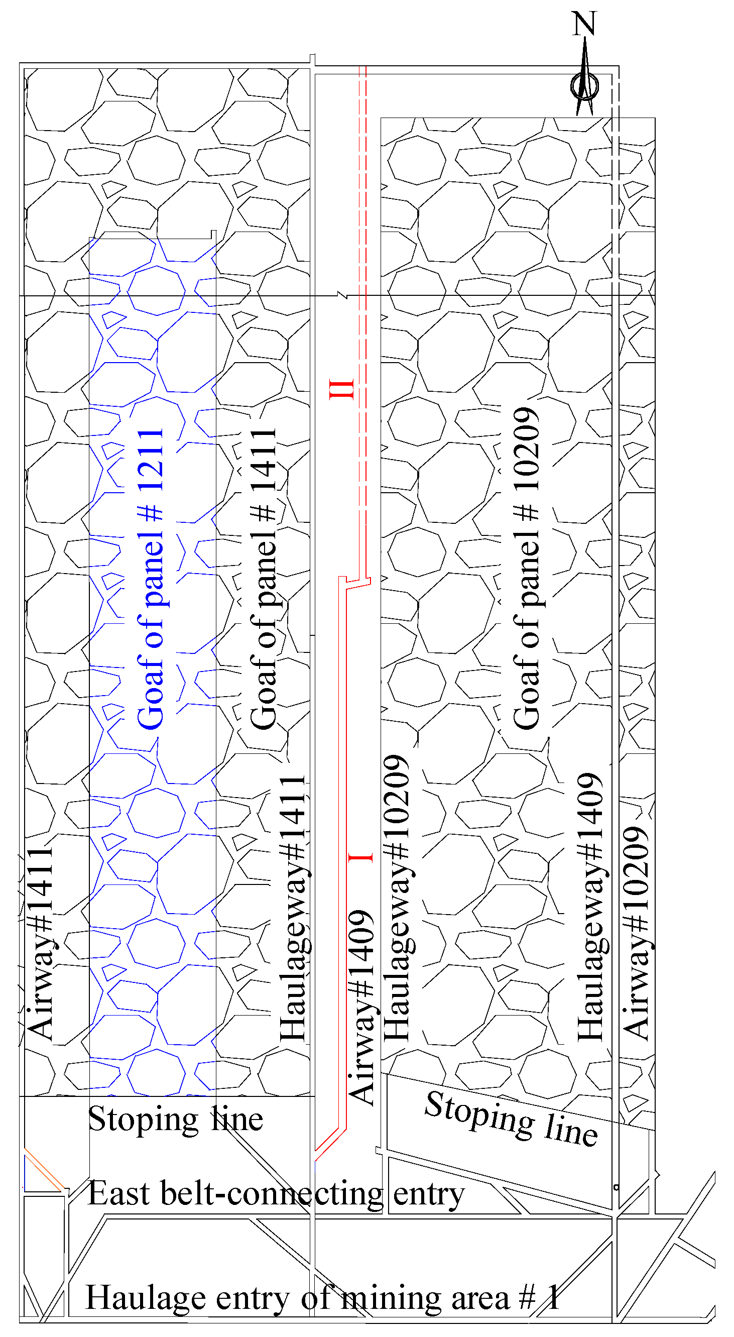
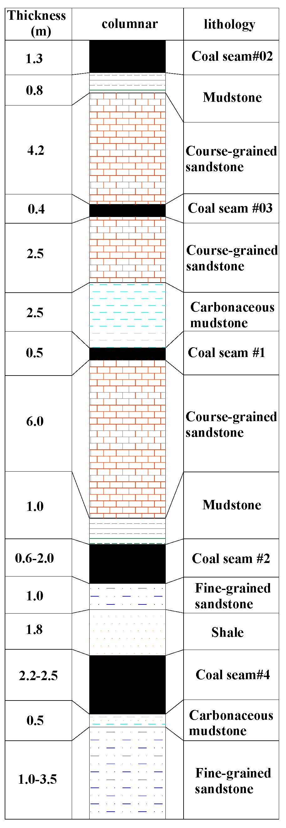
2. Overview of Test Roadway Project
3. Deformation and Failure Characteristics of Surrounding Rock of Roadway
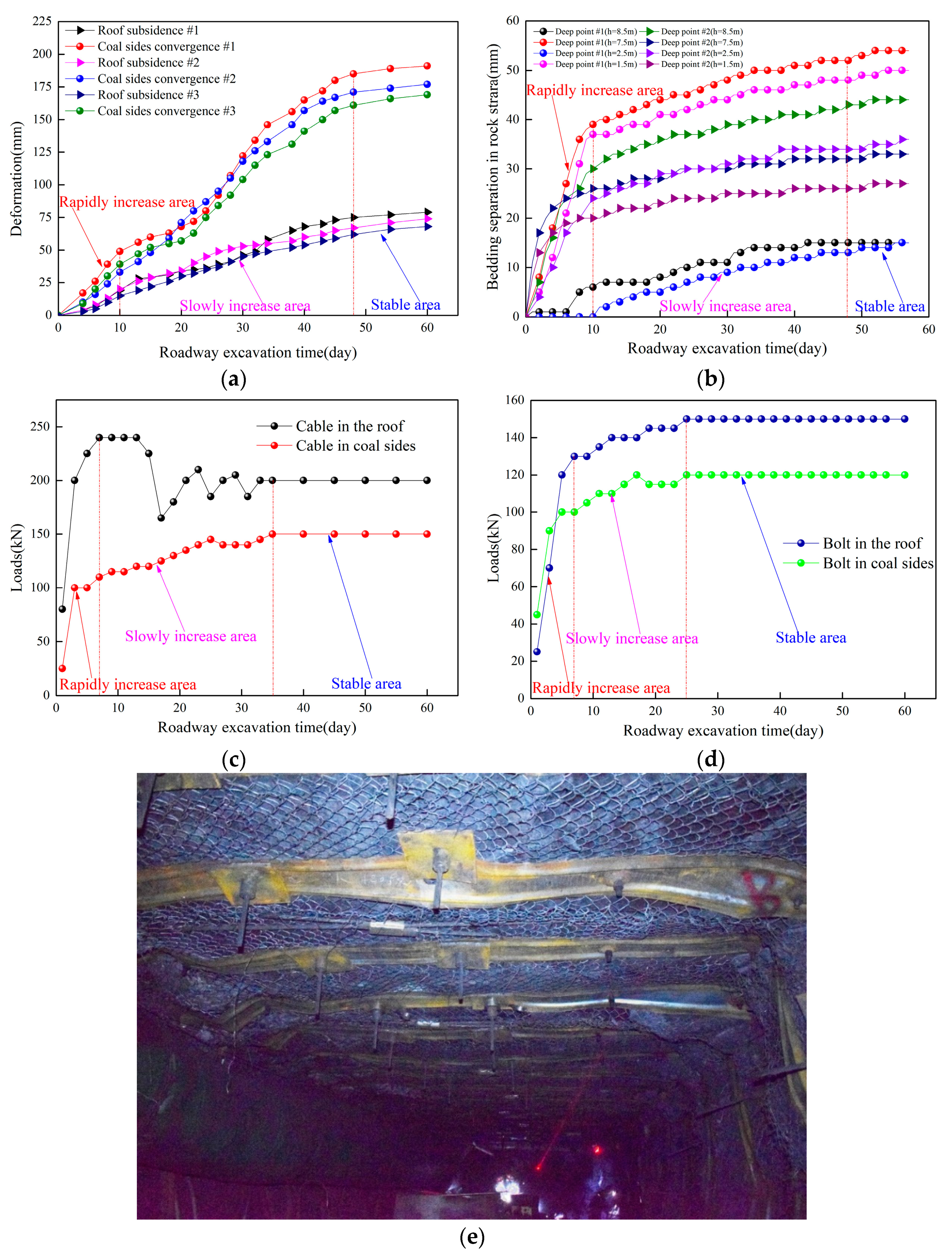
3.1. Deformation Law of Roadway Surrounding Rock
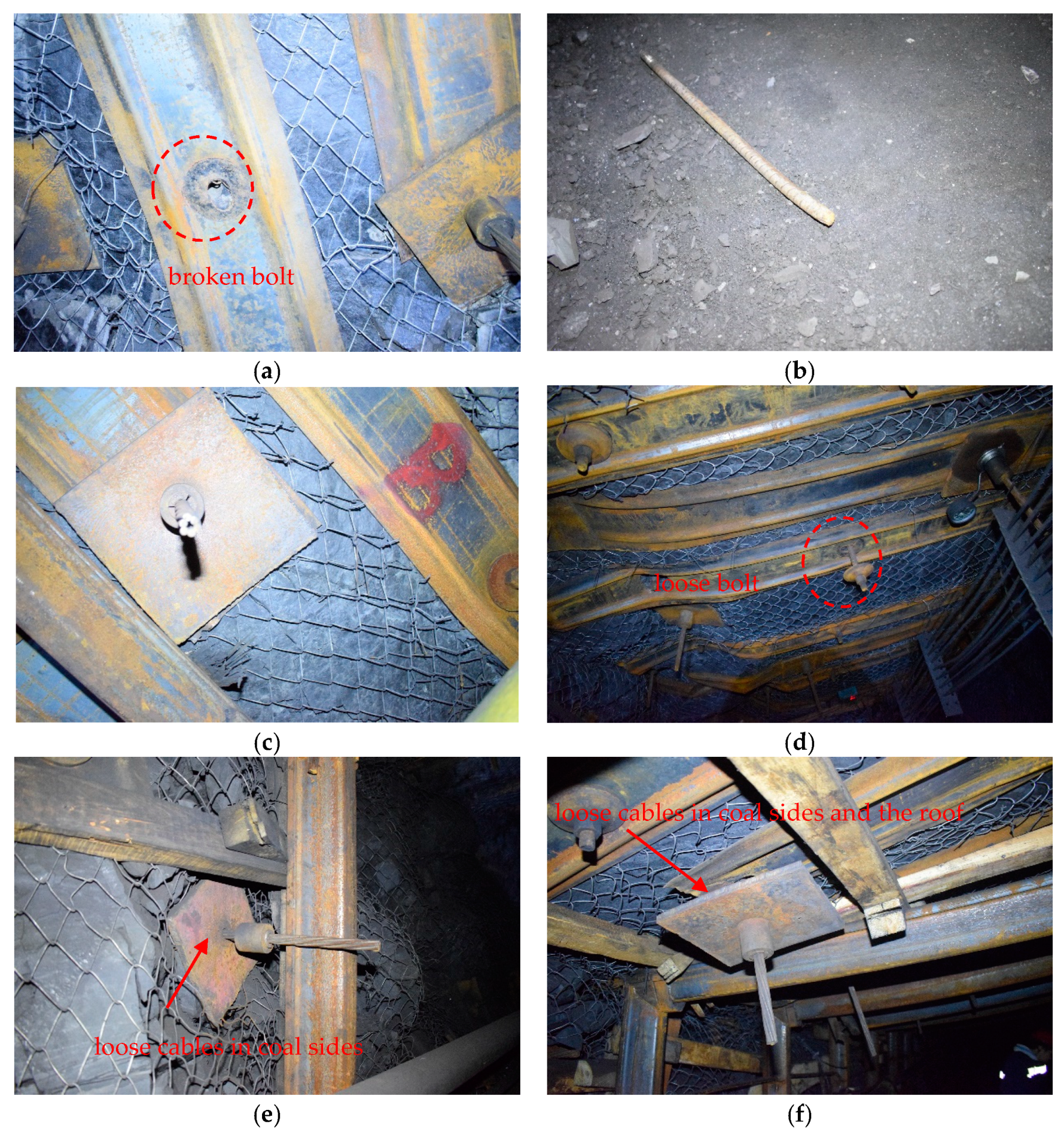
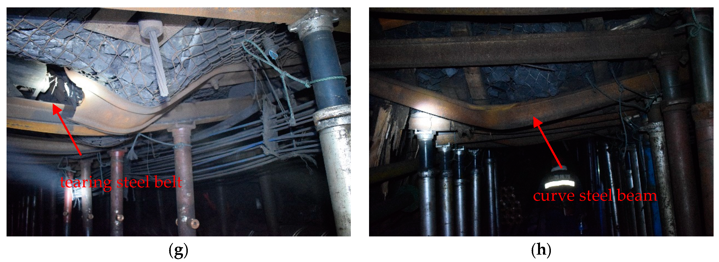
3.2. Analysis of Roadway Damaged Characteristics
- (1)
- The support from the upper wall has limited effectiveness. The bottom plate lacks support, and the support strength on the sides is significantly lower than the overall support strength on the roof. As a result, the roof, floor, and sides of the roadway gradually deform under the high mining stress.
- (2)
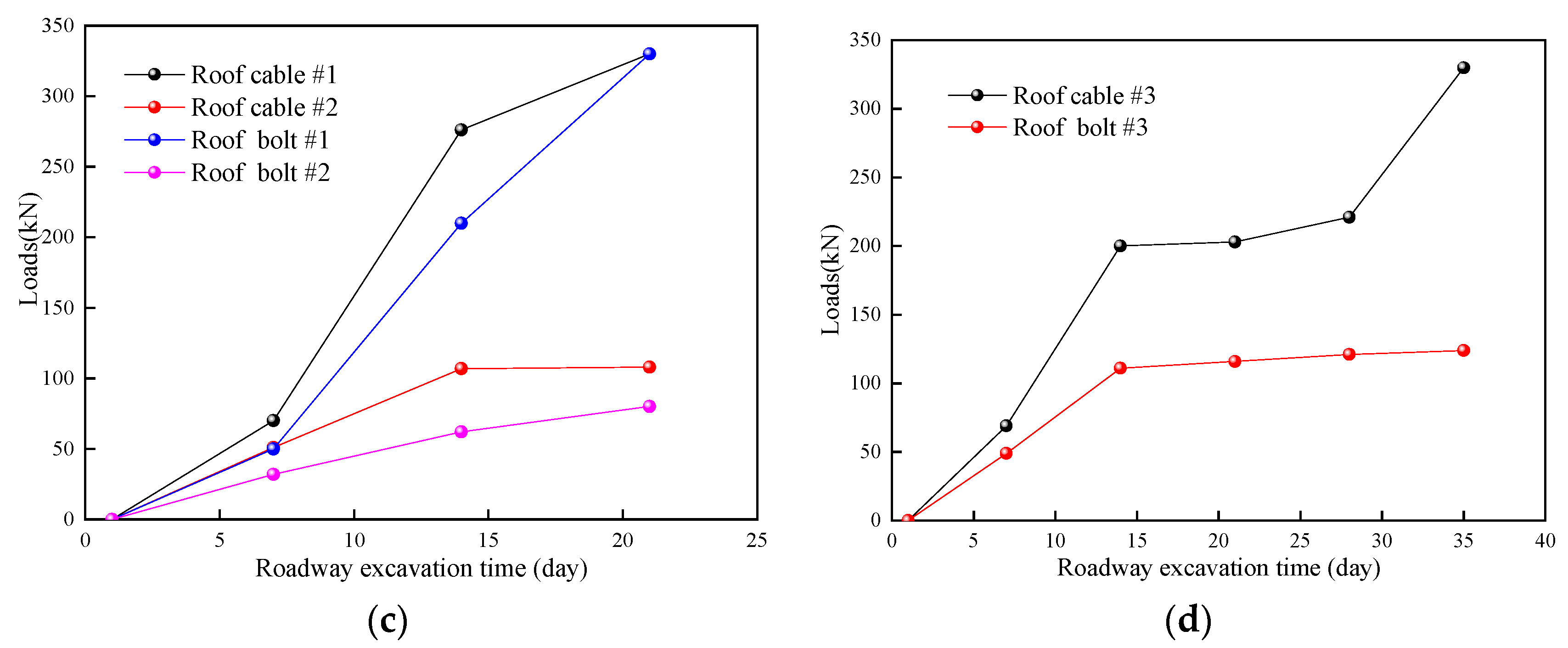
- There are significant differences between roof bolts and anchor cables. As the support strength increases during roadway excavation, the difference in support strength between anchor cables and anchor bolts becomes more pronounced. This leads to excessive stress on the anchor cables and very low stress on the anchor bolts during the initial stages of roadway construction. Additionally, the small anchoring area of a single anchor cable and the practice of combining roof anchor cables greatly reduce the effectiveness of the anchor cables.
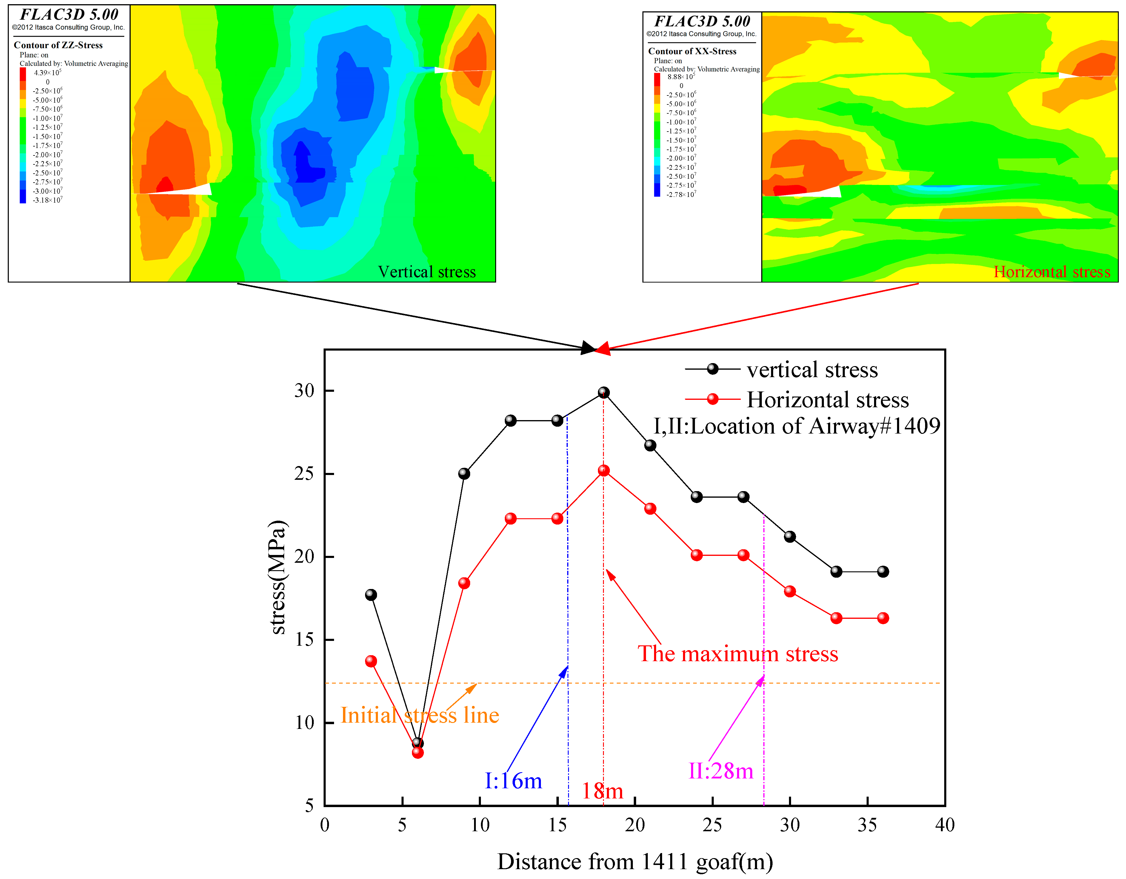
3.3. Analysis of Stress Concentration Area in Roadway
4. High Strength Prestressed Anchor Cable Truss Support System
4.1. Support Structure and Mechanism Analysis
- (1)
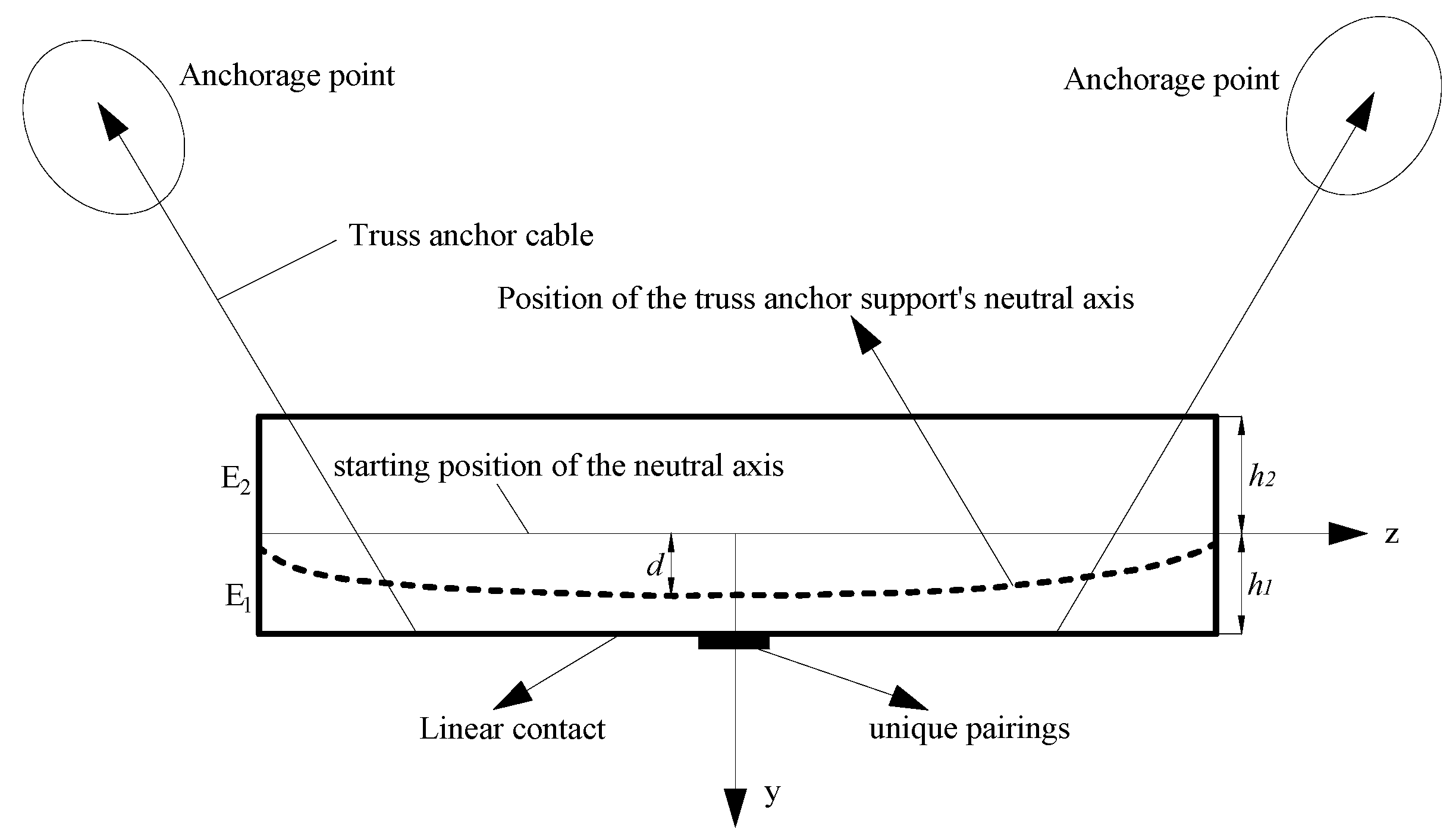
- Concept and design of truss anchor cables
- (2)
- Analysis of the truss anchor cable’s mechanics [33]
4.2. Truss Anchor Cable Numerical Simulation and Support Scheme
- (1)
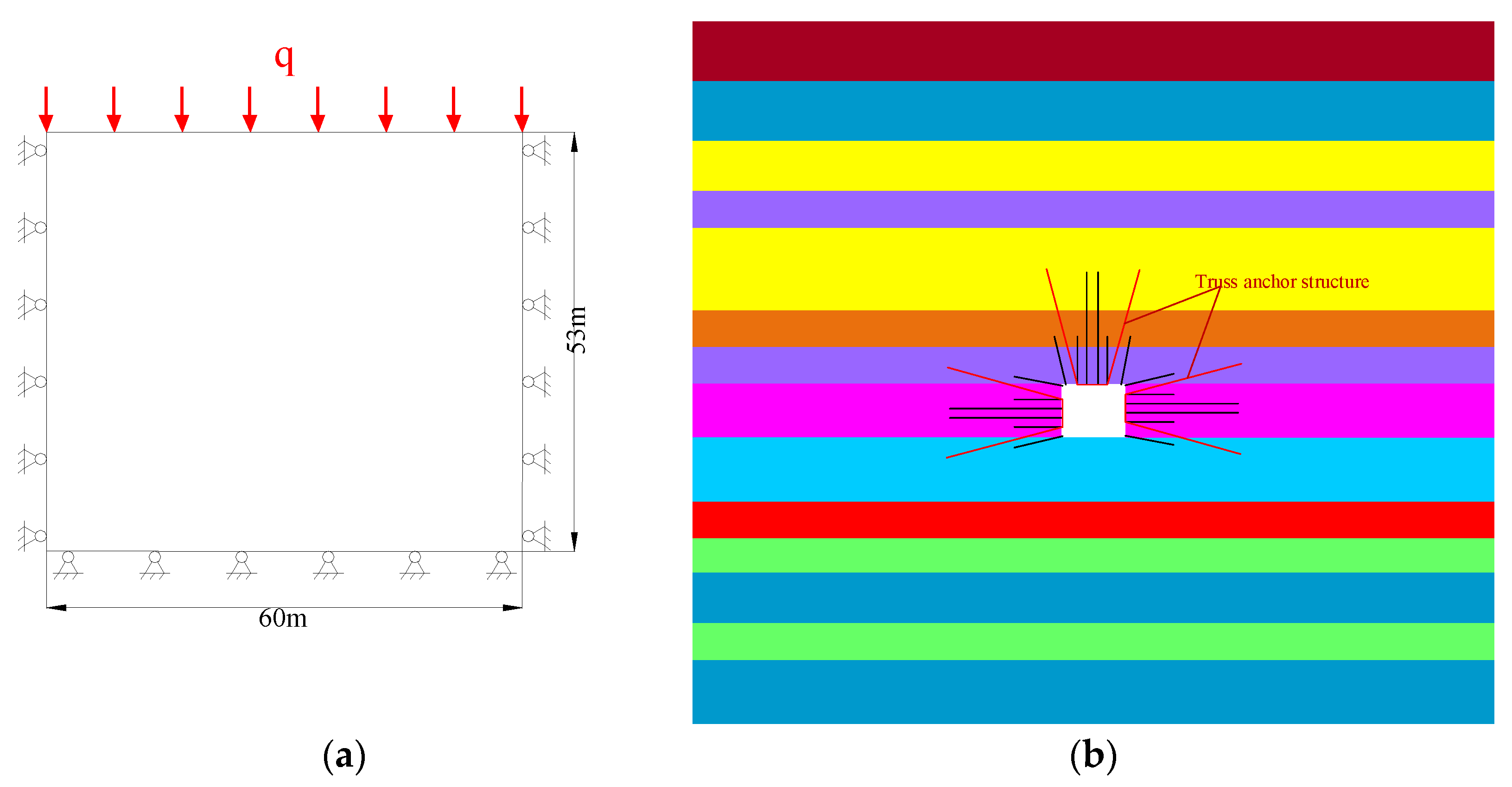
- Model building
- (2)
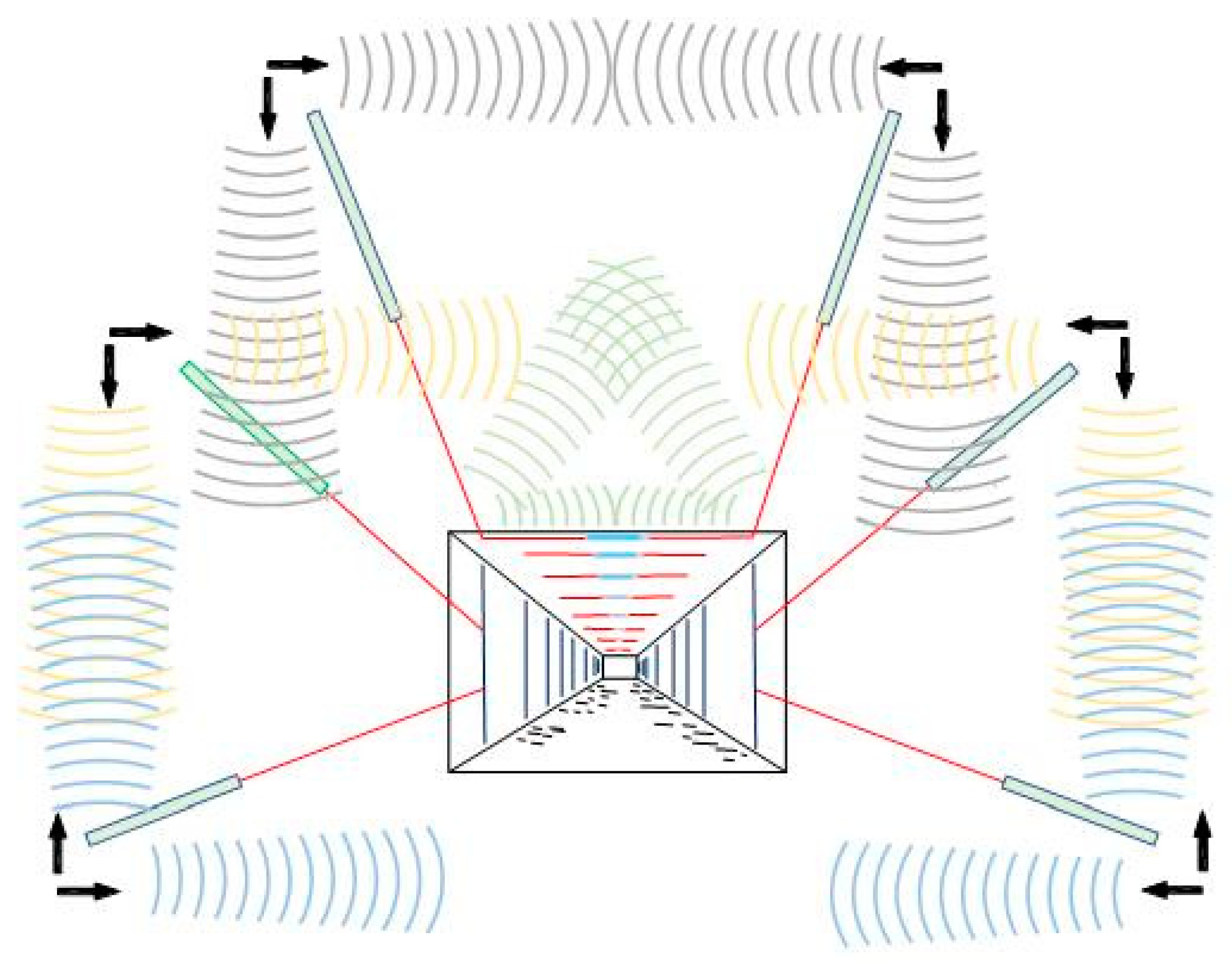
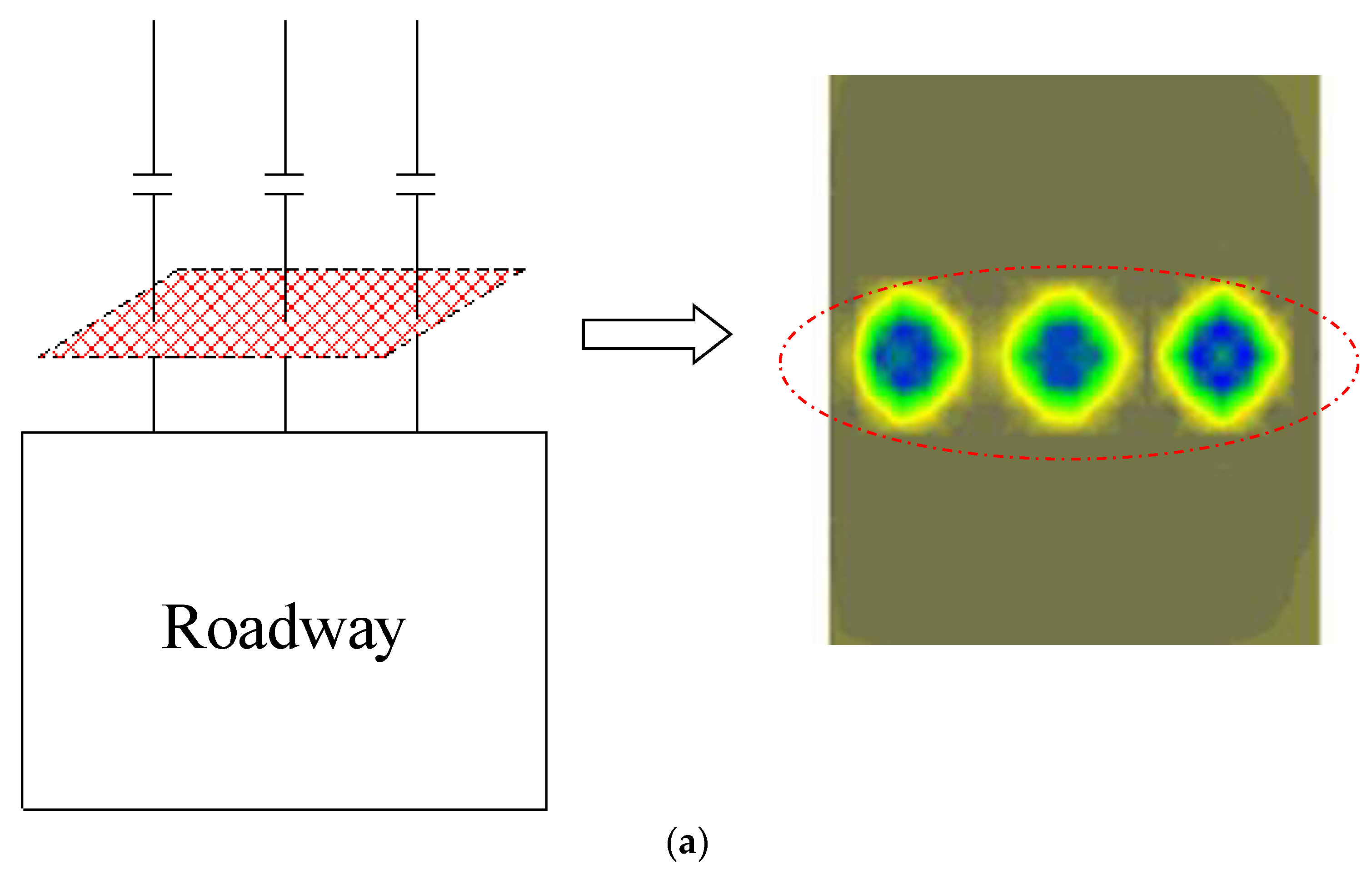
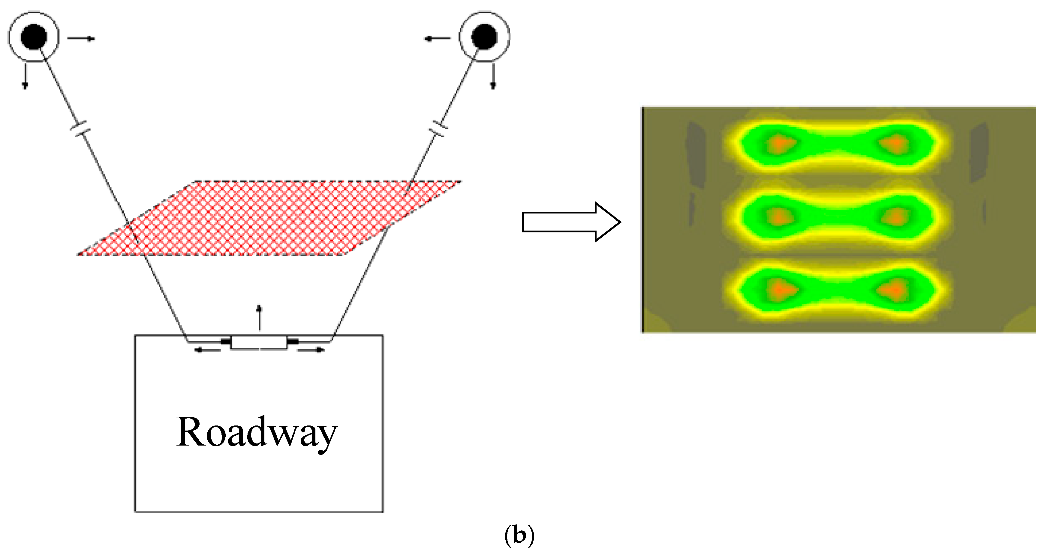
- Analysis of the anchor cable pre-stress field
- (3)
- Simulation of the support scheme analysis
5. Field Application and Monitoring
5.1. Support Scheme
- (1)
- Roof support
- (2)
- Roadway support
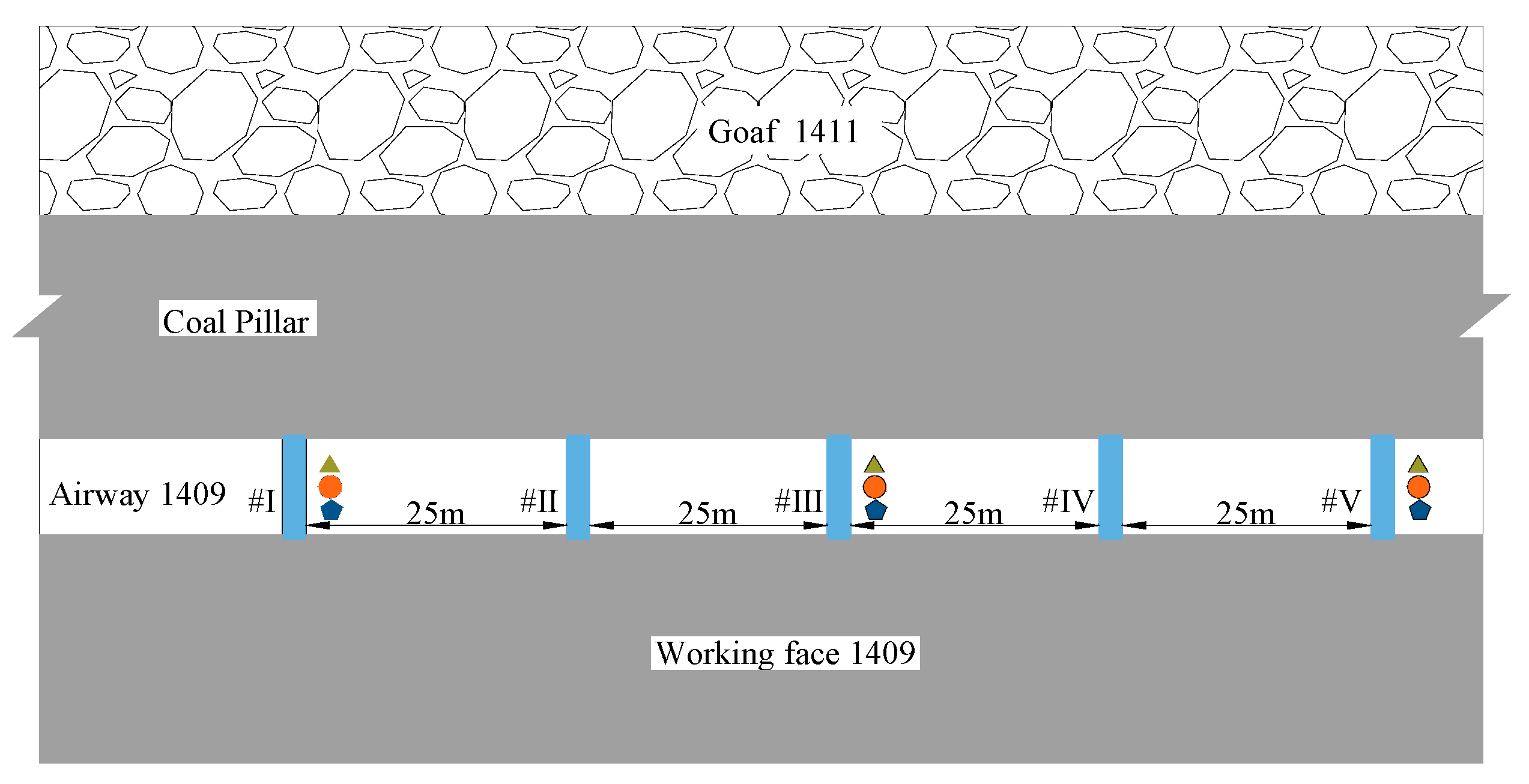
5.2. Field Monitoring Results
6. Discussion
7. Conclusions
- (1)
- The damaged types of the supporting structures and the deformation characteristics are concluded as follows: a. Six damaged supporting types are mainly obtained: broken bolt and cable, loose bolt and cable, tearing steel belt, and curved steel beam. b. Both the BSRS and the associated growth rate are generally large. c. Large deformations of surrounding roadways occur without the proper supporting scheme and have to face multiple repair activities during the roadway excavation period. d. The bolts and cables bearing loads have a large difference during the roadway excavation process, and the cables suffer from extreme high stresses, resulting in the combined bolt and cable supporting effect being weak and cables and bolts damaged in sequence.
- (2)
- Based on the difficult supporting roadway affected by the HSCA, the HSCTS support is put forward, and the main supporting effects and superiority are analyzed. Moreover, the supporting stress distribution characteristics were simulated, which showed the stress distribution field of the HSCTS is uniform and could benefit from forming a stable structure.
- (3)
- The supporting scheme with the core of the HSCTS and detailed parameters of the airway 1409 are determined and tested in the field; the findings indicate that the maximum value of shallow delamination is 44 mm, the maximum value of deep delamination is 54 mm, the top plate is not sinking more than 79 mm, and the two gangs are not moving in close proximity to one another more than 191 mm; and the monitoring results showed the surrounding rock deformation is much smaller than the former scheme with no repairing activities and testified to the significant supporting effect.
Author Contributions
Funding
Data Availability Statement
Conflicts of Interest
References
- Wu, Q.; Tu, K.; Zeng, Y.; Liu, S. Discussion on the main problems and countermeasures of building an upgraded version of China’s main energy (coal). J. Coal Ind. 2019, 44, 1625–1636. [Google Scholar]
- Yang, R.; Li, Y.; Guo, D.; Zhu, Y.; Yao, L.; Yang, T.; Yu, X. Reasons for deformation and failure of deep high stress soft rock roadway and support technology. J. Min. Saf. Eng. 2017, 34, 1035–1041. [Google Scholar]
- Li, C.; He, S.; Chen, L. Study on the mechanism and control measures of unsymmetrical roof fracture in large-span fault crossing soft rock roadway. J. Min. Saf. Eng. 2021, 38, 1081–1090. [Google Scholar]
- Xia, Y.; Pan, J.; Xie, F.; Feng, M.; Liu, S.; Lu, C. Disaster causing mechanism and control technology of repeated impact in the composite structural area of the main roadway in extra thick coal seam. J. Rock Mech. Eng. 2022, 41, 1–10. [Google Scholar]
- Zhang, J.; Yuan, R.; Li, Y. Study on surrounding rock control technology of thick mudstone composite roof coal roadway. J. Rock Mech. Eng. 2017, 36, 152–158. [Google Scholar]
- Kang, H.; Jiang, P.; Huang, B. Cooperative control technology of surrounding rock support—Modification—Pressure relief in 1000 meter deep mine roadway. J. Coal Ind. 2020, 45, 845–864. [Google Scholar]
- He, M.; Guo, Z. Mechanical properties and engineering application of constant resistance large deformation anchor. J. Rock Mech. Eng. 2014, 33, 1297–1308. [Google Scholar]
- Wang, Q.; Jiang, B.; Pan, R.; Li, S.C.; He, M.C.; Sun, H.B.; Qin, Q.; Yu, H.-C.; Luan, Y.-C. Failure mechanism of surrounding rock with high stress and confined concrete support system. Int. J. Rock Mech. Min. Sci. 2018, 102, 89–100. [Google Scholar] [CrossRef]
- Wang, Q.; Jiang, B.; Li, S.C.; Wang, D.C.; Wang, F.Q.; Li, W.T.; Ren, Y.X.; Guo, N.B.; Shao, X. Experimental studies on the mechanical properties and deformation & failure mechanism of U-type confined concrete arch centering. Roadwayl. Undergr. Space Technol. 2016, 51, 20–29. [Google Scholar]
- Liu, G.; Lin, Q.; Zhang, X. Stability analysis of surrounding rock supported by steel tube concrete support in high stress roadway. J. Shandong Univ. Technol. Nat. Sci. Ed. 2017, 31, 13–16. [Google Scholar]
- Xia, H.; Liu, G.; Liu, J.; Zhang, X.; Tian, T. Performance test of steel tube concrete support and its application in dynamic pressure roadway support. Coal Mine Saf. 2013, 44, 146–149. [Google Scholar]
- Yan, H.; He, F.; Xu, T. Research and practice on control system of double anchor cable truss in large section coal roadway of deep mine. J. Rock Mech. Eng. 2012, 31, 2248–2257. [Google Scholar]
- Wang, L.; Wang, Q.; Huang, Y.; Zhang, H.; Jiang, B.; Xu, Y.; Lu, W. Research on deformation mechanism and support technology of deep high stress cross seam roadway. J. Min. Saf. Eng. 2019, 36, 112–121. [Google Scholar]
- He, Z.; Chen, G. Research on Prestressed Cooperative Support Technology of Deep Roadway in Coal Mine. Coal Sci. Technol. 2013, 41, 35–38. [Google Scholar]
- Yuan, C. Study on Deformation and Failure Mechanism and Stability Control Principle of Surrounding Rock of Deep Roadway. Ph.D. Thesis, Hunan University of Science and Technology, Xiangtan, China, 2017. [Google Scholar]
- Yu, Y.; Bai, J.; Wang, X.; Wu, L.F.; Zhang, L.Y.; Xia, H.C. Research on layout and pressure relief control of roadway with residual coal pillar mining face. J. China Coal Soc. 2020, 45, 49–59. [Google Scholar]
- Wu, X.Y.; Liu, H.T.; Li, J.W.; Guo, X.F.; Lv, K.; Wang, J. Temporal-spatial evolutionary law of plastic zone and stability control in repetitive mining roadway. J. China Coal Soc. 2020, 45, 3389–3400. [Google Scholar]
- Gao, F.Q.; Stead, D.; Kang, H.P. Numerical simulation of squeezing failure in a coal mine roadway due to mining-induced stresses. Rock Mech. Rock Eng. 2015, 48, 1635–1645. [Google Scholar] [CrossRef]
- Suchowerska, A.M.; Merifield, R.S.; Carter, J.P. Vertical stress changes in multi-seam mining under supercritical longwall panels. Int. J. Rock Mech. Min. Sci. 2013, 61, 306–320. [Google Scholar] [CrossRef]
- Suchowerska, A.M.; Carter, J.P.; Merifield, R.S. Horizontal stress under supercritical longwall panels. Int. J. Rock Mech. Min. Sci. 2014, 70, 240–251. [Google Scholar] [CrossRef]
- Su, J.M.; Jiang, L.S.; Kong, P.; Wang, P.; Zhang, P.P. Numerical modeling approach on mining-induced strata structural behavior by considering the fracture-weakening effect on rock mass. Appl. Sci. 2019, 9, 1832. [Google Scholar]
- Li, Y.; Lei, M.X.; Wang, H.S.; Li, C.; Li, W.W.; Tao, Y.; Wang, J.Y. Abutment pressure distribution for longwall face mining through abandoned roadways. Int. J. Min. Sci. Technol. 2019, 29, 59–64. [Google Scholar] [CrossRef]
- Gao, R.; Yu, B.; Meng, X.B. Stress distribution and surrounding rock control of mining near to the overlying coal pillar in the working face. Int. J. Min. Sci. Technol. 2019, 29, 881–887. [Google Scholar] [CrossRef]
- Yang, W.; Lin, B.Q.; Yan, Q.; Zhai, C. Stress redistribution of longwall mining stope and gas control of multi-layer coal seams. Int. J. Rock Mech. Min. Sci. 2014, 72, 8–15. [Google Scholar] [CrossRef]
- Zhao, Y.; Luo, S.; Wang, Y.; Wang, W.; Zhang, L.; Wan, W. Numerical Analysis of Karst Water Inrush and a Criterion for Establishing the Width of Water-resistant Rock Pillars. Mine Water Environ. 2017, 36, 508–519. [Google Scholar] [CrossRef]
- Zhao, Y.; Liu, Q.; Zhang, C.; Liao, J.; Lin, H.; Wang, Y. Coupled seepage-damage effect in fractured rock masses: Model development and a case study. Int. J. Rock Mech. Min. Sci. 2021, 144, 104822. [Google Scholar] [CrossRef]
- Zhao, Y.; Zhang, C.; Wang, Y.; Lin, H. Shear-related roughness classification and strength model of natural rock joint based on fuzzy comprehensive evaluation. Int. J. Rock Mech. Min. Sci. 2020, 137, 104550. [Google Scholar] [CrossRef]
- Yu, W.; Li, K.; Liu, Z.; An, B.; Wang, P.; Wu, H. Mechanical characteristics and deformation control of surrounding rock in weakly cemented siltstone. Environ. Earth Sci. 2021, 80, 337. [Google Scholar] [CrossRef]
- Sakhno, I.; Sakhno, S. Numerical Studies of Floor Heave Control in Deep Mining Roadways with Soft Rocks by the Rock Bolts Reinforcement Technology. Adv. Civ. Eng. 2023, 2023, 2756105. [Google Scholar] [CrossRef]
- Guo, G.; Kang, H.; Qian, D.; Gao, F.; Wang, Y. Mechanism for Controlling Floor Heave of Mining Roadways Using Reinforcing Roof and Sidewalls in Underground Coal Mine. Sustainability 2018, 10, 1413. [Google Scholar] [CrossRef]
- Tahmasebinia, F.; Yang, A.; Feghali, P.; Skrzypkowski, K. Structural Evaluation of Cable Bolts under Static Loading. Appl. Sci. 2023, 13, 1326. [Google Scholar] [CrossRef]
- Tahmasebinia, F.; Yang, A.; Feghali, P.; Skrzypkowski, K. A Numerical Investigation to Calculate Ultimate Limit State Capacity of Cable Bolts Subjected to Impact Loading. Appl. Sci. 2023, 13, 15. [Google Scholar] [CrossRef]
- Yin, S.; Cai, W.; He, F.; Tian, D.; Shi, H. Mechanism and application of parallel-arranged composed of truss cable and single cable with high preload. J. China Univ. Min. Technol. 2014, 43, 823–830. [Google Scholar]
- Kang, X.; Zhao, H.; Xue, J. Theoretic analysis for hooping mechanism and composite elastic modulus of CFST members. Eng. Mech. 2007, 24, 121–125. [Google Scholar]


| No. | Floor Heave (mm) |
|---|---|
| a | 450 |
| b | 550 |
| c | 200 |
| d | 100 |
| e | 100 |
| Rock Type | Density | Bulk | Shear | Cohesion |
|---|---|---|---|---|
| (Kg·m−3) | (GPa) | (GPa) | (MPa) | |
| Siltstone | 2740 | 2.68 | 1.84 | 2.0 |
| Medium coarse grained sandstone | 2660 | 4.25 | 2.98 | 2.0 |
| Mudstone | 2600 | 3.03 | 1.56 | 1.2 |
| Coal | 1360 | 1.19 | 0.37 | 0.8 |
| Carbonaceous Mudstone | 2600 | 3.03 | 1.56 | 1.2 |
| Sandy mudstone | 2600 | 3.03 | 1.56 | 1.2 |
| Fine grained Sandstone | 2670 | 5.56 | 4.17 | 2.5 |
Disclaimer/Publisher’s Note: The statements, opinions and data contained in all publications are solely those of the individual author(s) and contributor(s) and not of MDPI and/or the editor(s). MDPI and/or the editor(s) disclaim responsibility for any injury to people or property resulting from any ideas, methods, instructions or products referred to in the content. |
© 2023 by the authors. Licensee MDPI, Basel, Switzerland. This article is an open access article distributed under the terms and conditions of the Creative Commons Attribution (CC BY) license (https://creativecommons.org/licenses/by/4.0/).
Share and Cite
Xu, Z.; Li, C.; Cao, Y.; Tai, L.; Yan, H. Study on the High Strength Cable Truss System Control of the Surrounding Coal Roadway Excavated in Regions Left Intensively Mining-Induced Stresses. Appl. Sci. 2023, 13, 10504. https://doi.org/10.3390/app131810504
Xu Z, Li C, Cao Y, Tai L, Yan H. Study on the High Strength Cable Truss System Control of the Surrounding Coal Roadway Excavated in Regions Left Intensively Mining-Induced Stresses. Applied Sciences. 2023; 13(18):10504. https://doi.org/10.3390/app131810504
Chicago/Turabian StyleXu, Zhijun, Chong Li, Yue Cao, Lianhai Tai, and Hong Yan. 2023. "Study on the High Strength Cable Truss System Control of the Surrounding Coal Roadway Excavated in Regions Left Intensively Mining-Induced Stresses" Applied Sciences 13, no. 18: 10504. https://doi.org/10.3390/app131810504
APA StyleXu, Z., Li, C., Cao, Y., Tai, L., & Yan, H. (2023). Study on the High Strength Cable Truss System Control of the Surrounding Coal Roadway Excavated in Regions Left Intensively Mining-Induced Stresses. Applied Sciences, 13(18), 10504. https://doi.org/10.3390/app131810504