Abstract
Composites based on Al-Fe alloys and reinforced with three-layer graphene sheets were synthesized “in situ” under a layer of molten salts. Composites containing 0.12 wt.% graphene were subjected to severe plastic deformation via high-pressure torsion. SEM and TEM were used to study the morphological and size characteristics of the composite structure in the as-cast and deformed states. Herein, it is shown that severe plastic deformation leads to the deformation-induced dissolution of iron-containing aluminides with the formation of a supersaturated Al solid solution with a submicrocrystalline structure. The hardness and electrical properties of the graphene composites were measured in different structural states and compared to the characteristics of the matrix alloy.
1. Introduction
In aluminum, iron has traditionally been considered an impurity that inevitably contaminates aluminum during recycling and reduces its mechanical properties. However, there has recently been growing research interest in binary aluminum–iron alloys containing up to 2% iron (here and elsewhere, the content of elements is given in wt.%) [1,2,3,4]. It has been shown that the addition of a small amount of iron to aluminum substantially improves the strength and plasticity of Al-Fe alloys, simultaneously preserving a rather high degree of electrical conductivity. This makes it possible to use Al-Fe alloys instead of binary [5,6] and rare earth metal (REM) reinforced Al-Zr alloys [7,8,9], as well as other Al alloys to which REMs are added [10,11,12].
Alloys with the minimum content of additives (alloying elements) in the Al matrix are known to exhibit the highest electrical conductivity. From this point of view, Al-Fe alloys are a good base for new and promising conductive alloys due to the low solubility of iron in an Al solid solution. Various techniques are used for strengthening such materials: rapid solidification [13], thermal treatment [14], mechanical alloying [15,16], and severe plastic deformation (SPD) [17,18,19,20]. Such a vast choice of treatments allows one to vary the composition, morphology, and size of iron-containing intermetallic phases, which determine the mechanical and electrical properties of the alloy as a whole. For example, authors have shown that during the SPD of rapidly crystallized Al-Fe alloys, the matrix structure is refined to 200 n, the Al6Fe aluminides are refined to 20 nm, and hardness reaches 1.5–2.0 GPa [13]. Using Mossbauer spectroscopy, the deformation-induced dissolution of Al6Fe and Al3Fe aluminides and the formation of an Al(Fe) solid solution and metastable Al9Fe2 aluminides were established during mechanical activation via shear under pressure induced by Bridgman anvils. The induction of dissolution with subtraction stoichiometry is explained by the facilitated release of aluminum (compared to iron) into the aluminum matrix and the accompanying process of the precipitation of metastable aluminides due to the saturation of the structure with deformation vacancies [19].
The development of efficient methods for the production of metal matrix composites (MMCs) has become a crucial task in material sciences. Composites based on aluminum alloys hold a prominent place among MMCs since they find application in various branches of industry [21,22]. For example, boride-reinforced composites based on Al-Mg-Si alloys are used as high-conductivity materials [23,24]. The addition of 3% aluminum boride AlB2 has been shown to strengthen the alloy and rid the Al solid solution of impurities, thereby improving its electrical properties.
In addition, there is intensive research on the properties of aluminum matrix composites with carbon-containing additives such as nanotubes and fullerenes [25,26]. A number of papers point out the positive role of graphene as a nanocarbon material with unique properties [26,27,28]. However, the wide application of aluminum matrix composites as construction materials is only possible if there are efficient techniques for their production.
As shown in [29,30,31,32], one such technique is “in situ” synthesis in a molten metal matrix under a layer of molten salts. This method has been used to obtain metal matrix composites based on aluminum [29,30] and its alloys of different compositions (AA-3003 [31], AA-5154 [32]) and doped with 0.10–0.13 wt.% graphene. Aluminum matrix composites have been studied in as-cast coarse-grained and in deformed-via-severe-plastic-deformation ultrafine-grained (grain size < 1 μm) states. The study of their structures and properties revealed an effect of microalloying with graphene. Graphene is not an inoculant and does not affect the grain size of as-cast aluminum matrix composites. The hardness of these as-cast composites depends on the chemical composition of the matrix and is 5–10% greater than that of unreinforced Al alloys.
When an ultrafine-grain structure is formed in composites via high-strain-rate deformation, graphene nanoplatelets break up, bend, and primarily occupy the position along the grain–subgrain boundaries, providing an additional strengthening mechanism due to an interaction with the dislocations. The transition from a coarse-grained structure to an ultrafine-grained structure brings about a sharp increase in the hardness of the composites, namely, by a factor of 1.6 in the composites based on an Al-Mn alloy and by a factor of 2.6 in a AlGr composites [30].
Follow-up research on “in situ” synthesized graphene aluminum matrix composites was carried out using an Al-Fe alloy as a matrix. The aim of this paper is to study the structure formation and electrical and thermal properties of AlFeGn composites in the as-cast state and after deformation via high-pressure torsion.
2. Materials and Methods
Composites based on Al-2.5%Fe alloy reinforced with 0.12% graphene were investigated. The synthesis of such aluminum–matrix composites was described in detail in [29,30,31,32] and involved the reaction of a molten Al-2.5% Fe alloy used as the matrix with a carbon-containing precursor under a layer of molten halide salts (sodium and potassium chlorides with the addition of ammonium fluorides). Molten salts were used as salt flux. Boron carbide was used as the carbon-containing precursor in the synthesis of composites based on Al-Fe alloy. The amount of boron carbide was 2 mass %. The synthesis temperature was 750 °C, and the time the liquid Al-Fe alloy was held in the molten salt was 1–5 h. The synthesis of the carbon atoms was a one-step process taking place directly in the molten alloy. Initially, in the process of self-assembly, carbon clusters were formed, followed by the appearance of continuous films that were evenly distributed in the volume of the solidifying melt.
Cylindrical samples 10 mm in diameter and 70 mm in height were cast into a metal mold. The structures and properties of the composites were compared with the corresponding characteristics of the Al-2.5%Fe matrix alloy cast under the same thermophysical conditions. The content of carbon and iron in the composites was evaluated via spectral analysis using ICPE-9000 SHIMADZU spectrometer with inductively coupled plasma (the error was ±0.005 wt.%) (Table 1).

Table 1.
Chemical composition of the samples (wt.%).
Carbon in the Al-Fe matrix was examined using Raman spectroscopy via a Renishaw U-1000 instrument. The spectral lines were approximated using the built-in Wire-30 software package and Fityk 0.9.8 data analysis application.
Thermal conductivity was measured on a NETZSCH LFA 467 Hyper Flash device using the laser flash method according to ASTM E-1461, DIM EN 821, and DIN 30,905 international standards.
Severe plastic deformation (SPD) of the composite and the matrix alloy was induced for samples with a 1 mm thickness and a 10 mm diameter via high-pressure torsion (HPT) at a pressure of 4 GPa at room temperature. There were n = 5 and 10 anvil revolutions, and the true strain values at the mid-radius of the samples were e = 3.54 and 4.13, respectively.
The macrostructure of the samples was studied by means of a NEOPHOT-32 optical microscope and a scanning electron microscope (SEM) (TESCAN MIRA 2, equipped with an Oxford Instruments UltimXmax energy-dispersive X-ray spectral microanalysis (MRSA) system with AZtec 5.1 software). The samples for structural analysis were prepared with the application of mechanical polishing in a Cr2O3 suspension. Final polishing was performed on a suspension of colloidal silicon dioxide.
Fine-structure examination was performed using TECNAI G 30 Twin transmission electron microscope (TEM) with an accelerating voltage of 300 kV. The samples for fine-structure examination were made via jet polishing in a Tenupol-5 device in a solution of 20% nitric acid and 80% methanol at a temperature of −25 °C and a voltage of 15–20 V.
X-ray diffraction analysis was performed using a Bruker Advance-D8 diffractometer with CuKα-radiation (Kα = 0.15418 nm) at scattering angles of 18–145° with a step of 0.02° and 2 s exposure time. The diffraction patterns were analyzed using DIFFRAC.EVA 4.0, DIFFRAC.TOPAS 5.0 software, and PDF 2.1202 database.
Billets in the form of thin rods with dimensions of 10 × 1 × 1 mm for the cast samples and 10 × 1 × 0.3 mm for the deformed samples were cut via the electric spark method for use in the specific electrical resistance measurements. Temperature dependences of electrical resistance were determined using the standard four-probe method under DC with the commutation of current flow through the sample at temperatures from 78 K to 330 K.
The hardness data were obtained using the Vickers test on a Qness Q10A+ automatic hardness tester under a load of 0.05 N and with a holding time of 10 s. Three series of tests were performed for each sample, with each series including 20 measurements along the whole diameter of the specimen. Since the structures of the HPT-subjected specimens were non-homogeneous along the radius, mean values at the mid-radius were considered for comparison with the hardness values.
3. Results and Discussion
3.1. Structure and Hardness
The structural modification of the carbon phase in the volume of Al-Fe matrix was studied using Raman spectroscopy. The Raman spectrum of the carbon inclusions shown in Figure 1 contains a characteristic G peak at 1576 cm−1, a D peak at 1347 cm−1, and a 2D peak at 2699 cm−1, meaning that the carbon inclusions can be identified as graphene [33]. The analysis of carbon peaks’ intensity ratios allows for the determination of the structural properties of graphene [34]. The intensity ratio of the 2D to G bands, I2D/IG, was found to be 0.48, which implies the formation of triple-layer graphene. This type of graphene has very few defects since the intensity ratio of D peaks, characterizing the deficiency of the carbon film, to G peaks, ID/IG, was found to be 0.29, which is far below unity. The presence of a small kink (D′ at 1600 cm−1) indicates the appearance of five–seven-membered rings in the graphene structure.
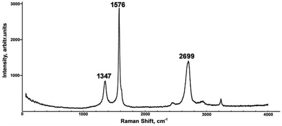
Figure 1.
Raman spectrum of the AlFeGn composite.
A comparison of the results of the metallographic studies of the macrostructures of the cross-sections of the AlFe alloy and AlFeGn composite ingots is shown in Figure 2.
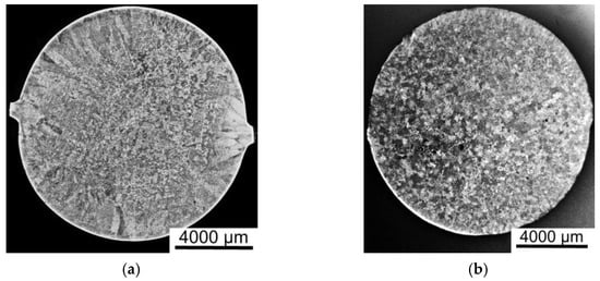
Figure 2.
The macrostructures of the cross-sections of the ingots: the AlFe alloy (a) and the AlFeGn composite (b).
Figure 2 shows that the microalloying of aluminum with graphene changes the nature of crystallization. The ingot of the AlFe alloy has a zonal structure, consisting of columnar and equiaxed grains (Figure 2a), and in the ingot of the composite, a zone of columnar grains is absent (Figure 2b). The grain size is practically the same (400–600 µm), i.e., graphene is not an inoculant and does not modify the as-cast structure of the aluminum alloy, and this finding agrees with the results previously obtained for other aluminum matrix composites incorporating graphene [29,30,31,32]. The uniformity of the composite structure may be due to its higher thermal conductivity resulting from the addition of graphene, which can clearly be seen in Figure 3. All the values of the thermal conductivity of the matrix alloy lie below the ones for the thermal conductivity of the composites. The higher the thermal conductivity of the metal, the faster the melt temperature equalizes over the volume of the bath. As the temperature difference of the melt near the walls of the crucible and in its center becomes smaller, the melt cooling rate decreases, and supercooling at the crystallization front increases. Such thermo–physical conditions of crystallization contribute to the suppression of the growth of the columnar structure [35].
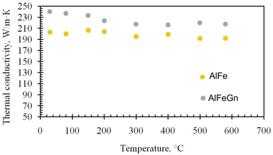
Figure 3.
Thermal conductivity of the AlFe alloy and AlFeGn composite.
Based on these data, it can be supposed that during the crystallization of the composite, the temperature gradient in the volume of the melt quickly equalizes; consequently, the nucleation and growth of the solid phase proceed at the same temperature and rate along the cross-section of the ingot, resulting in the formation of a uniform macrostructure.
A comparison of the hardness values of the matrix alloy and the composite shows that the hardness of the as-cast composites differs from the hardness of the matrix alloy by no more than 10–15% and equals 39–42 HV. A similar effect was previously observed in experiments investigating the effect of graphene on the structure of aluminum matrix composites incorporating magnesium and manganese [30,31].
According to the relevant phase diagram, Al-2.5%Fe has a hypereutectic composition (1.8%Fe is the eutectic point) [36]. Since the cooling conditions are not homogeneous when the melt is cast in the mold, the alloy compositions close to the eutectic point have a non-homogeneous, non-uniform structure with several constituents: an Al solid solution, primary iron aluminides, and eutectics.
Figure 4 shows the structure of the composite consisting of Al solid solution dendrites 15–20 μm in size, with clearly defined degenerate eutectics ((Al) + Al13Fe4) along their boundaries (Figure 4a) and needle-shaped primary crystals of Al13Fe4 10–40 μm long and 1–3 μm wide (Figure 4b). Figure 4c,d show the microstructure of the AlFe alloy. The comparison of the composite microstructure with that of the matrix alloy shows that the addition of graphene did not result in the change in the volume fraction, the density of distribution, size, or morphology of the main structural constituents.
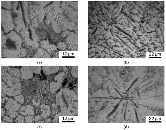
Figure 4.
Microstructure of the as-cast AlFeGn composite (a,b) and as-cast AlFe alloy (c,d).
The evolution of the structure under HPT was studied using two structural analysis techniques: scanning and transmission electron microscopy. The backscattered electron images indicate that deformation resulted in the structural refinement of the main constituents in the materials investigated and changed their forms and sizes.
The pertinent backscattered electron image of the structure shows the evolution of the shape and size of Fe aluminides in the process of deformation with the increase in n (Figure 5). HPT induced the breakage and fragmentation of the primary needle-like Al13Fe4 precipitates, with the formation of more equiaxed crystals closer to eutectic crystals in size. As a result of mass transfer upon applying HPT (n = 10), the particles of iron aluminides are evenly distributed in the volume of the sample, and the average size of all Fe-containing phases decreased to 0.58 μm (Figure 5b,c).
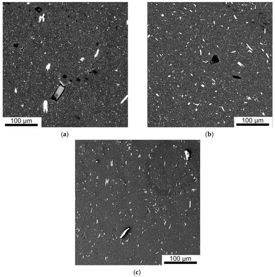
Figure 5.
Backscattered electron images of the microstructure of the as-cast (a) and HPT-deformed n = 5 (b) and n = 10 (c) AlFeGn composites.
XRD analysis showed that the addition of graphene did not affect the phase composition of the matrix, and the diffraction patterns of the AlFe alloy and AlFeGn composite in the as-cast and deformed states were identical. Figure 6 shows a comparison of sections of diffraction patterns for the as-cast and deformed composites. The range of 2θ was chosen to show the most intense reflections from the detected phases, i.e., the Al solid solution and the Al6Fe and the Al13Fe4 aluminides. The Al6Fe phase presumably belongs to eutectic aluminides. The indexing of diffraction reflections in the range of angles 2θ = 18–145° did not reveal any additional structural components of the composite. Reflections from the Al6Fe and the Al13Fe4 phases are clearly visible in the diffraction pattern of the as-cast composite. The intensity and number of reflections from these phases decreased in the diffraction pattern of the deformed composite since the aluminides were crushed and partially dissolved during HPT.
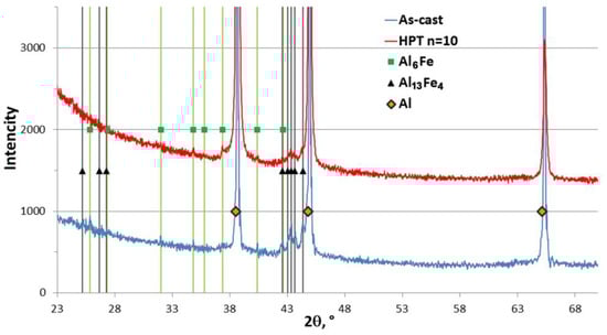
Figure 6.
Diffraction patterns of AlFeGn in the as-cast and deformed (HPT n = 10) states.
The transmission electron microscopy (TEM) images clearly show structural changes in the matrix when the composite was subjected to HPT. The results for the AlFeGn composite after HPT (n = 10) are given below. According to Figure 7a,b, HPT induced a rather uniform ultrafine-grained (UFG) structure consisting of grains from 90 to 450 μm in size. The grain–subgrain size distributions indicate that the minimum-sized grains of 90 nm make up 7%. (Figure 8). The percentage of large crystals 390–450 nm in size does not exceed 10%, and most of the grains have a size of 150 to 250 nm.
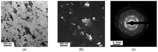
Figure 7.
The microstructure of AlFeGn composite: bright-field image (a); dark-field image in (111)Al and (200)Al reflections (b); SAED pattern (c).
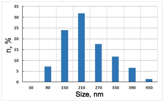
Figure 8.
Grain–subgrain size distribution of AlFeGn composite after HPT, n = 10.
The shape of most of the grains is close to equiaxial. The grains are primarily separated by quite perfect rectilinear high-angle boundaries, and this was confirmed by the ring-like nature of the selected-area electron diffraction pattern with a lot of discrete point reflections (Figure 7c) and dark-field images obtained in the matrix reflections (Figure 7b).
The bright-field images show non-uniform deformation-induced contrast inside certain grains, which indicates a high degree of internal stress (Figure 7a). On the other hand, the absence of an internal substructure and the accumulation of dislocations inside the grains, as well as the rather fine, perfect high-angle boundaries, indicate a rather equilibrium-consistent UFG structure that apparently formed via low-temperature dynamic recrystallization. The absence of precipitates inside the grains and the absence of reflections other than those of Al on the selective area electron diffraction pattern show that the decomposition of the supersaturated Al solid solution and the precipitation of hardening phases did not occur under HPT at n = 10.
The lattice period of the Al matrix in the deformed composite and the matrix alloy was determined in order to assess the possibility of oversaturated solid solution formation under HPT.
It is known that the accuracy of determining the lattice period depends on the measurement error of the interplanar distance and the accuracy of finding the diffraction angle (θ). Taking this into account, the precision determination of the lattice period of the Al matrix in the deformed AlFeGn composite and deformed AlFe alloy was carried out by measuring the interplanar distances of the HKL {331} and {420} planes at diffraction angles 2θ equal to 112 and 115°, respectively. The lattice periods averaged over two values are shown in Table 2. According to [36], iron being in solid solution reduces the aluminum lattice period: 1 wt.%Fe reduces it by 0.005 Å. By knowing the change in the Al lattice period under deformation (Δa = a(n=0) − a(n=10)), one can calculate the amount of iron that passes into solid solution under HPT. The grating periods averaged over two values of the Al solid solution are shown in Table 2.
Table 2.
Lattice periods of the Al matrix before and after HPT.
The calculations show that the content of iron in the Al solid solution of the AlFe alloy was 0.48%, while in the composite, it rose to 0.74%. Thus, SPD not only leads to grain refinement but also results in the deformation-induced dissolution of disperse iron aluminides and the formation of supersaturated Al solid solutions. Such structural features contribute to the strength of the materials, which was pointed out more than once in experimental studies using SPD methods [16,17,18]. This strengthening is achieved via the sum of contributions from various structural mechanisms, i.e., the grain–boundary (the Hall–Petch relationship), dispersion (the Orowan mechanism), dislocation (proportional to the dislocation density), and solid solution (proportional to the content of the alloying element in the Al solid solution).
Figure 9 shows the behavior of the hardness of the samples of different compositions under HPT with different numbers of revolutions (n).
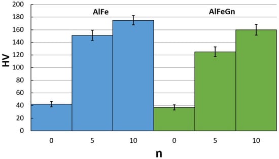
Figure 9.
Hardness of the AlFe alloy and the AlFeGn composite before and after HPT.
The data obtained indicate that the hardness increased sharply after HPT by n = 5; with a higher degree of deformation, the hardness growth declines. After deformation at n = 10 (e = 4.13), the maximum hardness of the samples reaches 160–170 HV, which exceeds the hardness of the as-cast counterparts by a factor of 4.
Based on the above-presented results of the structural studies and hardness measurements, one can conclude that the grain boundary, solid solution, and dispersion mechanisms make the greatest contributions to the hardening and strengthening of the deformed AlFe alloy and AlFeGn composite. The addition of 0.12% graphene did not affect the hardness values. This result needs an explanation. Previous research and comparison of the hardness values for single-phase as-cast and UFG AlGn and AlMgGn composites showed that structural refinement resulted in the increase in these material hardness [36]. The hardness of the AlGn composite increased by 25%, and the hardness of the matrix of the AlMgGn composite increased by no more than 15–20%. Concerning the hardness of AlFeGn composites, it is necessary to take into account both the grain size and the number of intermetallic particles. In particular, after HPT, a heterogeneous multiphase UFG structure is formed in the AlFe alloy, in which dispersed Fe aluminides increase the material hardness due to their small size. The structure of the UFG composite after HPT is more homogeneous, with fewer aluminides and a more iron-supersaturated Al solid solution. Given the equal contribution of grain boundary strengthening (the equal grain–subgrain size of the HPT AlFe and AlFeGn samples) to the total hardness of the AlFe alloy and AlFeGn composite, a decrease in the dispersion strenthening and an increase in the solid solution strengthening in the AlFeGn composite can equalize the absolute values of hardness.
Thus, HPT produced an aluminum–graphene composite with a very high hardness, the structure of which consists of a large number of disperse iron aluminides alongside an SMC iron-supersaturated Al solid solution.
3.2. Electrical Properties
Figure 10 contains the temperature dependences of specific electrical resistance ρ for the samples of different compositions after HPT with various numbers of revolutions.
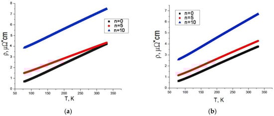
Figure 10.
Specific electrical resistance of the matrix alloy (a) and the composite (b) after HPT with various numbers of revolutions vs. temperature.
The plots of ρ(T) show the same trend of specific electrical resistance of the matrix alloy and the composite: deformation-induced growth of the electrical resistance and reduced dependence of resistance on temperature (a lower angle of the slope). Values of electrical resistance at room temperature, 293 K, were chosen for a comparative analysis of electrical resistance of the matrix alloy and the composite and its evolution with the number of revolutions during HPT (Table 3). The data indicate that deformation with n = 10 induced the highest increase in electrical resistance in all the samples. The values of specific electrical resistance were used to calculate the specific electrical conductivity σ of the composites in absolute units σ = 1/ρ and in the relative units of the IACS international standard:
where σCu = 58 MS/m (Table 3).
IACS = σAlFeGn/σCu (× 100%),
Table 3.
Electrical properties of the matrix alloy and the composite at room temperature.
Based on the analysis of the structure of the deformed samples, it can be concluded that the growth in their specific electrical resistance and the decrease in their conductivity may be related to the formation of defects and to the deformation-induced dissolution of iron aluminides, which result in the formation of a supersaturated Al solid solution. Obviously, the increase in the iron content in the Alsolid solution, which accompanies the intensification of intermetallic phase dissolution, will increase resistance and decrease conductivity. According to the calculations of the lattice perioda, the supersaturation of the Al solid solution reaches its maximum in the AlFeGn composite after n = 10 (Table 2). Assuming that, with all else being equal (with respect to the degree of defective of all the samples after n = 10), the different values of conductivity are only due to the Fe content in the solid solution, the composite should have a lower conductivity compared to the matrix alloy. The values for the conductivity given in Table 3 indicate the opposite: the conductivity of the composite is higher than the conductivity of the matrix alloy both in the as-cast and in the deformed state. Thus, it can be concluded that the addition of graphene to the as-cast alloy as well as the HPT alloy not only fully compensated for the drop in specific electrical conductivity but also increased its value compared to that of the matrix alloy. The difference in electrical conductivity is 6% in the as-cast state and 3% IACS after HPT.
4. Conclusions
- Comparison of the macrostructure of the matrix alloy with the structure of the composite, in which there was no zone of columnar crystals, suggests that the reason for the different solid phase growth pattern is the higher thermal conductivity of the composite due to the addition of graphene.
- Metallographic techniques were employed to establish that graphene used as reinforcement did not have modifying properties and did not affect the size and morphology of the structural constituents in the as-cast composites. Nonequilibrium crystallization of the AlFe alloy and the AlFeGn composites led to the formation of dendrites of Al solid solution 15–20 µm in size with degenerate eutectic along the grain boundaries and primary needle-like Al13Fe4 crystals of 10–40 µm long and 1–3 µm wide.
- HPT produces an UFG structure with an average grain size of 200 nm and induces the breakage and fragmentation of the eutectic and primary crystals of iron aluminides and their partial deformation-induced dissolution with the formation of a supersaturated solid solution of Fe in Al.
- The hardness of the deformed composite is four times higher than the hardness of the composite in the as-cast state, and its electrical resistance is two times less. This strengthening was achieved via the sum of contributions from various structural mechanisms, i.e., grain– boundary (the Hall–Petch relationship), dispersion (the Orowan mechanism), dislocation (proportional to density of dislocftion), and solid-solution mechanisms (proportional to the content of the alloying element in the Al solid solution).
- The micro-addition of graphene increases the specific electrical conductivity of the composite both in the as-cast and in the deformed states compared to the matrix alloy.
Author Contributions
Conceptualization, I.G.B. and L.A.Y.; Methodology, I.G.B., A.N.P., D.Y.R. and L.A.Y.; Investigation, R.V.M., D.Y.R., A.N.P., V.V.M., B.M.F. and A.A.M.; results analysis, I.G.B., A.N.P., D.Y.R., V.V.M. and L.A.Y.; Writing—Review and editing, I.G.B. and A.N.P. All authors have read and agreed to the published version of the manuscript.
Funding
This research was carried out within the state assignments of the Ministry of Science and Higher Education of the Russian Federation (Theme “Struktura” No 122021000033-2 (IMP UB RAS) and the Research Program N 122020100210-9 (IHTE UB RAS)).
Institutional Review Board Statement
Not applicable.
Informed Consent Statement
Not applicable.
Data Availability Statement
Data can be transmitted on demand.
Acknowledgments
The electron microscopic studies were performed at the Center of Collaborative Access Test Center of Nanotechnologies and Advanced Materials, Institute of Metal Physics of the Ural Branch of the Russian Academy of Sciences (Ekaterinburg, Russia). The Raman spectra for graphene and thermal conductivity were collected using the equipment of the Shared Access Center Composition of Compounds of Institute of High-Temperature Electrochemistry of the Ural Branch of the Russian Academy of Sciences (Ekaterinburg, Russia).
Conflicts of Interest
The authors declare no conflict of interest.
References
- Shikagawa, T.; Itoh, G.; Suzuki, S.; Kuroda, H.; Horikoshi, T. Effect of small additions of Fe on the tensile properties and electrical conductivity of aluminium wires. Mater. Sci. Forum 2016, 519, 515–518. [Google Scholar]
- Medvedev, A.E.; Murashkin, M.Y.; Enikeev, N.A.; Ovid’ko, I.A.; Valiev, R.Z. Optimization of strength-electrical conductivity properties in Al-2Fe alloy by severe plastic deformation and heat treatment. Adv. Eng. Mater. 2018, 20, 1700867. (In Russian) [Google Scholar] [CrossRef]
- Cubero-Sesin, J.M.; Horita, Z. Age Hardening in Ultrafine-Grained Al-2PctFe Alloy Processed by High-Pressure Torsion. Metall. Mater. Trans. A Phys. Metall. Mater. Sci. 2015, 46, 2614–2624. [Google Scholar] [CrossRef]
- Murashkin, M.Y.; Enikeev, N.A.; Ovid’ko, I.A.; Valiev, R.Z. Strength and electrical conductivity of ultra—Fine grained aluminum alloy Al-2Fe subjected to annealing and straining. Mater. Phys. Mech. 2015, 24, 297–307. (In Russian) [Google Scholar]
- Belov, N.A.; Alabin, A.N.; Matveeva, I.A.; Eskin, D.G. Effect of Zr additions and annealing temperature on electrical conductivity and hardness of hot rolled Al sheets. Trans. Nonferrous Met. Soc. China Engl. Ed. 2015, 25, 2817–2826. [Google Scholar] [CrossRef]
- Zhang, Y.-Z.; Gao, H.-Y.; Wang, Y.-F.; Wang, J.; Sun, B.-D.; Gu, S.-W. Effects of addition on microstructure and properties of Al-Zr alloys. Trans. Nonferrous Met. Soc. China Engl. Ed. 2014, 24, 2239–2243. [Google Scholar] [CrossRef]
- Zhang, Y.; Zhou, W.; Gao, H.; Han, Y.; Wang, K.; Wang, J. Precipitation evolution of Al-Zr-Yb alloys during isochronal aging. Scr. Mater. 2013, 69, 477–480. [Google Scholar] [CrossRef]
- Wen, S.P.; Gao, K.Y.; Li, Y.; Huang, H.; Nie, Z.R. Synergetic effect of Er and Zr on the precipitation hardening of Al-Er-Zr alloy. Scr. Mater. 2011, 65, 592–595. [Google Scholar] [CrossRef]
- Medvedev, A.E.; Hodgson, P.D.; Lapovok, R.; Murashkin, M.Y.; Enikeev, N.A.; Valiev, R.Z. Enhancement of mechanical and electrical properties of Al-Re alloys by optimizing rare-earth concentration and thermos-mechanical treatment. J. Alloys Compd. 2018, 745, 696–704. [Google Scholar] [CrossRef]
- Eliezer, D.; John, G.; Froes, F.H. Mossbauer study of rapidly solidified Al-rare-earth alloys. J. Mater. Sci. Lett. 1986, 5, 781–782. [Google Scholar] [CrossRef]
- Yu, X.W.; Cao, C.A.; Yan, C.W.; Yao, Z.M. Rare earth application in sealing anodized Al-based metal matrix composites. J. Mater. Sci. Technol. 2001, 17, 283–284. [Google Scholar]
- Murashkin, M.Y.; Medvedev, A.E.; Enikeev, N.A.; Valiev, R.Z.; Sabirov, I.; Lefebvre, W.; Sauvage, X. Mechanical and electrical properties of an ultrafine grained Al-8.5% RE (RE=5.4Ce, 3.1wt.% La) alloy processed by severe plastic deformation. Mater. Des. 2016, 90, 433–442. [Google Scholar] [CrossRef]
- Kim, D.H.; Cantor, B. Structure and decomposition behaviour of rapidly solidified Al-Fe alloys. J. Mater. Sci. 1994, 29, 2884–2892. [Google Scholar] [CrossRef]
- Cubero-Sesin, J.M.; Watanabe, M.; Arita, M.; Horita, Z.J. Aging and precipitation behavior in supersaturated Al-2%Fe alloy produced by high-pressure torsion. In Proceedings of the 14th International Conference on Aluminium Alloys, Trondheim, Norway, 15–19 June 2014; Trans Tech Publications Ltd.: Zurich, Switzerland, 2014; pp. 766–771. [Google Scholar]
- Llurma, J.A.; Benito, A.; Rosa, A.; Cabrera, J.M.; Prado, J.M. Study of the nanometric grain size distribution in iron compacts jbtained by mechanical milling. Mater. Sci. Forum 2006, 503–504, 1007–1012. [Google Scholar] [CrossRef]
- Sasaki, T.T.; Ohkubo, T.; Hono, K. Microstructure and mechanical properties of bulk nanocrystalline AlFe alloy processed by mechanical alloying and spark plasma sintering. Acta Mater. 2009, 57, 3529–3538. [Google Scholar] [CrossRef]
- Senkov, O.N.; Froes, F.H.; Stolyarov, V.V.; Valiev, R.Z.; Liu, J. Microstructure of aluminum-iron alloys subjected to severe plastic deformation. Scr. Mater. 1998, 38, 1511–1516. [Google Scholar] [CrossRef]
- Medvedev, A.E.; Zhukova, O.O.; Kazykhanov, V.U.; Shaikhulova, A.F.; Enikeev, N.A.; Timofeev, V.N.; Murashkin, M.Y. On the effect of ECAP and subsequent cold rolling on the microstructure and properties of electromagnetically cast Al-Fe alloys. Int. J. Lightweight Mater. Manuf. 2022, 5, 484–495. [Google Scholar] [CrossRef]
- Uesugi, T.; Takigawa, Y.; Higashi, K. Deformation mechanism of nanocrustalline Al-Fe alloys by analysis from Al-Initio calculation. Mater. Sci. Forum 2006, 503–504, 209–214. [Google Scholar] [CrossRef]
- Tcherdyntsev, V.V.; Kaloshkin, S.D.; Afonina, E.A.; Tomilin, I.A.; Baldokhin, Y.V.; Shelekhov, E.V. Effect of deformation by high pressure torsion on the phase composition and microhardness of mechanically alloyed and rapidly quenched Al-Fe. Defect Diffus. Forum 2003, 216–217, 313–322. [Google Scholar] [CrossRef]
- Das, D.K.; Mishra, P.C.; Singh, S.; Thakur, R.K. Properties of ceramic-reinforced aluminium matrix composites—A review. Int. J. Mech. Mater. Eng. 2014, 9, 12. [Google Scholar] [CrossRef]
- Khrustalev, A.P.; Kozulin, A.A.; Zhukov, I.A.; Khmeleva, M.G.; Vorozhtsov, A.B.; Eskin, D.G.; Chankitmunkong, S.; Platov, V.V.; Vasilev, S.V. Influence of Titanium Diboride Particle Size on Structure and Mechanical Properties of an Al-Mg Alloy. Metals 2019, 9, 1030. [Google Scholar] [CrossRef]
- Karabay, S. Influence of AlB2 compound on elimination of incoherent precipitation in artificial aging of wires drawn from redraw rod extruded from billets cast of alloy AA-6101 by vertical direct chill casting. Mater. Des. 2008, 29, 1364–1375. [Google Scholar] [CrossRef]
- Cui, X.; Wu, Y.; Liu, X.; Zhao, Q.; Zhang, G. Effects of grain refinement and boron treatment on electrical conductivity and mechanical properties of AA1070 aluminum. Mater. Des. 2015, 86, 397–403. [Google Scholar] [CrossRef]
- Bakshi, S.R.; Lahiri, D.; Agarwal, A. Carbon nanotube reinforced metal matrix composites—A review. Int. Mater. Rev. 2010, 55, 41–64. [Google Scholar] [CrossRef]
- Sheinerman, A.G. Mechanical properties of metal matrix composites with graphen and carbon nanotubes. Phys. Met. Metallogr. 2022, 123, 57–84. [Google Scholar] [CrossRef]
- Hu, Z.; Tong, G.; Lin, D.; Chen, C.; Guo, H.; Xu, J.; Zhou, L. Graphene-reinforced metal matrix nanocomposites—A review. Mater. Sci. Technol. 2016, 32, 930–953. [Google Scholar] [CrossRef]
- Pérez-Bustamante, R.; Bolaños-Morales, D.; Bonilla-Martínez, J.; Estrada-Guel, I.; Martínez-Sánchez, R. Microstructural and hardness behavior of graphene-nanoplatelets/aluminum composites synthesized by mechanical alloying. J. Alloys Compd. 2014, 615 (Suppl. 1), S578–S582. [Google Scholar] [CrossRef]
- Shirinkina, I.G.; Brodova, I.G.; Rasposienko, D.Y.; Muradymov, R.V.; Yolshina, L.A.; Shorokhov, E.V.; Razorenov, S.V.; Gorkushin, G.V. Influence graphene additions on aluminum structure and properties. Phys. Met. Metallogr. 2020, 121, 1193–1202. [Google Scholar] [CrossRef]
- Brodova, I.; Yolshina, L.; Razorenov, S.; Rasposienko, D.; Petrova, A.; Shirinkina, I.; Shorokhov, E.; Muradymov, R.; Garkushin, G.; Savinykh, A. Effect of Grain Size on the Properties of Aluminum Matrix Composites with Graphene. Metals 2022, 12, 1054. [Google Scholar] [CrossRef]
- Brodova, I.G.; Petrova, A.N.; Shirinkina, I.G.; Rasposienko, D.Y.; Yolshina, L.A.; Muradymov, R.V.; Razorenov, S.V.; Shorokhov, E.V. Mechanical properties of submicrocrystalline aluminium matrix composites reinforced by “in situ” graphene through severe plastic deformation processes. J. Alloys Compd. 2021, 859, 158387–158395. [Google Scholar] [CrossRef]
- Brodova, I.G.; Yolshina, L.A.; Rasposienko, D.Y.; Muradymov, R.V.; Shirinkina, I.G.; Razorenov, S.V.; Petrova, A.N.; Shorokhov, E.V. Structure formation and physical-mechanical properties of Al-Mg alloy with microadditions of graphene. Lett. Mater. 2022, 12, 269–275. [Google Scholar] [CrossRef]
- Vanin, M.; Mortensen, J.J.; Kelkkanen, A.K.; Garcia-Lastra, J.M.; Thygesen, K.S.; Jacobsen, K.W. Graphene on metals: A van der Waals density functions study. Phys. Rev. B 2010, 87, 081408. [Google Scholar] [CrossRef]
- Sharma, R.; Chadha, N.; Saini, P. Determination of defect density, crystallite size and number of graphene layers in graphene analogues using X-ray diffraction and Raman spectroscopy. Indian J. Pure Appl. Phys. 2017, 55, 625–629. [Google Scholar]
- Winegard, W.C. An Introduction to the Solidification of Metals; Department of Metallurgy University of Toronto: Toronto, ON, Canada; The Institute of Metals: London, UK, 1964. [Google Scholar]
- Mondolfo, L.F. Aluminum Alloys: Structure and Properties; Butterworth & Co: London, UK, 1976. [Google Scholar]
Disclaimer/Publisher’s Note: The statements, opinions and data contained in all publications are solely those of the individual author(s) and contributor(s) and not of MDPI and/or the editor(s). MDPI and/or the editor(s) disclaim responsibility for any injury to people or property resulting from any ideas, methods, instructions or products referred to in the content. |
© 2023 by the authors. Licensee MDPI, Basel, Switzerland. This article is an open access article distributed under the terms and conditions of the Creative Commons Attribution (CC BY) license (https://creativecommons.org/licenses/by/4.0/).