Featured Application
The present study can be used for the development of high-lift flow-control devices for future civil aircraft.
Abstract
To provide sufficient lift during takeoff and landing, large aircraft are equipped with complicated high-lift devices. The use of simple flaps coupled with active flow control (AFC) can achieve lift improvement while reducing mechanical structure and weight. The present study focuses on verifying the feasibility and effectiveness of simple flaps combined with sweeping jet flow control. An experimental study on the AFC of flaps, using sweeping jets, was carried out using a NASA SC(2)-0410 supercritical airfoil wind-tunnel model at Re = 2.0 × 10⁵ (with velocity V = 10 m/s). In the experiment, the wing angle of attack (α) ranged from 3 to 18°, and the flap deflection angle (δ) ranged from 0 to 30°; the aerodynamic characteristics and surface pressure characteristics of the wing at typical working conditions were analyzed. Using sweeping jets to control the flow on the flaps, the momentum coefficients (for three actuator groups) of the jet are 0.8%, 3.6%, and 8.2%, respectively, and the maximum lift coefficient was increased by approximately 33%. The influence of the sweeping jet flow rate on the aerodynamic performance of the airfoil is analyzed. There are two main reasons for the lift coefficient increase caused by sweeping jet flow: an extra suction peak near the flap and a suction peak increase near the leading edge area caused by induced flow.
1. Introduction
The lift-up system is one of the key components of the wings of modern aircraft. One of the critical design indicators of the system is to allow an aircraft with transonic cruising speed to land safely at low speeds.
However, owing to the large number of components, heavy weight, complexity, intensive maintenance, and long design-test time, the lifting system has a significant effect on the cost and safety of the aircraft [1]. It is now common to use lift-boosting devices such as Fowler flaps, which are slits at the trailing edge of the wing. These devices are complex in structure and require additional fairing as they protrude from the wing, resulting in an overall increase in weight and additional cruise resistance [2,3].
A lift-boosting system with active flow control (AFC) combined with simple flaps was proposed as an alternative that could provide sufficient lift while reducing associated external drag. In the 1990s, McLean et al. [4] explored a range of AFC applications designed to improve the efficiency of the next generation of commercial transonic transport aircraft. However, manufacturers view simplified lift systems with enhanced AFC as a high-risk though high-yield technology that reduces aircraft target weight and fuel consumption. The rationale behind AFC is that it will reduce wing separation when typical lift-up systems are replaced with mechanically simpler and lighter variants. To this end, researchers have carried out a series of flap-lift experiments or vertical tail enhancement using AFC methods such as synthetic jets [5] and oscillatory jets [6,7,8,9]. Among them, owing to the particularity of its own structure, an oscillating jet can generate a sweeping jet at its exit [8], thus facilitating a larger control area on the wetted surface, making this kind of actuator application unique to AFC [10].
As one kind of effective AFC technology, the sweeping jet has been considered a more practical flow controller than other existing technologies [11], and it is widely applied in other different sceneries. For example, the dynamics of oscillating jet emitted in confined and non-confined backward-facing step geometries were investigated with TR-PIV to resolve the mechanism of flow separation and reattachment that occurs at a sharp corner, which will help the application of fluidic oscillators in heat transfer enhancement or cooling process [12]. In addition, an experimental study on the flow control capability of sweeping jet actuators in an aggressive offset S-shaped duct with a compressed incoming flow was conducted to suppress flow separation in the duct and flow distortion at the aerodynamic interface plane. With the sweeping jet actuators controls, the absolute pressure recovery increased by nearly 5%, and the mean value and RMSE of the cross-flow velocity declined by 54.9% and 48.1%, respectively [13].
In aerospace engineering applications, in 2016, Boeing successfully used a sweeping jet to enhance the control characteristics of the vertical tail on the 757 environmental protection verification machines [14]. Based on the success of this application, a lifting system using AFC combined with simple flaps was proposed. This alternative can provide sufficient lift while reducing the associated external drag, and the scheme can effectively reduce the weight of the lifting system [15]. The scheme uses single-hinged flaps, which produce a higher deflection angle (δ). Experimental studies show that if the lift-increasing system of AFC combined with simple flaps is used to obtain the same lift-increasing effect as Fowler flaps, the fuel consumption can be reduced by up to 2.25% [16]. Subsequently, the scheme of oscillating jets combined with simple flaps has been systematically studied as an alternative to the high-lift system.
In 2017, Shmilovich et al. [17] used numerical simulation to prove that AFC on flaps using sweeping jets could greatly reduce the required mass flow rate. In an experiment at the NASA Langley Research Center, the control effect of oscillating and steady jets for two flap deflection angles on the Fast-MAC model was tested [18]; the results proved that when the flap deflection angle was 30°, the oscillating jet saved approximately 54% of the mass flow rate compared with the steady jet. In 2018, Melton et al. [19] used force and moment data, particle-image velocimetry data, and both steady-state and unsteady surface pressure data on the NACA0015 two-dimensional straight-wing model to prove that oscillating jets can produce more benefits with less mass flow in active-flap flow control and lift.
To further promote AFC technology of the oscillating jet in engineering practice, researchers designed a high-lift general research model (CRM-HL) and used it in a series of numerical simulations and experimental studies [20,21,22]. Vatsa et al. [20,23] carried out CFD calculations using the model data used in the CRM-HL experiments. Other researchers used CFD that led to a series of related wind-tunnel experiments [21,24]. Finally, researchers at the NASA Langley Research Center conducted subsonic wind-tunnel tests using a 10% scale civilian aircraft wing model. A variety of AFC schemes were tested in the experiments, and a lift coefficient increment of 0.5 was ultimately achieved [25].
In the aforementioned results, researchers focused more on the measurement of lift coefficient for different flow-control systems, the modification of the fluidic oscillator [26,27], or the fundamental physics of the oscillating jet [28,29,30], but less on the specific effect of sweeping jet AFC on wing surface pressure [31] and the reason for the lift improvement after applying the sweeping jet. To address this, the work described in this paper uses the NASA SC(2)-0410 airfoil in the design of a two-dimensional straight-wing model. The influence of sweeping jet flow control on wing surface pressure distribution is analyzed via aerodynamic force measurement and wing surface pressure measurement. The outcome of the present study might help engineers understand how to better improve the lift during the takeoff stage and provide validation data for the flow control technology design and CFD simulation on AFC technology.
2. Experimental Set-Up
2.1. Testing Facilities
The experimental research was performed at the low-speed, low-turbulence wind tunnel (LLW) at Nanjing University of Aeronautics & Astronautics (NUAA), a schematic of which is shown in Figure 1. The LLW is a research-grade, open jet recirculation wind tunnel with a test volume of 1.5 m (width) × 1 m (height) × 1.7 m (length). The wind speed of the test section ranges from 0.5 to 30 m/s, with a turbulence level of less than 0.1%.
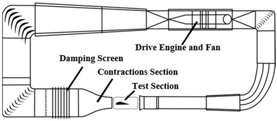
Figure 1.
Low-speed, low-turbulence wind tunnel (LLW).
2.2. Models
The selected airfoil in this experiment was the NASA SC(2)-0410, a supercritical airfoil in the form of a two-dimensional straight-wing model made using three-dimensional printing from resinous material; a planform view of the wing is shown in Figure 2. The wing chord length (c) and span (l) were 300 mm and 400 mm, respectively, and the flap position was set in the range 70–100% of the chord length. The hinges of the flap were embedded in the model and were controlled using a square-section carbon fiber rod as a rotating shaft. The deflection angle of the flap varied from 0° to 30° and was controlled using a fixed-angle deflection plate. In addition, 26 pressure tappings were arranged on the symmetrical plane of the wing: 12 each on the upper and lower surface of the wing, 1 on the leading edge, and 1 on the trailing edge.
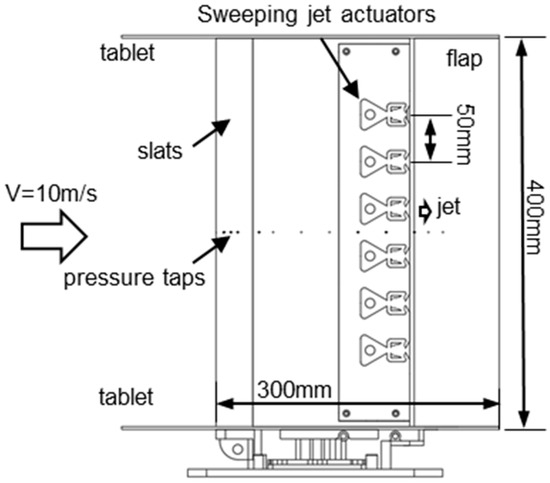
Figure 2.
Wing model and layout of the sweeping jet actuators.
Six sweeping jet actuators were designed according to the literature and uniformly embedded on the wing model with equal spanwise spacing (d = 50 mm) [23]. The outlets of the actuators were located at 70% of the chord (from the leading edge and tangent to the airfoil surface).
The actuators were grouped in pairs, with each group sharing a common air pipeline for gas transmission, thus reducing the unevenness of the gas supply. The key internal dimensions of the sweeping jet actuators are shown in Figure 3. As shown in the figure, the length of each actuator is 24 mm, and the width and thickness are 24 mm and 2 mm, respectively. The width at the throat of the actuator is 4 mm, as is the width of the feedback channel. The 10 mm diameter compressed-air inlet was located at the left-hand side of the actuator, and the width of the inlet of the working section of the actuator is 6 mm. For the sweeping jet outlet, the diffusion angle of the actuator is 120° (with an aspect ratio of 2.0), with a throat area of 8 mm2.
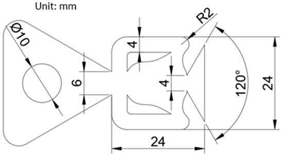
Figure 3.
Internal dimensions of the actuator.
2.3. Equipment and Measurement Instrumentation
A six-axis force–torque sensor (ATI Industrial Automation, Delta series) was mounted under the airfoil model to measure the aerodynamic loads. The measurement range of the sensor is shown in Table 1. The measuring precision of the sensor is as high as 1% of full scale (FS).

Table 1.
Measurement parameters of the force–torque sensor.
Sweeping jet actuator calibration was carried out using a miniature leadless dynamic pressure sensor (Kulite, XCL-072, Leonia, NJ, USA), which can measure the pressure range from 0 to 5 psi (5 psi is approximately 34,474 Pa) and can measure linear vibration from 0 to 2 kHz. The size of the pressure sensor is only Φ1.9 mm × 9.5 mm, which is suitable for the measurement of the sweeping jet actuator output. The sensor output signal was measured and processed with a dynamic signal test and analysis system (Donghua Testing Technology Company, DH5927N, Taizhou, China) with an analysis frequency width of 0–100 kHz. The dynamic signal test and analysis system have 8 input channels with the highest measurement frequency at 256 KHz/Ch and a 24-bit analog-to-digital converter. The uncertainty of the system is less than 0.5% (F.S), and the linearity is less than 0.1% (F.S). The sweeping jet actuator calibration set-up is shown in Figure 4.
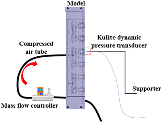
Figure 4.
Experimental set-up for the test of the sweeping jet actuator.
The airfoil surface dynamic pressure was measured using an in-house 64-channel pressure transducer (NUAA-GYS-5 at ±0.15 PSID pressure range and ±0.05% FS measurement accuracy). The pressure measurement system included a National Instruments data-acquisition system with a PXI-6284 module (18 bits, 0.98 mV absolute accuracy) to record the output voltage of the pressure transducers at an acquisition rate of 1 kHz. The entire pressure-measurement system was calibrated using a standard compensating micromanometer (Shanghai Meteorological Instrument Factory Co. Ltd., Shanghai, China, YJB-1500 at ±1500 Pa pressure range and ±0.8 Pa accuracy), and the measurement uncertainty was in the ±0.1% FS measurement range.
A compressed-air supplement system was also developed at the LLW. Two air tanks at 0.4 MPa in 8 m3 were used to provide compressed air for flow control. A high-precision mass flow controller (TSK621) with a range from 0 to 100 mLn/min, an accuracy of ±1.0% F.S, a linearity of ±0.5% F.S, and a response time of 1 s with a pressure regulating valve were used to regulate the flow rate of the sweeping jet actuators during the experiments. The experimental set-up in the wind tunnel is shown in Figure 5.
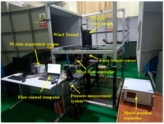
Figure 5.
Experimental set-up for the test in the wind tunnel.
3. Results and Discussion
3.1. Basic Characteristics of the Sweeping Jet Actuator
Before applying the sweeping jet actuator for the flow control on the supercritical airfoil, basic characteristics were first investigated. To explore the relationship between the mass flow rate of the supply air and the sweeping frequency of the actuator, the dynamic pressure sensor was installed at the outlet of the sweeping jet actuator to measure the jet-flow sweeping frequency, total pressure, and average velocity. By controlling the mass flow rate of the input air stream, the corresponding curve between mass flow rate and sweeping frequency can be constructed (see Figure 6); the sweeping frequency of the actuator increases with a rise in mass flow rate. The frequency varies from fjet = 460 Hz to 1500 Hz, while the mass flow rate varies from to respectively.
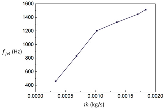
Figure 6.
Sweeping frequency of the sweeping jet for different mass flow rates.
The velocity at the throat of the sweeping jet actuator can be calculated according to the following formula:
where is the density of airflow at the throat of the actuator, is the area of the section at the throat, and is the velocity of the jet at the throat. Velocity and related total pressure measured by the dynamic-pressure transducer at the outlet are shown in Figure 7. The jet velocities of the sweeping jet actuator corresponding to the first three groups of mass flow rates are 34 m/s, 70 m/s, and 104 m/s, respectively; the sweeping frequencies corresponding to these groups are 460 Hz (), 830 Hz (), and 1200 Hz (). Correspondingly, the total pressure at the outlet increased with a rise in mass flow rate and velocity.
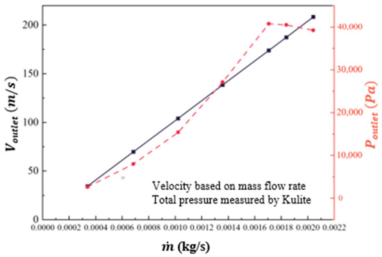
Figure 7.
The velocity and total pressure at the outlet.
3.2. Aerodynamic Characteristics of the NASA SC(2)-0410 2D Straight-Wing Model without Flow Control
The basic flow-field characteristics of the NASA SC(2)-0410 model were investigated using the calibration of the sweeping jet actuator. The lift coefficient of the model is defined according to the following formula:
where L is the lift of the wing model measured by the six-axis force–torque sensor, is the density of the incoming flow, is the velocity of the incoming flow, and S is the reference area of the wing model, respectively.
The lift and wing surface pressure data at different angles of attack (α) and flap deflection angles (δ) are shown in Figure 8.
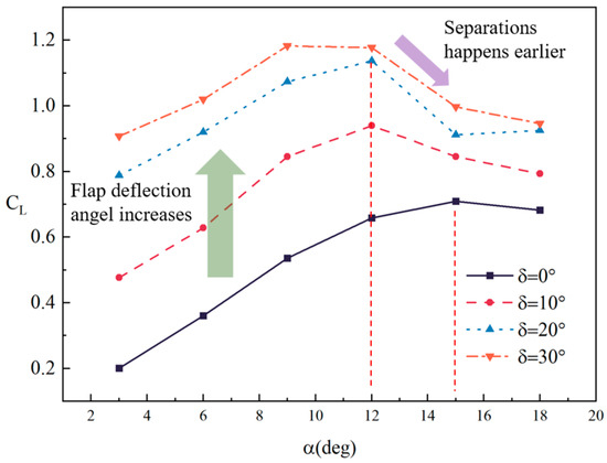
Figure 8.
Variation of lift coefficient with angle of attack (Re = 2.0 × 10⁵, V = 10 m/s).
It can be seen from the relationship between lift coefficient, angle of attack, and flap deflection angle in Figure 8 that the slope of the lift coefficient curve of the model starts to decrease beyond α = 9° without flap deflection (black line), which is caused by the local partly separated flow on the wing surface. However, with a continual increase in the angle of attack, the lift coefficient increases and reaches a maximum at α = 15°.
By analyzing the lift curves of different flap deflection angles, with an increase in the flap deflection angle, the lift coefficient of the wing can be significantly increased (dashed lines). For example, when the flap deflection angle changes to δ = 10°, the lift coefficient is increased by approximately 0.3, and the maximum lift coefficient changes from 0.7 (α = 15°) to 0.94 (α = 12°).
However, when the flap deflection changes from δ = 20° to δ = 30°, the lift yield decreases significantly, which indicates that there is a possible flow separation on the flaps at a lower angle of attack. In addition, at a high angle of attack, such as α = 9° and above, the benefit obtained by flap deflection is clearly less than that at low angles of attack.
To further analyze the flow field on the wing surface, the pressure data on the upper wing surface at different angles of attack and different flap deflection angles were further analyzed. The static characteristics of the wing surface pressure are expressed using the pressure coefficient, Cp, the calculation of which is shown as follows:
where is the wing surface pressure (measured from the pressure tappings), and and are the static and dynamic pressures of incoming flow, respectively. The upper-surface pressure distributions at different conditions are shown in Figure 9.
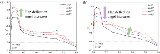
Figure 9.
Pressure coefficient for different percentage chord lengths of upper wing surface (Re = 2.0 × 10⁵, V = 10 m/s). (a) α = 9°. (b) α = 12°.
It can be seen from the pressure coefficient curve shown in Figure 9a, when α = 9°, that flap deflection can increase the negative pressure of the whole upper wing surface, especially in the leading edge area (i.e., as shown by the green arrow), which is one of the important sources of lift coefficient improvement in this situation. However, when the flaps are deflected from 20 to 30°, the pressure change of the main wing is relatively weak, and the pressure on the flaps even drops a little, which indicates that the flaps may have serious flow separation in this condition; it is difficult to obtain further lift by increasing the deflection angle at this point.
Furthermore, when α = 12°, flap deflection can decrease the negative pressure near the leading edge area of the upper wing surface (i.e., as shown by the puple arrow) but increase the negative pressure of the upper wing surface of the middle and aft area (i.e., as shown by the green arrow). In other words, the benefit of increased lift obtained by flap deflection is not obvious at this higher angle of attack.
3.3. Analysis of Aerodynamic Characteristics of the Wing Model with Sweeping Jet Control
In AFC, the momentum coefficient of the jet is a key dimensionless parameter to indicate the flow control effectiveness. In this paper, the following formula is used to calculate the momentum coefficient:
where is the total mass flow rate used for flow control, is the gas density at the outlet throat of the actuator, is the area at the outlet throat of the actuator, is the dynamic pressure, and is the reference area of the wing.
According to Equation (4), the momentum coefficients corresponding to the three groups of mass flow rate are 0.9% (), 3.7% (), and 8.2% (), respectively.
Figure 10 shows the wing lift coefficient and lift increment for different momentum coefficients of the sweeping jet when the flap deflection angle is fixed at the maximum position, δ = 30°.
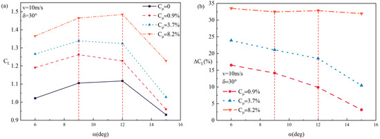
Figure 10.
Variation of lift coefficient of the wing model with angle of attack for different momentum coefficients (δ = 30°, Re = 2.0 × 10⁵, V = 10 m/s). (a) Lift coefficient at different angles of attack. (b) Variation of lift coefficient with angle of attack.
It can be seen from the figure that the flow control for the three groups of momentum coefficients can produce significant lift increments at both angles of attack under testing. With an increase in the angle of attack, the flow-control effect at a small momentum coefficient gradually weakens. This may be caused by the large angular deflection of the flaps at high angles of attack, causing flow separation to occur on the main wing, which reduces the efficacy of the sweeping jet flow. However, when the momentum coefficient reaches 8.2%, the increase in the lift coefficient of the sweeping jet can be maximized to ΔCL = 34% @ α = 6°; also, it remains greater than 30% over the full range of the angle of attack, which indicates that a jet injection with large energy can not only inhibit separation flow on the flap but also have a significant effect on the flow field over the main wing surface.
To study the mechanism and influence of flow control in more detail, the surface pressure data on the upper wing surface are analyzed for the condition after the jet flow is applied, which is shown in Figure 11.
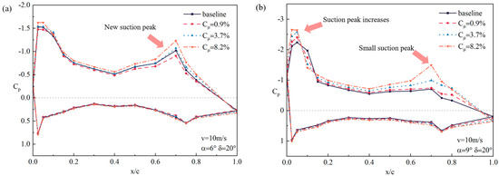
Figure 11.
Pressure coefficient on the upper wing surface at different momentum coefficients (δ = 30°, Re = 2.0 × 10⁵, V = 10 m/s). (a) α = 6°. (b) α = 9°.
The wing surface pressure coefficient curve shows that before stall, sweeping jet AFC benefits are mainly attributable to the “new” strong peak of pressure in the flap position (i.e., x/c = 0.7), which inhibits the generation of flow separation. In addition, the negative pressure on the main wing surface is increased by the sweeping jet, and the suction peak near the leading edge is increased.
However, when the angle of attack is increased to α = 9°, only the flow control at Cμ = 8.2% has a peak of pressure on the flaps (i.e., the red dash-dot line), which indicates that the sweeping jet with a small momentum coefficient cannot effectively change the flow field on the flaps. This is the main factor for the reduction in the control effect of the sweeping jet with a small momentum coefficient. In addition, owing to the introduction of a high-speed sweeping jet, flow separation at the leading edge of the main wing is partly inhibited, and the suction peak increases slightly (as shown in Figure 11b), which is the main reason why the sweeping jet can still produce a control effect in this condition.
4. Conclusions
In this paper, a two-dimensional straight-wing model of the supercritical airfoil NASA SC(2)-0410 was used to study the flow-control effect of sweeping jets with different momentum coefficients at Re = 2.0 × 10⁵ (V = 10 m/s). Based on the experimental results, the aerodynamic performance of the wing model and flow-separation characteristics of the wing flap have been demonstrated. The flow control effectiveness and control mechanism of sweeping jets on the model were investigated, and specific conclusions are as follows:
- A large angular deflection of a simple flap causes flow separation on the upper surface of the wing and flap, which limits further improvement in the wing lift coefficient using only flap deflection during the takeoff stage.
- The lifting effect of the sweeping jet flow control is enhanced with the increase in the jet momentum coefficient of the sweeping jet. In this study, the flow control based on the sweeping jet actuator can generate a maximum increase of approximately 33% in the lift coefficient of the wing model with Cμ = 8.2%.
- The use of a sweeping jet at the front of the flap can effectively improve the lift coefficient of the whole wing, which comes from the extra lift generated by the jet at the flap and from the greater negative pressure near the leading edge on the upper wing surface owing to the induced flow caused by the sweeping jet.
The research results of this paper will help engineers and researchers understand how to better optimize the high-lift system during the takeoff stage and provide validation data for the flow control technology design and CFD simulation on AFC technology.
Author Contributions
Conceptualization, K.C. and Y.G.; methodology, L.L.; formal analysis, S.L.; investigation, S.L. and R.F.; resources, W.W.; writing—original draft preparation, S.L.; writing—review and editing, L.L. and S.L.; funding acquisition, Y.G. and W.W. All authors have read and agreed to the published version of the manuscript.
Funding
This research was funded by the Civil Aircraft Research Projects and the Priority Academic Program Development of Jiangsu Higher Education Institutions.
Institutional Review Board Statement
Not applicable.
Informed Consent Statement
Not applicable.
Data Availability Statement
The data presented in this study are available on request from the corresponding author.
Acknowledgments
The authors would like to thank all those who participated in the study, including Tong Zhao, Yalei Bai, and Rong Sun.
Conflicts of Interest
The authors declare no conflict of interest.
Nomenclature
| The area of the section at the throat of the actuator. | |
| c | Wing chord length. |
| CL | The lift coefficient of the model. |
| Cp | The surface pressure coefficient of the model. |
| Cμ | The momentum coefficient of the sweeping jet. |
| d | Spanwise spacing distance of the actuators. |
| fjet | The frequency of the sweeping jet. |
| l | Wing span. |
| L | The lift of the wing model. |
| The mass flow rate of the sweeping jet. | |
| The static pressure of the incoming flow. | |
| The dynamic pressure of the incoming flow. | |
| Re | Reynold number. |
| S | The reference area of the wing model. |
| V | The velocity of incoming flow. |
| Vjet | The velocity of the jet at the throat of the actuator. |
| α | Angle of attack. |
| δ | Flap deflection angle. |
| The density of the incoming flow. | |
| The density of airflow at the throat of the actuator. |
References
- Batikh, A.; Baldas, L.; Colin, S. Application of active flow control on aircrafts—State of the art. In Proceedings of the International Workshop on Aircraft System Technologies, Hamburg, Germany, 21–22 February 2017. [Google Scholar]
- Van Dam, C.P. The aerodynamic design of multi-element high-lift systems for transport airplanes. Prog. Aerosp. Sci. 2002, 38, 101–144. [Google Scholar] [CrossRef]
- Loftin, K.L. Quest for Performance: The Evolution of Modern Aircraft; NASA-SP-468; Scientific and Technical Information Branch, National Aeronautics and Space Administration: Newport News, VA, USA, 1985. [Google Scholar]
- McLean, J.; Crouch, J.; Stoner, R.; Sakurai, S.; Seidel, G.E.; Feifel, W.M.; Rush, H.M. Study of the Application of Separation Control by Unsteady Excitation to Civil Transport Aircraft; NASA/CR-1999-209338; National Aeronautics and Space Administration: Hampton, VA, USA, 1999. [Google Scholar]
- Kiedaisch, J.; Nagib, H.; Demanett, B. Active flow control applied to high-lift airfoils utilizing simple flaps. In Proceedings of the 3rd AIAA Flow Control Conference, San Francisco, CA, USA, 5–8 June 2006. [Google Scholar]
- Pack Melton, L.G.; Koklu, M. Active flow control using sweeping jet actuators on a semi-span wing model. In Proceedings of the 54th AIAA Aerospace Sciences Meeting, San Diego, CA, USA, 4–8 January 2016. [Google Scholar] [CrossRef]
- Cao, X.; Dong, H.; Gu, Y.; Cheng, K.; Zhang, F. Experimental Study of Vertical Tail Model Flow Control Based on Oscillating Jet. Appl. Sci. 2023, 13, 786. [Google Scholar] [CrossRef]
- Raman, G.; Raghu, S. Cavity resonance suppression using miniature fluidic oscillators. AIAA J. 2004, 42, 2608–2612. [Google Scholar] [CrossRef]
- DeSalvo, M.; Whalen, E.; Glezer, A. High-Lift Performance Enhancement Using Active Flow Control. AIAA J. 2020, 58, 4228–4242. [Google Scholar] [CrossRef]
- Tomac, M.N.; Hossain, M.A. Flow and Frequency Characterization of the Synchronized Stacked Sweeping Jets. AIAA J. 2021, 59, 118–130. [Google Scholar] [CrossRef]
- Serrar, A.; Khlifi, M.; Kourta, A. Characterisation and comparison of unsteady actuators: A fluidic oscillator and a sweeping jet. Int. J. Numer. Methods Heat Fluid Flow 2022, 32, 1237–1254. [Google Scholar] [CrossRef]
- Mohammadshahi, S.; Samsam-Khayani, H.; Deng, Z. Experimental investigation of flow dynamics of oscillating jet emitted in confined and non-confined backward-facing step geometries. Eur. J. Mech.-B/Fluids 2021, 88, 89–102. [Google Scholar] [CrossRef]
- Song, J.; Wang, S.; Wen, X.; Li, Z.; Lu, H.; Kong, X.; Liu, Y. Active flow control in an S-shaped duct at Mach 0.4 using sweeping jet actuators. Exp. Therm. Fluid Sci. 2022, 138, 110699. [Google Scholar] [CrossRef]
- Alexander, M.G.; Harris, F.K.; Spoor, M.; Boyland, S.R.; Farrell, T.; Raines, D. Active Flow Control (AFC) and Insect Accretion and Mitigation (IAM) system design and integration on the Boeing 757 ecoDemonstrator. In Proceedings of the 16th AIAA Aviation Technology, Integration, and Operations Conference, Washington, DC, USA, 13–17 June 2016. [Google Scholar] [CrossRef]
- Greenblatt, D.; Wygnanski, I. The control of flow separation by periodic excitation. Prog. Aerosp. Sci. 2000, 36, 487–545. [Google Scholar] [CrossRef]
- Hartwich, P.M.; Camacho, P.; El-Gohary, K.; Gonzales, A.B.; Lawson, E.L.; Shmilovich, A. System-level trade studies for transonic transports with Active Flow Control (AFC) enhanced high-lift systems. In Proceedings of the 55th AIAA Aerospace Sciences Meeting, Grapevine, TX, USA, 9–13 January 2017. [Google Scholar]
- Shmilovich, A.; Yadlin, Y.; Dickey, E.D.; Hartwich, P.M.; Khodadoust, A. Development of an active flow control technique for an airplane high-lift configuration. In Proceedings of the 55th AIAA Aerospace Sciences Meeting, Grapevine, TX, USA, 9–13 January 2017. [Google Scholar]
- Jones, G.S.; Milholen, W.E.; Chan, D.T.; Goodliff, S.L. A sweeping jet application on a high Reynolds number semi-span supercritical wing configuration. In Proceedings of the 35th AIAA Applied Aerodynamics Conference, Denver, CO, USA, 5–9 June 2017. [Google Scholar]
- Melton, L.P.; Koklu, M.; Andino, M.; Lin, J.C. Active flow control via discrete sweeping and steady jets on a simple-hinged flap. AIAA J. 2018, 56, 2961–2973. [Google Scholar] [CrossRef]
- Vatsa, V.N.; Duda, B.M.; Lin, J.C.; Pack Melton, L.G.; O’Connell, M. Numerical simulation of a simplified high-lift CRM configuration embedded with fluidic actuators. In Proceedings of the 2018 Applied Aerodynamics Conference, Atlanta, GA, USA, 25–29 June 2018. [Google Scholar]
- Koklu, M.; Pack Melton, L.G.; Lin, J.C.; Hannon, J.; Andino, M.; Paschal, K.; Vatsa, V.N. Surface flow visualization of the high lift common research model. In Proceedings of the AIAA Aviation 2019 Forum, Dallas, TX, USA, 17–21 June 2019. [Google Scholar]
- Pack Melton, L.G.; Lin, J.C.; Hannon, J.; Koklu, M.; Andino, M.; Paschal, K.B. Sweeping jet flow control on the simplified high-lift version of the common research mode. In Proceedings of the AIAA Aviation 2019 Forum, Dallas, TX, USA, 17–21 June 2019. [Google Scholar]
- Vatsa, V.N.; Duda, B.M.; Lin, J.C.; Pack Melton, L.G.; Lockard, D.P.; O’Connell, M.; Hannon, J. Comparative study of active flow control strategies for lift enhancement of a simplified high-lift configuration. In Proceedings of the AIAA Aviation 2019 Forum, Dallas, TX, USA, 17–21 June 2019. [Google Scholar]
- Lin, J.C.; Pack Melton, L.G.; Hannon, J.; Andino, M.Y.; Koklu, M.; Paschal, K.C.; Vatsa, V.N. Wind tunnel testing of High Efficiency Low Power (HELP) actuation for active flow control. In Proceedings of the AIAA Scitech 2020 Forum, Orlando, FL, USA, 6–10 January 2020. [Google Scholar]
- Lin, J.C.; Melton, L.P.; Hannon, J.A.; Andino, M.Y.; Koklu, M.; Paschal, K.B.; Vatsa, V.N. Testing of high-lift common research model with integrated active flow control. J. Aircr. 2020, 57, 1121–1133. [Google Scholar] [CrossRef]
- Baghaei, M.; Bergada, J.M. Fluidic Oscillators, the Effect of Some Design Modifications. Appl. Sci. 2020, 10, 2105. [Google Scholar] [CrossRef]
- Samsam-Khayani, H.; Mohammadshahi, S.; Kim, K.C. Experimental Study on Physical Behavior of Fluidic Oscillator in a Confined Cavity with Sudden Expansion. Appl. Sci. 2020, 10, 8668. [Google Scholar] [CrossRef]
- Awate, V.G.; Ansell, P.J. Characterization of Inclined Oscillating Jet and Crossflow Interaction for Use in Active Flow Control. In Proceedings of the AIAA SciTech Forum, Orlando, FL, USA, 6–10 January 2020. [Google Scholar] [CrossRef]
- Ostermann, F.; Woszidlo, R.; Nayeri, C.; Paschereit, C.O. Interaction Between a Crossflow and a Spatially Oscillating Jet at Various Angles. AIAA J. 2020, 58, 2450–2461. [Google Scholar] [CrossRef]
- Fromm, M.; Kim, J.; Seifert, A.; Kriegseis, J.; Grundmann, S. Flow Patterns of Self-Sustained Oscillations in Fluidic Diverters. AIAA J. 2022, 60, 4207–4214. [Google Scholar] [CrossRef]
- Koklu, M. The effects of sweeping jet actuator parameters on flow separation control. In Proceedings of the 45th AIAA Fluid Dynamics Conference, Dallas, TX, USA, 22–26 June 2015. [Google Scholar]
Disclaimer/Publisher’s Note: The statements, opinions and data contained in all publications are solely those of the individual author(s) and contributor(s) and not of MDPI and/or the editor(s). MDPI and/or the editor(s) disclaim responsibility for any injury to people or property resulting from any ideas, methods, instructions or products referred to in the content. |
© 2023 by the authors. Licensee MDPI, Basel, Switzerland. This article is an open access article distributed under the terms and conditions of the Creative Commons Attribution (CC BY) license (https://creativecommons.org/licenses/by/4.0/).