Abstract
A number of apple trees have collapsed in South Korea due to strong winds caused by typhoons. In fact, apple trees are protected by various types of support systems. However, despite this, they have still been damaged. The reason why the trees collapsed is that the installation of a support system is based not on scientific facts but on empirical facts. The purpose of this study was to evaluate the structural safety of the anti-disaster support system of apple trees. Equivalent static tests of the support systems, i.e., fences and matrix supports, were carried out. The result of the equivalent static tests indicated that the bearing capacity of the foundation is considered an important factor for the performance of the fence support, and the elements played a major role in the case of the matrix support due to the connection of the strut wire and the mat wire. Based on this test result, design criteria and standard specifications of the apple tree support system in response to local wind speed are proposed.
1. Introduction
Recent weather anomalies with increased typhoon occurrence are causing increased damage to orchards. In particular, the falling of apples and collapse of apple trees just prior to harvest time leads to a great economic loss for farmers. This calls for effective orchard management and precaution against typhoon disasters. Although there are many types of support systems for apples in South Korea, the design and construction of support systems have been mainly carried out heuristically by experienced farmers, not scientifically by engineers, due to the poor economic conditions of the orchards. Hence, typhoon damage to apple trees still repeats year after year. Therefore, the improvement in the types of support system for apple trees has been investigated domestically and abroad. Various support systems and structures to prevent damage from typhoons have been used in South Korea [1]. A study was conducted to analyze the elevation to calculate the wind load acting on apple trees for the design of a pipe support [2], and the structural analysis of an orchard with a fence-type apple tree support facility was performed to evaluate its stability [3]. In addition, the integration behavior was evaluated by analyzing the bonding strength of a clamp for connection between an apple tree and its support [4].
The support systems of orchards over the last 50 years have changed dramatically. Individual support, steel pipe fence support, and concrete fence support can be cited as the three typical types of apple tree support systems. Robinson et al. [5] estimated that tall spindles are the current and future best support system for apple orchards because of the advantage of using a narrower canopy maintained by mechanical side wall shearing to reduce labor costs and improve fruit quality. In Australia, V trellis, Tatural trellis, and Spindlebush systems have been used to increase the productivity and performance of apple orchards by maintaining a narrow canopy depth in all directions [6]. However, these support systems have been introduced from regions where strong tropical typhoons do not take place [7], and the majority of the research on support systems has focused on annual fruit productivity and the subsequent profit from it [8,9]. Thus, it is necessary to develop a support system for apple trees that is conducive to the domestic situation through an accurate evaluation of its capacity to resist wind load. Therefore, this paper presents static tests and design procedures for an anti-disaster-type support that can prevent overturning moment damage to apple trees based on the maximum wind speed for each region in South Korea.
2. Anti-Disaster Support System
2.1. Fence and Matrix Support
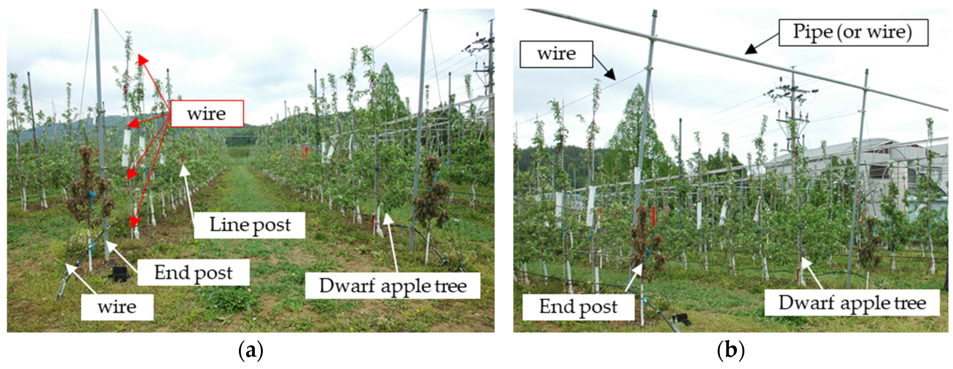
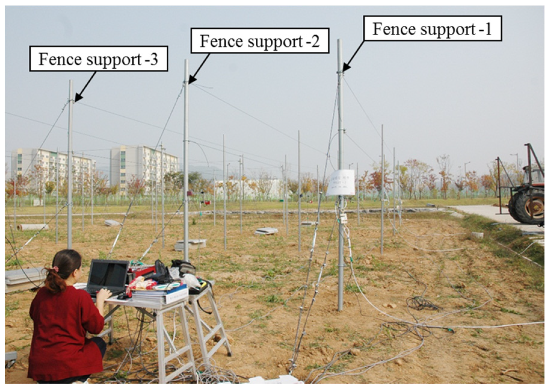
In this paper, experiments and design were conducted for two types of dwarf apple tree support systems, as shown in Figure 1.
Figure 1a is a fence support system in which steel pipes are installed at intervals of three (or four) apple trees and connected to the trunk of an apple tree through four wires connected between the pipes for support. Figure 1b is a matrix support system in which individual fence systems are connected with steel pipes (or wires) at top of pipe to ensure the same behavior. The fence support system is similar to the tall spindle orchard system, connecting the slender spindles of each apple tree with trellis wire. The overall behavior is controlled by steel pipes to resist horizontal loads such as strong winds and typhoons.
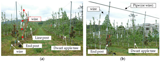
Figure 1.
Anti-disaster support system: (a) fence support; (b) matrix support.
2.2. Test Set-Up
This study performed an equivalent static test on an actual support system in order to evaluate its resistance capacity for apple trees against wind load. The field test was performed on a fence support and a matrix support. The front view of the fence and matrix support was the same as in Figure 2. A dwarf apple tree grows up to 6 to 12 feet tall (equal to 1.8 to 3.6 m) and needs a spacing of 6 to 8 feet (equal to 1.8 to 2.4 m) [10]. Therefore, a plan was made to install one line post for every three dwarf apple trees and support posts with a height of 3.2 m at 6 m intervals. The matrix support was made up of three fence supports in parallel to one another and affixed with matrix horizontal wires (mat wire, ø3.97). The spacing between rows of apple trees was wider than the spacing between apple trees in order to increase workability and productivity. In the matrix support system, it was set to 4 m to secure sufficient space for the worker.
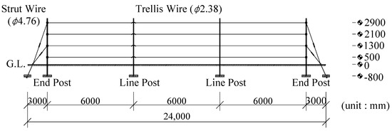
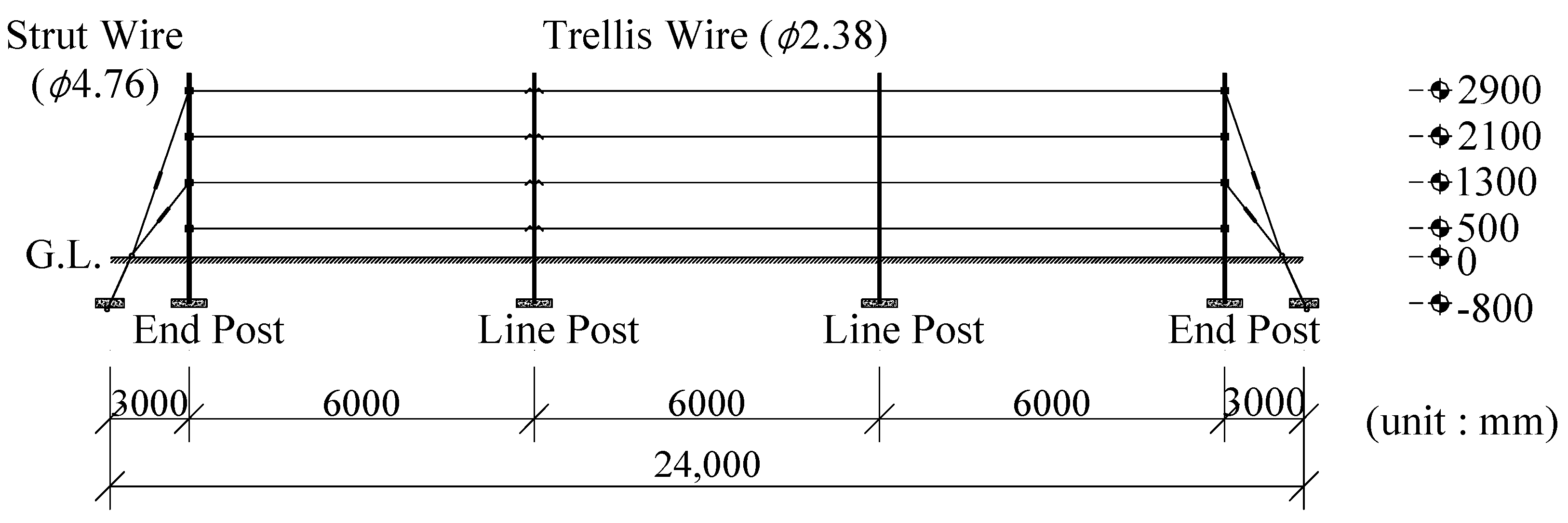
Figure 2.
Front view of fence and matrix support systems.
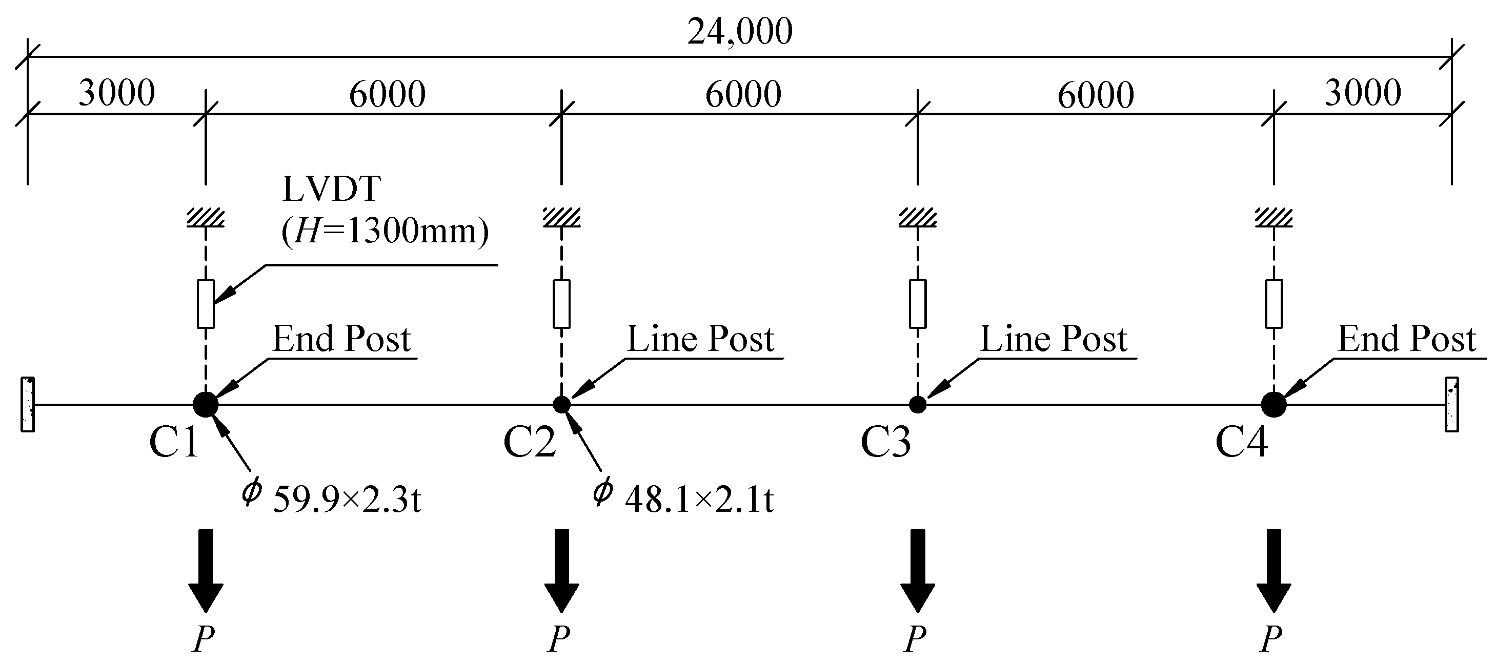
Figure 3 and Figure 4 show ground plans of the fence support and matrix support, respectively, where load represents the loading direction. The fence support connected the end post (ø59.9 × 2.3t) and line post (ø48.1 × 2.1t) with four trellis wires (ø2.38), and two strut wires (ø4.76) were additionally used to tighten the support to the ground at both ends. Since the actual wind load fluctuated randomly and was hard to apply to the field site, it was simulated by installing chain blocks to each support with connection hardware based on the principle of a pulley. The loading point of the fence support was 1300 mm above the ground, and the load cell and linear variable displacement transducer (LVDT) were installed on each support at the same height.

Figure 3.
Plane view of the fence support system.
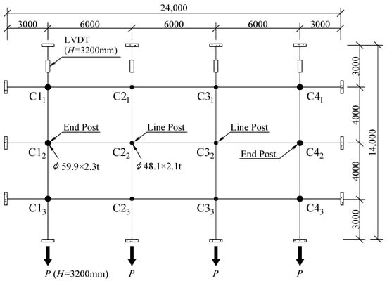
Figure 4.
Plane view of the matrix support system.
Meanwhile, the matrix support had the load cell and LVDT installed at a height of 3200 mm above ground because of the concern over early ending of the experiment due to the bending of the support at mid-height when loads were applied at a height of 1300 mm. To measure the deformation of the support, LVDTs were installed in the support test system using a magnetic base.
3. Equivalent Static Test
3.1. Material Properties
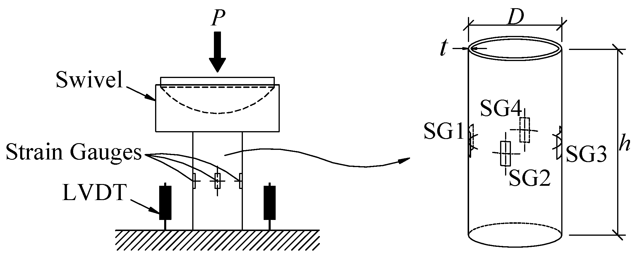
Specimens with cross-sectional specifications of ø48.1 × 2.1 and ø59.9 × 2.3 were cut from the apple tree support system to determine the mechanical properties of the steel material. The specimens were subjected to a stub column test, as shown in Figure 5.

Figure 5.
Conceptualization of the stub column test.
The LVDT installation was located parallel to the specimen to measure the latter’s vertical displacement. Additionally, four one-axis strain gauges were installed around the column center, where concentrated stress is expected, to examine the strain of the column. Moreover, a universal test machine was used to apply one-axis loading on the column, and a swivel was installed to prevent the column’s eccentricity.
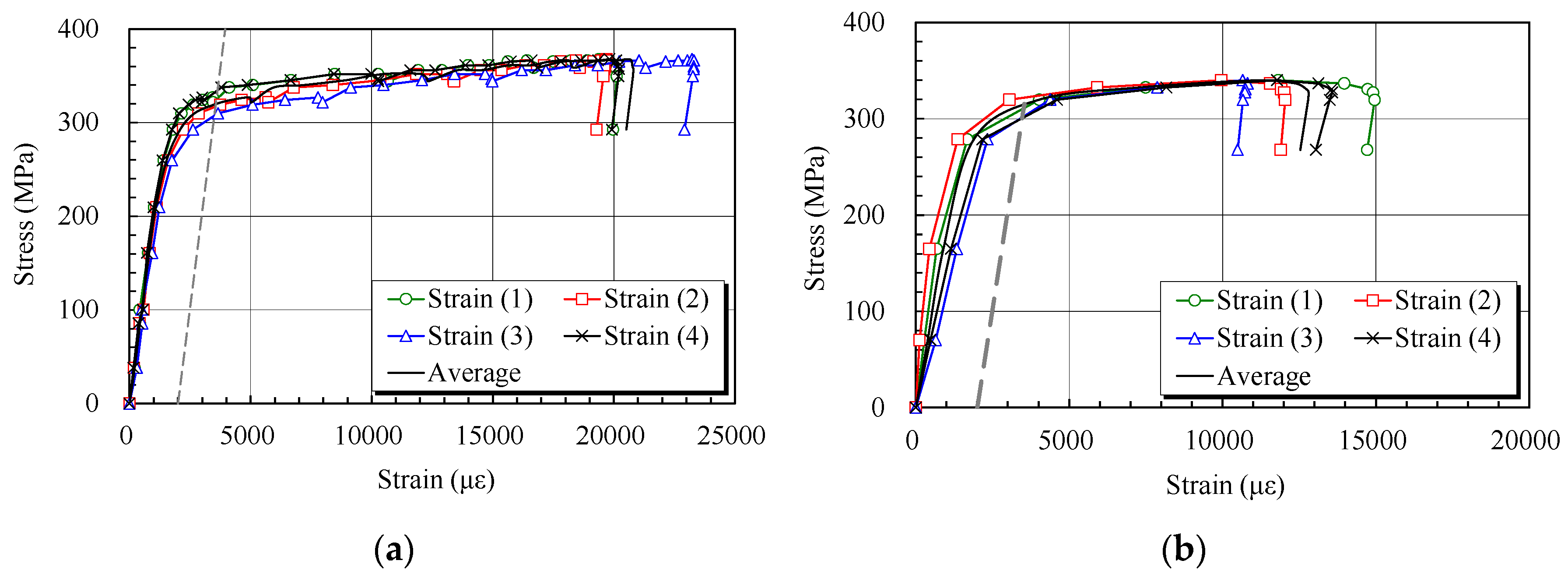
Figure 6 shows stress–strain relationship curves, which were obtained from the stub column test of the support pipe for apple trees. Measuring the yield strength of the support pipe with the 0.002 (or 0.2%) offset method, the yield and tensile strength of the ø48.1 × 2.1 specimen were 320.0 Mpa and 367.7 Mpa, respectively, while those of the ø59.9 × 2.3 specimen were 315.5 Mpa and 339.9 Mpa, respectively. These yield strengths measured in the stub column test were relatively higher than the yield strength of 295 Mpa [11] of the support pipe (SPVHS) used in this study.
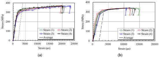
Figure 6.
Stress–strain relationship of steel pipes: (a) cross section was ø48.1 × 2.1; (b) ø59.9 × 2.3.
For this study, a total of three fence supports and two matrix supports were prepared. Section properties of the end post and line post of both the fence and matrix supports are shown in Table 1. The failure load of the apple tree support system is considered to be the displacement of the apple tree. The displacement in response to the failure load was computed in consideration of the result of the apple tree collapse test [12]. The displacement at the LVDT measuring point of the fence and matrix support test was compared to the displacement at the maximum load of the apple tree collapse test that was carried out previously. The displacement of the apple tree collapse test was measured with the LVDT at a height of 1100 mm above ground, and the average angle of the apple tree collapse was measured as 10.4°. Based on the result, the collapse displacements of the fence support and matrix support were computed to be 238.59 mm and 587.31 mm, respectively, in this study.

Table 1.
Section properties of members.
Table 2 shows that the modulus of elasticity of the posts was 200,000 MPa based on the stress–strain curve. Additionally, the yield moments of the line post and end post calculated by the nominal yield strength of the SPVHS were 986.6 kN and 1702.8 kN, respectively. At the yield moment, since the loading point of the line and end posts of the fence support was 1300 mm, their yield loads were 758.9 N and 1309.8 N, respectively. The loading point of the line and end posts of the matrix support was 3200 mm above the ground, and the yield loads were 308.33 N and 532.14 N, respectively. The values represent the performance of each line and end post of the matrix support. However, because the matrix support was made up of three fence supports in parallel to one another, the yield loads of the line and end posts should be multiplied by 3. Therefore, the yield loads of the line and end posts were computed to be 924.9 N and 1596.4 N, respectively.
Table 2.
Section properties of post (SPVHS).
3.2. Fence Support System
Figure 7 shows the test set-up of the fence support system. Assuming that the wind load acting on the apple tree was transferred from the wire supporting the tree to the line and end post, an equivalent static test was performed by pulling each post. Loading was applied while continuous monitoring of the load cell and LVDT was performed in order to prevent eccentricity. The collapse test of the fence support was carried out to induce the displacement of the apple tree collapse (over 238.59 mm). When the first test type collapsed, it was removed to subject the next support to the collapse test, and the procedure was repeated. Figure 8 presents the failure mode of the fence support right after the collapse test. It shows the collapse of the line post and end post due to loading.
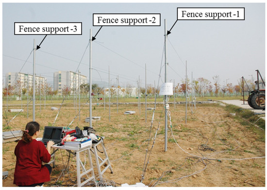
Figure 7.
View of the fence support system.
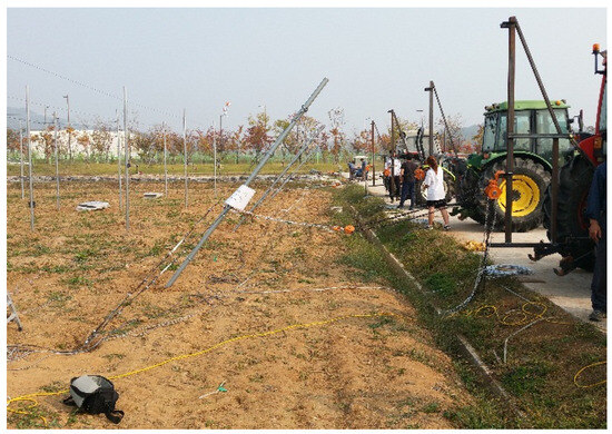
Figure 8.
Test of the fence support system.
Figure 9 shows the ground condition and the plastic hinge of the support after collapse. As loading increased, the support was damaged by the plastic hinge after yielding. The plastic hinge of the line post was more conspicuous in comparison to that of the end post, as shown by the test result.
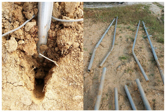
Figure 9.
Ground state and plastic hinge.
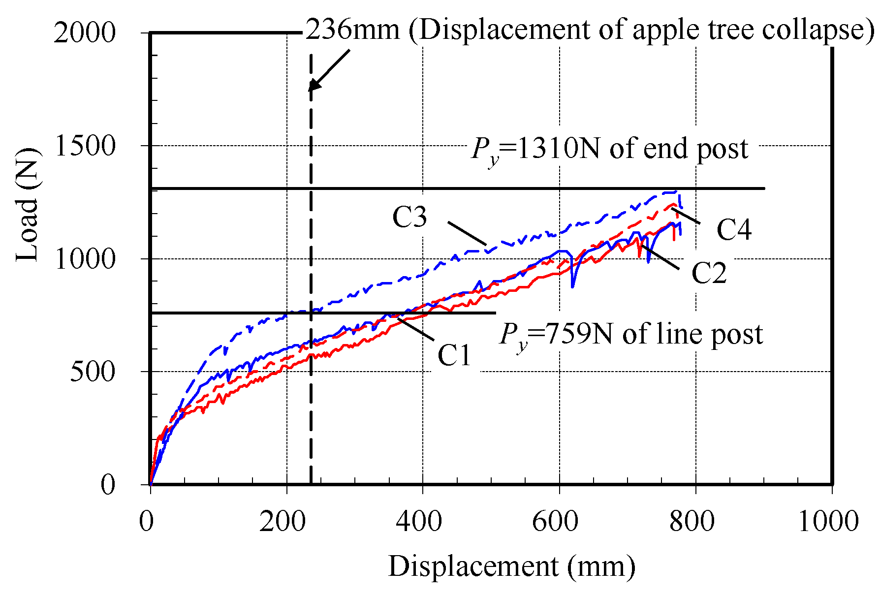
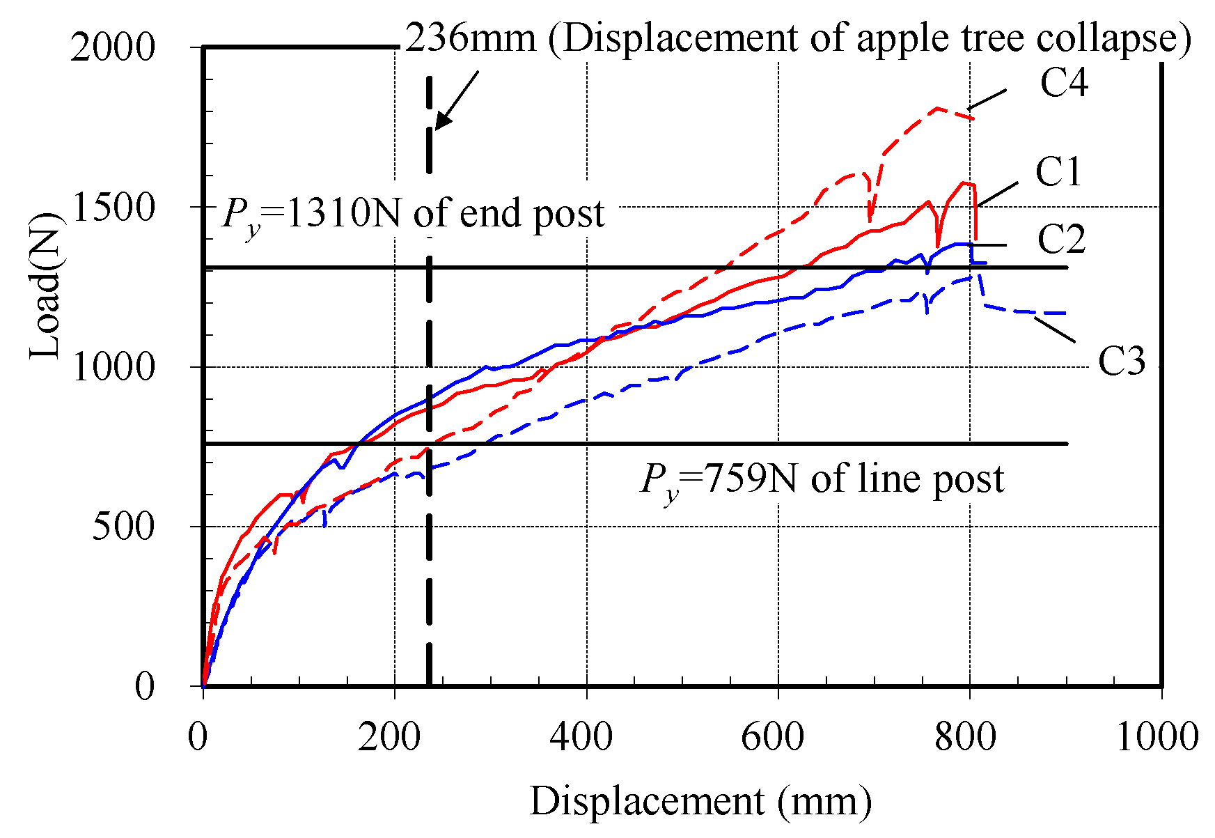
Figure 10, Figure 11 and Figure 12 show load–displacement curves for the three fence support types. Using the yield loads of the line post (759 N) and end post (1310 N), each fence support system was examined for whether it had reached the yield load after the performance test.
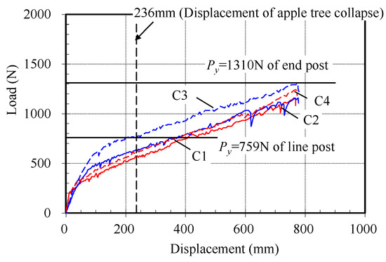
Figure 10.
Test result of fence support 1.
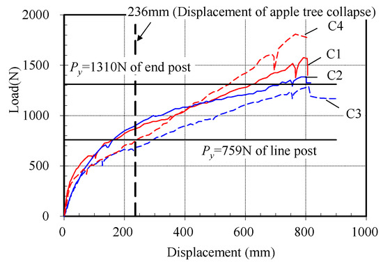
Figure 11.
Test result of fence support 2.
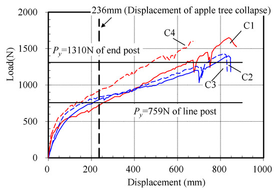
Figure 12.
Test result of fence support 3.
Figure 10 shows that a line post (C3) reached the yield load at the displacement of the apple tree collapse, whereas other line posts (C2) and end posts (C1 and C4) did not. In particular, the first fence support test manifested a lack of bearing capacity of the ground. This is explained by the tractor compaction of the ground for the first test type not being satisfactory because the location was near drainage. Generally, the line and end posts of the first support test exhibited linear behavior up to 500 N. As the load increased, a second linear behavior was observed prior to reaching the yield load due to the aforementioned lack of bearing capacity of the ground. The test ended at the load above the yield load to observe the plastic hinge behavior of the support pipe. However, the displacement had already reached over the displacement at the time of apple tree collapse, requiring the consideration for reducing effect of the ground condition state during the design of the support system. Therefore, the linear trend around the load of 455 N (60% of the yield load for line post) was to be applied in consideration of the bearing capacity of the ground for the case of the line post. Although the end post manifested the same first linear trend as the line post, it exhibited a load of 786 N, which was 60% of the yield load for the end post, at the same displacement of the apple tree collapse. Therefore, the same reduction in the yield load as the line post was applied during the design of the end post system.
3.3. Matrix Support System
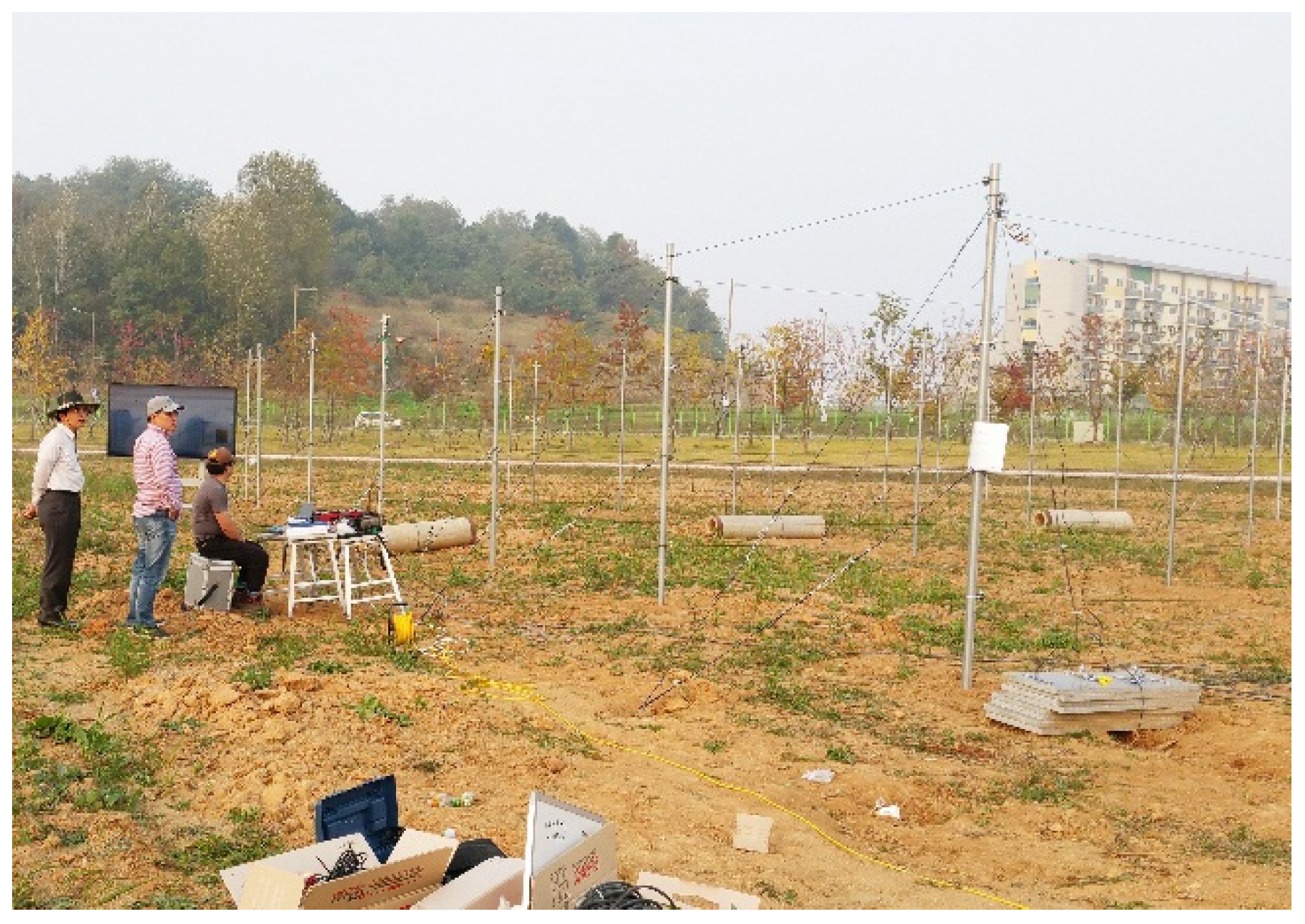
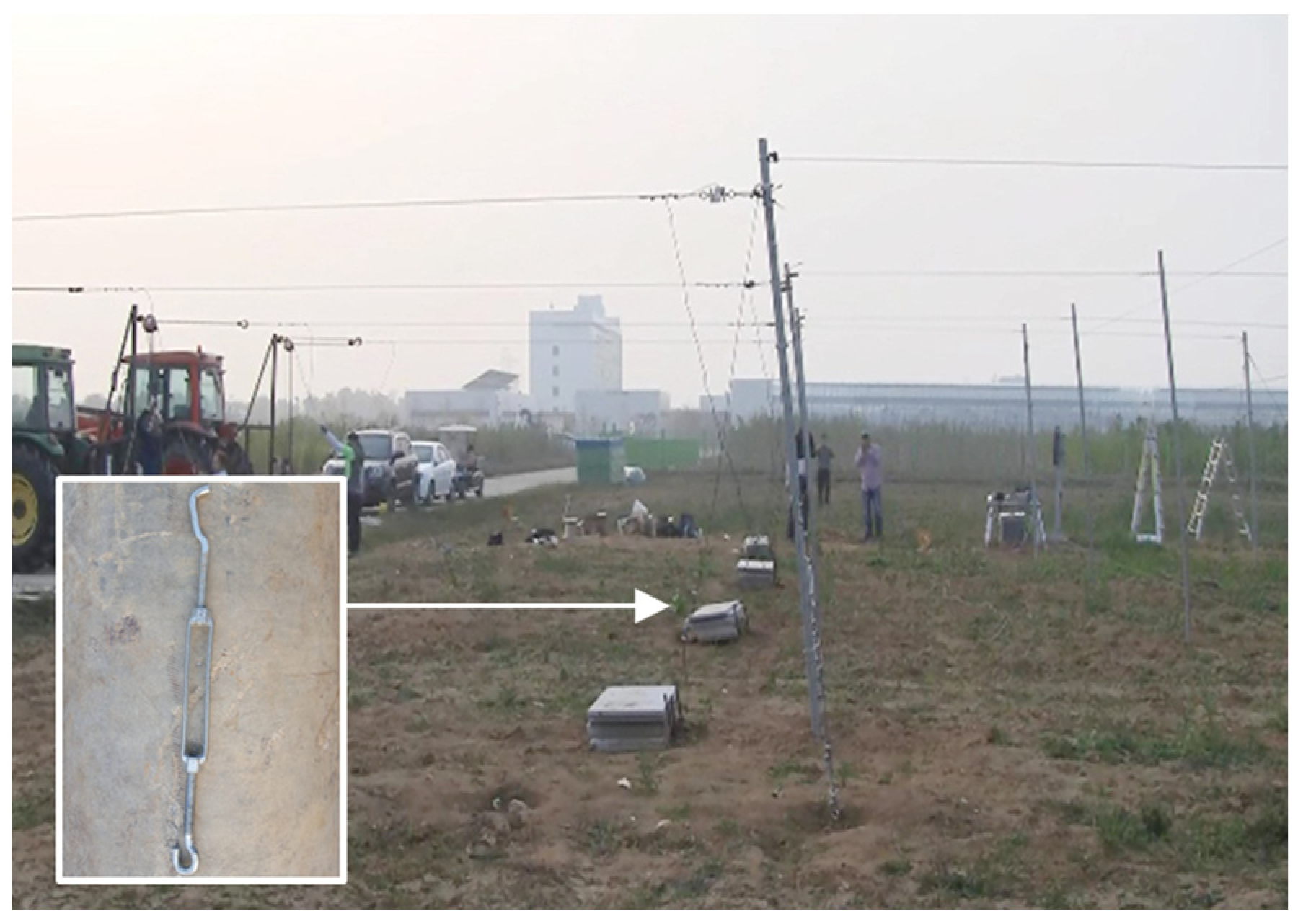
Figure 13 shows the test set-up of the matrix support system. The performance test of the matrix support involved the same procedure as the fence performance test. When the first test type collapsed, it was removed to test on the next test type until it collapsed. The performance test of the matrix support system continued up to the point of displacement, 587.31 mm at the time of the apple tree collapse. Figure 14 shows the inducing of the collapse of the first matrix support. The test ended abruptly due to the yielding of the hook of a 3/8 inch turnbuckle. Consequently, this study suggests the use of a 1/2 inch turnbuckle.
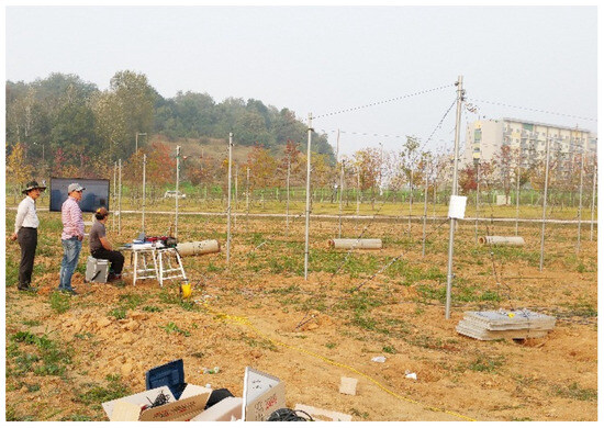
Figure 13.
View of the matrix support system.
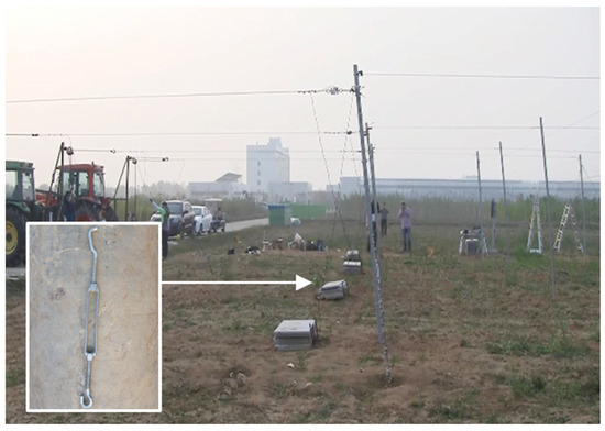
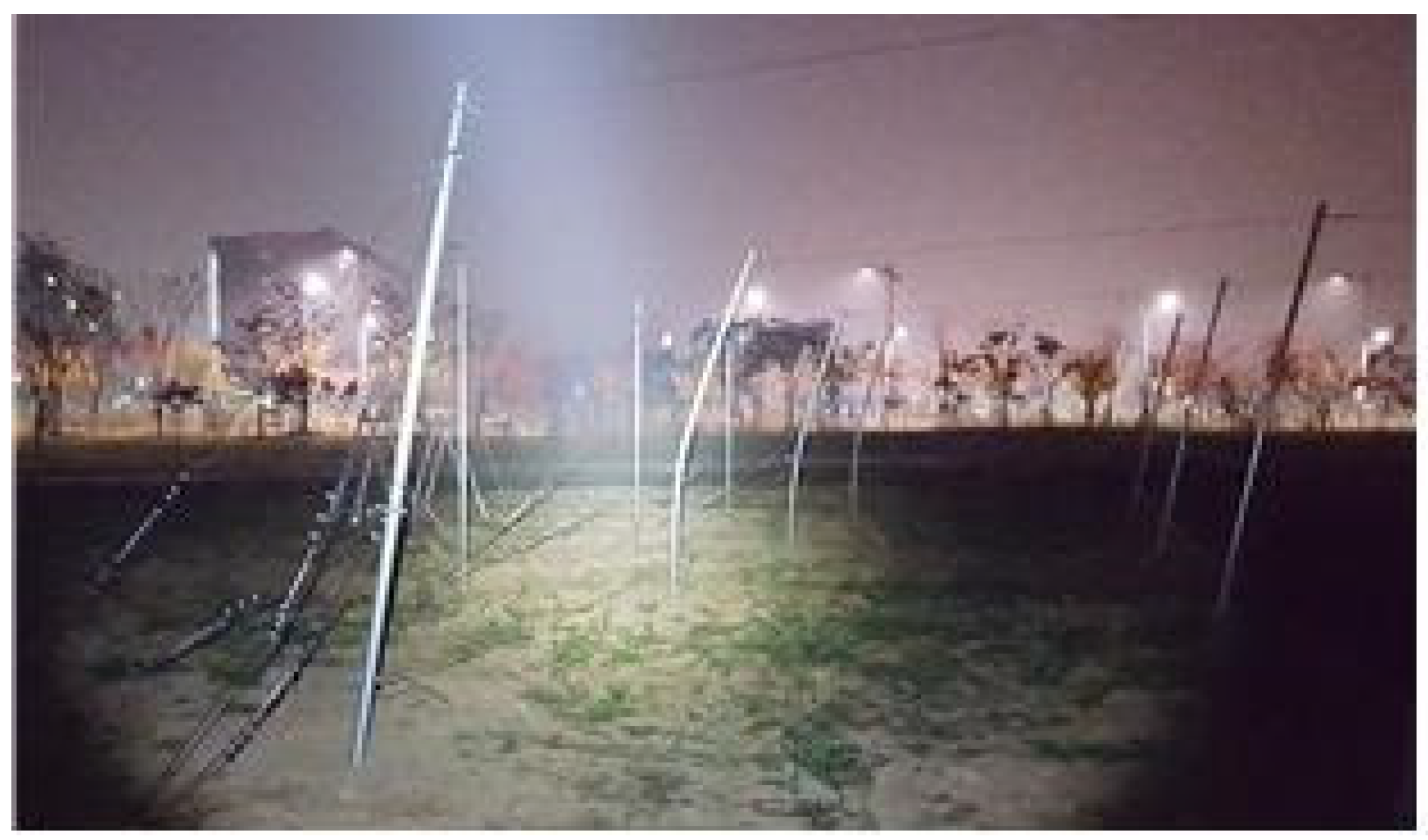
Figure 14.
Test of the matrix support system.
Figure 15 shows the plastic hinge taking place at the line post as a result of the collapse test. The plastic hinge of the matrix support occurred at the height of the strut wire in the loading direction, unlike that of the fence support. Considering that the basic bearing support force is an important factor of the fence support to manifest its performance capacity, the factor of connection between the strut wire and the matrix horizontal wire (mat wire) exerted a great influence for the case of the matrix support.
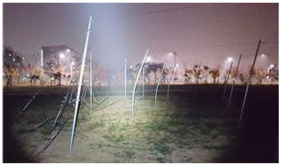
Figure 15.
Plastic hinge formed on the posts.
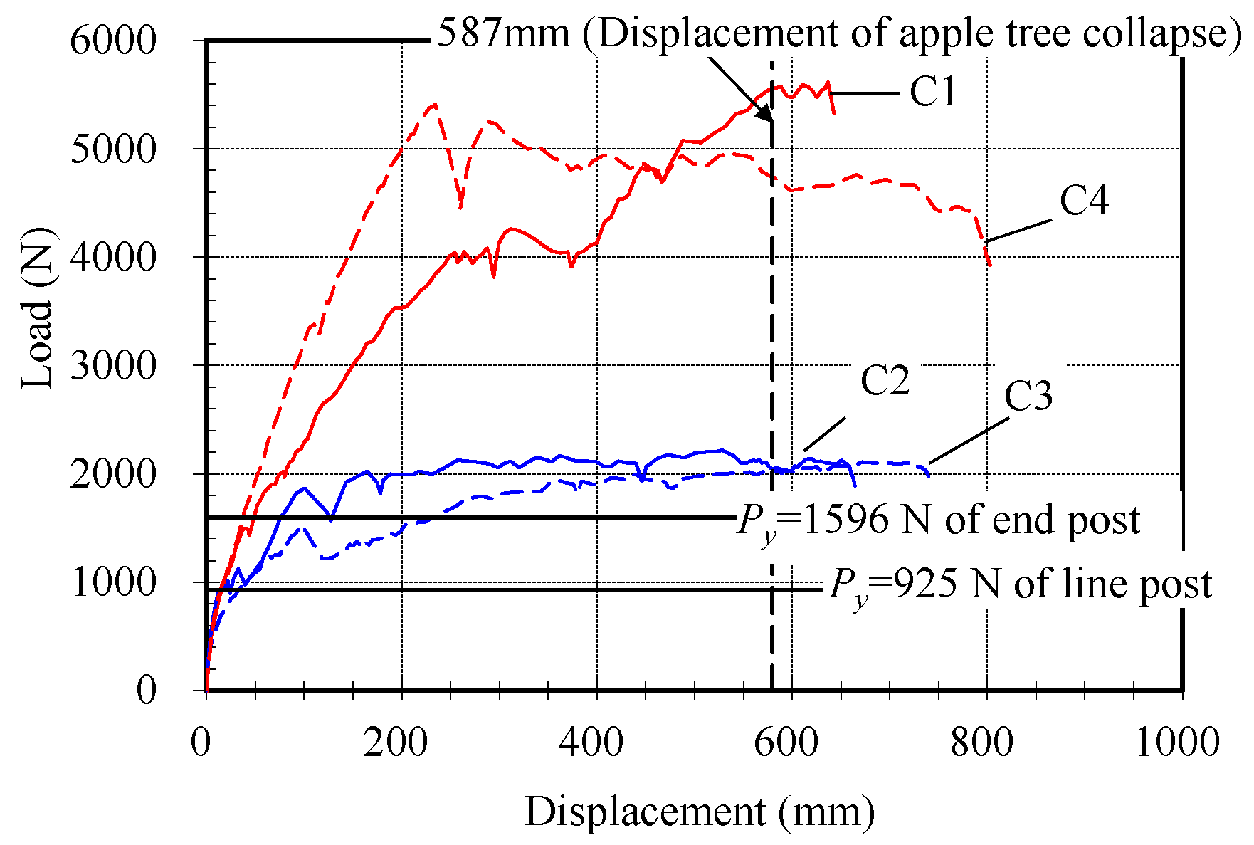
Figure 16 and Figure 17 show the load–displacement relationship of the two tests of the matrix support system. The line post and end post manifested loads greater than the yield load during the test. In particular, the end post exhibited a load three times greater than the yield load, owing to the influence of the strut wire and matrix horizontal wire (mat wire).
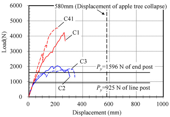
Figure 16.
Test result of matrix support 1.
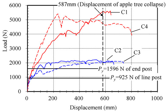
Figure 17.
Test result of matrix support 2.
4. Design of the Anti-Disaster Support System
4.1. Design Method
Orchard systems have been developed to increase productivity, not for the safety of the trees. Hester and Cacho [13] suggested a dynamic simulation model based on the complex biological and economic relationships in an apple orchard system. In this paper, an orchard system for the safety of trees from disasters was designed. The design of an anti-disaster support system for apple trees follows the allowable stress design method [14]. The design method is based on elasticity analysis to apply a safety rate in consideration of various variables such as the applied load or uncertainty of the materials. The anti-disaster support system for apple trees was designed so that the resistance moment of the apple tree and support pipe would be greater than the required moment generated by wind load. When the safety rate of allowable stress design is set to 1.67, the design can be expressed as Equation (1):
where Mf is the required moment due to wind load; Ma is the resisting moment of the apple tree; My is the yield moment of the support pipe; Ω is the safety rate (equal to 1.67); and 1/Ω is the reduction coefficient (equal to 0.6).
4.1.1. Wind load
The variables to calculate the wind load (Wf) are generally considered to be velocity pressure (qh), gust coefficient of influence (Gf), drag coefficient (Cd), and effective net area (An), as shown in Equation (2). However, there is a limitation on directly applying the computational formula to calculate the wind load on the apple trees. Therefore, the wind speed (V10), which was measured at 10 m height, was used as an instantaneous wind speed of 3 s in the 30 year reproduction period. The gust coefficient of influence represents a dynamic behavior component generated due to wind turbulence and a value statistically representing the ratio of maximum displacement to average displacement. In general, it is greater than 1.0; however, in this study, 1.0 was used because the instantaneous wind speed was applied.
The drag coefficient is a value determined by the shape of the elevation where the wind acts. The elevation of an apple tree is not standard, so it is required to obtain the drag coefficient through an experiment. Shin et al. [15] performed a wind tunnel test to measure the actual wind load on the apple trees, and the drag coefficient was suggested as Equation (3). In addition, the wind pressure can be increased by the dynamic effect of wind permeation, and Wilson [16] presented the drag coefficient according to 20~50% porosity and expressed the numerical value. Ferreira [17] constructed a poplar tree with a porosity of 87% at trunk level and 60% at the crown and measured the speed of the wind appearing on the backside. It was shown that wind speed appeared up to 1.6 times in the outskirts, but the average was 1.0. Therefore, the effect of porosity can cause an increase in wind speed, but it is not included in the calculation of the wind load acting on the apple trees.
where Vh is the wind speed at the average height of the apple tree.
In an axiom of uniform stress [18], the trees have growth in response to the loads such as wind and snow load at a specific part, which would consume energy and nutrients by growing necessary wood. The shape of the tree based on the axiom of uniform stress could be considered the same under the action of a non-directional wind load. The effective net area is a value considering a leaf area from the gross area of the tree. Wei et al. [19] investigated the individual tree leaf area density and leaf area index measurement methods using terrestrial laser scanning. Gongal et al. [20] suggested the accurate crop load estimation using a machine vision system based on an image-processing procedure. The effective net area was calculated as 75 percent of the gross area of the apple tree [15]. Table 3 presents the wind load acting on the apple tree based on the wind speed and Equation (2):
Table 3.
Wind load acting on an apple tree.
4.1.2. Required Moment
Nonetheless, because wind load cannot be directly exerted on the apple trees, an equivalent static test, mentioned in Section 3, was carried out in this study. Although the wind load acting on the apple tree may vary depending on the wind direction, the wind load at the front, which is the highest load acting on the tree, was considered. The wind load to the support pipe is simulated through trellis wire. Figure 18 and Equation (4) are presented based on the assumption that the wind load is directly proportional to the load applied to the trellis wire with respect to the area of apple trees.

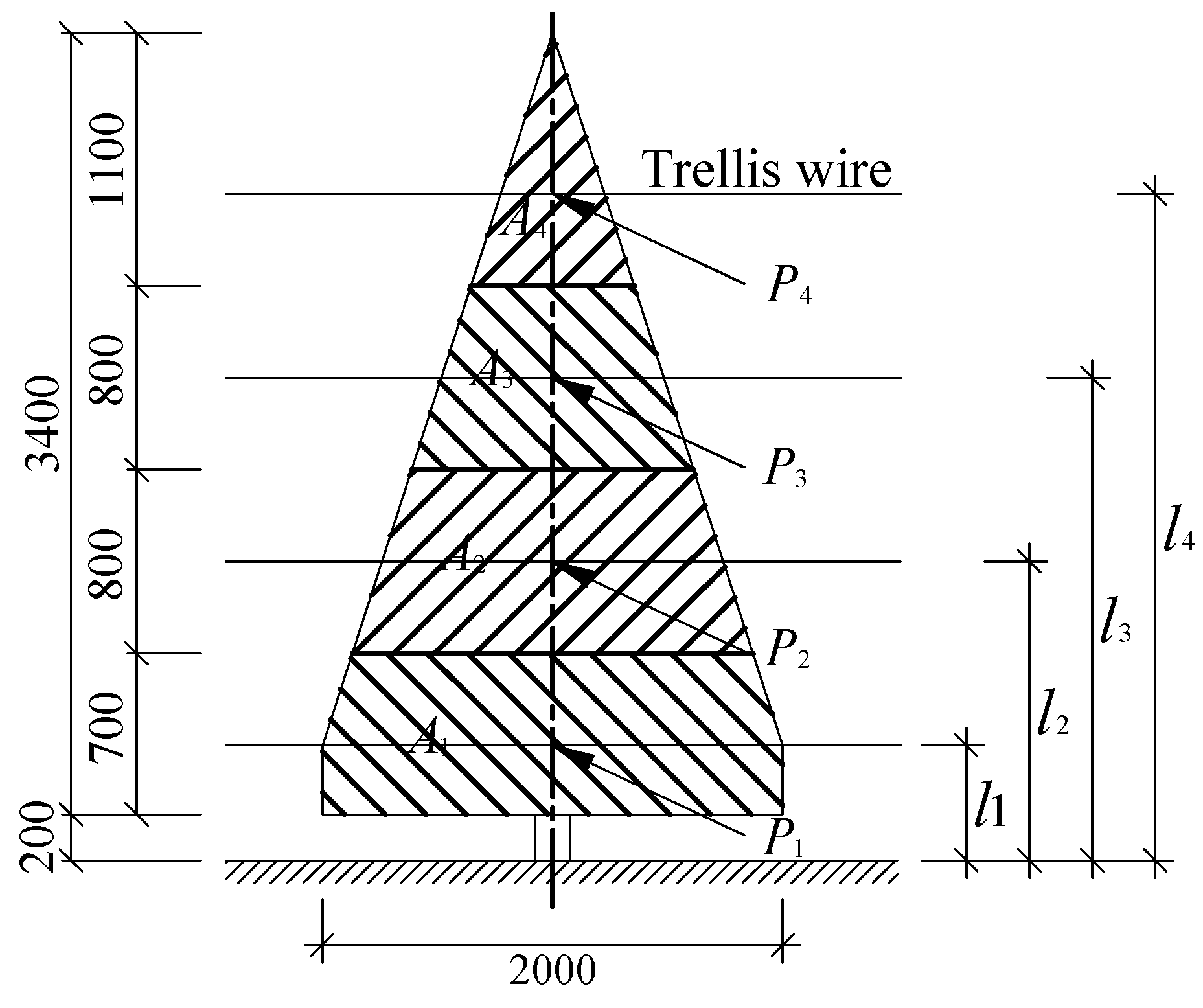 Here, Ag is the gross area of one apple tree; A1~A4 is the area applied to the trellis wire; l1~l4 is the height from the ground to the trellis wire; P1~P4 is the wind load applied to the trellis wire (Wf = P1 + P2 + P3 + P4); and le is the effective height of the overall wind load.
Figure 18.
Estimation of the area required for moment transformation.
Figure 18.
Estimation of the area required for moment transformation.
4.1.3. Design Moment of Steel Pipe
The resisting moment of one apple tree (Ma) was computed to be 202 N·m via the collapse test [11]. The yield moment of all of the support pipes was computed by Equation (4). In the design of the fence support, the first linear load, due to the lack of bearing capacity of the soil, was considered for the line post. For the case of the end post, a moment reduction coefficient of 0.6 was multiplied to compute the yield moment of each support pipe in consideration of the load with respect to the displacement of the apple tree collapse. The moment reduction coefficient was set back to 1.0 for the design of the matrix support, so that the yield moment of each support pipe was used as it was, without any reduction.
Here, a is the moment reduction coefficient (equal to be 0.6); Mye is the yield moment of the end post; and Myi is the yield moment of the line post.
4.2. Safety Review
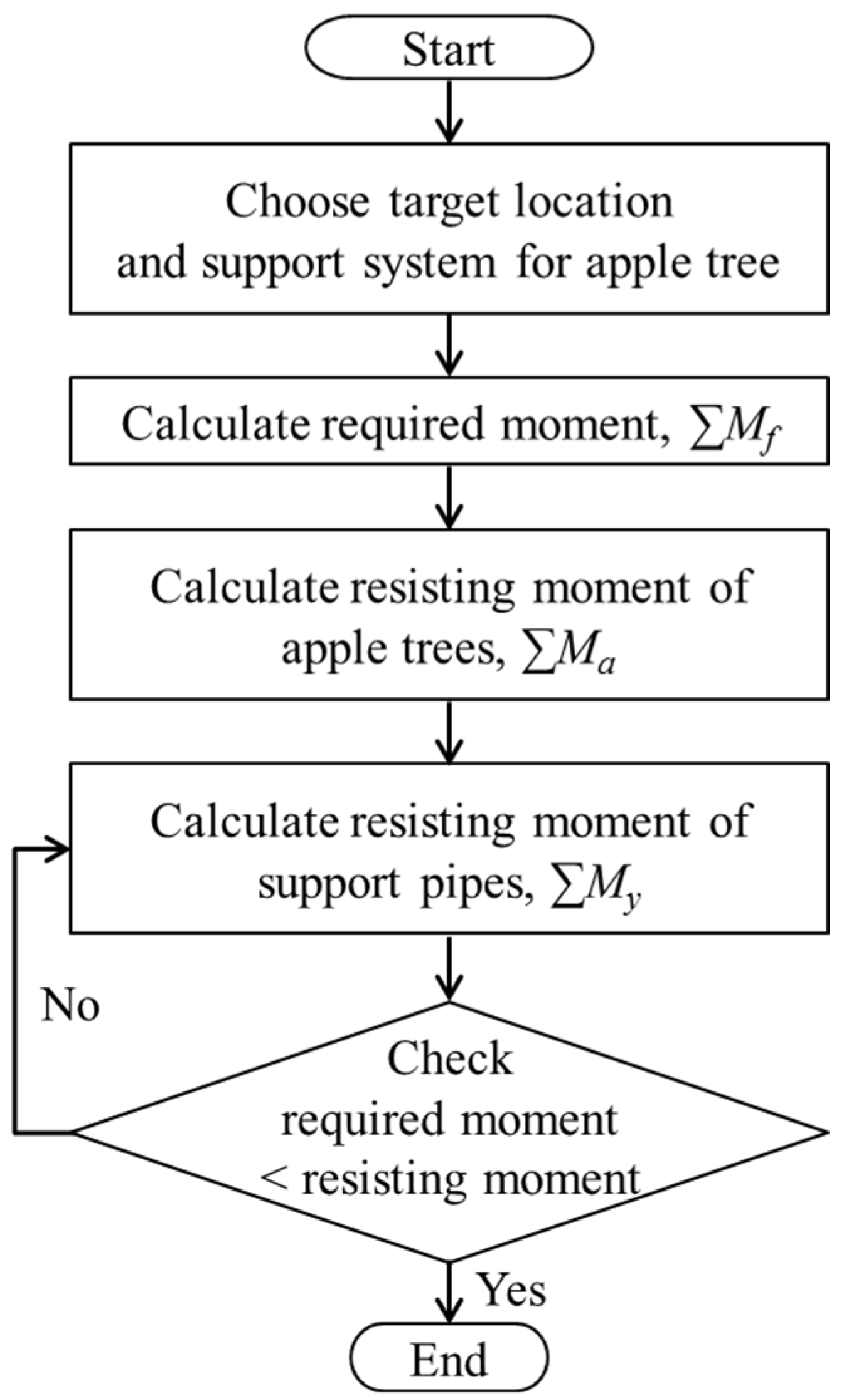
The safety of the apple tree support was examined by comparing the yield moment of the support pipe, the resistance moment of the apple tree, and the required moment due to the wind load, as shown in Equation (1). Figure 19 is the flowchart showing the safety review procedure of the support pipe for apple trees. An example of the safety review for the fence support system is presented in Appendix A. An anti-disaster fence support for apple trees can be designed in accordance with the flowchart. If the support is found to be unsafe, the support pipe can be reselected according to pipe size in standard [11] to have the safety of the new support system re-examined. The wind velocity by locality is to be selected pursuant to the design standard [21].
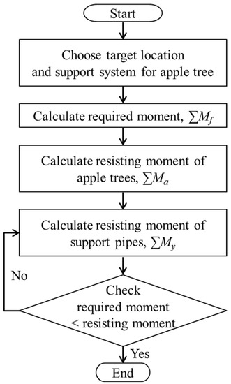
Figure 19.
Flowchart for safety review of the support system design.
Figure 20 and Figure 21 are mimetic diagrams of the fence and matrix support system. They visually show the modeling of the anti-disaster design of the support system in consideration of the wind velocity by locality, as proposed in this study.
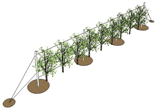
Figure 20.
Mimetic diagram of fence support.
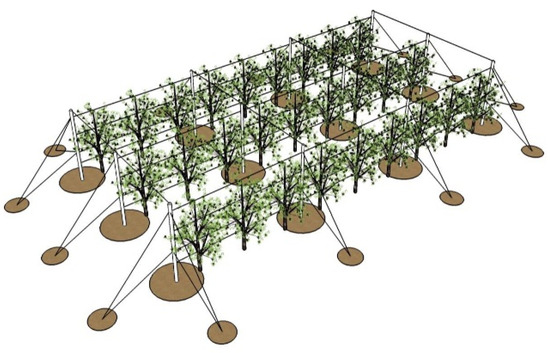
Figure 21.
Mimetic diagram of matrix support.
Using the allowable stress design method, Table 4 and Table 5 show the standard specifications for the apple tree support system in consideration of wind velocity by locality after selecting the members pursuant to the specification of KS D 3760 [11]. According to Table 4, the fence support and matrix support in the case of the circular hollow section (CHS) steel pipe can withstand wind velocities of up to 30 m/s and 38 m/s, respectively. It was reasoned that the support system was limited by wind velocity due to the sectional property of the CHS steel pipe. Therefore, the standard specification of the apple tree support system was proposed anew according to Table 4 by selecting a rectangular hollow section steel pipe as a member of the support system. Additionally, the strut wire, trellis wire, and mat wire of the matrix support system were specified, as well as the specification of turnbuckle to bring about tension on the wire. Although the trellis wire was designed to be ø2.38, as shown in Figure 5, its specification should be determined on the basis of the structural design principle. The factors of influence on the tension of the wire are the initial tension during its installation and the wind load to the apple tree. The additional tension due to wind load is considered to be the main factor of influence. The maximum tension of the trellis wire was the tension as measured at the point of the collapse angle of the apple tree (10.4°).
Table 4.
Specification of the support system according to wind speed (CHS pipe).
Table 5.
Specification of the support system according to wind speed (RHS pipe).
5. Conclusions
A stub column test of the support pipe for an apple tree and an equivalent static test of the apple tree support system were carried out to design a wind-resistant support system for apple trees. The following conclusions are derived from the test result based on the allowable stress design method.
(1) Preliminary study indicated that an apple tree typically collapsed at an angle of 10.4° on average. This finding was used to compute the displacement at the collapse of the fence support system and matrix support system.
(2) The result of the equivalent static test of the support system for apple trees showed that the connection between the strut wire and mat wire of the matrix support system was very important for the support performance, while the initial bearing capacity of soil was important for the case of the fence support system.
(3) The matrix support system exhibited a performance greater than the yield load of the support pipe. In particular, the end post manifested a performance three times greater than the yield load, owing to the influence of the mat wire.
(4) Using the allowable stress design method in consideration of the wind velocity by locality of the support system for apple trees, a structurally safe design proposal for an anti-disaster support system and a standard specification of the members of the support system were suggested.
It is expected that the proposed specification of the anti-disaster support system can contribute to damage reduction and the prevention of farmers’ economic loss due to severe weather anomalies.
Author Contributions
Conceptualization, H.-D.L., S.-H.L. and J.-S.L.; data curation, H.-D.L. and J.-S.L.; formal analysis, H.-D.L. and J.-S.L.; investigation, J.-S.L. and S.-H.L.; methodology, H.-D.L. and J.-S.L.; project administration, K.-J.S.; resources, H.-D.L., S.-H.L. and J.-S.L.; supervision, K.-J.S. and S.-H.L.; validation, K.-J.S. and H.-D.L.; visualization, J.-S.L. and S.-H.L.; writing—original draft, H.-D.L. and J.-S.L.; writing—review and editing, K.-J.S. and S.-H.L. All authors have read and agreed to the published version of the manuscript.
Funding
This research was supported by a grant (17CTAP-C129825) from Technology Advancement Research Program (TARP) funded by the Ministry of Land, Infrastructure and Transport of the Korean government.
Data Availability Statement
The data presented in this study are available upon request from the corresponding author.
Conflicts of Interest
The authors declare no conflict of interest.
Appendix A
- Choosing the target location and support system for the apple tree:
The support system was chosen as the fence type, as shown in Figure A1, and located at 26 m/s wind velocity.
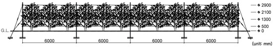
Figure A1.
Fence-type support system (three apple trees supported by one steel pipe).
Figure A1.
Fence-type support system (three apple trees supported by one steel pipe).

- Calculating the required moment (ΣMf):
The wind load acting on one apple tree was 271.7 N (see Table 3), and the effective height of the overall wind load was 1.34 m based on Equation (A1) and Table A1. The moment applied to one apple tree according to the wind load was calculated as 364.1 N·m, and the total required moment was 4369.2 N·m based on twelve apple trees.
Table A1.
The effective height of an apple tree (unit of area is m2 and length is m).
Table A1.
The effective height of an apple tree (unit of area is m2 and length is m).
| A1 | l1 | A2 | l2 | A3 | l3 | A4 | l4 | Ag | le |
|---|---|---|---|---|---|---|---|---|---|
| 1.32 | 0.50 | 1.15 | 1.30 | 0.75 | 2.10 | 0.38 | 2.90 | 3.60 | 1.34 |
- Calculating the resisting moment of apple trees (ΣMa):
The resisting moment of one apple tree (Ma) was measured to be 202.0 N·m, and the total resisting moment was 2424.2 N·m based on twelve apple trees.
- Calculating the resisting moment of support pipes (ΣMy):
The resisting moment of the support pipes was calculated by Equation (4), and this fence-type support system had two external (end post) and three internal (line post) pipes. According to Table 4, the external and internal steel pipes were assumed to be ø59.9 × 2.3 and ø48.1 × 2.3, respectively. The total resisting moment of the support pipes was 3964.2 N·m, as shown in Equation (A2).
- Checking the safety of support pipes:
Based on the ASD method, the total resisting moment was greater than the total required moment of the apple trees and support, as shown in Equation (A3). Therefore, the fence support system was safe at 26 m/s velocity.
References
- MAFRA. Development of Support Systems for High-Density Apple Orchards, Ministry of Agriculture. In Food and Rural Affairs; Ministry of Agriculture: Sejong City, Republic of Korea, 2000. [Google Scholar]
- Kim, S.; Kim, Y.; Kim, M.; Choi, Y.; Shin, K. Investigation of apple tree plane area to design wind load of support system. In Proceeding of the Korean Society for Agricultural Machinery, Jeonju, Republic of Korea, 29 October 2015. [Google Scholar]
- Shin, K.J.; Lee, Y.J.; Park, S.; Kwon, H.; Kim, S.H. Numerical analysis of fence type support for apple trees. In Proceedings of the Korean Society for Agricultural Machinery, Jeonju, Republic of Korea, 27 April 2014. [Google Scholar]
- Kim, S.; Kim, Y.; Kim, M.; Choi, Y.; Shin, K. Experimental analysis on binding strength of support pipe clamp for apple tree support system. In Proceedings of the Korean Society for Agricultural Machinery, Cheonan, Republic of Korea, 30 October 2014. [Google Scholar]
- Robinson, T.; Hoying, S.; Sazo, M.M.; DeMarree, A.; Dominguez, L. A Vision for Apple Orchard Systems of the Future. N. Y. Fruit Q. 2013, 16, 13–16. [Google Scholar]
- Middleton, S.; McWaters, A.; James, P.; Jotic, P.; Sutton, J.; Campbell, J. The Productivity and Performance of Apple Orchard Systems in Australia. Compact. Fruit Tree 2002, 35, 43–47. [Google Scholar]
- Lespinasse, J.M.; Delort, J.F. Apple tree management in vertical axis: Appraisal after ten years of experiments. Acta Hortic. 1986, 160, 139–156. [Google Scholar] [CrossRef]
- Palmer, J.W.; Avery, D.J.; Wertheim, S.J. Effect of Apple Tree Spacing and Summer Pruning on Leaf Area Distribution and Light Interception. Sci. Hortic. 1992, 52, 303–312. [Google Scholar] [CrossRef]
- Robinson, T. The Evolution towards More Competitive Apple Orchard Systems in the USA. In XXVII International Horticultural Congress-IHC2006: International Symposium on Enhancing Economic and Environmental 772; ISHS: New York, NY, USA, 2008. [Google Scholar]
- Cooperative Extension: Tree Fruits. Available online: https://extension.umaine.edu/fruit/growing-fruit-trees-in-maine/spacing/ (accessed on 19 August 2023).
- KSA. Coated Steel Pipes for Plastic Housing (KS D 3760); Korean Standards Association (KSA): Seoul, Republic of Korea, 2014. [Google Scholar]
- Lee, Y.-J.; Kim, S.-H.; Kim, H.-J.; Shin, K.-J. Numerical Analysis of the Fence-Type Support for Apple Tree using Steel Pipe. J. Archit. Inst. Korea 2015, 17, 203–210. [Google Scholar]
- Hester, S.M.; Cacho, O. Modelling apple orchard systems. AGR SYST 2003, 77, 137–154. [Google Scholar] [CrossRef]
- AISC. AISC 360-22 Specification for Structural Steel Buildings; American Institute of Steel Construction: Chicago, IL, USA, 2022. [Google Scholar]
- Shin, S.-H.; Shin, K.-J.; Kim, S.-H.; Kim, H.-J. Drag Coefficient for Structural Design of Orchard Supporting System by Wind Tunnel Measurement. J. Wind. Eng. Inst. Korea 2015, 19, 147–154. [Google Scholar]
- Wilson, J.D. Numerical studies of flow through a windbreak. J. Wind. Eng. Ind. Aerodyn. 1985, 21, 119–154. [Google Scholar] [CrossRef]
- Ferreira, A.D. Structural design of a natural windbreak using computational and experimental modeling. Env. Fluid Mech. 2011, 11, 517–530. [Google Scholar] [CrossRef]
- Mattheck, C.; Breloer, H. The Body Language of Trees; HMSO: London, UK, 1994.
- Wei, S.; Yin, T.; Dissegna, M.A.; Whittle, A.J.; Ow, G.L.F.; Yusof, M.L.M.; Lauret, N.; Gastellu-Etchegorry, J.-P. An assessment study of three indirect methods for estimating leaf area density and leaf area index of individual trees. Agric. For. Meteorol. 2020, 292, 108101. [Google Scholar] [CrossRef]
- Gongal, A.; Silwal, A.; Amatry, S.; Karkee, M.; Zhang, Q.; Lewis, K. Apple crop-load estimation with over-the-row machine vision system. Comput. Electron. Agr. 2016, 120, 26–35. [Google Scholar] [CrossRef]
- RDA. Blueprint·Specification for the Anti-Disaster Standard of Special Horticultural Facility; Rural Development Administration: Jeonju-si, Republic of Korea, 2014. [Google Scholar]


Disclaimer/Publisher’s Note: The statements, opinions and data contained in all publications are solely those of the individual author(s) and contributor(s) and not of MDPI and/or the editor(s). MDPI and/or the editor(s) disclaim responsibility for any injury to people or property resulting from any ideas, methods, instructions or products referred to in the content. |
© 2023 by the authors. Licensee MDPI, Basel, Switzerland. This article is an open access article distributed under the terms and conditions of the Creative Commons Attribution (CC BY) license (https://creativecommons.org/licenses/by/4.0/).