Article

Performance Comparison of Traction Synchronous Motors with Ferrite Magnets for a Subway Train: Reluctance versus Homopolar Variants

by
Vladimir Dmitrievskii
,
Vadim Kazakbaev
and
Vladimir Prakht
*
Department of Electrical Engineering, Ural Federal University, 620002 Yekaterinburg, Russia
*
Author to whom correspondence should be addressed.
Appl. Sci. 2023, 13(17), 9988; https://doi.org/10.3390/app13179988
Submission received: 14 August 2023 / Revised: 31 August 2023 / Accepted: 2 September 2023 / Published: 4 September 2023
(This article belongs to the Topic Advanced Electrical Machines and Drives Technologies)

Abstract

:
Due to the high cost and the predicted shortage of rare earth elements in the near future, the task of developing energy-efficient electric machines without rare earth magnets is of great importance. This article presents a comparative analysis of optimized designs of a ferrite-assisted synchronous reluctance machine (FaSynRM) and a ferrite-assisted synchronous homopolar machine (FaSHM) in a 370-kW subway train drive. The objectives of optimizing these traction machines are to reduce their losses, maximum armature current, and torque ripple. The optimization considers the characteristics of the machines in the subway train moving cycle. The problem of the risk of irreversible demagnetization of ferrites in the FaSynRM and FaSHM is also considered. To reduce the computational burden, the Nelder-Mead method is used for the optimization. It is shown that the FaSHM demonstrates better field weakening capability, which can reduce the maximum current, power, and cost of the inverter power modules. At the same time, the FaSynRM requires less permanent magnet mass for the same torque density and is more resistant to irreversible demagnetization, which can reduce costs and improve the reliability of the electric machine.

1. Introduction

1.1. Disadvantages of Induction Motors and Motors with Rare Earth Magnets

At present, most traction drives, including those of trains, trams, subways, and mining dump trucks, use induction motors (IM). However, traction drives with IMs have the following disadvantages:
(1)
Large loss and heating in the rotor [1,2], which can lead to unacceptably high temperatures of the rotor, shaft, and bearings, even despite the liquid cooling of the rotor [3];
(2)
Continuous torque capability is significantly worse than permanent magnet synchronous motors (PMSM) [4];
(3)
Higher inverter power rating with a required constant power speed range (CPSR) over 3:1 [5,6]. For example, a study [5] presents a traction drive based on an IM with a mechanical power of 50 kW and a CPSR of 3.5:1, and the power rating of the traction inverter is 125 kVA. Study [6] presents a traction drive based on an IM with a mechanical power of 50 kW and a CPSR of 4:1, and the power rating of the traction inverter is 125 kVA.
To overcome these disadvantages, rare earth permanent magnet synchronous motors (PMSM) are used, which have a larger specific torque, lower loss, and a higher power factor [7]. However, PMSMs have the following disadvantages:
(1)
The production of PMSMs necessitates costly rare-earth magnets, which experience significant price fluctuations within a short span of a year or two. This variability arises due to a limited pool of magnet suppliers in the global market [8,9,10];
(2)
In the near future, a shortage of materials for the production of rare earth magnets is predicted due to the rapid growth in the production of electric vehicles and wind turbines, which very often use rare earth permanent magnets [11];
(3)
Rare-earth element extraction has an adverse environmental impact [12];
(4)
The demagnetization of rare-earth magnets can occur in high-power density PMSMs due to the presence of strong magnetic fields and high temperatures;
(5)
The task of maintaining high efficiency at speeds near the maximum becomes challenging when aiming for a wide constant power speed range, primarily due to increased copper loss that occurs in the field weakening mode [13];
(6)
Furthermore, in electrical power applications such as subway and railway trains, the rotational motion of PMSM induces a significant uncontrolled electromotive force (EMF) in the winding. This situation presents a significant risk of fire in the event of an emergency short circuit. Given the high inertia of the trains, which makes them unable to stop in time in such critical situations, it is recommended to refrain from using the PMSM in this application.
Due to the disadvantages of IM and PMSM, the development of synchronous motors for the subway without rare earth magnets becomes relevant.
The utilization of ferrite magnets proves advantageous due to their significantly lower cost compared to rare-earth magnets and their widespread production across numerous countries worldwide [14,15].
In addition, ferrite magnets have no losses due to eddy currents and high-temperature strength [14,16]. A challenge of using ferrites in motor design is their low coercive force [14,17]. For this reason, when optimizing motors with ferrite magnets, special attention must be paid to limiting irreversible demagnetization.

1.2. Literature Overview on the Use of Ferrite-Assisted Synchronous Reluctance Motors in Traction Drives

Magnet-free synchronous reluctance motors (SynRMs) have lower losses than induction motors. However, in electric vehicles that require a wide CPSR, SynRMs have a reduced inverter utilization factor, which significantly increases the power rating and cost of the inverter power modules [6]. This drawback can be overcome, as well as the dimensions of the motor can be reduced by adding inexpensive ferrite magnets to the rotor [14]. Ferrite-assisted SynRMs (FaSynRMs) with high rotor magnetic anisotropy have proven themselves in pumping applications in which a wide CPSR is not required [18,19,20]. Moreover, FaSynRM is also an alternative to IPMSM in electric vehicle applications, with comparable torque capability, lower permanent magnet cost, and better field-weakening capability [21,22].
For example, in [21], the characteristics of PMSM and FaSynRM are theoretically compared in a Toyota Prius 2010 drive with a rated power of 60 kW and CPSR of 3.5:1. It is concluded that the FaSynRM has characteristics similar to the original V-shaped interior PMSM with the same overall dimensions, while the cost of its active materials is much lower, and the maximum operating temperature of the rotor is much higher. In [22], a theoretical comparison is made between V-shape rare-earth assisted SynRM and FaSynRM for a BMW i3 2016 drive with a rated power of 60 kW and CPSR of 3:1. It is shown that the use of ferrite magnets makes it possible to obtain lower peak mechanical stress, better field-weakening capability, higher peak efficiency, and comparable efficiency over the operating range.
It can be concluded that quite a lot of articles are devoted to the analysis of FaSynRM characteristics in light passenger vehicles. However, studies on optimizing FaSynRM design for a subway train drive have not been presented.

1.3. Literature Overview on the Use of Synchronous Homopolar Motors in Traction Drives and on the Use of Ferrite-Assisted Synchronous Homopolar Motors

Another alternative to PMSMs in electric vehicles is electrically excited wound rotor synchronous motors (WRSM), which solve many of the problems associated with rare earth magnets but require a solution to the problem of unreliable sliding contact [23].
By merging the advantages of permanent magnet synchronous machines (PMSMs) and wound rotor synchronous machines (WRSMs), synchronous homopolar machines (SHMs) eliminate the need for slip rings like in PMSMs and, similar to WRSMs, operate without magnets. They achieve a wide constant power speed range (CPSR) due to their adjustable excitation current. One advantage SHMs have over WRSMs is that the number of excitation coils is independent of the number of poles, whereas, in WRSMs, it increases with the number of poles, resulting in reduced excitation magnetomotive force (MMF) [14]. As a result, SHMs have lower mass and reduced losses in the excitation winding compared to WRSMs. Additionally, since SHMs have no losses in the rotor, there is no need for rotor cooling. SHMs find applications as highly reliable generators in various fields, including laser technology, pulse heating, welding units [24], automotive generators [25], railway passenger cars, ships, and aircraft [26].
In addition, the application of SHM in traction drives is being studied.
In [23,27], the utilization of SHMs as traction motors in mining trucks is discussed. Paper [27] presents and validates the computation method for the traction SHM, which relies on a set of 2D magnetostatic boundary problems. Furthermore, SHM optimization techniques for traction applications were developed [23] using the Nelder-Mead algorithm and the model proposed in [27]. Also, the performance of SHMs was compared with other types of motors. For example, in contrast to WRSMs, traction SHMs exhibit certain drawbacks, as highlighted in reference [27]. Firstly, the mass and dimensions of SHMs exceed those of WRSMs due to each rotor tooth covering roughly one pole pitch, leaving approximately half of the pole pitches unused for torque production. Secondly, SHMs necessitate a higher inverter power rating compared to WRSMs.
Several studies [28,29,30,31] have explored multi-pole SHMs that feature an excitation winding on the stator and rare-earth magnets housed in the rotor slots. These SHMs, equipped with rare-earth magnets, offer advantages over those without permanent magnets. The use of rare-earth magnets enhances the utilization of the rotor surface, while keeping the weight and dimensions comparable to conventional PMSMs. In traction drives with a wide constant power speed range (CPSR), SHMs with rare-earth magnets excel by exhibiting higher inverter utilization and lower costs for the inverter. The excitation winding enables the adjustment of the excitation flux across a wide range of speeds, utilizing the excitation winding current as an additional control signal to enhance SHM performance optimization. However, a notable drawback of SHMs with rare-earth magnets lies in their dependency on a limited number of rare-earth element suppliers, leading to high material costs. Moreover, the depth of the rotor slots in these SHMs is significantly smaller compared to those without magnets, compromising the saliency of the rotor. Consequently, although rare-earth magnets provide substantial additional torque, the primary torque generated by the interaction between the field of the excitation winding, modulated by rotor stacks, and the field of the stator winding is diminished.
To enhance the characteristics of SHMs with magnets, an alternative approach involves utilizing cost-effective ferrite magnets in their construction. Ferrite magnets are considerably less expensive than rare-earth magnets and are produced in numerous countries worldwide [10]. The application of ferrite magnets in SHMs is exemplified in [26], where they are employed as under-car generators for railway passenger cars. The use of SHM with ferrite magnets, compared with those without magnets, offers such advantages as reducing the weight and dimensions of the machine, as well as minimizing power losses.
Research on synchronous homopolar motors featuring ferrite magnets (for brevity in this paper, we call them ferrite-assisted synchronous homopolar motors, FaSHMs) is relatively infrequent. For example, in [14], the characteristics of a FaSHM are compared with the characteristics of an SMH without magnets in the drive of a subway train bogie.

1.4. The Problem and Aim of the Study

An overview of the literature shows that although there are studies of the characteristics of FaSynRM and FaSHM in traction drives, a comparative analysis of the characteristics of these types of motors in the drive of a subway train bogie is not presented. In this paper, the characteristics of the FaSynRM and the FaSHM for a 370 kW subway train bogie drive are optimized, and their comparative analysis is provided. The optimization of the motor designs is carried out using the computationally efficient Nelder-Mead method, which makes it possible to consider the driving cycle of the train and not just the rated operating point. Optimization considers several criteria, such as cycle losses, maximum inverter current, torque ripple, and the degree of irreversible demagnetization of the permanent magnets.
We would like to highlight that although the optimization of the FaSHM for the subway drive was already considered by the authors in [14]. However, the losses in the section of the train running due to inertia (see Figure 1, “Coasting” section) that occur in the magnetic core, which are significant due to the long duration of this section of the cycle, were not taken into account. Therefore, when compared to the FaSynRM, this study re-optimized the FaSHM design to take this factor into account.

2. Representation of the Train Flow Pattern in the Motor Optimization Routine

The movement of the subway train, as depicted in Figure 1, encompasses several stages: acceleration with a constant torque, acceleration with a constant power, coasting at a steady speed (with any minimal deceleration disregarded), deceleration with a constant power, and deceleration with a constant torque. The maximum torque remains constant at T0 = 1240 N∙m for both motor and generator modes. The speed of transitioning between constant power and constant speed modes is nm = 1427 rpm during acceleration and ng = 2854 rpm during braking. The maximum attainable speed is nmax = 4280 rpm.
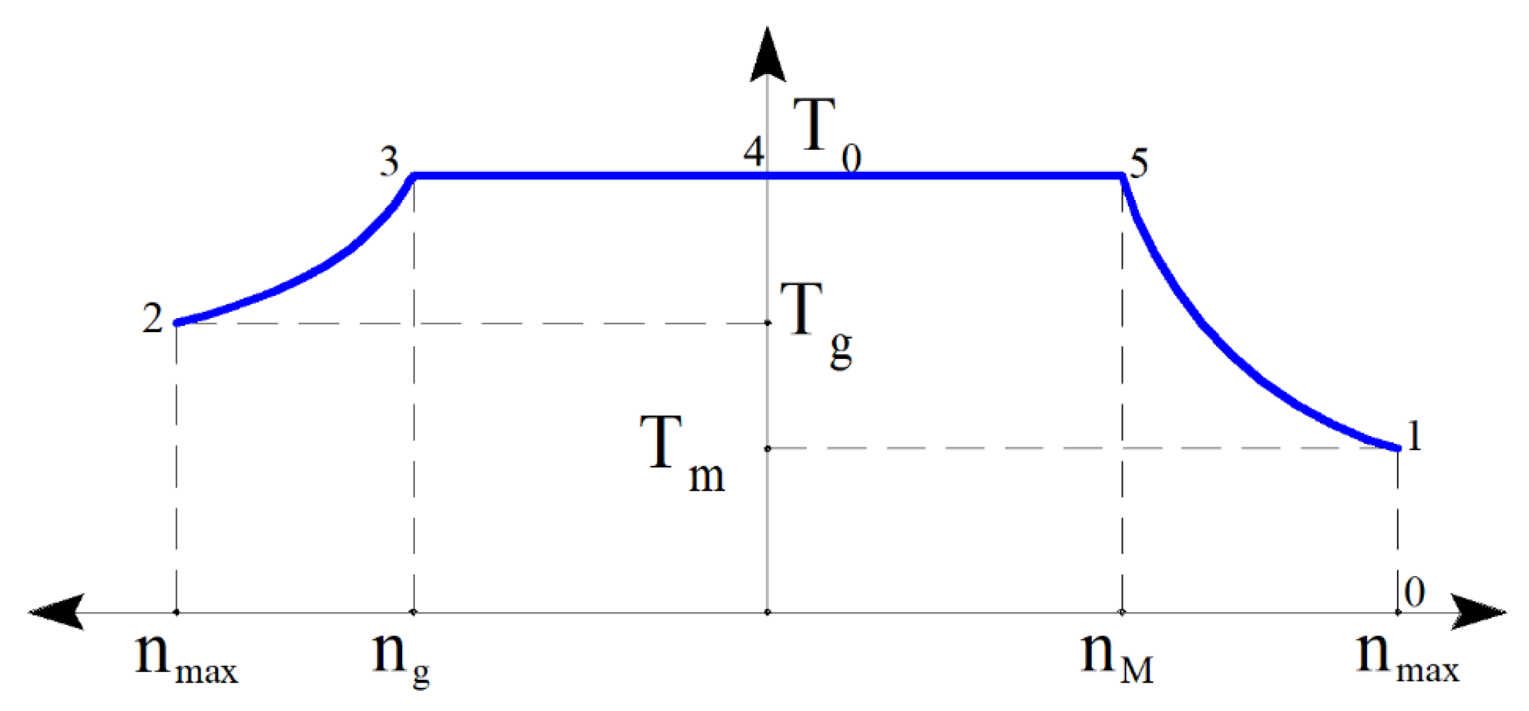
Figure 2 illustrates the torque dependency on rotational speed, with two separate abscissa axes representing the motor and generator modes. The optimization routine of the FaSHM for specific operating points 1, 2, 3, 4, and 5 depicted in Figure 2 is detailed in [14]. This optimization process encompasses all stages of the operating cycle, excluding coasting. The optimization function incorporates objectives such as weighted average electric losses evaluated over the cycle, with the weight coefficients wi determined using the trapezoid quadrature formula. Building upon this research, the present study further refines the optimization procedure for traction motors with magnets in subway trains, considering the core losses during coasting mode. Despite the motor being switched off, magnetic fluxes induced by the magnets still result in coasting-related losses. Therefore, this study also considers the coasting mode (operating point 0). If coasting occupies 50% of the time required for travel between stations, integration of the speed reveals that coasting accounts for 63.3% of the total distance. In this case, the weighting coefficients are calculated as:
wex0 = 1/2; wexi = wi/2, i = 1, 2, 3, 4, 5.
The average loss is calculated as:
<Ploss> = ∑(wexiPloss i),
where Ploss i is the total loss at the i-th operating point.
In each operating point, denoted as Vi, the maximum allowable line-to-line voltage is approximately equal to the DC voltage, although not precisely. In the operating points of generator mode, the voltage Vi slightly surpasses the DC voltage due to the switch voltage drop, while in the operating points of the motor mode, it slightly dips below the DC voltage. To quantify this relationship, we introduce the catenary ratio ki, defined as ki = Vi/VDC rated (VDC rated = 750 V). It is assumed that in modes 1, 2, 4, and 5, the DC voltage is equivalent to that in the catenary, resulting in ki being close to 1. The following margin values are selected: k2 = 1.01, k1 = k4 = k5 = 0.97. In operating point 3 (generator mode), k3 can be chosen greater than in motor modes 1, 4, and 5, owing to the battery charge recuperation. For added safety, all the details pertaining to the specific modes are consolidated in Table 1.

3. Designs Features of the FaSHM and FaSynRM

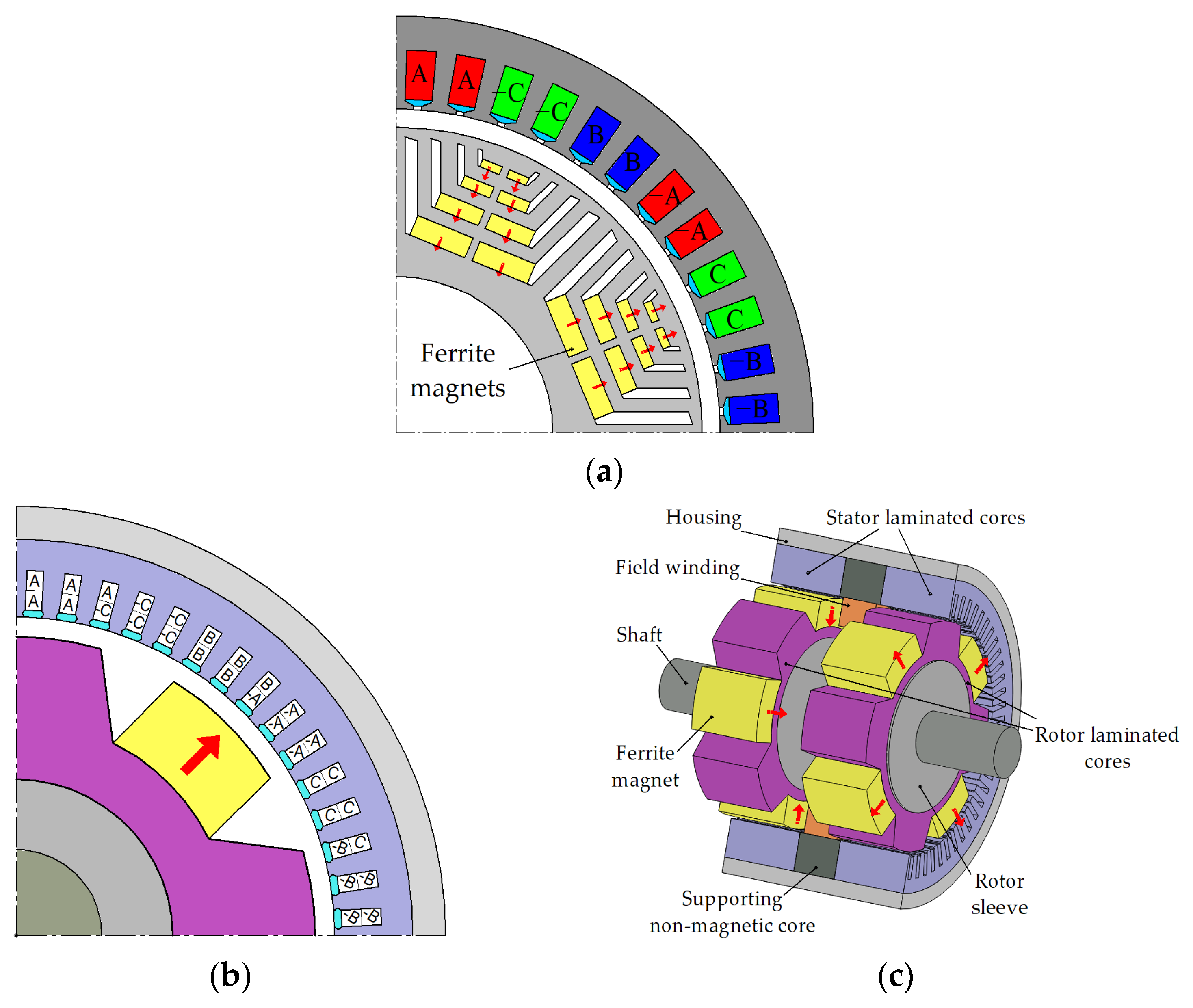
The structure of the FaSynRM magnetic core is uniform along the axis of rotation; therefore, to describe it, it is sufficient to consider only its two-dimensional geometry (Figure 3a). The FaSHM consists of two pairs of stator and rotor stacks connected by axial elements that conduct the excitation magnetic flux. Therefore, to model the FaSHM, it is necessary both to consider the two-dimensional geometry of a pair of stator and rotor packages (Figure 3b) and to consider the design of the axial elements: the stator housing and the rotor sleeve (Figure 3c).
Table 2 shows the main design parameters of the motors. Figure 3 illustrates the motor phases using capital letters A to C to indicate their order. The presence of a minus sign in Figure 3 signifies the reverse direction of the current within a winding layer. Both considered motors have a 3-phase 8-pole winding. The FaSHM stator has 60 slots, and the number of slots per pole and per phase q = 60/(8∙3) = 2.5. The FaSynRM stator has 48 slots, and the number of slots per pole and per phase q = 48/(8∙3) = 2. Unlike the FaSHM, the FaSynRM has only one set of stator and rotor stacks and does not have an excitation winding and its fastening elements, which makes it easier to assemble.
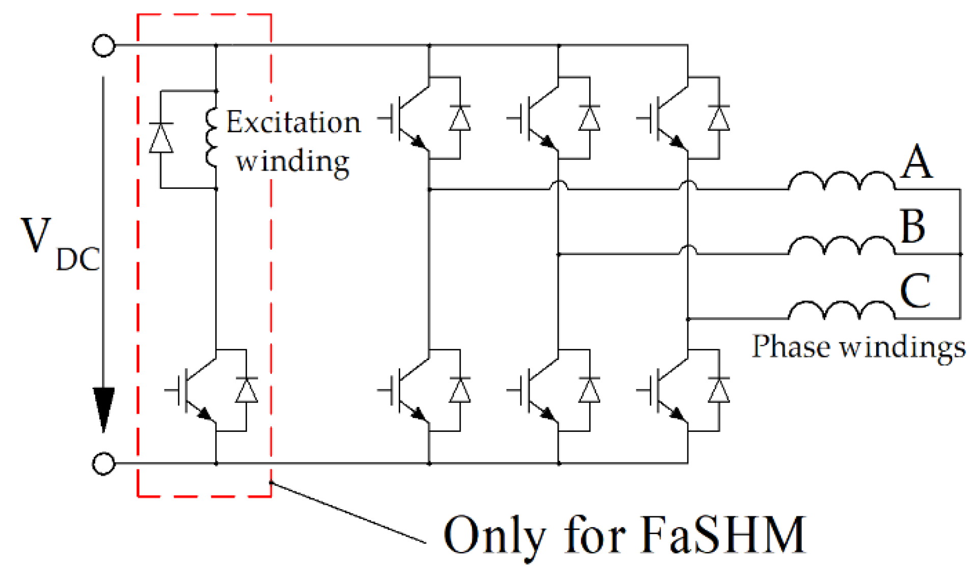
Figure 4 illustrates the power supply circuit for the FaSHM, comprising a standard three-phase inverter for the multiphase armature winding and a chopper for the excitation winding. On the other hand, the FaSynRM solely necessitates a three-phase inverter without the need for a chopper.

4. Objectives and Parameters of the Optimization

Since the external dimensions of the motor are essentially determined by the corresponding dimensions of the car bogie and correspond to the commercial induction motors already used in the drive under consideration, the main emphasis in optimizing the performance is on reducing losses in the duty cycle (see Figure 1) and on reducing the current rating power modules of the traction inverter. When optimizing, it is also necessary to limit torque ripple and prevent irreversible demagnetization of weakly coercive ferrite magnets. Since the applied Nelder-Mead method is an unrestricted method, the constraints are also set by additional terms of the optimization function.
Therefore, the objective function is formulated based on four objectives:
(1)
Minimizing the average electrical losses, denoted as <Ploss el>, which is calculated as a weighted average of losses at different operating points;
(2)
Minimizing the maximum armature winding current, indicated by max(Iarm i), across operating points 1–5;
(3)
Minimizing the maximum torque ripple, indicated by max (TRi), across operating points 1–5;
(4)
Reducing to zero δdemag, which represents the cross-section area of magnets exposed to a demagnetization magnetic field stronger than the marginal demagnetization field H0, relative to the overall cross-section area of the magnets.
When developing an electric motor, it is important to consider the discrete nature of certain parameters, such as the number of turns (Nsec) in the armature winding section and the standardized values of rectangular wire width and height outlined in [32]. However, this study disregards the discreteness of these values and allows them to have any positive real value, aiming to provide a more objective assessment. Random factors arising from different technical specifications in motor development can lead to optimal values of these parameters varying between designs. Specifically, the number of turns in the armature winding (Nsec) is chosen so that VDC rated = max(Vi/ki) [23].
An additional target for FaSHM is the maximum nonsymmetrized torque ripple max(TRnonsymi). This type of torque ripple is generated by a single pair of stator and rotor stacks, whereas a symmetrized torque ripple is produced by the entire FaSHM, involving all pairs of stator and rotor stacks. The details of the terms TR and TRsym are elaborated in [27].
In the FaSynRM, a significant contribution to the torque is generated by the reluctance torque, and the ferrite magnets play an assisting role. Therefore, when properly designed, the FaSynRM is comparatively strong to irreversible demagnetization. To ensure the strength of FaSynRM to such factors as temperature decrease, transients, or failures of the control system with an overcurrent, the maximum value of the demagnetizing field is constrained to H0 = 2 kOe.
In [14], for the FaSHM, the demagnetizing field was not constrained in the objective function, but it was shown that the demagnetizing field does not exceed 3.2 kOe, while the coercive force of ferrite magnets can be 4 kOe. In contrast to [14], in this paper, H0 is constrained for the FaSHM as well since it is under comparison with the FaSynRM, in which irreversible demagnetization is also possible. Moreover, in the FaSHM, the magnets make up for the disadvantage of a magnet-free SHM using only half the poles for torque production [14]. Therefore, in the FaSHM, the magnets are subjected to a greater demagnetizing effect compared to the FaSynRM. Trial runs of the optimization routine with a constraint of H0 = 2 kOe showed an unacceptable reduction in efficiency and an increase in the maximum current of the armature winding. For this reason, a constraint of H0 = 2.5 kOe was adopted for the FaSHM, which is somewhat larger than for the FaSynRM.
Also, in contrast to [14], when optimizing both machines, losses in the coasting mode (see Figure 1) with the motor turned off are considered. Even when the motor is turned off, the losses induced by permanent magnets in the magnetic core are not equal to zero, which is significant due to the long duration of this section of the working cycle.
Hence, the objective function of the FaSHM takes the following form:
F = ln ( < P l o s s > ) + 0.7 ln ( max ( I a r m   i ) ) + 0.025   ln ( max ( T R s y m i ) ) + + 0.01   ln ( max ( T R i ) ) + 150   max ( δ demag ) ,
where <Ploss> is the average total loss calculated in accordance with (2); max(Iarm) is the maximum armature current; max(TRsym) is the maximum value of the symmetrized torque ripple; max(TR) is the maximum value of the nonsymmetrized torque ripple; max(δdemag) is the maximum ratio of the area of permanent magnets with H > H0 to the total area of magnets.
The objective function for the FaSynRM is as follows:
F = ln ( < P l o s s > ) + 0.7   ln ( max ( I a r m   i ) ) + 0.1   ln ( max ( T R i ) ) + 0.1 ln ( M r o t ) + 0.1   ln ( M m a g ) + 150   max ( δ demag ) ,
where Mrot is the mass of the rotor, and Mmag is the mass of the permanent magnets.
The weight constants 150, 1, 0.7, 0.1, 0.025, and 0.01 in Equations (3) and (4) indicate the significance of specific objectives. These values represent the approximate relative priorities assigned to each optimization goal, drawing from the author’s experience in designing comparable machines.
A coefficient of 150 at δdemag ensures the selection of designs in which there is no irreversible demagnetization of permanent magnets. The next most important goal (loss <Ploss>) has a weight coefficient equal to unity.
The constant 0.7 signifies that a 1% decrease in the maximal current holds the same value as a 0.7% reduction in average loss. The objectives of minimizing symmetrized and unsymmetrized torque ripples hold relatively lesser significance. The constants 0.025 and 0.01 indicate that all else being equal, designs with lower torque ripples are favored. Additionally, to enhance clarity, the natural logarithm of Equations (3) and (4) is employed.
The fminsearch optimization procedure according to the Nelder-Mead method [33], implemented in the MATLAB software, is described in detail in [34]. The fminsearch (F, x0) optimization procedure is launched to minimize the value of the objective function F by successively varying the vector x of electric machine parameters, where x0 is the vector of initial values of the electric machine parameters.
The procedure for calculating the objective function F, implemented in MATLAB, includes the steps shown in the flowchart in Figure 5. This flowchart is valid for both FaSHM and FaSynRM. However, for FaSHM, the objective function is calculated according to (3), and for FaSynRM, according to (4). Table 3 shows the list of variable parameters for FaSHM and Table 4 for FaSynRM. After building the geometry of the electric machine corresponding to the current value of the vector x, varied by the fminsearch function, its characteristics are calculated at operating points 0–5 (see Figure 2), necessary to calculate the terms of the objective function.

5. FaSHM Optimization Parameters and Results

5.1. FaSHM Optimization Parameters

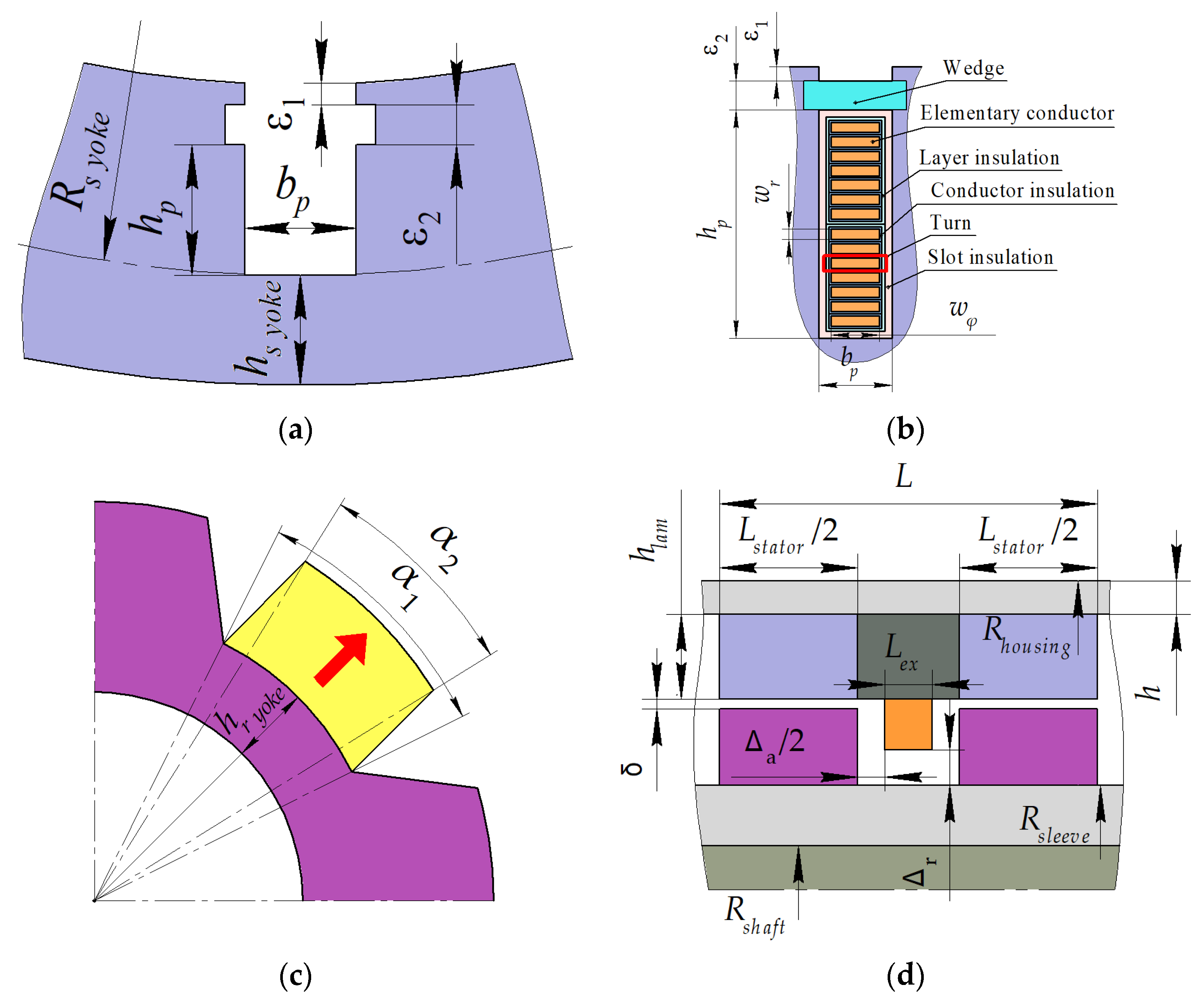
The parameters varied during the optimization of the FaSHM, and fixed ones are shown in Figure 6. Their detailed description and the initial design are given in [14]. Table 5 provides parameters unchanged during the optimization, and Table 3 provides the initial and optimized values of varied ones.

5.2. FaSHM Optimization Results

As Figure 7 shows, the FaSHM optimization process took 180 calls of the objective function, and its value was significantly reduced.
The losses in coasting mode are mainly concentrated in the stator laminated stacks. Its value is 705 W in the design presented in [14] and 639 W in the new design. Other motors’ performance characteristics are presented in Table 6.
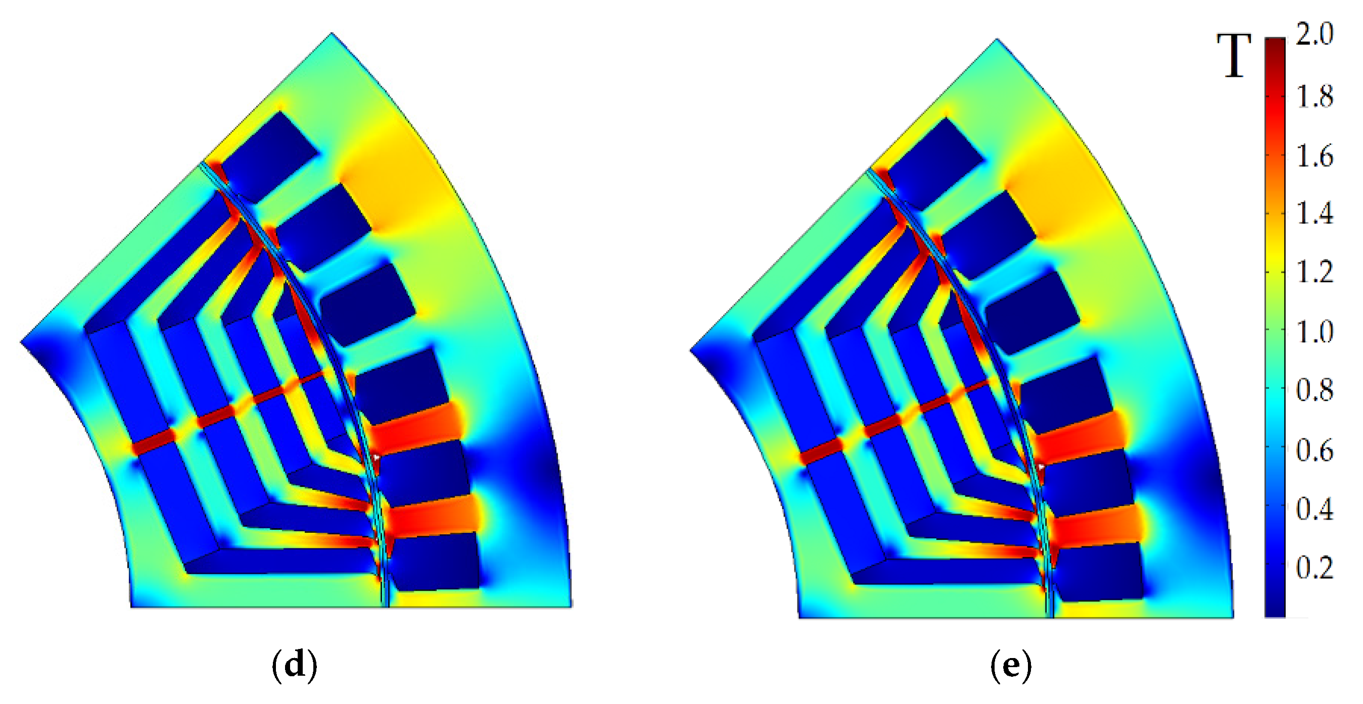
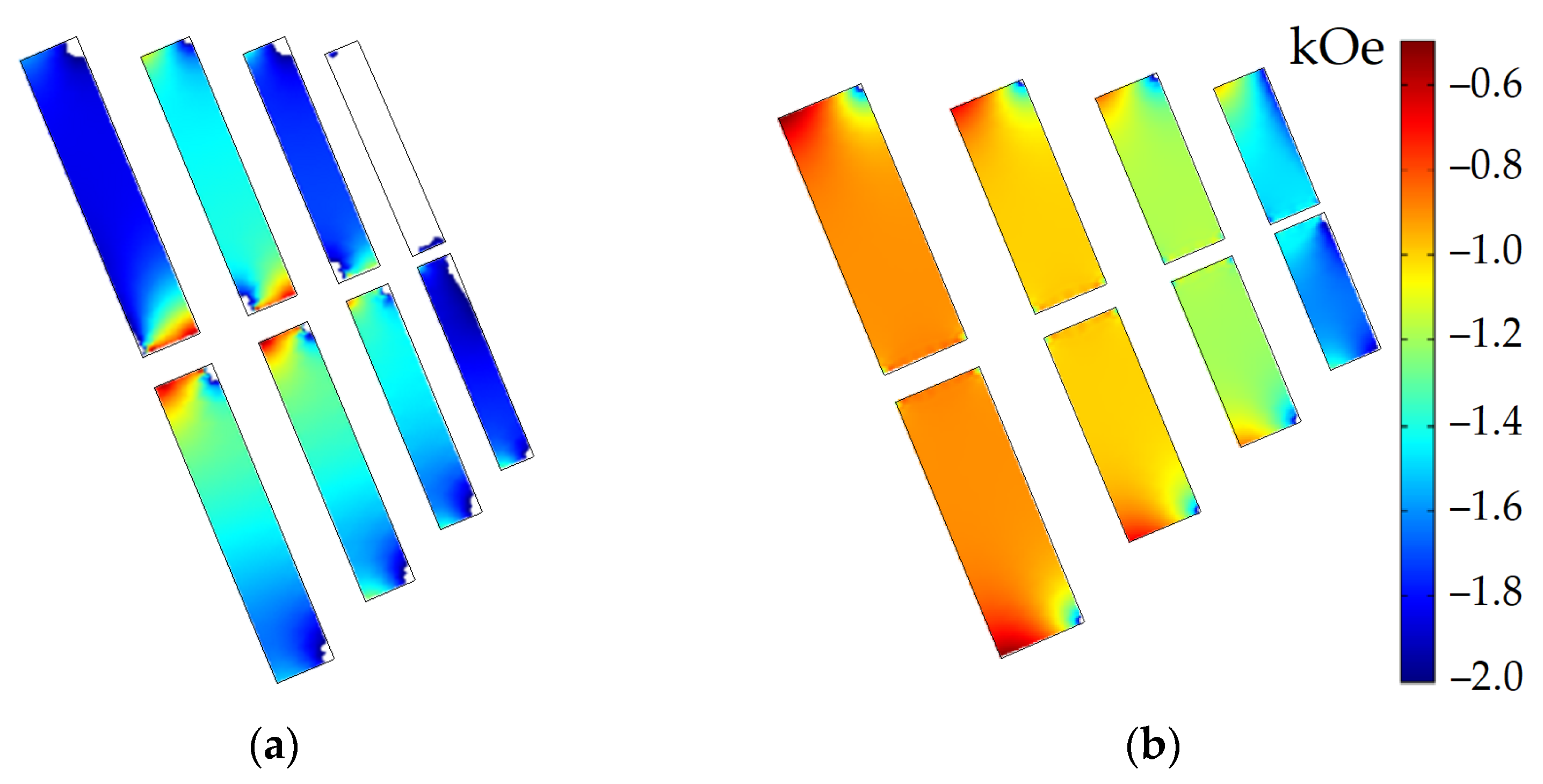
Figure 8 shows the instantaneous magnitude of the magnetic flux density of the design presented in [14] and the new design. Figure 9 shows the minimum value (with maximum absolute value) of the demagnetization field over the machine cycle in operating point 4 since a short-term application of the demagnetization field stronger than the coercivity of the magnets results in their demagnetization. The entire magnet area in the new design is not subjected to the demagnetization field with an absolute value of more than 2.5 kOe, while the large area of the magnets in the design presented in [14] is. The absolute value of the demagnetization field does not exceed 3 kOe in this case.
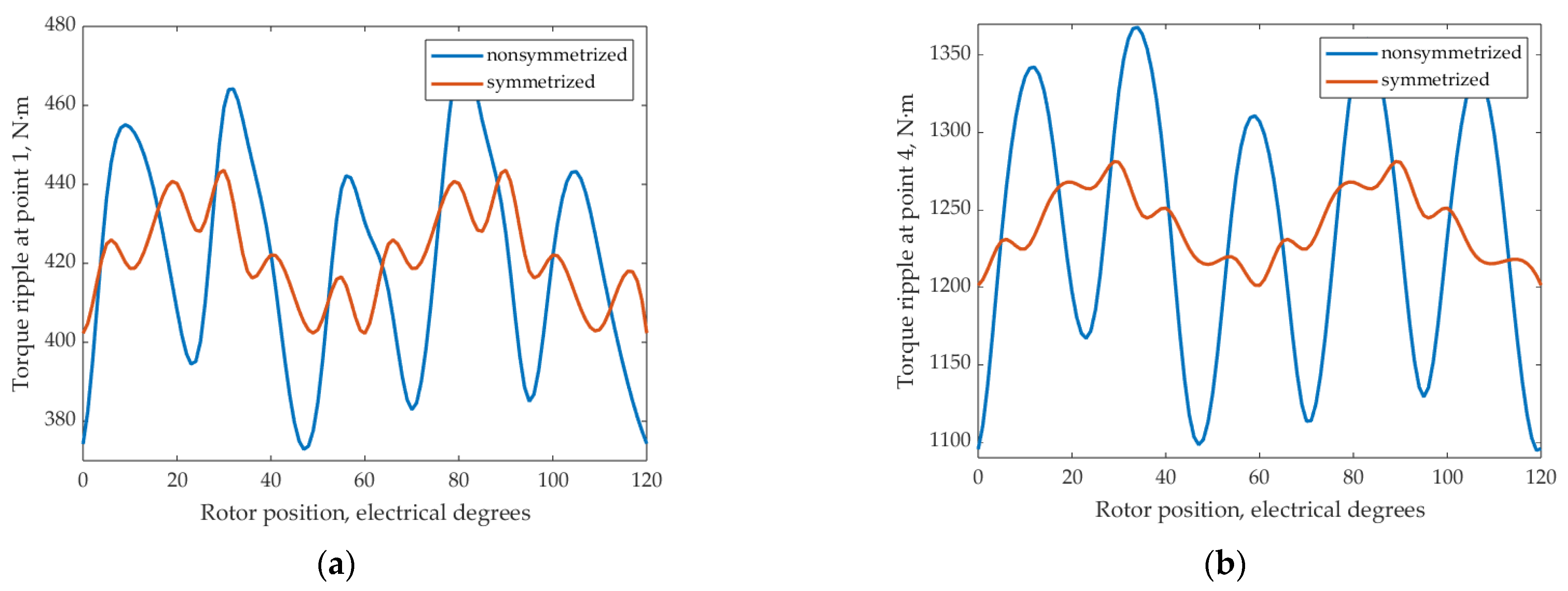
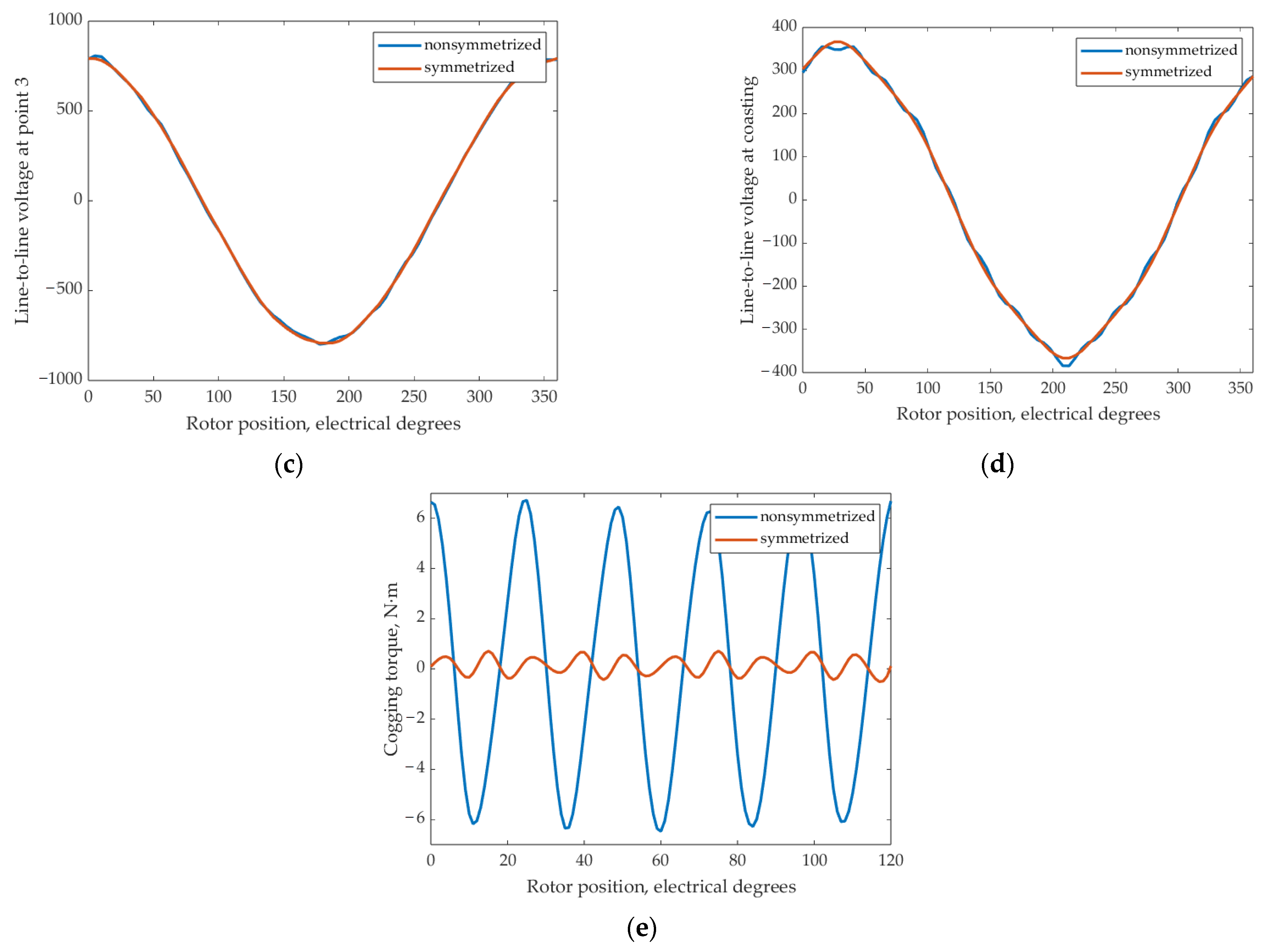
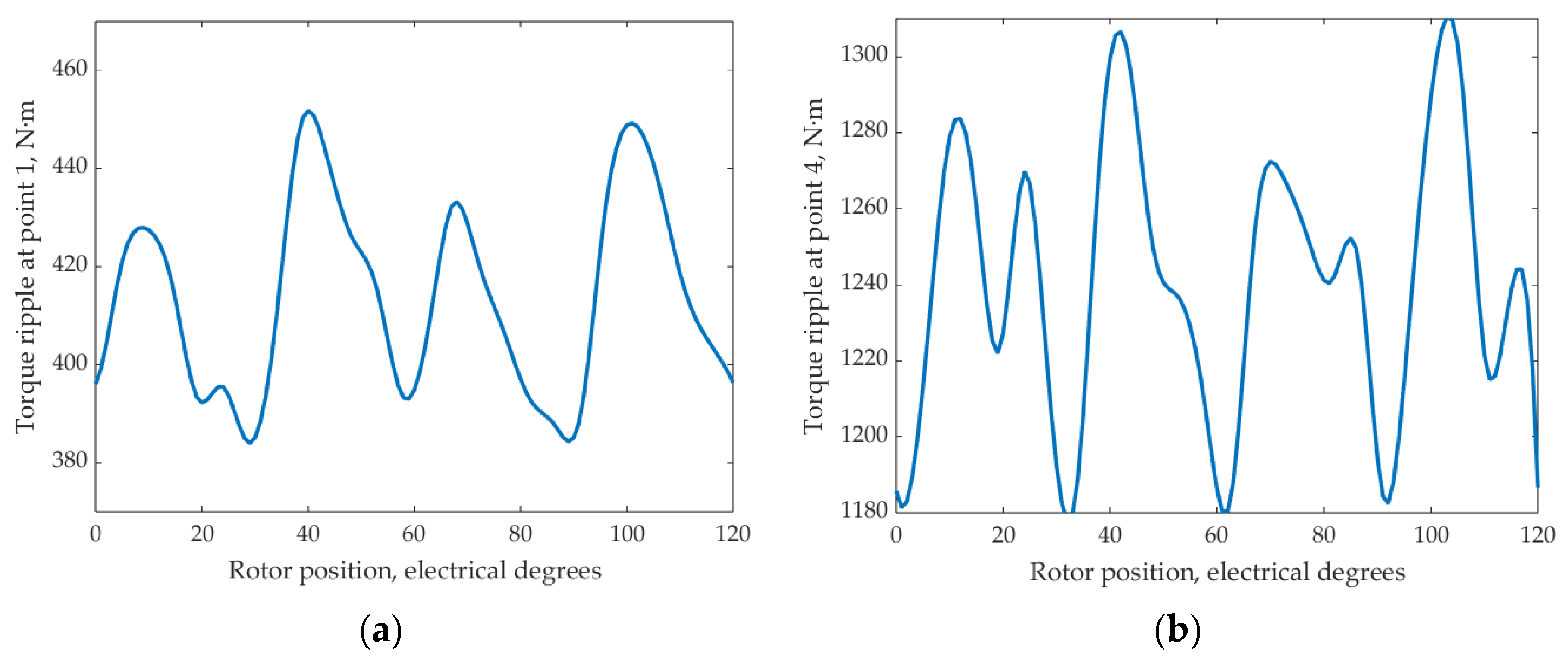
Figure 10 shows the calculated waveforms of the FaSHM: torque ripples at operating points with minimum and maximum torque; cogging torque; back EMF at the operating point where its maximum amplitude is reached, and back EMF at costing.
Comparing the results in Table 6, the differences in the characteristics of the FaSHM design optimized in [14] and the new design are not very large and consist of the following:
(1)
The maximum current decreased slightly by 100%(541 − 539)/541 = 0.4%;
(2)
The main advantage of the new FaSHM design is a significantly increased resistance to demagnetization of magnets. The coercive force of the Y30H-2 magnet is about 4 kOe [35]. In the design optimized in [14], the maximum demagnetizing field is 3 kOe, and the margin is (4 − 3) = 1 kOe. In the new design, the maximum demagnetizing field is 2.5 kOe, and the margin is 1.5. Therefore, we can conclude that the new design is one and a half times more reliable for demagnetization of magnets. This is due to an increase in the width of the magnet (equal to the depth of the rotor slot) from 7.5 cm to 8.3 cm [14]. In addition, the lengths of the stator and rotor lamination have increased, which redistributed the flux over a larger area. Reducing the cross-sections of the housing and sleeve led to an increase in flux density;
(3)
Core losses during coasting have been reduced by 100%(705 − 639)/705 = 9.4%, which contributes to the reduction of the average losses;
(4)
However, due to achieving better reliability with respect to demagnetization, the average losses slightly increased by 100%(7.16 − 7.05)/7.16 = 1.5%.

6. FaSynRM Optimization Parameters and Results

6.1. FaSynRM Optimization Parameters

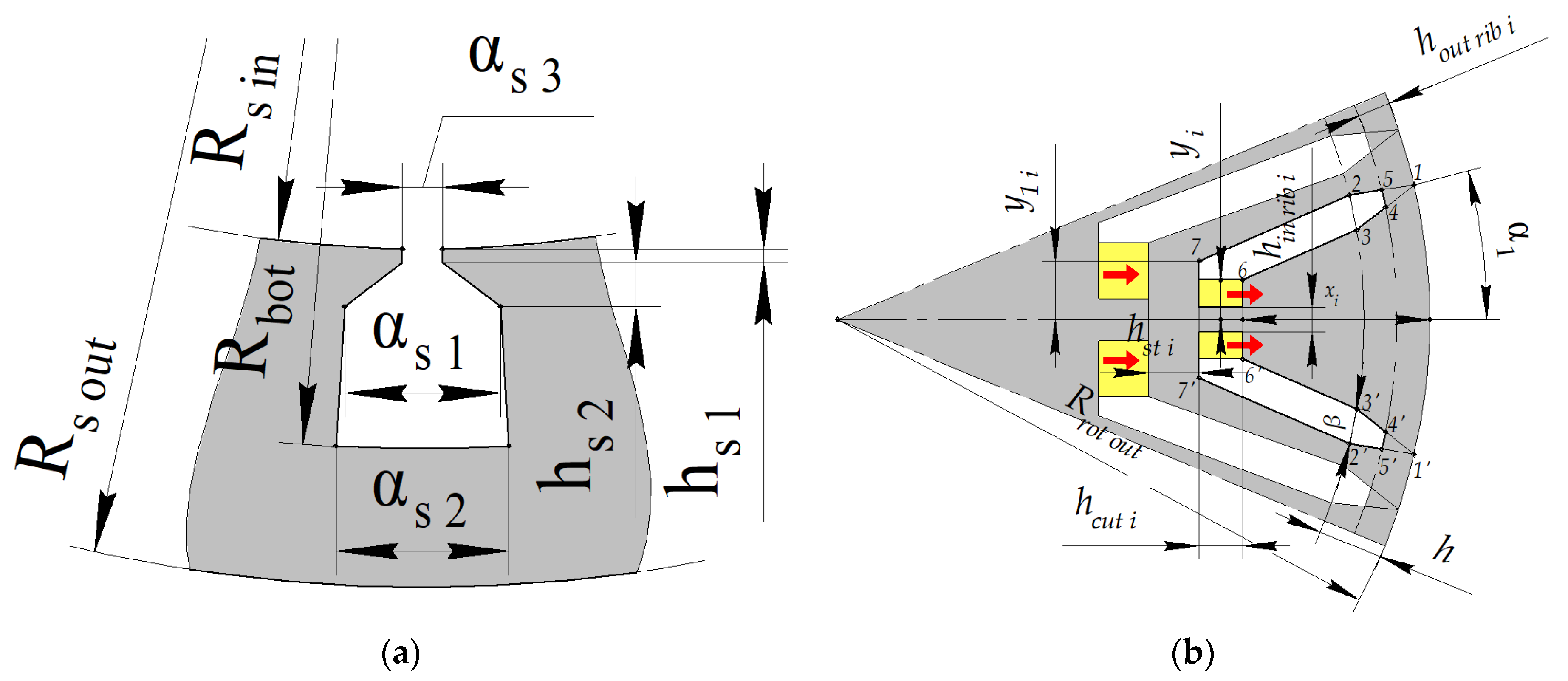
Figure 11 illustrates the parameters that define the FaSynRM geometry. The rotor has 4 magnetic flux barriers per pole. They are numbered 1, 2, 3, 4, starting from the outer barrier and ending with the inner one. The geometry of the magnetic flux barrier is shown in Figure 11b.
The integrity of the rotor is ensured by internal ribs with thickness hin rib i in the middle of each barrier and external ribs with thickness hout rib i, adjoining the air gap. On the surface of the rotor, points at a distance αi of the barrier symmetry axis are 1 and 1′, which define the barrier geometry. Points 2, 2′, 3, 3′ are marked at a distance h from the surface of the rotor. The angular distance between points 2 and 3 and between 2′ and 3′ is equal to β. A circle of 455′4′ at a depth equal to the thickness of the outer ribs hin rib i cuts off triangles 1′4′5′ and 1′4′5′ from the barrier. For the outermost edge, points 6 and 6′ coincide with points 3 and 3′, that is, line 66′ is drawn between points 3 and 3′. With this exception, the depth xi of the line is set to 66′, and the length of this line is 2yi. Line 77′ is drawn at depth (xi + hcut i), where hcut i is the width of the magnetic flux barrier. The length of this line is 2y1i. Line 77′ of the deepest gap limits the area allocated for cutouts in general. Its angular size ε is a fixed parameter. Therefore, the parameter y1i is set only for three external magnetic flux barriers.
In this case, xi+1 = xi + hcut i + hst i, where hst i is the steel thickness deep behind the barrier. Behind barriers 1, 2, 3 are the following barriers. Behind barrier 4 is the circumference of the inner radius of the rotor. To reduce the optimization parameters, we accept the following relations:
αi = a + b(i − 1/2), i = 1, 2, 3, 4;
y1i = yic, i = 1, 2, 3;
yi = y1ig, i = 1, 2, 3, 4;
hcut i = acut i + bcut i(i − 1), i = 1, 2, 3, 4;
hst i = ast i + bst i(i − 1), i = 1, 2, 3, 4.
The ratio of the widths of the stator slot αstat1stat2 also does not change. In addition, the variable parameters include the current control angles in operating points 1, 2, 3, 4. Table 7 shows the FaSynRM parameters that are not changed during the optimization. Table 4 shows the FaSynRM parameters that are varied during the optimization.

6.2. FaSynRM Optimization Results

As Figure 12 shows, the FaSynRM optimization process took 180 calls of the objective function, and its value was significantly reduced.
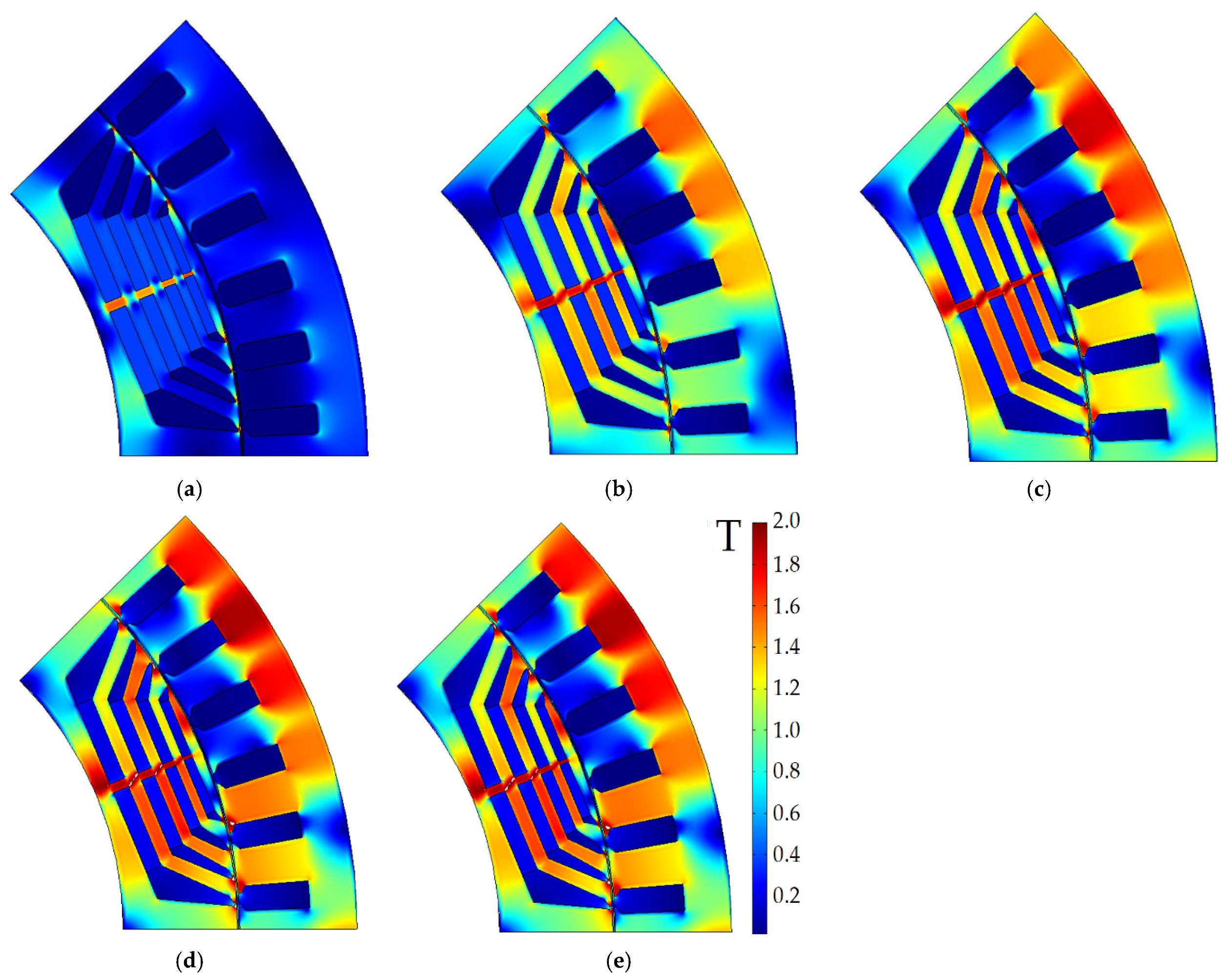
Table 8 shows the characteristics of the initial and optimized FaSynRM designs. In the open-circuit coasting mode, the voltage at the motor terminals in the initial design and after optimization is 171 V and 207 V, respectively. The magnetic loss density is mainly concentrated in the stator magnetic core and is equal to 840 W and 490 W, respectively. Figure 13 shows the FaSynRM geometry and flux density amplitude at operating points 1–5 listed in Table 1. Figure 14 shows the geometry and flux density amplitude after the FaSynRM optimization. Figure 15 shows the demagnetizing field in the area of permanent magnets on the rotor before and after optimization.
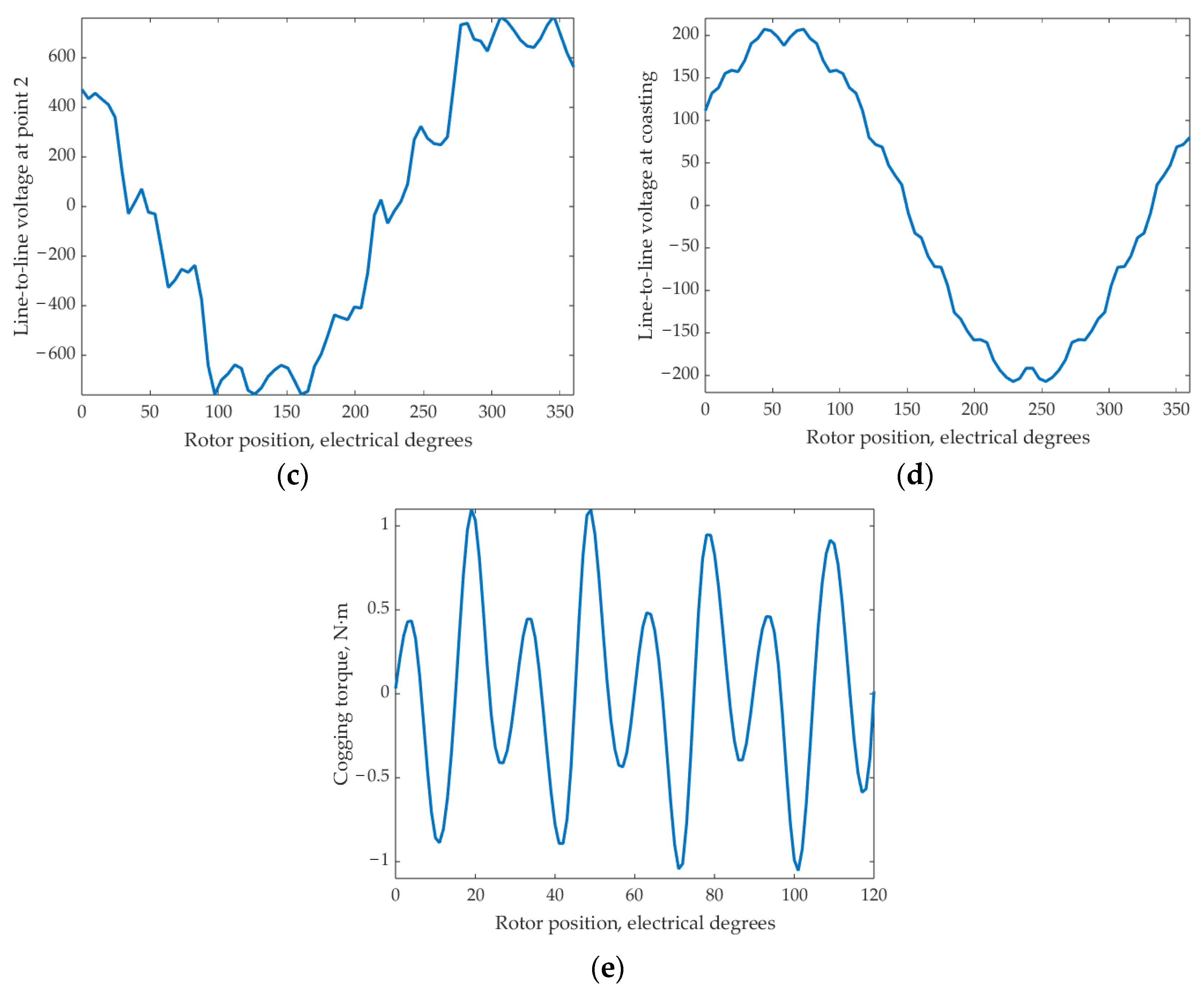
Figure 16 shows the calculated waveforms of the FaSynRM: torque ripples at operating points with minimum and maximum torque; cogging torque; back EMF at the operating point where its maximum amplitude is reached, and back EMF at costing.
Comparing the characteristics of the FaSynRM before and after optimization, we can draw the following conclusions:
(1)
Average losses were reduced by 100%(10.46 − 7.4)/10.46 = 29.3%;
(2)
Maximum armature winding current decreased by 100%(1402 − 839)/1402 = 40%;
(3)
Maximum torque ripple decreased by (33 − 10) = 23%;
(4)
The share of magnets δdemag exposed to a demagnetizing field of more than 2 kOe decreased from 8.6% to almost zero (0.06%). As can be seen from Figure 15, the −2 kOe level is reached only in the corners of the magnets, and it can be concluded that the demagnetization of this small share of magnets is not critical. Therefore, we can conclude that with a coercive force of 4 kOe, the optimized design has a large safety margin (4 − 2) = 2 kOe. The achievement of a higher resistance to demagnetization of the design after optimization, apparently, was facilitated by an increase in the thickness of the magnets, as well as an increase in the number of turns, and hence a decrease in the turn voltage and magnetic flux in the magnetic circuits.

7. Comparison of Characteristics of FaSHM and FaSynRM

This section discusses the comparison of the characteristics of the considered electrical machines after optimization. Table 9 compares the performance of the optimized FaSHM and FaSynRM. The FaSHM characteristics are taken from Table 6. The FaSynRM characteristics are taken from Table 8. Table 10 shows a comparison of masses, dimensions, and active material costs.
Comparing the characteristics of the FaSHM and FaSynRM from Table 9 and Table 10, we can draw the following conclusions:
(1)
In this application, the average loss of the FaSHM is 100%(7.4 − 7.16)/7.4 = 3.4% less than that of FaSynRM;
(2)
By adjusting the excitation flux, the maximum armature current for the FaSHM is 833/539 = 1.54 times less than for the FaSynRM, which potentially makes it possible to significantly reduce the cost of power modules of the traction inverter;
(3)
The active volume of magnetic cores, excluding the stator housing, in the FaSynRM is 100%(47.1 − 45.4)/47.1 = 3.9% higher than in the FaSHM;
(4)
The length of the FaSHM stator laminations is less than that of FaSynRM by 100%(240 − 227)/240 = 5.4%; the length of the FaSHM, taking into account the gap for installing the excitation winding, is greater by 100%(260 − 240)/260 = 7.7%;
(5)
The mass of active materials of the FaSHM is greater than that of the FaSynRM by 100%(359.2 − 98.9 − 241)/(359.2 − 98.9) = 7.4% excluding the housing and sleeve;
(6)
The cost of the FaSHM active materials is 100%(1152.7 − 818.2)/818.2 = 29.0% higher than that of the FaSynRM (excluding the housing and sleeve) due to the greater mass of copper and magnets;
(7)
The maximum modulus of the demagnetizing force in the case of the FaSHM is greater than in the case of the FaSynRM by (2.5 − 2) = 0.5 kOe. In this case, the demagnetization margin for the FaSynRM is (4 − 2) = 2 kOe, and for the FaSHM is (4 − 2.5) = 1.5 kOe, where 4 kOe is the coercive force of ferrite magnets. Therefore, the FaSHM requires a more careful design of control algorithms to avoid demagnetization during failures and transients.

8. Conclusions

The article provides a comparative analysis of the optimized designs of the traction ferrite-assisted synchronous reluctance machine (FaSynRM) and the traction ferrite-assisted synchronous homopolar machine (FaSHM) in a subway train drive with a power rating of 370 kW. The machines have an approximately equal outer diameter of the stator lamination. When optimizing the machines, the train movement cycle is considered. To reduce the computational burden during optimization, the computationally efficient Nelder-Mead method is used. Moreover, each time the optimization function is called, the characteristics of one of these machines are calculated only at 6 operating points, from which, using quadrature formulas, the integral characteristics of the machines can be calculated throughout the whole moving cycle.
The goals of machine optimization are to reduce losses in the train moving cycle, the maximum current of the semiconductor inverter, and the torque ripple. In addition, the goal of optimization is to prevent irreversible demagnetization of the ferrite magnets in the rotor.
For the FaSHM, compared with the FaSynRM, the losses are reduced by 3.4%, and the maximum current of the traction inverter is reduced by 1.54 times. For the FaSynRM, compared to the FaSHM, the active core volume is higher by 3.9%. However, for the FaSynRM, the mass of active materials is reduced by 7.4%, and the cost of active materials is reduced by 29% due to the smaller mass of magnets. Also, the FaSynRM has less risk of irreversible demagnetization of the ferrite magnets in the rotor.
In general, it can be concluded that the machines in question have comparable performance. However, the FaSHM has better field weakening capability, which reduces the maximum current, power, and cost of inverter power modules, while the FaSynRM requires fewer permanent magnets at the same torque density and is more resistant to irreversible demagnetization, which reduces its cost and improves reliability.
Future work will involve conducting a comprehensive comparison of the FaSHM with other types of electrical machines utilized in subway drives and other applications.

Author Contributions

Conceptual approach, V.D. and V.P.; data curation, V.D. and V.K.; software, V.D. and V.P.; calculations and modeling, V.D., V.K. and V.P.; writing—original draft, V.D., V.K. and V.P.; visualization, V.D. and V.K.; review and editing, V.D., V.K. and V.P. All authors have read and agreed to the published version of the manuscript.

Funding

The research funding from the Ministry of Science and Higher Education of the Russian Federation (Ural Federal University Program of Development within the Priority-2030 Program) is gratefully acknowledged.

Institutional Review Board Statement

Not applicable.

Informed Consent Statement

Not applicable.

Data Availability Statement

Data are contained within the article.

Acknowledgments

The authors thank the editors and reviewers for careful reading and constructive comments.

Conflicts of Interest

The authors declare no conflict of interest.

References

  1. Matsuoka, K.; Kondo, M. Energy Saving Technologies for Railway Traction Motors. IEEJ Trans. Electr. Electron. Eng. 2010, 5, 278–284. [Google Scholar] [CrossRef]
  2. De Almeida, A.T.; Ferreira, F.J.; Baoming, G. Beyond Induction Motors—Technology Trends to Move up Efficiency. IEEE Trans. Ind. Appl. 2014, 50, 2103–2114. [Google Scholar] [CrossRef]
  3. Fedoseyev, L.; Pearce, E.M., Jr. Rotor Assembly with Heat Pipe Cooling System. U.S. Patent US9331552B2, 3 May 2016. Available online: https://patents.google.com/patent/US9331552B2/en?oq=US9331552B2 (accessed on 13 August 2023).
  4. Guan, Y.; Zhu, Z.Q.; Afinowi, I.A.A.; Mipo, J.C.; Farah, P. Comparison between induction machine and interior permanent magnet machine for electric vehicle application. In Proceedings of the 2014 17th International Conference on Electrical Machines and Systems (ICEMS), Hangzhou, China, 22–25 October 2014; pp. 144–150. [Google Scholar]
  5. Kim, B.; Lee, J.; Jeong, Y.; Kang, B.; Kim, K.; Kim, Y.; Park, Y. Development of 50 kW traction induction motor for electric vehicle (EV). In Proceedings of the 2012 IEEE Vehicle Power and Propulsion Conference, Seoul, Republic of Korea, 9–12 October 2012; pp. 142–147. [Google Scholar]
  6. Zhu, Z.Q.; Chu, W.Q.; Guan, Y. Quantitative comparison of electromagnetic performance of electrical machines for HEVs/EVs. CES Trans. Electr. Mach. Syst. 2017, 1, 37–47. [Google Scholar] [CrossRef]
  7. Dianov, A. Instant Closing of Permanent Magnet Synchronous Motor Control Systems at Open-Loop Start. Sustainability 2022, 14, 12665. [Google Scholar] [CrossRef]
  8. Schulze, R. Reducing Environmental Impacts of the Global Rare Earth Production for Use in Nd-Fe-B Magnets. How Much Can Recycling Contribute? Ph.D. Thesis, Technical University of Darmstadt, Darmstadt, Germany, December 2018. Available online: https://tuprints.ulb.tu-darmstadt.de/8301/7/Diss%20Rita%20Schulze%2015-12-2018.pdf (accessed on 13 August 2023).
  9. Dong, S.; Li, W.; Chen, H.; Han, R. The status of Chinese permanent magnet industry and R&D activities. AIP Adv. 2017, 7, 056237. [Google Scholar] [CrossRef]
  10. Carraro, E.; Bianchi, N.; Zhang, S.; Koch, M. Design and Performance Comparison of Fractional Slot Concentrated Winding Spoke Type Synchronous Motors with Different Slot-Pole Combinations. IEEE Trans. Ind. Appl. 2018, 54, 2276–2284. [Google Scholar] [CrossRef]
  11. The Net-Zero Materials Transition: Implications for Global Supply Chains, Report, McKinsey & Company, July 2023. Available online: https://www.mckinsey.com/industries/metals-and-mining/our-insights/the-net-zero-materials-transition-implications-for-global-supply-chains (accessed on 13 August 2023).
  12. De Lima, W.I.B. Rare Earth Industry; Elsevier: Amsterdam, The Netherlands, 2015. [Google Scholar]
  13. Papini, F.; Osama, M. Electromagnetic Design of an Interior Permanent Magnet Motor for Vehicle Traction. In Proceedings of the 2018 XIII International Conference on Electrical Machines (ICEM), Alexandroupoli, Greece, 3–6 September 2018; pp. 205–211. [Google Scholar] [CrossRef]
  14. Dmitrievskii, V.; Prakht, V.; Kazakbaev, V. Design Optimization of a Synchronous Homopolar Motor with Ferrite Magnets for Subway Train. Mathematics 2023, 11, 589. [Google Scholar] [CrossRef]
  15. Dobzhanskyi, O.; Grebenikov, V.; Gouws, R.; Gamaliia, R.; Hossain, E. Comparative Thermal and Demagnetization Analysis of the PM Machines with Neodymium and Ferrite Magnets. Energies 2022, 15, 4484. [Google Scholar] [CrossRef]
  16. Manne, B.; Kiran Kumar, M.; B. Akuru, U. Design and Performance Assessment of a Small-Scale Ferrite-PM Flux Reversal Wind Generator. Energies 2020, 13, 5565. [Google Scholar] [CrossRef]
  17. Ibrahim, M.N.; Silwal, B.; Sergeant, P. Permanent Magnet-Assisted Synchronous Reluctance Motor Employing a Hybrid Star-Delta Winding for High Speed Applications. In Proceedings of the 2018 XIII International Conference on Electrical Machines (ICEM), Alexandroupoli, Greece, 3–6 September 2018; pp. 379–385. [Google Scholar]
  18. Liu, Z.; Hu, Y.; Wu, J.; Zhang, B.; Feng, G. A Novel Modular Permanent Magnet-Assisted Synchronous Reluctance Motor. IEEE Access 2021, 9, 19947–19959. [Google Scholar] [CrossRef]
  19. Barcaro, M.; Pradella, T.; Furlan, I. Low-torque ripple design of a ferrite-assisted synchronous reluctance motor. IET Electr. Power Appl. 2016, 10, 319–329. [Google Scholar] [CrossRef]
  20. Du, G.; Zhang, G.; Li, H.; Hu, C. Comprehensive Comparative Study on Permanent-Magnet-Assisted Synchronous Reluctance Motors and Other Types of Motor. Appl. Sci. 2023, 13, 8557. [Google Scholar] [CrossRef]
  21. Liu, X.; Li, Y.; Liu, Z.; Ling, T.; Luo, Z. Analysis and design of a high power density permanent magnet-assisted synchronous reluctance machine with low-cost ferrite magnets for EVs/HEVs. COMPEL-Int. J. Comput. Math. Electr. Electron. Eng. 2016, 35, 1949–1964. [Google Scholar] [CrossRef]
  22. Li, Y.; Yang, H.; Lin, H.; Fang, S.; Wang, W. A Novel Magnet-Axis-Shifted Hybrid Permanent Magnet Machine for Electric Vehicle Applications. Energies 2019, 12, 641. [Google Scholar] [CrossRef]
  23. Prakht, V.; Dmitrievskii, V.; Kazakbaev, V.; Anuchin, A. Comparative Study of Electrically Excited Conventional and Homopolar Synchronous Motors for the Traction Drive of a Mining Dump Truck Operating in a Wide Speed Range in Field-Weakening Region. Mathematics 2022, 10, 3364. [Google Scholar] [CrossRef]
  24. Ren, Z.; Yu, K.; Xin, Q.; Pan, Y. Performance of Homopolar Inductor Alternator with Diode-Bridge Rectifier and Capacitive Load. IEEE Trans. Ind. Electron. 2013, 60, 4891–4902. [Google Scholar] [CrossRef]
  25. Lorilla, L.; Keim, T.; Lang, J.; Perreault, D. Topologies for future automotive generators. Part I. Modeling and analytics. In Proceedings of the 2005 IEEE Vehicle Power and Propulsion Conference, Chicago, IL, USA, 7 September 2005; pp. 74–85. [Google Scholar] [CrossRef]
  26. Orlova, S.; Pugachov, V.; Levin, N. Hybrid Excitation of the Axial Inductor Machine. Latv. J. Phys. Tech. Sci. 2012, 49, 35–41. [Google Scholar] [CrossRef]
  27. Dmitrievskii, V.; Prakht, V.; Anuchin, A.; Kazakbaev, V. Traction Synchronous Homopolar Motor: Simplified Computation Technique and Experimental Validation. IEEE Access 2020, 8, 185112–185120. [Google Scholar] [CrossRef]
  28. Bekhaled, C.; Hlioui, S.; Vido, L.; Gabsi, M.; Lecrivain, M.; Amara, Y. 3D magnetic equivalent circuit model for homopolar hybrid excitation synchronous machines. In Proceedings of the 2007 International Aegean Conference on Electrical Machines and Power Electronics, Bodrum, Turkey, 10–12 September 2007; pp. 575–580. [Google Scholar] [CrossRef]
  29. Asfirane, S.; Hlioui, S.; Amara, Y.; Gabsi, M. Study of a Hybrid Excitation Synchronous Machine: Modeling and Experimental Validation. Math. Comput. Appl. 2019, 24, 34. [Google Scholar] [CrossRef]
  30. Hoang, E.; Lecrivain, M.; Hlioui, S.; Gabsi, M. Hybrid excitation synchronous permanent magnets synchronous machines optimally designed for hybrid and full electrical vehicle. In Proceedings of the 8th International Conference on Power Electronics—ECCE Asia, Seogwipo, Republic of Korea, 30 May–3 June 2011. [Google Scholar] [CrossRef]
  31. Gandzha, S.; Chuyduk, I.; Nazarov, M. Development of a Motor-Wheel Based on a Brushless Machine of Combined Excitation for Hybrid and Electric Transport. In Proceedings of the 2021 International Ural Conference on Electrical Power Engineering (UralCon), Magnitogorsk, Russia, 24–26 September 2021; pp. 630–633. [Google Scholar]
  32. IEC. Specifications for Particular Types of Winding Wires—Part 0–2: General Requirements—Enamelled Rectangular Copper Wire; IEC 60317-0-2:2020; IEC: Geneva, Switzerland, 2020; Available online: https://webstore.iec.ch/publication/63495 (accessed on 13 August 2023).
  33. Lagarias, J.C.; Reeds, J.A.; Wright, M.H.; Wright, P.E. Convergence properties of the Nelder–Mead simplex method in low dimensions. SIAM J. Optim. 1998, 9, 112–147. [Google Scholar] [CrossRef]
  34. Find Minimum of Unconstrained Multivariable Function Using Derivative-Free Method. MATLAB Documentation. © 1994–2023 The MathWorks, Inc. Available online: https://www.mathworks.com/help/matlab/ref/fminsearch.html (accessed on 30 August 2023).
  35. Grades of Ferrite. The Original Online Company. Bunting. E-Magnets. Available online: https://e-magnetsuk.com/ferrite-magnets/grades-of-ferrite/ (accessed on 13 August 2023).
  36. Hard Ferrite Magnets, Product Information, IBSMagnet. 2020. Available online: https://ibsmagnet.com/products/dauermagnete/hartferrit.php (accessed on 13 August 2023).
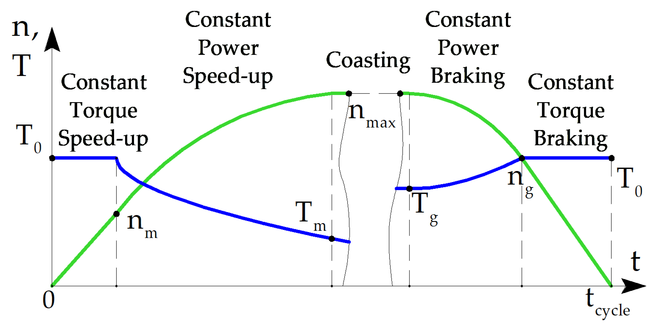
Figure 1. Dynamic speed (green line) and torque (blue line) profiles of the subway train’s traction motor.
Applsci 13 09988 g001
Figure 2. Demanded speed-torque characteristic of the subway train drive. The numbers 0–5 indicate the numbers of operating points of the electric machine, taken into account in the optimization process.
Applsci 13 09988 g002
Figure 3. Motor design representation. Red arrows mark the directions of magnetization of the permanent magnets. (a) Ferrite-assisted synchronous reluctance motor (FaSynRM), 2-Pole area, red, blue and green colors indicate the different phases of the armature winding; (b) Ferrite-assisted synchronous homopolar motor (FaSHM), 1/4 cross-section and stator armature winding layout; (c) 3D cutout view of FaSHM with 1/2 stator cutout and unobstructed rotor.
Applsci 13 09988 g003
Figure 4. Layout of the three-phase inverter with a DC breaker designed to supply the excitation winding; letters A, B, and C represent the armature winding phases.
Applsci 13 09988 g004
Figure 5. Objective function calculation block diagram.
Applsci 13 09988 g005
Figure 6. FaSHM parameters. (a) Stator, the red arrow marks the direction of magnetization of the permanent magnet.; (b) Armature winding; (c) Rotor; (d) Axial plane.
Applsci 13 09988 g006
Figure 7. FaSHM optimization progress.
Applsci 13 09988 g007
Figure 8. The cross-section of the optimized designs of the FaSHM and the plot of flux density magnitudes at operating point 4; saturation areas (>2 T) are shown with white. (a) Design optimized in [14]; (b) New FaSHM design.
Applsci 13 09988 g008
Figure 9. Operating point 4 demagnetizing force (kOe) in the FaSHM permanent magnet zone. Field stronger than −2.5 kOe is not shown (white color is used) (a) Design optimized in [14]; (b) New FaSHM design.
Applsci 13 09988 g009
Figure 10. FaSHM calculated waveforms. (a) Torque ripple at operating point 1; (b) Torque ripple at operating point 4; (c) Line-to-line back EMF at operating point 3 (maximum EMF amplitude); (d) Line-to-line back EMF at coasting (operating point 0); (e) Cogging torque.
Applsci 13 09988 g010aApplsci 13 09988 g010b
Figure 11. Geometric parameters of the FaSynRM. (a) Stator slot; (b) Rotor flux barrier, red arrows mark the direction of magnetization of the permanent magnets. Areas occupied by ferrite magnets are marked in yellow.
Applsci 13 09988 g011
Figure 12. FaSynRM optimization progress.
Applsci 13 09988 g012
Figure 13. FaSynRM cross-section before optimization, with a plot of flux density modulus at saturation limit (>2 T) highlighted in white. (a) Operating point 1; (b) Operating point 2; (c) Operating point 3; (d) Operating point 4; (e) Operating point 5.
Applsci 13 09988 g013
Figure 14. FaSynRM cross-section after optimization, with a plot of flux density modulus at saturation limit (>2 T) highlighted in white. (a) Operating point 1; (b) Operating point 2; (c) Operating point 3; (d) Operating point 4; (e) Operating point.
Applsci 13 09988 g014aApplsci 13 09988 g014b
Figure 15. The demagnetizing field in the area of permanent magnets of the PMaSynRM rotor. Areas with the strongest demagnetization (<−2 kOe) are highlighted in white. (a) Before optimization; (b) After optimization.
Applsci 13 09988 g015
Figure 16. FaSynRM calculated waveforms. (a) Torque ripple at operating point 1; (b) Torque ripple at operating point 4; (c) Line-to-line back EMF at operating point 2 (maximum EMF amplitude); (d) Line-to-line back EMF at coasting (operating point 0); (e) Cogging torque.
Applsci 13 09988 g016aApplsci 13 09988 g016b
Table 1. Points of the operating cycle of the subway train drive considered during the optimization.
Operating Point, iOperating Point NameSpeed ni, rpmTorque, Ti, N∙mwikiwexi
0Coasting mode; maximum speed42800--0.5
1Driving mode; maximum speed4280413.40.3630.970.181
2Braking mode; maximum speed4280826.90.0911.010.046
3Braking mode; changing from constant power to constant torque operation285412400.1821.10.091
4Zero speed012400.1820.970.091
5Driving mode; changing from maximum torque to constant power operation modes142712400.1820.970.091
Table 2. Design features of the FaSHM and the FaSynRM.
ParameterFaSHMFaSynRM
Phase number3
Pole number8
Ferrite magnet gradeY30H-2
Excitation windingYesNo
Number of sets of stator and rotor stacks21
Stator slot number6048
Number of the armature winding layers21
Number of the stator slots per pole and phase q2.52
Rotor slot number4-
Rotor flux barrier number per pole-4
Table 3. Variable FaSHM parameters.
ParameterBefore OptimizationAfter Optimization
Housing thickness h, mm15.614.8
Total stator stacks length Lstator, mm219.6227
Stator slot depth, hp, mm35.931.0
Stator slot width, bp, mm9.07.63
Air gap width δ, mm4.42.98
Rotor slot thickness, α10.423∙tz *0.547∙tz *
Rotor slot thickness, α20.664∙tz *0.706∙tz *
Current angles at operating points 1,2,3,4, electrical radians0.943; 0.921; 0.404; 0.1180.726; 0.834; 0.304; 0.0772
Current ratio **10.559.77
Notes: * the FaSHM rotor tooth pitch tz = 360°/4 = 90 mechanical degrees; ** the current ratio is the ratio of the current in the armature winding layer to the current in the excitation winding cross-section.
Table 4. Variable FaSynRM parameters.
ParameterInitial DesignOptimized Design
Inner stator radius Rstat, m0.20.1943
Stator slot bottom radius Rbot,m0.230.2218
Stator slot thickness αstat10.4∙tz10.622∙tz1
Air gap, mm12.23
ast i, mm46.35
bst i, mm11.59
acut i, mm46.95
bcut i, mm11.64
c1.071.117
g1.071.113
β, rad0.010.021
b0.0777∙αp *0.0755∙αp
Current angle, electrical degrees50; 50; 50; 5066.0; 67.7; 58.2; 55.1
Note: * αp is the FaSynRM pole pitch; tz1 is the FaSynRM stator tooth pitch tz1 = 360°/48 = 7.5 mechanical degrees.
Table 5. FaSHM parameters were unchanged during optimization.
ParameterValue
Machine length excluding winding end parts L, mm260
Stator housing radius, mm267
Axial clearance between excitation winding and rotor, Δa, mm29
Radial clearance between field winding and rotor Δr, mm22
Shaft radius Rshaft, mm40
Stator lamination yoke hs yoke, mm21
Rotor lamination yoke hr yoke, mm17
Stator wedge thickness, ε2, mm2
Stator unfilled area thickness, ε1, mm3
Table 6. FaSHM optimization results.
ParameterDesign Optimized in [14]New Design
Operating Point, i1234512345
Rotational speed n, rpm4280428028540142742804280285401427
Amplitude of the armature phase current Iarm, A370541541529531331536537530532
Efficiency, %95.095.796.5095.795.095.696.4095.5
Output mechanical power Pmech, kW185.3−370.6−370.60185.3185.3−370.6−370.60185.3
Torque, N∙m413.4−826.9−124012401240413.4−826.9−124012401240
Input electrical power, kW195.0−354.8−357.75.6193.6195.0−354.4−357.26.1194.1
Mechanical loss, kW *3.553.551.0600.143.553.551.0600.14
Armature DC copper loss, kW2.204.714.714.494.531.854.834.874.744.78
Armature eddy-current copper loss, kW1.112.701.9900.550.611.781.3300.36
Stator lamination loss, kW2.263.563.8101.903.044.464.5702.12
Rotor lamination loss, kW0.040.090.0700.020.110.230.1900.05
Excitation copper loss, kW0.551.211.211.131.140.511.371.381.321.33
Total loss, kW9.7215.8112.855.628.279.6816.2213.416.068.77
Average losses according to Formula (2), kW7.057.16
Number of turns in armature winding6.585.70
Power factor0.949−0.989−0.9631.00.9060.99−0.99−0.961.000.93
Line-to-line voltage amplitude Varm, V6407587971046768775779211452
Nonsymmetrized torque ripple, %16.315.413.513.613.624.0−22.6−20.521.621.6
Symmetrized torque ripple, %2.502.502.422.612.619.76.96.06.36.2
Magnetic flux density in the housing and the sleeve, T0.300.711.041.151.150.360.761.291.431.43
Note: * Assuming a proportionate relationship, mechanical losses increase with the cube of speed, reaching a maximum of 3.55 kW at nmax.
Table 7. FaSynRM parameters were unchanged during optimization.
ParameterValue
Machine length excluding winding end parts L, mm240
Stator outer radius, mm250
Stator parameter hstat1, mm1
Stator parameter hstat2, mm3
Outer rotor ribs thickness houtrib, mm1
Inner rotor ribs thickness hinrib_i, mm1.5; 2.5; 3.5; 4
Rotor parameter h, mm3
Rotor parameter ε0.8∙αp
Stator slot thickness ratio αstat1stat21.05
Rotor parameter a0.4777∙αp
Table 8. FaSynRM Optimization Results.
ParameterBefore OptimizationAfter Optimization
Operating Point, i1234512345
Rotational speed n, rpm4280428028540142742804280285401427
Amplitude of the armature phase current Iarm, A492886138113931402450693833832839
Efficiency, %91.693.094.1093.494.795.496.0095.3
Output mechanical power Pmech, kW185.30370.60370.600185.30185.30370.60370.600185.30
Torque, N∙m413.4826.91240.00.21240.0413.4826.91240.00.21240.0
Input electrical power, kW202.27344.75348.638.96198.50195.63353.52355.956.22194.42
Mechanical loss, kW *3.553.551.0600.143.553.551.0600.14
Armature DC copper loss, kW1.053.768.968.968.961.764.446.376.226.22
Armature eddy-current copper loss, kW----------
Stator lamination loss, kW11.1416.6110.7503.804.257.886.8902.70
Rotor lamination loss, kW1.241.931.2000.300.771.210.3300.07
Excitation copper loss, kW----------
Total loss, kW16.9725.8521.978.9613.2010.3317.0814.656.229.12
Average losses <Ploss>, kW10.467.40
Number of turns in armature winding5.959.76
Power factor0.8460.6780.60910.6840.9100.7910.73510.769
Line-to-line voltage amplitude Varm, V65475758372976217576659356
Torque ripple, %27293333331616111010
Note: * The mechanical losses are assumed to be proportional to the speed with a maximum value of 3.55 kW at nmax.
Table 9. Comparison of the characteristics of the optimized FaSHM and FaSynRM.
ParameterFaSHMFaSynRM
Operating Point, i1234512345
Rotational speed n, rpm4280428028540142742804280285401427
Amplitude of the armature phase current Iarm, A331536537530532450693833832839
Efficiency, %95.095.696.4095.594.795.496.0095.3
Output mechanical power Pmech, kW185.30370.60370.600185.30185.30370.60370.600185.30
Torque, N∙m413.4826.91240.00.21240.0413.4826.91240.00.21240.0
Input electrical power, kW195.0−354.4−357.26.1194.1195.63353.52355.956.22194.42
Mechanical loss, kW *3.553.551.0600.143.553.551.0600.14
Armature DC copper loss, kW1.854.834.874.744.781.764.446.376.226.22
Armature eddy-current copper loss, kW0.611.781.3300.36-----
Stator lamination loss, kW3.044.464.5702.124.257.886.8902.70
Rotor lamination loss, kW0.110.230.1900.050.771.210.3300.07
Excitation copper loss, kW0.511.371.381.321.33-----
Total loss, kW9.6816.2213.416.068.7710.3317.0814.656.229.12
Average losses <Ploss>, kW7.167.40
Power factor0.990.990.961.000.930.9100.7910.73510.769
Line-to-line voltage amplitude Varm, V687757792114526217576659356
Torque ripple, %9.76.96.06.36.21616111010
Maximum demagnetizing force, kOe2.52
Note: * The mechanical losses are assumed to be proportional to the speed with a maximum value of 3.55 kW at nmax.
Table 10. Comparison of masses, costs, and dimensions of parts of the FaSynRM.
ParameterFaSHMFaSynRM
Stator lamination mass, kg110.5104.6
Rotor lamination mass, kg6678.4
Armature copper mass, kg41.738
Excitation copper mass, kg8.1-
Magnets mass, kg3420
Weight of the rotor sleeve and motor housing without bearing shields, kg98.9-
The total mass of the active materials, rotor sleeve, and motor housing, kg359.2241
Stator lamination cost, USD110.5104.6
Rotor lamination cost, USD6678.4
Armature copper cost, USD291.9266
Excitation copper cost, USD56.7-
Magnets cost, USD627.64369.2
Rotor sleeve and motor housing cost, USD98.9-
The total cost of the active materials (electrical steel, copper, permanent magnets), USD *1152.7818.2
The total cost of the active materials (electrical steel, copper, permanent magnets) and structural steel of the rotor sleeve and motor housing, USD *1251.64818.2
Total length of the stator lamination L, mm227240
Total length of the machine, excluding the winding end parts (including spaces for the excitation coils), mm260-
Stator lamination outer diameter D, mm504.4500
Air gap, mm2.982.23
Active core volume π∙LD2/4, liters45.447.1
* In the analysis, the following material cost assumptions were considered: copper at 7 USD/kg, laminated electrical steel at 1 USD/kg, non-laminated structural steel (for housing and rotor sleeve of the FaSHM) at 1 USD/kg, and Y30H-2 grade ferrite magnet at 18.46 USD/kg [14,36].
Disclaimer/Publisher’s Note: The statements, opinions and data contained in all publications are solely those of the individual author(s) and contributor(s) and not of MDPI and/or the editor(s). MDPI and/or the editor(s) disclaim responsibility for any injury to people or property resulting from any ideas, methods, instructions or products referred to in the content.