Abstract
This paper encapsulates details of the NEMO laser beacon’s design, offering a profound contribution to the field of the time calibration of underwater neutrino telescopes. The mechanical design of the laser beacon, which operates at a depth of 3500 m, is presented, together with the design of the antibiofouling system employed to endure the operational pressure and optimize the operational range, enhancing its functionality and enabling time calibration among multiple towers. A noteworthy innovation central to this development lies in the battery system. This configuration enhances the device’s portability, a crucial aspect in underwater operations. The comprehensive design of the laser beacon, encompassing the container housing, the requisite battery system for operation, electronics, and an effective antibiofouling system, is described in this paper. Additionally, this paper presents the findings of the laser beacon’s qualification process.
1. Introduction
The NEMO (Neutrino Mediterranean Observatory) collaboration [1,2] has been dedicated to research aimed at developing and validating specialized particle detectors [3], specifically a kilometer-scale underwater neutrino telescope [4]. To achieve this goal, the collaboration has diligently explored deep-sea locations suitable for hosting such a detector. The initial step, known as NEMO Phase-1, commenced in 2007. During this phase, a prototype tower was deployed at a depth of 2000 m within a test site situated approximately 20 km off the coast of Catania, Italy. The objective was to test and refine the technology required for the neutrino telescope. After a thorough assessment, a deep-sea site at a depth of 3500 m, located about 80 km offshore of Portopalo di Capo Passero, was identified as the optimal location for the installation of the underwater neutrino telescope. Subsequently, this site was used to house and deploy the ARCA detector [5], one of two KM3NeT telescopes being installed in the Mediterranean Sea [6]. In 2008, a significant milestone was achieved with the deployment of a 100 km electro-optical cable connecting the KM3NeT-It site to an on-shore station situated in Portopalo di Capo Passero. This infrastructure facilitated a series of critical research and development activities focused on validating new technologies in the following years. These endeavors culminated in the construction, deployment, and operation of the NEMO Phase-2 tower in March 2013. This tower was equipped with a laser beacon, a time calibration device evolution of the previous laser beacon used in ANTARES. The purpose of this instrument was to illuminate as many detector nodes as possible, enabling precise time calibration between different lines of detectors. The Phase-2 tower continued to collect data until August 2014, at which point it was disconnected, marking a significant milestone in the NEMO collaboration’s efforts.
Neutrino telescopes employ large volumes of ice or water to detect Cherenkov light from neutrino interactions. These detection systems incorporate arrays of photomultipliers, organized in lines or towers. Ensuring precise synchronization of these photomultipliers is imperative for accurate Cherenkov light identification and timing measurements. While a primary clock signal is distributed to nodes for synchronization purposes, its effectiveness can be hindered by signal deviations and a limited range. Consequently, in situ calibration techniques, such as leveraging downgoing muons, exploiting radioactive Potassium-40 emissions, or employing pulsed light sources with 1 ns precision, become indispensable for achieving synchronization and precise measurements.
Experience gained from the first generation of optical Cherenkov telescopes, such as DUMAND [7,8], Amanda [9], IceCube [10], and ANTARES [11], demonstrates that achieving relative timings on the order of 1 ns is imperative to unlock the full potential of the pointing accuracy of the telescopes. In ANTARES, this milestone was attained through a hybrid approach employing optical beacons, combining both LEDs and lasers. These beacons generated brief light pulses, which were injected into the water and detected by photodetectors located on the same string, as well as on different strings [12]. While the foundational concept of timing calibration remains unchanged, the increased spacing between photodetector strings in a cubic kilometer-scale detector introduces distinct requirements compared to earlier telescopes. Specifically, the variations between “inter-string” and “intra-string” systems emerge. For instance, simpler, lower-intensity devices can be utilized for intra-string calibration [13,14]. In contrast, the augmented spacing between strings, which would exceed three attenuation lengths, necessitates a considerably more intense pulsed light mechanism. The laser beacon provides a solution for generating high-intensity pulses for inter-string calibration. As such, separating the intra/inter-string calibration emerges as the optimal approach. The laser points upwards, projecting its beam through a Lambertian diffuser to make illuminating the maximum detector volume feasible. This configuration allows the laser to effectively perform inter-string calibration, especially by allowing it to illuminate optical modules of different lines with a similar amount of light. Moreover, the laser, positioned in a way to achieve an upward-pointing direction, contributes to intra-string calibration by creating a consistent reference with a fixed position. It also serves as a valuable mechanism to monitor potential string movements or rotations. This approach ensures comprehensive calibration coverage and establishes a reliable baseline for future analyses.
Experience gained from the first generation of optical Cherenkov telescopes, such as DUMAND [7,8], Amanda [9], IceCube [10], and ANTARES [11], demonstrates that achieving relative timings on the order of 1 ns is imperative to unlock the full potential of the pointing accuracy of the telescopes. In ANTARES, this milestone was attained through a hybrid approach employing optical beacons, combining both LEDs and lasers. These beacons generated brief light pulses, which were injected into the water and detected by photodetectors located on the same string, as well as on different strings [12]. While the foundational concept of timing calibration remains unchanged, the increased spacing between photodetector strings in a cubic kilometer-scale detector introduces distinct requirements compared to earlier telescopes. Specifically, the variations between “inter-string” and intra-string systems emerge. For instance, simpler, lower-intensity devices can be utilized for intra-string calibration [13,14]. In contrast, the augmented spacing between strings, which would exceed three attenuation lengths, necessitates a considerably more intense pulsed light mechanism. The laser beacon provides a solution for generating high-intensity pulses for inter-string calibration. As such, separating the intra/inter-string calibration emerges as the optimal approach. The laser points upwards, projecting its beam through a Lambertian diffuser to make illuminating the maximum detector volume feasible. This configuration allows the laser to effectively perform inter-string calibration, especially by allowing it to illuminate optical modules of different lines with a similar amount of light. Moreover, the laser, positioned in a way to achieve an upward-pointing direction, contributes to intra-string calibration by creating a consistent reference with a fixed position. It also serves as a valuable mechanism to monitor potential string movements or rotations. This approach ensures comprehensive calibration coverage and establishes a reliable baseline for future analyses.
This paper outlines the design and characteristics of the laser beacon integrated into the NEMO tower (refer to Figure 1). A comprehensive overview of the laser beacon is provided in Section 2. This paper delves into various facets of the laser beacon’s construction and functionality. Section 3 elaborates on the batteries employed to power the laser beacon. Section 4 expounds on the diffuser. Section 5 details the electronic attenuator, and Section 6 covers the antibiofouling system. The laser head is examined in Section 7. The mechanics and electronics constituting the laser beacon are explored in Section 8 and Section 9, respectively, whereas Section 10 is dedicated to the software aspects. The qualification processes that the laser beacon undergoes are outlined in Section 11. Lastly, this paper concludes with a presentation of the key findings and insights in Section 12.
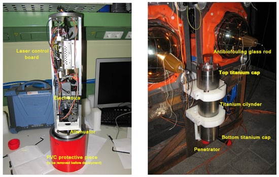
Figure 1.
Laser beacon installed in the NEMO tower. (Left) The laser beacon is open and supported by the rod opening, which is protected by a PCB cap painted in red. It serves as a warning for its removal before deployment. (Right) The laser beacon installed at the base of the tower before deployment.
2. Laser Beacon: General Overview
The primary aim of integrating and testing the proposed laser beacon within the NEMO tower is to facilitate the development of an inter-string calibration system for neutrino telescopes. In addition to this main objective, a concise list of supplementary goals for the integration of the laser beacon into the NEMO tower includes:
- Conducting a practical assessment of the container’s ability to withstand high pressure.
- Establishing effective communication between an external container and the laser beacon system.
- Assessing the reliability of the electronics used in the laser beacon.
- Evaluating the laser’s light emission characteristics, specifically by verifying the distance reached by the emitted light and its temporal attributes, both of which are essential for accurate time calibration purposes in neutrino telescopes.
The central components of the laser beacon encompass several crucial elements:
- The titanium container serves as the structural housing for the laser system.
- The internal aluminum mechanics provide the necessary framework for integrating the various components of the laser beacon.
- A connector enables underwater connectivity, facilitating both the power supply to the laser beacon and external communication.
- The glass rod, coupled with an attached diffuser, effectively scatters the laser light in the desired pattern, preventing the adverse effects of biofouling.
- The electronics component is responsible for supplying power to the laser beacon’s elements. Additionally, it manages operations remotely using the I2C protocol. This control extends to functions such as switching the laser on/off, adjusting the laser emission frequency, and overseeing the filtering level of the electronic attenuator.
- At the heart of the system is the laser itself, specifically a Q-switched Nd-YAG laser, which serves as the primary component responsible for emission.
- An electronic attenuator is integrated to modulate the intensity of the laser beam emitted by the Q-switched Nd-YAG laser.
3. Batteries
One of the key components of the laser beacon is the battery system. The power available in the NEMO tower was not enough to flash the laser, so a battery system was included in the laser beacon. This system can be operated normally, as only a few minutes of operation per week are required. Several models of batteries were analyzed, and finally, the Ni-MH (nickel–metal hydride) [15,16] model was chosen, mainly due to the following reasons:
- Although they have a lower charge density than Li-Ion [17,18] and Li-Po batteries [19,20], Ni-MH batteries do not need a protection circuit to maintain safe operation, reducing the complexity of the circuit.
- They tolerate maintaining a charge even when fully charged, without the need for discharging or half-charging before storage, as required by other technologies.
- They are more economical and ecological than Ni-Cd [21,22] batteries since they do not contain highly polluting cadmium.
- The primary limitation stems from the need to charge using a current that is less than 10% of the load. In this specific scenario, this requirement is indeed an advantage, as it is mandatory to limit the load current due to the input power supplied to the laser beacon being limited to 12 V at 200 mA.
The final rechargeable batteries chosen were the Supreme from Duracell, which are Ni-NM cells with a capacity of 2450 mAh and a voltage of 1.2 V. The main characteristics of the battery are shown in Table 1. To supply enough power to the laser, the battery has to include at least 10 elements or cells, each with a voltage of 1.2 volts. Each cell has a nominal unloaded state value of 1.2 volts; as it charges, this voltage value increases up to 120% of the nominal value. This increase can be seen in Figure 2.

Table 1.
Specifications of the battery chosen for the NEMO laser beacon.
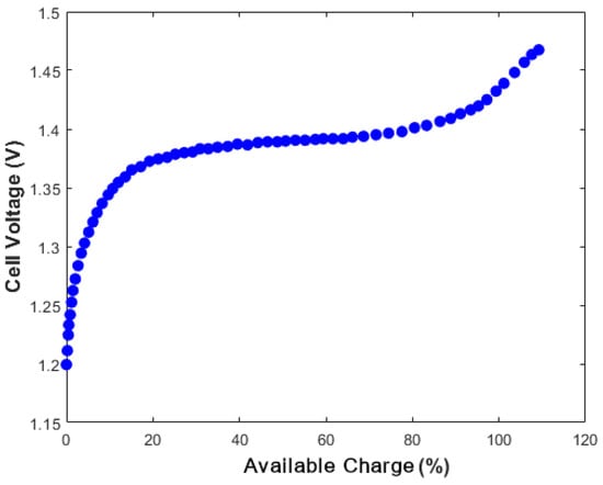
Figure 2.
Charge curve of one nickel–metal hydride battery cell. The nominal value is 1.2 V when it is empty. It increases up to 1.44 V when it is fully charged. The measurement of the voltage is used to determine the percentage of load of the battery.
Therefore, the battery formed by ten cells will have a nominal voltage of 12 V, which will increase up to 14.4 V when the battery is fully charged. The current should not exceed 10% of its capacity. Maintaining the ambient temperature within the range of −20 °C to 60 °C is necessary. Considering that the temperature at the seabed remains stable at 13 °C, this criterion should be met when deployed.
The maximum charging current is then limited to 245 mA. The minimum charging current is limited by the requirements, which specify that the battery should be completely loaded within 72 h. To achieve this requirement, the minimum charge current has to be higher than 34 mAh. This category of rechargeable battery exhibits varying discharge times, influenced by the voltage required from the battery and the discharge current. For the NEMO laser beacon, employing a battery composed of 10 cells will result in a demanded current of under 1.5 A, ensuring operational longevity well beyond the required twenty-minute duration.
4. Diffuser
Encased within a titanium housing, the laser is positioned vertically, emitting its beam in an upward trajectory. This emitted beam is precisely directed toward a Lambertian diffuser, which is glued to the bottom of the glass rod. The ensuing interaction with the diffuser gives rise to a light-scattering phenomenon, thereby engendering an angular distribution characterized by a cosine law () as it emerges from the diffuser’s surface. The selected diffuser, procured from ORIEL, has a diameter measuring 25 mm. The theoretical angular distribution, a function of the diffuser’s inherent properties, is visually represented in Figure 3 (left). In a strategic measure to mitigate the potential risks of laser damage arising from self-reflection, the laser beam is deliberately inclined at a slight angle relative to the vertical axis. Empirical examinations conducted within the laboratory environment have conclusively demonstrated that this minor inclination does not impact the resultant light distribution. The empirical insights gathered through the deployment of the laser head in tandem with the Newport optical meter model 1835C are shown in Figure 3 (right). These empirical observations validate the theoretical underpinnings with empirical evidence.
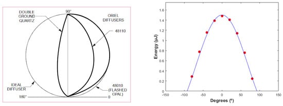
Figure 3.
(Left) 48010 diffuser’s theoretical distribution. (Right) Diffuser’s experimental data (red points) and the Lambertian distribution (blue line). The experimental data perfectly follow the theoretical curve.
5. Electronics Attenuator
In view of the inherent lack of controllability over the laser’s light intensity, the incorporation of a tunable optical filter emerges as a requisite strategy to encompass the entire spectrum of energy [23]. This functionality is facilitated using an optical attenuator, a pivotal component comprising two distinct elements:
- Meadowlark Optics Liquid Crystal Polarizer, Model LVR-100-532: By modulating the voltage applied to the polarizer, the molecular alignment within the crystal can be selectively adjusted, thereby effecting a controlled shift in the polarization orientation of the incident light.
- Beam-Splitter Polarizing Cube of Newport, Model 05FC16PB: Comprising a pairing of right-angle prisms, one of these prisms is coated with a specialized multilayer dielectric material. As the incoming light impinges upon the cube, it undergoes dichotomous separation, with p-polarized light being transmitted and s-polarized light being reflected.
The core mechanism underlying this arrangement hinges upon the polarization manipulation of the laser beam within the crystal, followed by subsequent attenuation as the beam interfaces with the beam splitter. It is important to highlight that the chosen polarizing cube model is optimized to operate within a wavelength range of 420 to 680 nm, ensuring its effectiveness in managing signals within this spectral scope.
6. Antibiofouling System
The phenomenon of biofouling introduces a deleterious impact on the emitted intensity level over time. To circumvent this undesirable effect, an innovative antibiofouling system has been designed and developed. This system encompasses a glass rod characterized by an upper surface rendered in black, confining light propagation to traverse solely through its walls. Consequently, the emitted light remains impervious to the adverse effects of biofouling. The optical characteristics of this system give rise to refraction within the cylindrical walls, precipitating a modification in the polar angle of the emergent light. Should a light ray originating from the diffuser’s central point exhibit an initial polar angle of , its ultimate departure angle upon exiting the glass cylinder can be mathematically described as follows:
Here, n represents the refractive index of water (n = 1.346), and pertains to the refractive index of borosilicate glass ( = 1.4585). As water’s refractive index is lower than that of the glass, the resultant polar angle experiences a reduction. Importantly, the fundamental nature of the light distribution retains its Lambertian profile in line with previous expectations. However, it is noteworthy that the process of refraction results in an overall diminution by a factor of in the quantity of light relative to the distribution that prevails in the absence of the cylindrical element. The dimensions of the cylinder, as well as the insertion of the fixation, dictate the range encompassing the minimum and maximum achievable polar angles. Given that the light emanates from the diffuser’s central point, the establishment of the minimum polar angle (as shown in Figure 4) is contingent upon the vertical length of the cylindrical structure. The relationship governing the minimum polar angle, denoted as , is articulated by the following equation:
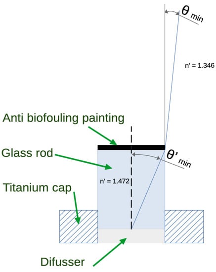
Figure 4.
The minimum polar angle is a function of the length and radius of the cylinder.
In this equation, r signifies the radius of the cylindrical structure, L represents its length, and n and stand for the refractive indices of water and borosilicate glass, respectively. Conversely, to attain a predetermined minimum polar angle, , the corresponding requisite length L of the cylinder can be established through the following equation:
The determination of the appropriate length for the glass cylinder is underpinned by a crucial consideration: ensuring that light effectively reaches the uppermost practical level of the string, as visualized in Figure 5. Conversely, the uppermost attainable polar angle, referred to as the maximum polar angle, , is influenced by both the fixture and the depth at which the cylinder is introduced into the titanium cap, as depicted in Figure 6.
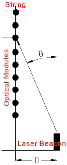
Figure 5.
Vertical reach H of light in a string at distance D from the laser beacon string for a polar angle .
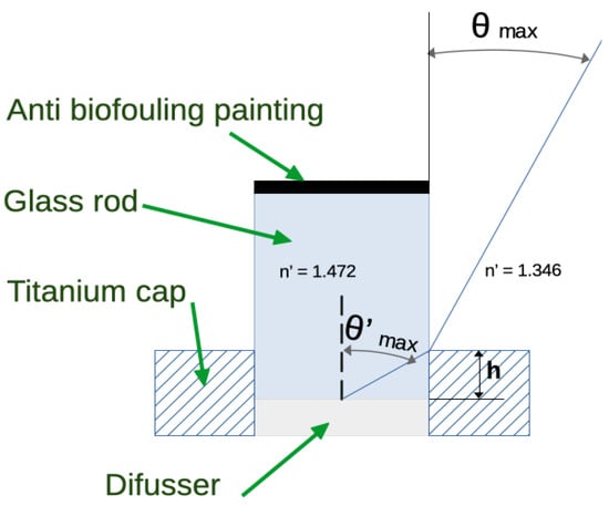
Figure 6.
The maximum polar angle () is imposed by the mechanical fixing.
Mathematically, this maximum polar angle can be expressed as:
where h is the height from the bottom of the cylinder to the top of the fixing (insertion length). Conversely, the maximum height allowed to reach a given is:
With the dimensions of the rod cap and the rod insertion, the following maximum and minimum angles are obtained:
7. Laser Head
The central component of the laser beacon is a pumped Q-switched Nd-YAG diode. A Q-switched laser, also referred to as a quality-switched laser, is designed to emit brief yet potent pulses of light. The technique of Q-switching, alternatively known as giant pulse formation, empowers a laser to generate a pulsed light beam. This method creates light pulses possessing high power levels, significantly surpassing those achievable with the same laser functioning under continuous-wave (CW) operation. When compared to alternative methods of pulse generation within laser systems, Q-switching offers distinct advantages, including the capacity for lower pulse repetition rates, elevated pulse energies, and extended pulse duration. The specific laser apparatus selected for deployment is the Teemphotonics model STG-03E-1S0, a Q-switched Nd-YAG laser renowned for its exemplary performance. This laser emits light with a wavelength of 532 nm and a pulse width of 500 ps.
8. Mechanics
The fundamental mechanical structure of the laser beacon is centered around a titanium container (see Figure 1 for more details). Conceptually, it can be characterized as a cylinder measuring 500 mm in length and a diameter of 142 mm. This container serves as the housing for the laser, electronic attenuator, batteries, and associated electronics, all securely ensconced within an aluminum chassis. The material of choice for the container is grade 5 titanium (Ti6Al4V), a selection justified by its exceptional resistance to marine-based corrosion. A comprehensive overview of the mechanical attributes inherent in grade 5 titanium is provided in Table 2. Comprising three distinct components, the container assembly incorporates a cylindrical tube alongside two caps. The two caps are shown in Figure 7. The uppermost cap accommodates a glass rod, a strategic element that facilitates the egress of light from within the container. Conversely, the lower cap is equipped with a penetrator, affording the essential link to the external environment. Because of the glass rod’s susceptibility during transit, a dedicated protective cover has been thoughtfully devised. This cover, painted in red, serves the dual purpose of enhancing visibility and mandating its removal prior to deployment.
Table 2.
Properties of grade 5 titanium (Ti6Al4V).
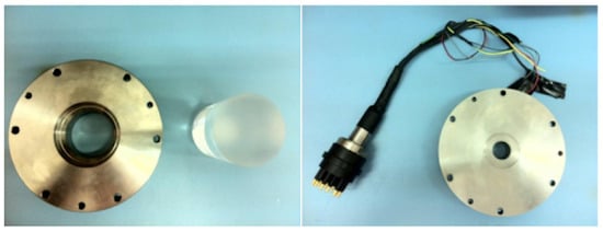
Figure 7.
(Left) Glass rod next to the top cap where it is inserted. (Right) Bottom cap with the connector of the laser beacon.
9. Electronics
The internal components of the laser beacon comprise two primary boards: the power board and the control board. These boards are responsible for supplying, controlling, and monitoring the laser beacon. Detailed descriptions of both boards are provided in the upcoming two subsections.
9.1. Power Board
The power board of the laser beacon is divided into three subsystems:
- Power Circuit: This circuit supplies the necessary power to the various components integrated into the board.
- Optical Attenuation Circuit: This provides the control signals required for the optical attenuator.
- Logic Control Signal Circuit: This circuit generates the control signals for the laser beacon and also manages the battery charge level.
9.1.1. Power Circuit
The power circuit is responsible for charging the battery. To achieve this, the battery, which is composed of 10 cells, is divided into two blocks of 5 cells each. This arrangement enables parallel charging and allows connections in series through relays to power the laser. This design facilitates battery charging without requiring an increase in the input voltage. Furthermore, the use of relays enhances robustness and resilience against overload or current spikes in the circuit’s power supply.
Block A: The input supply provides power to a 12 to 5 V DC/DC converter and another 12 to ±12 V DC/DC converter with dual outputs. The latter converter is dedicated solely to the attenuator. A transistor governs the supply of voltage generated by this DC/DC converter to the attenuator.
Block B: Four double relays manage the parallel charging, series connection for laser activation, and disconnection during standby mode. These relays feature a single coil and two sets of contacts, simultaneously cutting power and ground.
Block C: This block consists of two transistors delivering enough current to energize the relay coils. Additionally, an AND-type logic gate safeguards the circuit and batteries, allowing operation only in the three designated modes: Charge, Laser, and Standby.
Block D: In this block, a 150 mA current limiter is incorporated using an LM317T device. This setup ensures simplicity and versatility, requiring only three components: the LM317T, a resistor, and a capacitor. It maintains a constant current limit, adjustable via resistance variation. The current limit is determined by the following formula:
For a desired limit of 150 mA to charge the batteries, Ohm’s law yields:
Thus, the closest standard resistor value is 8 . This limits the current to 156 mA, divided evenly between the parallel batteries, resulting in about 78 mA per battery.
Block E: This block encompasses the components providing power to the laser beacon. A 9 to 12 V DC/DC converter supplies the laser with power. The DC/DC converter also offers protection against potential power outages or short circuits.
9.1.2. Optical Attenuation Circuit
This subsystem is responsible for supplying and controlling the optical attenuator. The optical attenuator requires a square signal with a frequency of 2 kHz and voltage levels ranging from −10 to 10 V. The subsystem is divided into four blocks:
Block A: This block generates a 2 kHz signal using a 555 timer configured in astable mode. The 555 timer’s output is connected to the base of an NPN-type BJT transistor, which resets the output to zero each time the 555 timer output goes high. The choice of the 555 integrated circuit is due to its robustness, low cost, and ease of implementation. The 2 kHz signal is generated using the following formulas:
where:
- is the positive time interval;
- is the negative time interval;
- 0.693 is a constant;
- and are the resistors to calculate;
- C is the capacitor value.
Block B: This block incorporates a 12-bit resolution DAC controlled via I2C. It operates at 5 V, similar to the 555 timer, and produces a voltage at its output, linked to the input of the differential amplifier in Block C, through I2C frames. This output voltage’s amplitude is configurable via I2C communication. Block B also features two 2.2 kΩ resistors configured as Pull Up for the I2C bus, along with a similar resistor at the DAC’s output.
Block C: This block adapts the signal for the optical attenuator. It combines the signals received from the 555 circuit and the DAC output. The outcome is a 2 kHz square signal modulated in amplitude by the DAC output. A 100 kΩ potentiometer in the inverting amplifier enables fine adjustments, ensuring a maximum VDAC amplitude of 20 Vpp, suitable for the optical attenuator. The resulting signal maintains a 2 kHz frequency and a 20 Vpp amplitude, with variations based on the VDAC amplitude controlled through I2C communication from the control board’s microcontroller.
9.1.3. Logic Signal Control Circuit
This segment of the design is responsible for driving the laser beacon and also monitoring the battery levels. The circuit includes two functional blocks:
Block A: Four logic gates are employed for selecting between internal and external triggers. This choice is determined by a control bit from the microcontroller. When the control bit is low, the internal trigger signal is utilized; otherwise, the external trigger is used. These logic gates exhibit a response time of 4 ns, ensuring minimal distortion of the trigger signal, which must remain stable.
Block B: This subsystem adjusts the battery voltage levels to be compatible with the PIC ADC. An amplifier configured in differential mode, coupled with a resistive divider, enables approximating the battery charge values. The design of the resistive divider emphasizes high impedance to minimize the current flow, thereby reducing battery consumption.
9.2. Control Board
The control board of the laser beacon is responsible for receiving remote commands and interpreting them to control both the laser head and the optical attenuator. Additionally, it generates all the necessary logic signals for their operation. The control board also manages the power board’s operating modes, monitors battery status, and reads the container’s temperature. At the heart of this board is the 16F model 886 family PIC microcontroller. These microcontrollers belong to the RISC architecture [24].
The control board comprises four distinct subsystems, each briefly described below:
Block A: This segment incorporates the PIC microcontroller and an external oscillator essential for the proper functioning of the PIC. The oscillator utilizes a 4 MHz quartz crystal.
Block B: Consisting of a MAX232 integrated circuit, this block handles the adaptation of RS232 communication voltage levels from external sources. It ensures compatibility with the PIC’s voltage requirements.
Block D: Responsible for temperature measurement within the container, this block employs a linear sensor and two amplifiers. The first amplifier operates in follower mode to match the impedance, whereas the second is configured in non-inverting mode to amplify the temperature sensor’s output voltage. To finely adjust the gain, a potentiometer is employed in lieu of a standard resistor.
10. Software
The structure of the laser beacon program follows the typical structure of any microcontroller program. It starts operations with the configuration of microcontroller fuses (configuration bits), port settings, and variable initialization. The program then proceeds with the main program load, where it awaits interrupts. Upon receiving data via the serial port, it stores the data in predefined variables and returns to the main program to execute the scheduled tasks for each command. The description of each program block is presented below.
10.1. Configuration of Fuses and Serial Ports
This block involves the following tasks:
- Declaration of used libraries.
- Definition of microcontroller fuses.
- Configuration setup for both RS232 and I2C serial ports.
10.2. Variable Initialization
This block initializes all the variables used in the program development, along with the required subprograms.
10.3. RS232 Reception Data Available (RDA) Interrupt
Whenever data packets arrive through the serial port, this interrupt is triggered. The RS232 data are stored, and the execution pointer returns to the main program, resuming from the point it was at before the interruption.
10.4. Main Program
The main program awaits data reception through the serial port. Upon receiving and storing RS232 communication data, the main program determines the actions to be taken. The microcontroller then returns to the main program, proceeding from where it was before the interrupt. It verifies whether the received data condition has been met, executes the “Analyze Command” function, and acts based on the received command’s value.
To toggle the laser beacon on or off, a 500-millisecond pulse is generated. This pulse both turns on the laser if it is off and turns it off if it is on. Upon receiving the pulse, the laser’s state changes.
For the selection between an internal or “external trigger”, a pin is set to opt for an external trigger or cleared to choose an internal trigger.
To manage battery control, the program employs four double relays that alternate between the two batteries, configuring them to work in parallel during the charging process and switching to series mode when required to supply power to the laser. In the Standby mode, the circuit is completely disconnected from external power. These relays operate in three distinct modes:
- Charging Mode: Batteries function in parallel.
- Laser Mode: Batteries are configured in series.
- Standby Mode: The circuit is disconnected from external power.
For optical attenuation control, communication via I2C interfaces with a DAC on the power board, allowing the adjustment of the desired attenuation value.
Another essential feature involves monitoring the battery voltage and container temperature. An integrated ADC in the PIC is employed to measure both of these values.
11. Laser Beacon Qualification
11.1. Laser Energy
To quantify the energy of the emitted light pulses, an OPHIR PD10 head in conjunction with the OPHIR LaserStar system is employed. This setup is capable of accurately measuring the energy of individual laser pulses. The precision of this device is higher than 1 nJ. Figure 8 displays the energy per pulse over the initial 20 h of operation at a trigger frequency of 1 kHz (left), along with a histogram depicting the energy distribution (right).
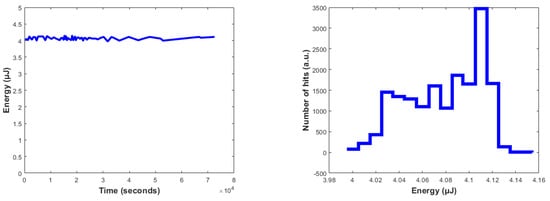
Figure 8.
(Left) Energy per pulse during the first 20 h after switch-on with a trigger frequency of 1 kHz. (Right) Energy histogram.
11.2. Photodiode Signal
The readout system serves to capture the Photodiode (PD) signal originating from the laser. This system is positioned externally to the laser container, specifically within the control module of a separate substructure, distinct from the installation site of the laser beacon. The PD signal, once received, undergoes adaptation to match the anticipated value required by the readout system (inverted and attenuated). Subsequently, the signal is transmitted through a shielded cable in a twisted-pair configuration.
In the laser head, a PD is integrated to provide the precise timing of light emission. This PD generates a positive signal characterized by a 22 ns rise time. To measure the signal jitter, an external PD (specifically, a Newport 812-20 PD with a rise time under 200 ps) exposed directly to the laser beam was employed. The obtained jitter measurements are presented in Figure 9.
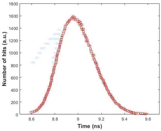
Figure 9.
Jitter of the laser head’s internal PD, which was measured with respect to an external PD with a rise time lower than 200 ps.
11.3. Qualification Laser Beacon Container
To verify the structural integrity and seal effectiveness of the titanium container within the laser beacon, pressure tests were conducted. These tests simulated conditions akin to the ones the container will experience when installed at a depth of 3000 m. The evaluation was performed in collaboration with the company NC Hyperbaric, situated in Burgos, Spain. Utilizing a hyperbaric chamber, the internal pressure was incrementally elevated to 350 bars, equivalent to the pressure endured at a depth of 3500 m. The outcomes of this examination are depicted in Figure 10.
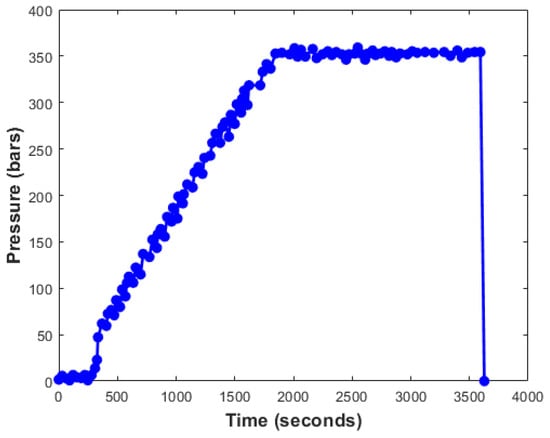
Figure 10.
Pressure tests performed on the laser beacon container.
12. Conclusions
A detailed overview of the design and features of a laser beacon integrated into the NEMO tower for the KM3NeT project has been presented, together with the results of the qualification. The pivotal constituents of the laser beacon have been presented, including the batteries, diffuser, electronic attenuator, antibiofouling system, and laser head. This article delves into the mechanical aspects of the laser beacon, showcasing a titanium container designed to withstand marine corrosion. The use of batteries enhances the portability of the laser beacon, and the results of this study show that Mi-MH batteries achieve the best performance for the operation of the laser beacon. A study of the antibiofouling system has also been presented. The rod design allows for the emission of light that will not be disturbed by biofouling, while the minimum and maximum emissions angles have been optimized to maximize the light range. guarantees that the light will reach the optical modules of the tower where the laser beacon is installed, whereas guarantees that the light of the laser beacon will reach the lower stories of nearby towers. The qualification has proved that the laser beacon container can sustain a pressure of 350 bars. The internal PD has a jitter of less than 0.5 ns, providing precise timing. Finally, the qualification has shown that the laser heads emit pulses of about 4 J in a stable manner. These insights contribute significantly to the advancement of optical calibration systems for underwater neutrino telescopes.
Author Contributions
The individual contribution of each author is as follows: Conceptualization, D.R. and A.S.L.; methodology, D.R.; software, A.D.; validation, D.R., A.S.L. and D.C.; formal analysis, F.S.G.; investigation, D.R.; resources, A.S.L.; data curation, F.S.G.; writing—original draft preparation, D.R.; writing—review and editing, D.R.; visualization, A.D.; supervision, D.R.; project administration, A.S.L.; funding acquisition, A.S.L. and F.S.G. All authors have read and agreed to the published version of the manuscript.
Funding
This research was funded by the Ministerio de Ciencia e Innovación: Programa Estatal para Impulsar la Investigación Científico-Técnica y su Transferencia (refs. PID2021-124591NB-B-C41) (MCIU/FEDER); the Programa de Planes Complementarios I+D+I (refs. ASFAE/2022/023); Generalitat Valenciana: Prometeo (PROMETEO/2020/019); the Grisolía (ref. GRISOLIAP/2021/192) and GenT (refs. CIDEGENT/2018/034, /2020/049, /2021/23) programs; and the EU: MSC program (ref. 101025085), Spain.
Institutional Review Board Statement
Not applicable.
Informed Consent Statement
Not applicable.
Data Availability Statement
Data available on request due to restrictions eg privacy or ethical.
Conflicts of Interest
The authors declare no conflict of interest. The funders had no role in the design of the study; in the collection, analyses, or interpretation of data; in the writing of the manuscript; or in the decision to publish the results.
References
- Riccobene, G. NEMO: NEutrino Mediterranean Observatory. In Astrophysical Sources of High Energy Particles and Radiation; Shapiro, M.M., Stanev, T., Wefel, J.P., Eds.; Springer: Dordrecht, The Netherlands, 2001; pp. 355–361. [Google Scholar] [CrossRef]
- Capone, A.; Aiello, S.; Aloisio, A.; Ameli, F.; Amore, I.; Anghinolfi, M.; Anzalone, A.; Barbarino, G.; Barbarito, E.; Battaglieri, M.; et al. Recent results and perspectives of the NEMO project. Nucl. Instrum. Methods Phys. Res. Sect. A Accel. Spectrom. Detect. Assoc. Equip. 2009, 602, 47–53. [Google Scholar] [CrossRef]
- Giachero, A.; Gironi, L. Special Issue on Development and Application of Particle Detectors. Appl. Sci. 2022, 12, 9380. [Google Scholar] [CrossRef]
- Palladino, A.; Spurio, M.; Vissani, F. Neutrino Telescopes and High-Energy Cosmic Neutrinos. Universe 2020, 6, 30. [Google Scholar] [CrossRef]
- Coniglione, R. KM3NeT-ARCA project status and plan. EPJ Web Conf. 2016, 116, 11003. [Google Scholar] [CrossRef]
- Adrian-Martinez, S.; Ageron, M.; Aharonian, F.; Aiello, S.; Albert, A.; Ameli, F.; Anassontzis, E.; Andre, M.; Androulakis, G.; Anghinolfi, M.; et al. Letter of intent for KM3NeT 2.0. J. Phys. G 2016, 43, 084001. [Google Scholar] [CrossRef]
- Learned, J.; Spiering, C. DUMAND and the Origins of Large Neutrino Detectors. CERN Courier 2016, 25–28. Available online: https://cds.cern.ch/record/2232600/files/vol56-issue6-p025-e.pdf (accessed on 31 August 2023).
- Roberts, A.; Blood, H.; Learned, J.; Reines, F. Status and aims of the DUMAND neutrino project: The ocean as a neutrino detector. In Proceedings of the International Neutrino Conference, Aachen, Germany, 8–12 June 1976. [Google Scholar]
- Andres, E.; Askebjer, P.; Barwick, S.W.; Bay, R.; Bergström, L.; Biron, A.; Booth, J.; Bouchta, A.; Carius, S.; Carlson, M.; et al. The AMANDA neutrino telescope: Principle of operation and first results. Astropart. Phys. 2000, 13, 1–20. [Google Scholar] [CrossRef]
- Aartsen, M.G.; Ackermann, M.; Adams, J.; Aguilar, J.A.; Ahlers, M.; Ahrens, M.; Altmann, D.; Andeen, K.; Anderson, T.; Ansseau, I.; et al. The IceCube Neutrino Observatory: Instrumentation and Online Systems. JINST 2017, 12, P03012. [Google Scholar] [CrossRef]
- Ageron, M.; Aguilar, J.; Al Samarai, I.; Albert, A.; Ameli, F.; André, M.; Anghinolfi, M.; Anton, G.; Anvar, S.; Ardid, M.; et al. ANTARES: The first undersea neutrino telescope. Nucl. Instrum. Methods Phys. Res. Sect. A Accel. Spectrom. Detect. Assoc. Equip. 2011, 656, 11–38. [Google Scholar] [CrossRef]
- Ageron, M.; Aguilar, J.A.; Albert, A.; Ameli, F.; Anghinolfi, M.; Anton, G.; Anvar, S.; Ardellier-Desages, F.; Aslanides, E.; Aubert, J.J.; et al. The ANTARES Optical Beacon System. Nucl. Instrum. Meth. A 2007, 578, 498–509. [Google Scholar] [CrossRef]
- Real, D.; Calvo, D.; Díaz, A.; Salesa Greus, F.; Sánchez Losa, A. A Narrow Optical Pulse Emitter Based on LED: NOPELED. Sensors 2022, 22, 7683. [Google Scholar] [CrossRef] [PubMed]
- Aiello, S.; Albert, A.; Alshamsi, M.; Garre, S.A.; Aly, Z.; Ambrosone, A.; Ameli, F.; Andre, M.; Androulakis, G.; Anghinolfi, M.; et al. Nanobeacon: A time calibration device for the KM3NeT neutrino telescope. Nucl. Instrum. Methods Phys. Res. Sect. A Accel. Spectrom. Detect. Assoc. Equip. 2022, 1040, 167132. [Google Scholar] [CrossRef]
- Johannsen, J. Nickel-metal hydride batteries: Principles and applications. J. Power Sources 2002, 110, 1–10. [Google Scholar]
- Linden, D.; Reddy, T.B. Handbook of Batteries, 4th ed.; McGraw-Hill Professional: Sydney, Australia, 2010. [Google Scholar]
- Goodenough, J.B.; Park, K.S. The Li-ion rechargeable battery: A perspective. J. Am. Chem. Soc. 2013, 135, 1167–1176. [Google Scholar] [CrossRef] [PubMed]
- Scrosati, B.; Garche, J. (Eds.) Lithium-Ion Batteries: Advances and Applications; John Wiley & Sons: Hoboken NJ, USA, 2010. [Google Scholar]
- Zhao, Y.; He, Y.B. Lithium polymer battery. In Lithium-Ion Batteries; Springer: Berlin, Germany, 2016; pp. 307–322. [Google Scholar]
- Hammoud, A.S.; Sabbah, R. (Eds.) Lithium-Polymer Batteries: Science and Technologies; CRC Press: Boca Raton, FL, USA, 2018. [Google Scholar]
- Barlow, F.C.; Cox, R.A. The nickel-cadmium battery. J. Power Sources 1975, 1, 287–302. [Google Scholar]
- Christensen, P.A.; Hamnett, A. (Eds.) Nickel-Cadmium Batteries: Principles and Applications; Elsevier: Amsterdam, The Netherlands, 2012. [Google Scholar]
- Real, D.; Calvo, D.; Díaz, A.; Garre, S.A.; Carretero, V.; Losa, A.S.; Greus, F.S. An Ultra-Narrow Time Optical Pulse Emitter based on a Laser: UNTOPEL. IEEE Trans. Nucl. Sci. 2023. [Google Scholar] [CrossRef]
- Flynn, M.; Flynn, M.J. Computer Architecture: Pipelined and Parallel Processor Design; Computer Science Series; Jones and Bartlett: Burlington, MA, USA, 1995. [Google Scholar]
Disclaimer/Publisher’s Note: The statements, opinions and data contained in all publications are solely those of the individual author(s) and contributor(s) and not of MDPI and/or the editor(s). MDPI and/or the editor(s) disclaim responsibility for any injury to people or property resulting from any ideas, methods, instructions or products referred to in the content. |
© 2023 by the authors. Licensee MDPI, Basel, Switzerland. This article is an open access article distributed under the terms and conditions of the Creative Commons Attribution (CC BY) license (https://creativecommons.org/licenses/by/4.0/).