Article

Research on Constitutive Model and Algorithm of High-Temperature-Load Coupling Damage Based on the Zienkiewicz–Pande Yield Criterion

1
Nanchang Rail Transit Group Co., Ltd., Nanchang 330013, China
2
Institute of Road and Bridge Engineering, Dalian Maritime University, Dalian 116026, China
*
Author to whom correspondence should be addressed.
Appl. Sci. 2023, 13(17), 9786; https://doi.org/10.3390/app13179786
Submission received: 13 July 2023 / Revised: 18 August 2023 / Accepted: 20 August 2023 / Published: 29 August 2023
(This article belongs to the Section Civil Engineering)

Abstract

:
The mechanical properties of rock can be weakened under the influence of high temperatures. To describe the mechanical behavior of rock under the action of high temperature more accurately, based on the Zienkiewicz–Pande yield criterion, the damage variable Dc which accounts for the coupling between high temperature and load is introduced. According to plastic potential theory and plastic flow law, the iterative incremental method for a high-temperature and load-coupled damage constitutive model in Flac3D is deduced in detail and compiled into the corresponding dynamic link library file (.dll file). By modifying the shape function to degenerate into the Mohr–Coulomb constitutive model, an elastic–plastic analysis of an ideal circular tunnel is performed, and a comparison is made between calculation results obtained from the built-in Mohr–Coulomb constitutive model in Flac3D, proving the correctness of the secondary development program. Finally, numerical simulations are conducted to study the effects of high-temperature damage using rock uniaxial compression tests, and the model’s validity is established by comparing it with previous experimental results.

1. Introduction

Based on existing research, the higher temperature of fires can reach and exceed 1000 °C [1]. When a fire occurs, high temperatures may cause irreversible damage to rock, resulting in the reduction in macroscopic physical and mechanical properties [1,2,3]. For tunnel fires, high-temperature damage inevitably affects a tunnel’s bearing capacity and stability [4]. Therefore, the corresponding damage constitutive model has been established to accurately depict the mechanics of rock behavior in these scenarios, holding immense importance for related engineering fires and post-disaster safety assessment.
Regarding the impact of high-temperature damage on the physical mechanics of rocks, Lu et al. showed that as the temperature rises, there is a decrease in tensile strength [5]. Similarly, in an investigation into the effects of high-temperature treatment on sandstone, Xi et al. heated sandstone to different temperatures and then cooled it using natural cooling, water cooling, and liquid nitrogen (LN2); they discussed the evolution of thermal shock damage and its damage mechanism in high-temperature rock when subjected to different cooling methods [6]. The results indicate that heat and cooling treatment have a notable impact on the mechanical properties of rocks. As the processing temperature increases, the dynamic peak stress and strain decrease. Huang et al. studied the physical and mechanical parameters of granite specimens processed at high temperatures and showed the following: with the increase in temperature, the volume of granite expands, the mass decreases, the density decreases, and the absolute value of the three rates of change increases with the rising temperatures [7]. Wang et al., through various experiments, studied the physical and mechanical properties of sandstone after being subjected to high-temperature treatment and standing for different durations and obtained the effect of different temperatures on the properties of sandstone after high-temperature damage [8]. The above studies show that the detrimental impact of high-temperature damage on the mechanical properties of the rock mass should not be overlooked.
In the study of the damage constitutive model, many scholars have used mathematical analysis methods [9], numerical methods [10], and experimental methods [11] to describe the mechanical behavior of rock damage from macro- and micro-perspectives and have established corresponding mathematical and physical models [12,13,14,15,16,17,18]. Wen et al. classified the rock into three segments: intact material, impaired material, and micro-defects [19]. They redefined the damage variable from the standpoint of energy dissipation and introduced the influencing factor of the correlation between damaged materials and micro-defects. Using fitting logistics, the damage evolution equation obtained by the function was used to quantify the impact of energy dissipation on the spread of micro-defects. Liu et al. applied the energy release rate to the traditional elastic stress–strain relationship and assumed that the microscopic strength of the rock satisfies the Weibull distribution [20]. Conventional triaxial tests have demonstrated the model’s ability to accurately depict the evolution of damage in the surrounding rock, thereby providing a robust representation of its behavior. Ma and Gutierrez proposed a constitutive model that accounts for the coupled behavior of plasticity and damage, while also considering the poroelastic effect through the incorporation of effective stress space coupling for the plastic mechanism and the damage mechanism of post-peak softening. The triaxial compression test showed that the shear process can predicted by the model. Characteristics of stress–strain behavior, effective stress paths, and pore pressure variations were apparent in medium shale specimens [21]. Zhu developed a constitutive model for crack evolution damage based on micromechanics, which was used to simulate the stress–strain behavior of rocks exhibiting damage [22].
There has been a significant advancement in the research of constitutive models considering high temperature load coupled with damage in rocks. Yang et al. studied the dynamic changes in micropore structure within a fractured rock mass, evaluated using the Mori–Tanaka and David–Zimmerman models, incorporating the influence of thermomechanical coupling [23]. Guo Xuan et al. introduced damage theory based on thermodynamic potential function, established a superplastic damage constitutive framework for a new structure, and produced the plastic dissipation function or yield function under the condition of pressure and temperature change [24]. Peng et al. proposed a GSI softening model based on the Hoek–Brown yield criterion to characterize the strength behavior of thermally damaged rocks [25]. Xu and Karakus developed a comprehensive thermal–mechanical damage model for granite development, utilizing the Drucker–Prager yield criterion and incorporating the Weibull distribution and the Lemaitre strain equivalence principle [26].
At present, most of the yield criteria used in the research of damage constitutive models by most scholars have sharp points or edges on the yield surfaces. There are edges and corners; the Mohr–Coulomb yield criterion has edges and sharp points, and the Hoek–Brown yield criterion and the aforementioned yield criteria do not take into account the effects of intermediate principal stress and pure hydrostatic pressure [27,28]. The difficult nature of sharp points and edges on the yield surface is not conducive to numerical calculation. By incorporating the Sienkiewicz–Pande yield criterion and accounting for the impact of high-temperature damage, a constitutive model is developed to characterize the elastic–plastic behavior of rocks under high-temperature-load coupling conditions. Furthermore, the incremental iterative algorithm of the corresponding damage constitutive model is deduced, the secondary development is carried out with Visual Studio C++, and the numerical simulation verification is carried out using Flac3D. The proposed constitutive model’s accuracy is validated through a comparison with the relevant literature, and its logical consistency is validated through experimental results.

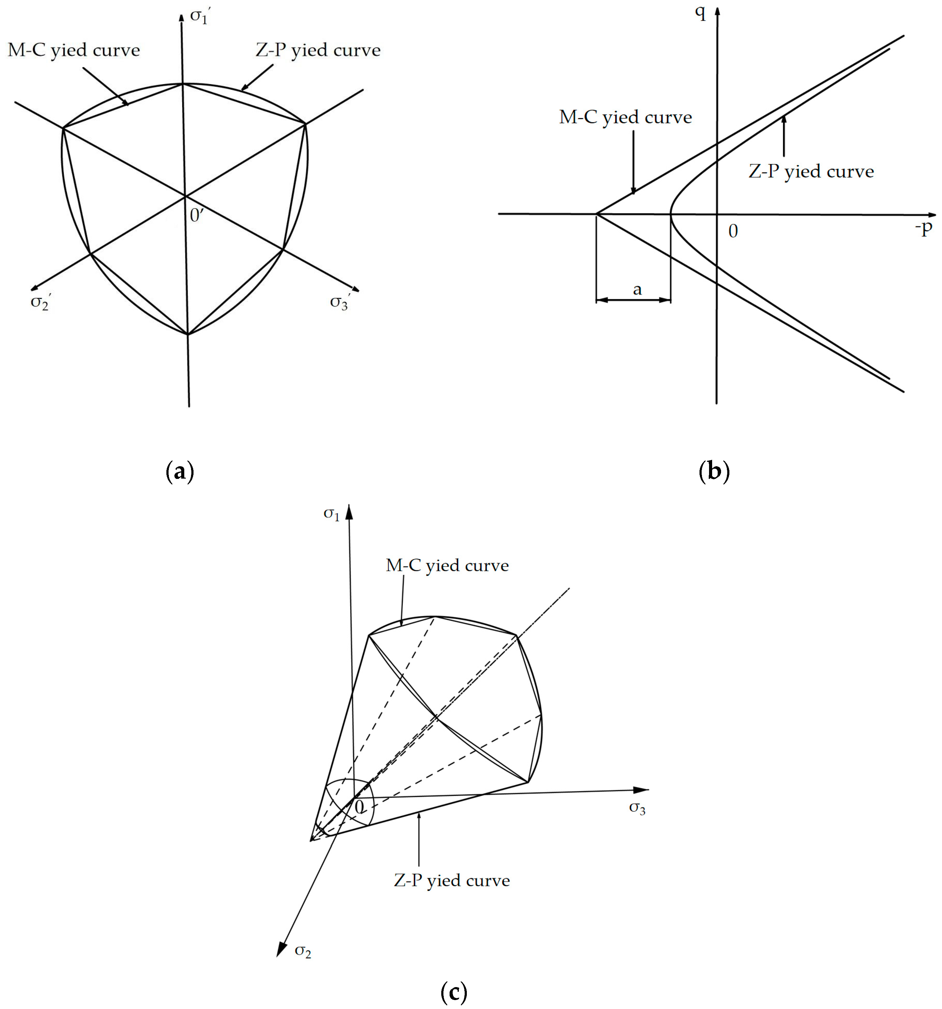
2. Z–P Yield Criterion

The Zienkiewicz–Pande yield criterion, also known as the Z–P yield criterion, was proposed by Zienkiewicz and Pande as an alternative to the Mohr–Coulomb yield criterion [29]. It was developed to address the limitations of the Mohr–Coulomb criterion, particularly when dealing with edges and sharp corners. The exact mathematical expression of the Z–P yield criterion can be described as follows:
f = β 2 p 2 + β 1 p γ + [ q g ( θ ) ] n = 0
where p = σ k k 3 , q = 1 2 s i j s i j , s i j = σ i j 1 3 σ k k δ i j , σij is the Cauchy stress and sij means the deviatoric Cauchy stress; β1 and β2 refer to coefficients; n is an exponent, generally 0, 1 or 2; γ is the yield parameter; g ( θ ) = 2 k ( 1 + k ) ( 1 k ) sin 3 θ is the shape function, k = 3 + sin φ 3 sin φ represents the ratio of triaxial tensile strength to triaxial compression strength; θ indicates the stress lode angle, and when θ = ± π 6 , the Z–P yield criterion is fitted with the M–C yield criterion.
This paper uses a branch of the hyperbola as the yield curve on the ε ¯ p = 2 3 ( ε ¯ p 1 ε ¯ p 2 ) 2 + ( ε ¯ p 1 ε ¯ p 3 ) 2 + ( ε ¯ p 2 ε ¯ p 3 ) 2 meridian plane. The Z–P yield criterion can therefore be depicted in the following form [30]:
f = tan φ ¯ p + q 2 g 2 ( θ ) + a 2 tan φ ¯ c ¯ = 0
where
tan φ ¯ = 6 sin φ 3 sin φ , c ¯ = 6 c sin φ 3 sin φ , sin 3 θ = 3 3 2 J 3 J 2 3
and φ represents the internal friction angle of the material, while c represents its cohesion. J2 and J3 correspond to the second and third invariants of the deviatoric stress tensor, respectively; a is a coefficient, and when it approaches 0, the yield curve is infinitely close to the M−C envelope.
The Z−P yield criterion addresses the issue of sharp corners and edges on the π plane and the p–q meridian plane encountered in the M−C yield criterion. Additionally, it takes into account the effects of hydrostatic pressure and intermediate principal stress, as well as the difference between the yield curve and the hydrostatic pressure (Figure 1).

3. Determination of Coupling Damage Variable

3.1. Mesoscopic Representation of High Temperature Damage Variable

Material damage is more intuitively considered as the proportion of internal defects in the physical sense, and the size of defects can serve as an indicator for assessing the decline in both physical and mechanical properties of materials at the mesoscopic level:
D = A e f f A = A A D A
D corresponds to the damage variable, which quantifies the extent of damage in the material. A represents the cross-sectional area of the undamaged material, while Aeff represents the effective cross-sectional area of the material considering the damage. AD refers to the damaged cross-sectional area of the material.
According to Lemaitre’s strain equivalence principle, the strain induced by the applied stress on the damaged material in the undamaged state is equivalent to the strain caused by equivalent stress acting on the undamaged material. This equivalence can be expressed using the high−temperature damage elastic modulus, Et. The high−temperature damage variable refers to a parameter that quantifies the extent of damage or degradation in a material under high−temperature conditions:
D t = 1 E t E

3.2. Load Damage Variable

The load-induced damage evolution process of rock was characterized and quantified using the concept of “equivalent plastic strain” in this study [31]:
ε ¯ p = 2 3 ( ε ¯ p 1 ε ¯ p 2 ) 2 + ( ε ¯ p 1 ε ¯ p 3 ) 2 + ( ε ¯ p 2 ε ¯ p 3 ) 2
D m = ( 1 β ) [ 1 exp ( ε ¯ p ε ¯ 0 p α ) ]
The principal plastic strains in three directions are denoted as ε ¯ p i (i = 1, 2, and 3), with ε ¯ 0 p = 0 indicating the threshold strain for load damage evolution; the value range of α is (0, ∞), which determines the initial slope of the rock’s softening curve after damage, and the value range of β is [0, 1], which determines the maximum damage value of the rock.
To further clarify the physical meanings of α and β, referring to the research of Parisio and Laloui [32], the parameter e = 1 − Dm was introduced. Then, the expression of e can be obtained from Equation (7):
e = 1 D m = β + ( 1 β ) exp ( ε ¯ p α )
The slope of e is the same as the slope of the softening section of the rock (softening rate), and the derivative of e can be obtained:
e ε ¯ p = 1 β α exp ( ε ¯ p α )
When ε ¯ p = 0 , there are
e ε ¯ p | ε ¯ p = 0 = 1 β α
Therefore, in the ( ε ¯ p , e) coordinate system, the equation of the straight line passing through the (0, 1) point (at ε ¯ p = 0 , the damage value is 0, and the parameter e = 1) can be written as
e = 1 β α ε ¯ p + 1
The point where this line intersects the ε ¯ p axis is
ε ¯ p = α 1 β
when β = 1, the damage value is always 0.
By selecting several representative values of α and β, the curve of damage evolution law was drawn as shown in Figure 2. It is evident that as α increased, the rate of damage evolution in the rock mass decreased. Similarly, as β increased, the final damage value of the rock mass decreased.

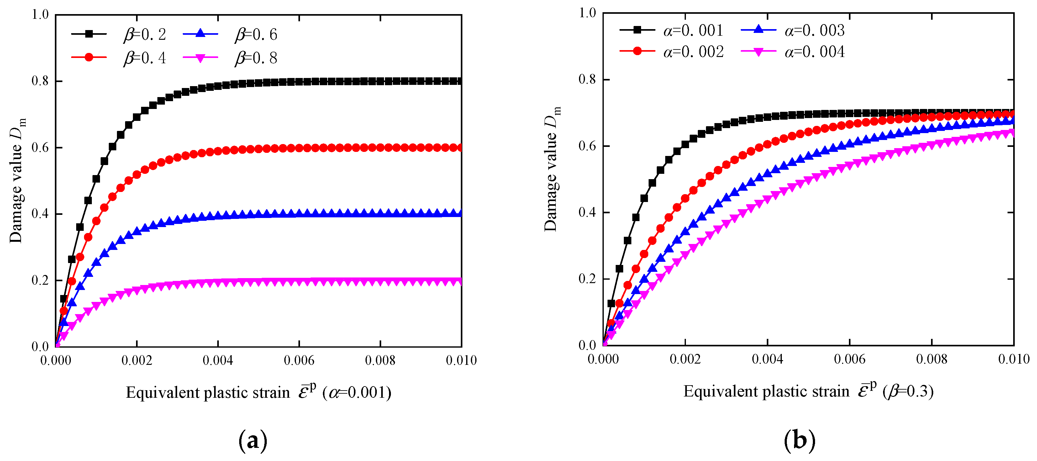
3.3. High-Temperature-Load Coupled Damage Variable

The damage on the same cross-section is composed of two components. If the damage Dt occurs first and is followed by the damage Dm, the coupled damage evolution process can be represented by the coupled damage variable Dc:
D c = D t + D m D t D m = ( 1 E t E ) + ( 1 β ) [ 1 exp ( ε ¯ p ε ¯ 0 p α ) ] ( 1 E t E ) ( 1 β ) [ 1 exp ( ε ¯ p ε ¯ 0 p α ) ]

4. Elastoplastic Damage Constitutive Model Considering High-Temperature Damage

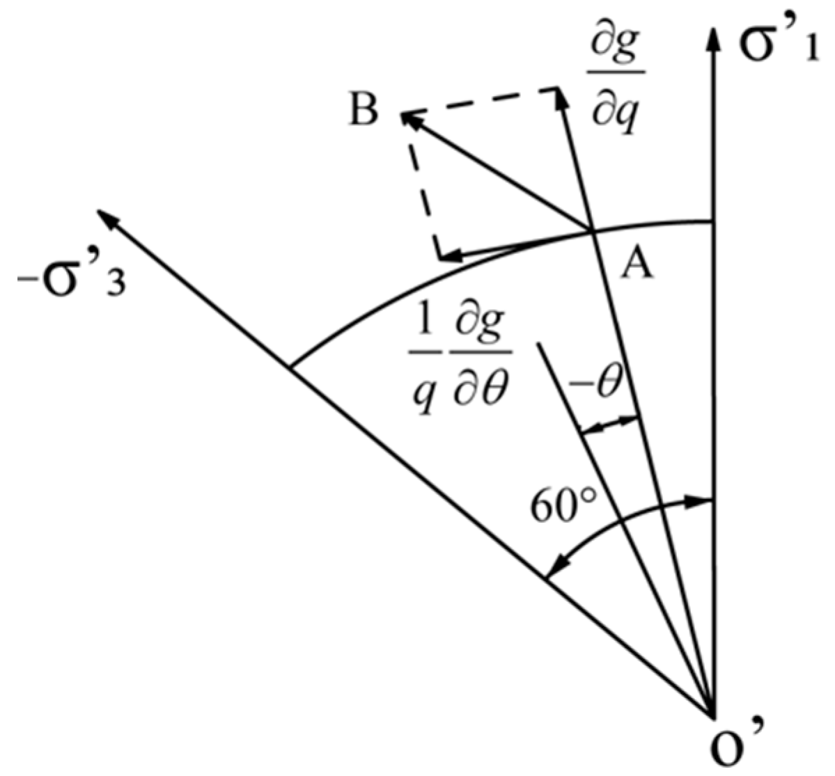
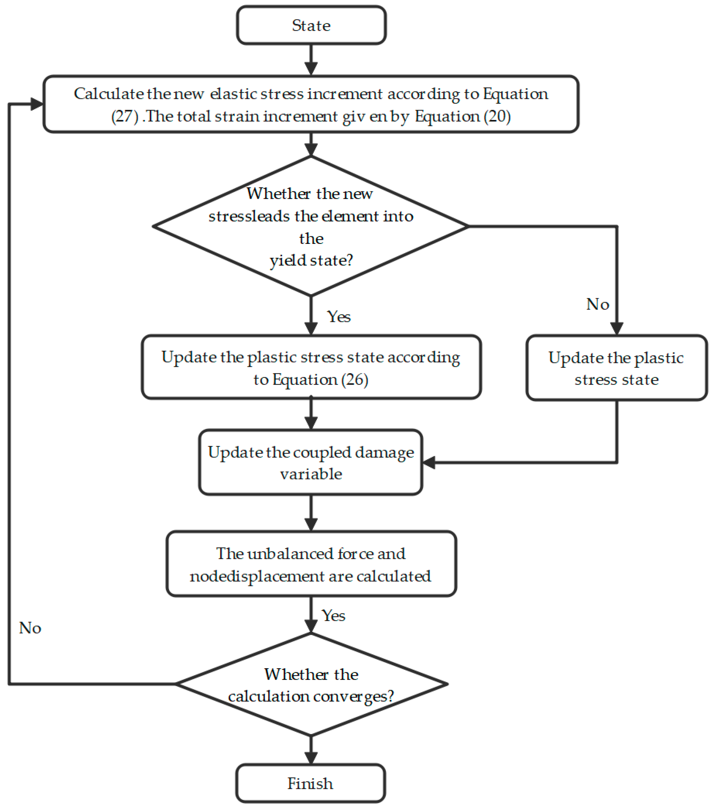
4.1. Incremental Iterative Algorithm for Z–P Damage Constitutive Model

The FLAC3D 5.0 software is applicable for numerical analysis that utilizes a three-dimensional explicit finite difference approach. This algorithm provides accurate simulation of the yield, plastic flow, softening, and large deformation behavior of geotechnical materials, particularly in elastoplastic analysis and analysis of materials undergoing significant deformation, and has unique advantages. Meanwhile, the simple process control language and modular design of FLAC3D provide users with a convenient secondary development interface, which enables users to develop corresponding calculation models as necessary and embed self-defined constitutive models into FLAC3D.
All constitutive models in FLAC3D basically follow the same algorithm. Specifically, by substituting parameters such as the stress state at a given time t and the strain increment at the Δt time step into the corresponding constitutive equation in FLAC3D, the stress increment and stress state at time t + Δt can be obtained. If all the deformations that occur are elastic, the stress increment can be directly derived from it, but if plastic strain occurs, the assumed stress increment must be corrected to obtain a new stress increment and stress state. According to the incremental numerical algorithm in Flac3D [33], this section presents the incremental iterative scheme for the high-temperature-load coupled damage elastoplastic constitutive model, which is based on the Z–P yield criterion.
The Z–P yield criterion is written in the following form after introduction of coupling damage:
f = tan φ ¯ p + q g ( θ ) ( 1 D c ) c ¯ = 0
The plastic potential function using uncorrelated flow can be expressed as
g = tan ψ ¯ p + q g * ( θ ) ( 1 D c ) c * ¯ = 0
where tan ψ ¯ , g*(θ), c * ¯ are obtained by replacing internal friction angle φ in the expressions of tan φ ¯ , g(θ), c ¯ with expansion angle ψ, respectively.
The generalized strain increment Δε corresponding to p and q consists of two parts: the shear strain increment Δ γ and the volumetric strain increment Δεv:
Δ γ = 2 Δ e i j Δ e i j , Δ ε v = Δ ε k k
where Δ e i j = Δ ε i j Δ ε k k 3 denotes the deviatoric strain increment.
The Hooke’s law equation, relating the elastic shear strain increment and the elastic volumetric strain increment, can be described as follows:
Δ q = G ( D c ) Δ γ e , Δ p = K ( D c ) Δ ε v e
The non-destructive shear modulus G0 and bulk modulus K0 can be employed to express the damage shear modulus G(Dc) and bulk modulus K(Dc):
G ( D c ) = ( 1 D c ) G 0 , K ( D c ) = ( 1 D c ) K 0
According to the plastic flow law, when considering shear failure, the increase in plastic shear strain Δγp and the increase in plastic volumetric strain Δεvp can be expressed as
Δ γ p = λ g q = λ g * ( θ ) , Δ ε v p = λ g p = λ tan ψ ¯
where λ is the plastic factor.
Since the plastic potential function of the Z–P yield criterion is influenced by the Lode angle, the flow direction of shear plastic strain on the deviated plane should be along the AB direction, as displayed in Figure 3. The elastic shear strain increment Δγp expression in Equation (19) can be rewritten as
Δ γ p = λ ( ( g q ) 2 + ( 1 q g θ ) 2 ) = λ g * 2 ( θ ) + g * 2 ( θ ) g * 2 ( θ )
After defining the stress states at time t + Δt as pN and qN and the corresponding elastic predicted stress states as pI and qI, Δγp and Δεvp in the above formula can be used to replace Δγe, Δεve in Equation (17). Then, we have:
q N = q I G ( D c ) λ g * 2 ( θ ) + g * 2 ( θ ) g * 2 ( θ ) , P N = P I K ( D c ) λ tan ψ ¯
where
λ = tan φ ¯ p I + q I g ( θ ) ( 1 D c ) c ¯ K ( D c ) tan ψ ¯ tan φ ¯ + G ( D c ) g * 2 ( θ ) + g * 2 ( θ ) g * 2 ( θ ) g ( θ )
We rewrite qN in Equation (21) into the following form:
q N = μ q I , μ = 1 G ( D c ) λ g * 2 ( θ ) + g * 2 ( θ ) q I g * 2 ( θ )
From the definition of q, we can obtain
s i j N = μ s i j I
and eliminate μ:
s i j N = s i j I q N q I
Finally, the new stress component formula can be obtained:
σ i j N = s i j N + p N δ i j

4.2. Z–P Secondary Development Process of Damage Constitutive Model

The process of secondary development of the constitutive model consists of three parts: modifying the header file (.h file), modifying the program file (.cpp file), and generating the dynamic link library file (.dll file). Modifications of header and program files include modifications to base class descriptions, modifications to member functions, modifications to model registration, modifications to information transfer between the model and FLAC3D, and modifications to model state indicators [34].
The .dll file was compiled with Microsoft Visual Studio 2010. The model needed to be configured for use by the Model Configure Plugin command before assigning the constitutive model to the computational model. In terms of elastoplastic numerical calculation, the element yields can be judged based on the specific expression of the yield function and the stress state of the element. When f 0 , the element yields; when f < 0 , the element remains elastic. For elements in an elastic state, the elastic constitutive model was adopted during iteration
Δ σ 1 = α 1 Δ ε 1 e + α 2 ( Δ ε 2 e + Δ ε 3 e ) Δ σ 2 = α 1 Δ ε 2 e + α 2 ( Δ ε 1 e + Δ ε 3 e ) Δ σ 3 = α 1 Δ ε 3 e + α 2 ( Δ ε 1 e + Δ ε 2 e )
where Δσi means the main stress component increment; Δεie is the main strain elastic component increment (i = 1, 2 and 3); α1 and α2 indicate elastic constants of the material, which are determined by the bulk deformation modulus K and the shear deformation modulus G and its expression can be expressed as follows:
α 1 = K ( D t ) + 4 3 G ( D t ) α 2 = K ( D t ) 2 3 G ( D t )
For elements entering the plastic state, the plastic flow law should be used for correction and calculation, that is, Equation (26). The program flowchart is shown in Figure 4.

5. Model Verification

5.1. Program Correctness Verification

Without considering the damage, as for the shape function g ( θ ) = 3 sin φ 2 ( 3 cos θ sin θ sin φ ) of the Z–P constitutive model proposed in this paper, the model degenerated into the Mohr–Coulomb constitutive model. By rewriting the program to adjust the shape function, the simulation calculation of an ideal circular tunnel was carried out. The results of the established Mohr–Coulomb constitutive model in Flac3D were further compared to verify the correctness and accuracy of the model’s secondary development program described in this paper. Figure 5 shows the selected calculation model, with the tunnel excavation radius of 1.0 m, the boundary of 10 m away from the center of the tunnel, and the applied stress of 30 MPa. Moreover, the simulation parameters were set accordingly, including the bulk modulus K of 3.9 GPa, the shear modulus G of 2.8 GPa, the cohesion c of 3.45 MPa, and the internal friction angle φ of 30°. The correlation flow method was utilized for computation. Figure 6 summarizes the calculation results.
From Figure 6, it is evident that the calculation results of the two were practically in agreement. The average relative error of the calculated hoop stress was 0.485% and the average percentage error of the radial stress was 1.246%, which satisfied the accuracy requirements, further proving the correctness of the secondary development program used in this paper. Compared to the M–C constitutive model, except for the basically same elastic region, the Z–P constitutive model had a higher stress value at the elastic–plastic interface and a smaller radius at the plastic region. Both were confirmed to share the same elastic space. The Z–P constitutive model took into account the influence of the intermediate principal stress on the strengthening effect of rock strength [35,36].
In addition, when the shape function was g(θ) = 1, the model degenerated into a Drucker–Prager constitutive model in the form of a circumscribed circle, and the two would not be compared in this paper.

5.2. Example Verification

To validate the rationality of the proposed elastic–plastic constitutive model for high-temperature-load coupled damage, numerical simulations were conducted to compare the results with the uniaxial experimental data of granite under different high-temperature conditions, as reported by Luo et al. and Zhang et al. [37,38]. Two sets of experimental data were used for the comparison. The experimental granite was obtained by collecting on-site rock samples from local granite outcrops in the Gonghe Basin, based on the rock characteristics of the dry hot rock target area. X-ray diffraction composition analysis determined that the mineral contents of quartz, sodium feldase and mica were 10.96%, 81.65% and 7.39%, respectively. Before high-temperature treatment, the density and longitudinal wave velocity of each sample were determined, and the samples with abnormal density and wave velocity were removed to ensure the reliability and comparability of the test results. The average density of the samples used was 2.492 g/cm3, and the average longitudinal wave velocity was 4176 m/s [37]. For the granite rock samples in the referenced paper with a dense structure and no obvious cracks, before high-temperature treatment, the density and longitudinal wave velocity of each sample were measured, and samples with abnormal density and wave velocity were removed. The test results were proved to be reliable and comparable. Numerical simulation parameters were selected as follows: Poisson’s ratio μ = 0.35, and density ρ = 2492 kg/m3 for the first set; Poisson’s ratio μ = 0.32, and density ρ = 2260 kg/m3 for the second set. Because of little influence of damage on the internal friction angle, the internal friction angle and the expansion angle were set as constants, with φ = 48°, and ψ = 40°, respectively [38]. Other parameters are organized in Table 1 and Table 2. The selection of numerical simulation parameters included Poisson’s ratio, density, internal friction angle, dilation angle, elastic modulus, cohesive strength, and thermal damage parameters α and β. Poisson’s ratio, internal friction angle, elastic modulus, and cohesive strength were obtained through rock triaxial compression tests. Density was calculated based on the relationship between mass and volume. The dilation angle was determined by applying confining pressure and measuring the change in sample volume. Generally, all of these parameters could be obtained through laboratory rock testing. The thermal damage parameters α and β were acquired by fitting experimental curves.
The numerical simulation results were compared to the experimental data in the literature, as presented in Figure 7 and Figure 8. Since this model did not account for the deformation characteristics during the compaction stage, a certain level of deviation from the stress–strain curve was observed in tests. Comparing the elastic stage before the two peaks, as depicted in Figure 9, the error of peak stress and peak strain was less than 6.5%, and the temperature-dependent variation trends of peak stress and peak strain also verified the weakening effect of high temperature on rock strength again. After transitioning to the post-peak plastic deformation stage, the accumulation of damage caused a significant decline in the specimen’s strength, and the stress–strain curve obtained from numerical simulation after reaching its peak displayed a similar trend compared with the experimental results. To sum up, it was demonstrated that the proposed elastic–plastic constitutive model considering high-temperature-load coupled damage in this paper was reasonable. According to the calculation results of the model, it was recommended to choose the value range of α for thermal damage parameters as (0.001, 0.01), and the value range of β as [0.1, 0.5].

6. Conclusions

To describe the mechanical behavior of rocks under high temperature more accurately, based on the Zienkiewicz–Pande yield criterion, a secondary development was carried out on the Flac3D 5.0 software by introducing the high-temperature-load coupled damage variable Dc. The research results are as follows:
  • Based on the Zienkiewicz–Pande yield criterion, by introducing the damage variable Dc coupled with high-temperature and mechanical load, and according to the incremental numerical algorithm in Flac3D, the detailed derivation of the augmented elastic–plastic constitutive model for high-temperature-load coupled damage was presented. The quantitative iterative equation and the calculation process were developed by virtue of Visual Studio C++ and compiled into the corresponding dynamic link library file, which was successfully applied in numerical simulation of rocks using Flac3D software.
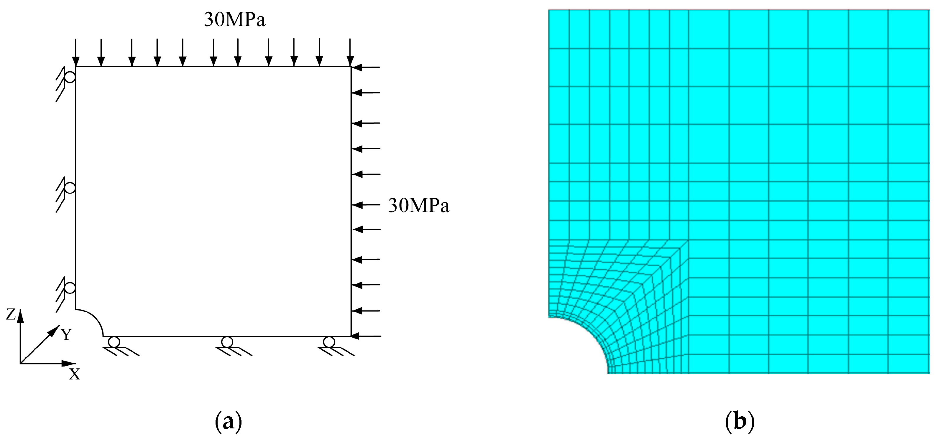
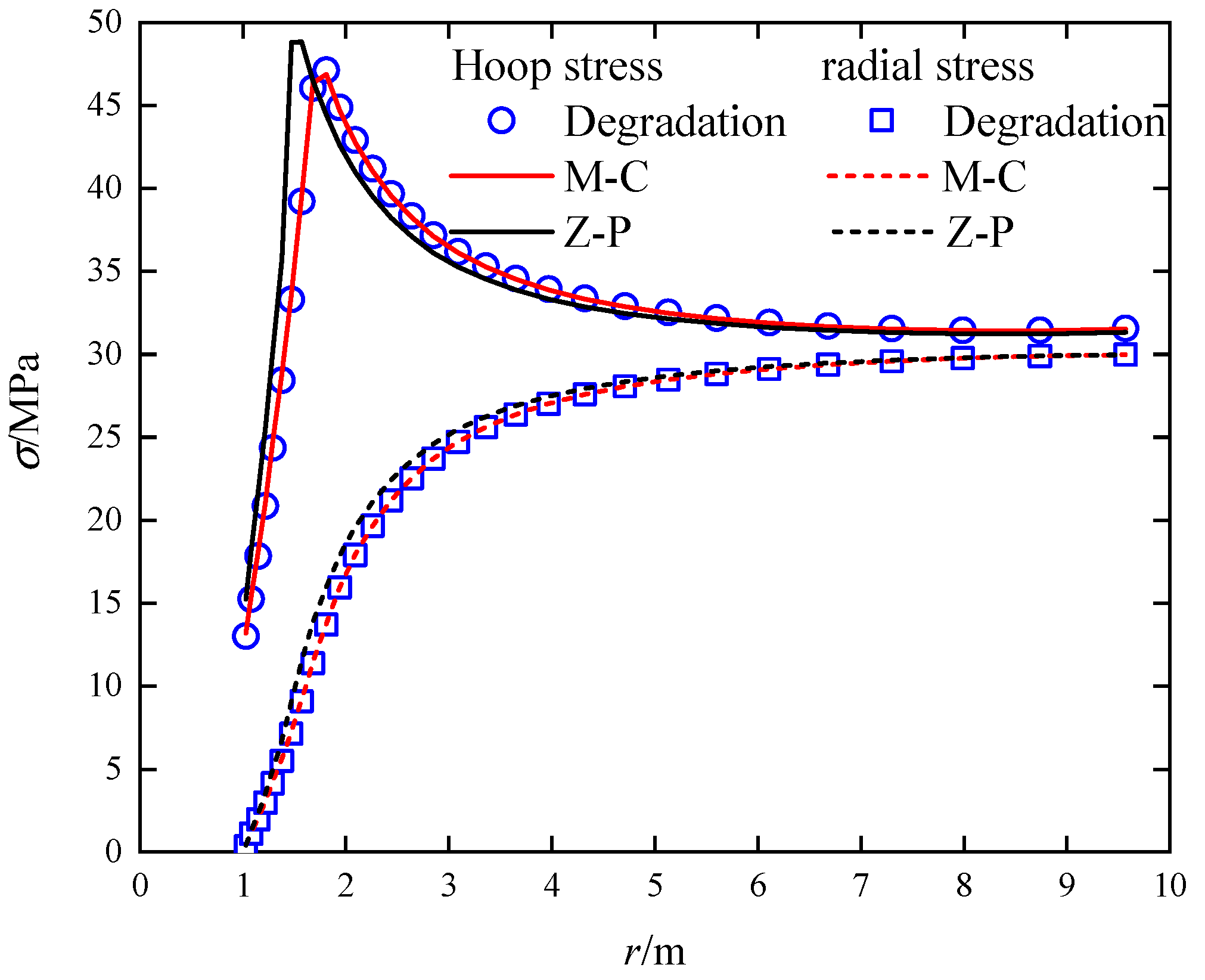
  • By adjusting the shape function, the Z–P constitutive model degenerated into an M–C constitutive model. The simulation results of an ideal circular tunnel using Flac3D manifested that the calculation results of the degenerated Z–P constitutive model were similar to those of the M–C constitutive model built in Flac3D. Compared to the computed outcomes of the model, the average relative error of the hoop stress was 0.485%, and the radial stress appeared an average relative error of 1.246%, which conformed to the accuracy requirements and verified the correctness of the secondary development program.
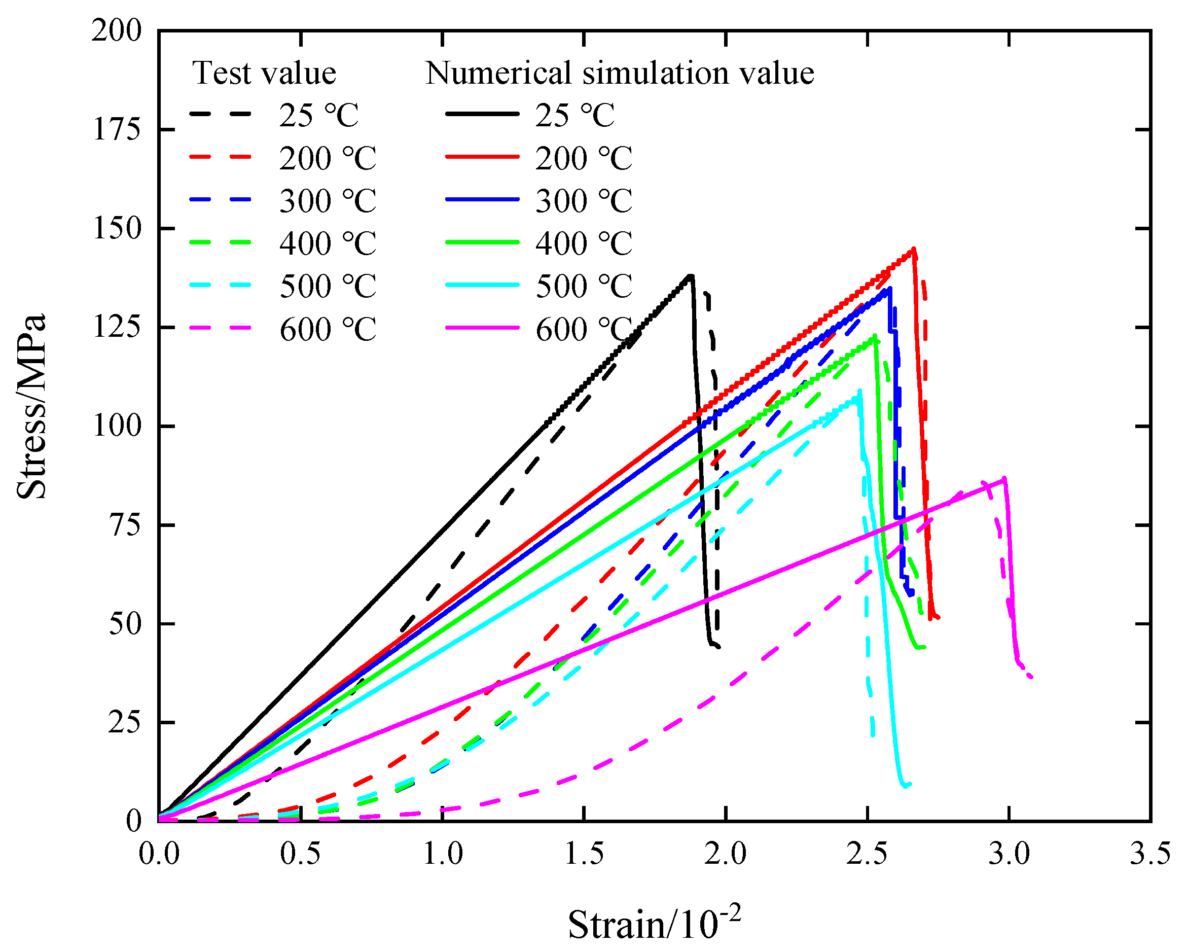
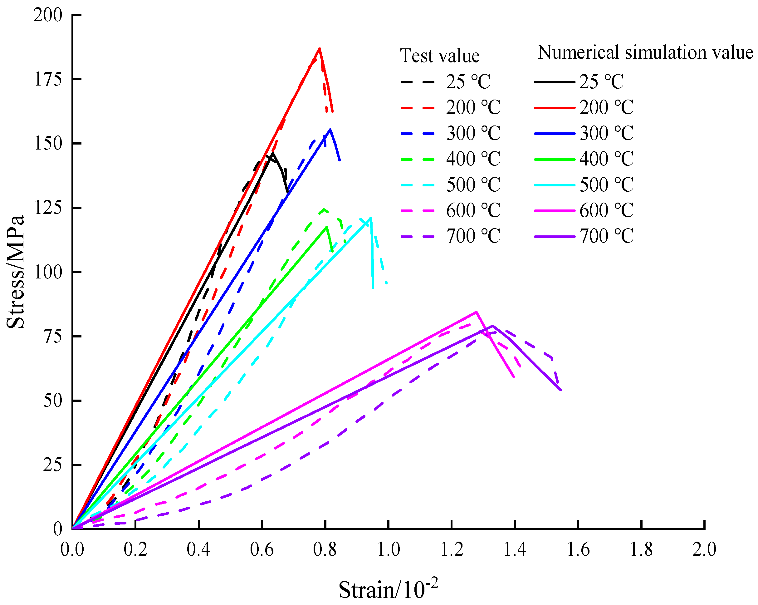
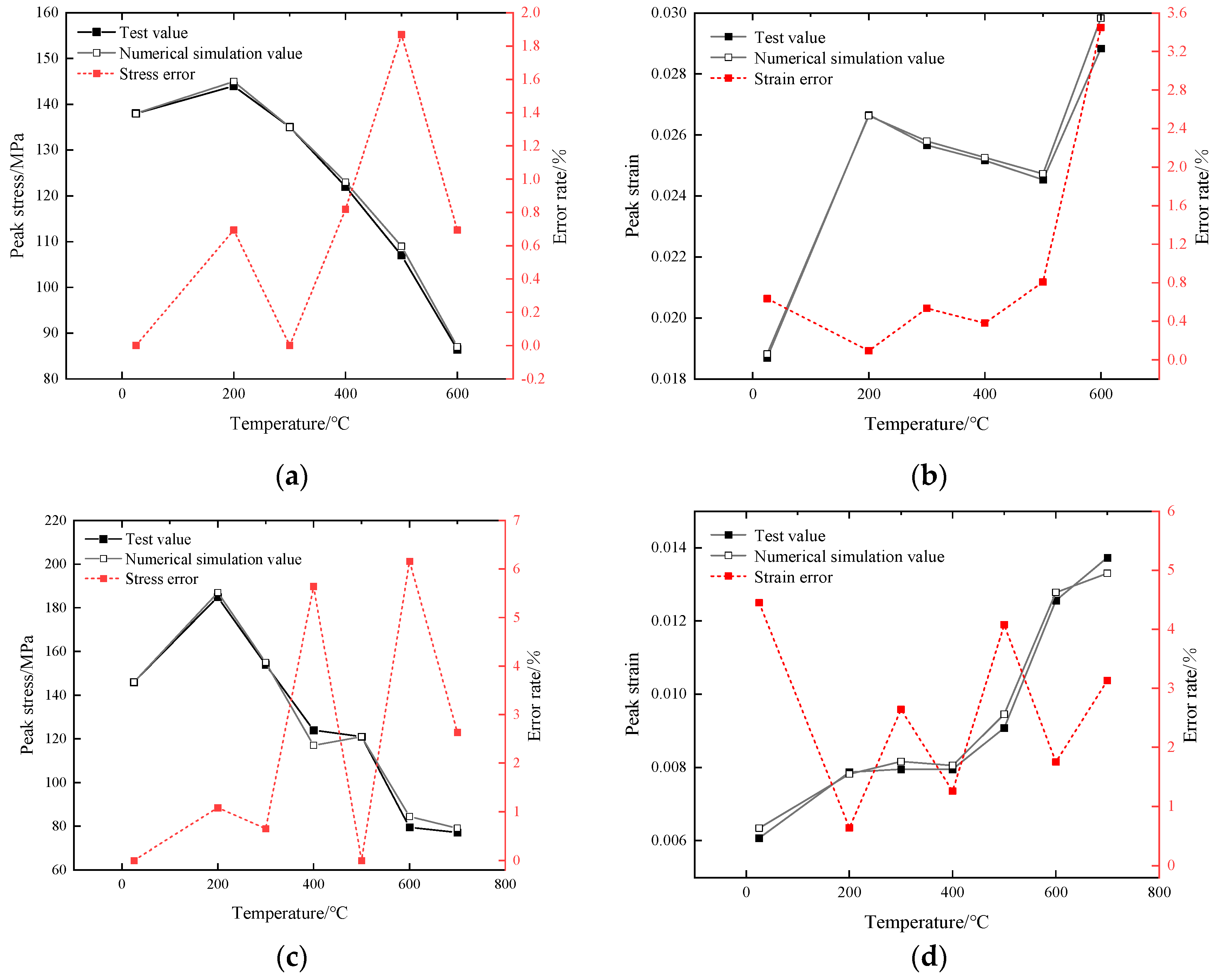
  • Through conducting uniaxial compression test simulations on granite at various high temperatures, the obtained stress–strain curves in the numerical simulation were compared with experimental data from the existing literature. The comparison revealed a similar trend between the numerical simulation and test results under different high temperatures. Additionally, the discrepancy between the peak stress and peak strain values was found to be within 6.5%. This outcome validated the rationality of the proposed high-temperature-load coupled damage model based on the Zienkiewicz–Pande yield criterion, and demonstrated its ability to accurately depict the mechanical behavior of rocks subjected to high-temperature treatment. Furthermore, it was recommended to choose the value range of α for thermal damage parameters as (0.001, 0.01), and the value range of β as [0.1, 0.5].

7. Outlook

  • It is expected to further expand and deepen the research on the model by increasing the sample size, including a wider range of rock samples with different types and characteristics, to comprehensively validate the applicability and accuracy of the model. Additionally, more extensive experiments and numerical simulations covering a broader range of temperature, stress, and loading conditions are necessary to precisely understand both thermodynamic and mechanical responses of rocks.
  • In terms of engineering applications, the model can be applied in practical engineering projects. By integrating the model with real-world engineering cases, the predictive capability and applicability of the model in actual engineering environments can be evaluated. Such application assessments contribute to validating the reliability of the model and providing guidance and decision support for engineers.

Author Contributions

Conceptualization, T.Z. and F.Z.; methodology, F.Z.; software, T.Z.; validation, T.J.; formal analysis, F.Z.; investigation, T.Z., T.J. and S.S.; resources, A.J., T.Z. and S.S.; data curation, X.G., T.J. and F.Z.; writing—original draft preparation, A.J. and X.G.; writing—review and editing, A.J.; visualization, F.Z.; supervision, S.S.; project administration, F.Z.; funding acquisition, A.J. All authors have read and agreed to the published version of the manuscript.

Funding

This research was funded by the National Natural Science Foundation of China, grant number 52078093, LiaoNing Revitalization Talents Program, grant number XLYC1905015, Cultivation Program for the Excellent Doctoral Dissertation of Dalian Maritime University, grant number 2022YBPY009, Jiangxi Province High Level and Skilled Leading Talent Training Project Candidate Project.

Institutional Review Board Statement

Not applicable.

Informed Consent Statement

Informed consent was obtained from all subjects involved in the study.

Data Availability Statement

Data sharing not applicable.

Conflicts of Interest

The authors declare no conflict of interest.

References

  1. Wasantha, P.L.P.; Guerrieri, M.; Xu, T. Effects of tunnel fires on the mechanical behaviour of rocks in the vicinity—A review. Tunn. Undergr. Space Technol. 2020, 108, 103667. [Google Scholar] [CrossRef]
  2. Leroy, M.N.L.; Marius, F.W.; François, N. Experimental and Theoretical Investigations of Hard Rocks at High Temperature: Applications in Civil Engineering. Adv. Civ. Eng. 2021, 2021, 8893944. [Google Scholar] [CrossRef]
  3. Savov, K.; Lackner, R.; Mang, H.A. Stability assessment of shallow tunnels subjected to fire load. Fire Saf. J. 2005, 40, 745–763. [Google Scholar] [CrossRef]
  4. Healy, J.; Atefi-Monfared, K. Fire-induced damage in tunnels: Thermo-mechanical modeling incorporating support system and geological conditions. Tunn. Undergr. Space Technol. 2023, 135, 105027. [Google Scholar] [CrossRef]
  5. Lu, C.; Sun, Q.; Zhang, W.Q.; Geng, J.S.; Qi, Y.M.; Lu, L.L. The effect of high temperature on tensile strength of sandstone. Appl. Therm. Eng. 2017, 111, 573–579. [Google Scholar] [CrossRef]
  6. Xi, Y.; Wang, H.Y.; Li, J.; Dong, W.T.; Li, H.; Guo, B.Y. Experimental comparison of mechanical properties and fractal characteristics of geothermal reservoir rocks after different cooling treatments. Energy Rep. 2022, 8, 5158–5176. [Google Scholar] [CrossRef]
  7. Huang, Y.-H.; Yang, S.-Q.; Tian, W.-L.; Zhao, J.; Ma, D.; Zhang, C.-S. Physical and mechanical behavior of granite containing pre-existing holes after high temperature treatment. Arch. Civ. Mech. Eng. 2017, 17, 912–925. [Google Scholar] [CrossRef]
  8. Wang, Z.; Zhang, W.; Shi, Z.; Zhang, S. Changes of physical properties of thermal damaged sandstone with time lapse. Acta Geophys. 2022, 70, 1193–1202. [Google Scholar] [CrossRef]
  9. Zhang, H.M.; Qin, X.R.; Chen, M.; Yang, G.S.; Lu, Y.N. A Damage Constitutive Model for a Jointed Rock Mass under Triaxial Compression. Int. J. Geomech. 2023, 23, 04023059. [Google Scholar] [CrossRef]
  10. Mortazavi, A.; Molladavoodi, H. A numerical investigation of brittle rock damage model in deep underground openings. Eng. Fract. Mech. 2012, 90, 101–120. [Google Scholar] [CrossRef]
  11. Jiang, Q.; Feng, X.T.; Zhou, H.; Chen, J.L.; Wan, X.B. In situ damage testing of rock mass in large underground cavern. Mater. Res. Innov. 2011, 15, s531–s535. [Google Scholar] [CrossRef]
  12. Jiang, Q.; Cui, J.; Chen, J. Time-Dependent Damage Investigation of Rock Mass in an In Situ Experimental Tunnel. Materials 2012, 5, 1389–1403. [Google Scholar] [CrossRef]
  13. Hu, J.-H.; Yang, D.-J. Meso-damage evolution and mechanical characteristics of low-porosity sedimentary rocks under uniaxial compression. Trans. Nonferrous Met. Soc. China 2020, 30, 1071–1077. [Google Scholar] [CrossRef]
  14. Liu, B.X.; Shu, Z.L.; Liu, M.M.; Zhang, K. Real-time CT Experimental Research on Microscopic Damage Evolution of Coal Rock under Compression. Disaster Adv. 2012, 5, 164–172. [Google Scholar]
  15. Qi, X.Y.; Yang, Z.; Wang, S.W.; Fu, P. Mechanical Damage Test and Model Study of Layered Composite Rock Based on Acoustic Emission and DIC Characteristics. Shock Vib. 2022, 2022, 6568588. [Google Scholar] [CrossRef]
  16. Wang, C.L.; He, B.B.; Hou, X.L.; Li, J.Y.; Liu, L. Stress-Energy Mechanism for Rock Failure Evolution Based on Damage Mechanics in Hard Rock. Rock Mech. Rock Eng. 2020, 53, 1021–1037. [Google Scholar] [CrossRef]
  17. Zhang, Z.P.; Zhang, R.; Xie, H.P.; Liu, J.F.; Were, P. Differences in the acoustic emission characteristics of rock salt compared with granite and marble during the damage evolution process. Environ. Earth Sci. 2015, 73, 6987–6999. [Google Scholar] [CrossRef]
  18. Ahmed, Z.; Wang, S.H.; Hashmi, M.Z.; Zhang, Z.; Zhu, C. Causes, characterization, damage models, and constitutive modes for rock damage analysis: A review. Arab. J. Geosci. 2020, 13, 806. [Google Scholar] [CrossRef]
  19. Wen, T.; Tang, H.; Ma, J.; Liu, Y. Energy Analysis of the Deformation and Failure Process of Sandstone and Damage Constitutive Model. KSCE J. Civ. Eng. 2019, 23, 513–524. [Google Scholar] [CrossRef]
  20. Liu, W.; Zhang, S.; Sun, B. Energy Evolution of Rock under Different Stress Paths and Establishment of A Statistical Damage Model. KSCE J. Civ. Eng. 2019, 23, 4274–4287. [Google Scholar] [CrossRef]
  21. Ma, S.; Gutierrez, M. Coupled Damage-Plasticity Modelling of Saturated Shale under Undrained Condition. KSCE J. Civ. Eng. 2021, 25, 316–325. [Google Scholar] [CrossRef]
  22. Zhu, Y. A micromechanics-based damage constitutive model of porous rocks. Int. J. Rock Mech. Min. Sci. 2017, 91, 1–6. [Google Scholar] [CrossRef]
  23. Yang, J.; Fu, L.-Y.; Zhang, Y.; Han, T. Temperature- and Pressure-Dependent Pore Microstructures Using Static and Dynamic Moduli and Their Correlation. Rock Mech. Rock Eng. 2022, 55, 4073–4092. [Google Scholar] [CrossRef]
  24. Guo, X.; Zhang, D.; Zhao, C.; Zhang, X.; Wang, M.; Zhu, Y. Constitutive theory and thermodynamic framework for hyperplastic damage of deep rock structure. Chin. J. Rock Mech. Eng. 2016, 35, 658–669. (In Chinese) [Google Scholar] [CrossRef]
  25. Peng, J.; Tang, Z.C.; Hou, D. A GSI-softening model for characterizing strength behavior of thermally-damaged rock. Eng. Geol. 2021, 292, 106251. [Google Scholar] [CrossRef]
  26. Xu, X.L.; Karakus, M. A coupled thermo-mechanical damage model for granite. Int. J. Rock Mech. Min. Sci. 2018, 103, 195–204. [Google Scholar] [CrossRef]
  27. Mercado, V.; Fuentes, W.; Ochoa-Cornejo, F. Multiyield-Surface Implementation of a Simplified Three-Dimensional Hoek–Brown Strength Criterion. Int. J. Geomech. 2022, 22, 06021039. [Google Scholar] [CrossRef]
  28. Cuss, R.J.; Rutter, E.H.; Holloway, R.F. The application of critical state soil mechanics to the mechanical behaviour of porous sandstones. Int. J. Rock Mech. Min. Sci. 2003, 40, 847–862. [Google Scholar] [CrossRef]
  29. Zienkiewicz, O.C.; Pande, G.N. Some useful forms of isotropic yield surfaces for soil and rock mechanics. In Finite Elements in Geomechanics; John Wiley & Sons: New York, NY, USA, 1977; pp. 179–190. [Google Scholar]
  30. Liu, Y.; Maniatty, A.M.; Antes, H. Investigation of a Zienkiewicz–Pande yield surface and an elastic–viscoplastic boundary element formulation. Eng. Anal. Bound. Elem. 2000, 24, 207–211. [Google Scholar] [CrossRef]
  31. Asgari, M.; Kouchakzadeh, M.A. An equivalent von Mises stress and corresponding equivalent plastic strain for elastic–plastic ordinary peridynamics. Meccanica 2019, 54, 1001–1014. [Google Scholar] [CrossRef]
  32. Parisio, F.; Laloui, L. Plastic-damage modeling of saturated quasi-brittle shales. Int. J. Rock Mech. Min. Sci. 2017, 93, 295–306. [Google Scholar] [CrossRef]
  33. Zhang, C.; Zhou, H.; Feng, X. Numerical format of elastoplastic constitutive model based on the unified strength theory in FLAC3D. Rock Soil Mech. 2008, 3, 596–602. [Google Scholar] [CrossRef]
  34. He, Z.; Dai, B. Secondary Development of a Nonlinear Creep Model Based on Fractional Derivative in FLAC3D. In Proceedings of the 11th International Conference on Intelligent Computation Technology and Automation (ICICTA), Changsha, China, 22–23 September 2018. [Google Scholar] [CrossRef]
  35. Li, A.; Shao, G.J.; Li, Y.D.; Sun, Y.; Su, J.B.; Liu, J.C. Investigation Into Deformation and Failure Characteristics of the Soft-Hard Interbedded Rock Mass Under Multiaxial Compression. Front. Earth Sci. 2022, 10, 903743. [Google Scholar] [CrossRef]
  36. Trzeciak, M.; Sone, H. Critical review of the Mogi failure criterion based on true-triaxial laboratory data analysis and theoretical considerations. Int. J. Rock Mech. Min. Sci. 2022, 159, 105220. [Google Scholar] [CrossRef]
  37. Luo, S.; Dou, B.; Tian, H.; Chen, J.; Xiao, P.; Zhang, S. Comparative experimental study on physical and mechanical properties of granite after natural cooling and under real-time high temperature. Earth Sci. Front. 2020, 27, 178–184. (In Chinese) [Google Scholar] [CrossRef]
  38. Jiang, H.; Jiang, A.; Xu, M. Research on Algorithm and Coupling Damage Model of Rock Under High Temperature and Loading Based on Mohr–Coulomb Criterion. Int. J. Comput. Methods 2022, 19, 2250001. [Google Scholar] [CrossRef]
Figure 1. Yield curve (surface) on π plane, p−q meridian plane, and principal stress space of Z−P constitutive model: (a) π plane; (b) p−q meridian plane; (c) principal stress space.
Applsci 13 09786 g001
Figure 2. Influence of damage parameters on damage evolution law: (a) Influence of β on damage evolution law (α = 0.001); (b) Influence of α on damage evolution law (β = 0.3).
Applsci 13 09786 g002
Figure 3. Plastic flow of shear strain in the partial plane.
Applsci 13 09786 g003
Figure 4. The program flow chart of the Z–P damage constitutive model.
Applsci 13 09786 g004
Figure 5. Calculation model of ideal circular tunnel: (a) Constraints of computational models; (b) Calculation model.
Applsci 13 09786 g005
Figure 6. Comparison of stress distribution between the Z–P constitutive model and the M–C constitutive model.
Applsci 13 09786 g006
Figure 7. Comparison between test curve and model calculation curve under different temperatures in the first set.
Applsci 13 09786 g007
Figure 8. Comparison between test curve and model calculation curve under different temperatures in the second set.
Applsci 13 09786 g008
Figure 9. Comparison of stress and strain peak values between test and model at different temperatures: (a) The first set of stress peak value and error; (b) The first set of strain peak value and error; (c) The second set of stress peak value and error; (d) The second set of strain peak value and error.
Applsci 13 09786 g009
Table 1. The relevant parameters for the numerical simulation of the first set.
Temperature/°CE/GPac/MPaαβ
257.8260.003390.17614
2008.0280.002540.31779
3007.6260.002470.40011
4007.2230.001770.39307
5006.8210.002380.15821
6005.8170.001300.38122
Table 2. The relevant parameters for the numerical simulation of the second set.
Temperature/°CE/GPac/MPaαβ
2527.9310.005470.39548
20028.5360.005020.43214
30024.5290.003770.41240
40020.1260.003100.37546
50016.8220.002480.39462
6008.3170.001540.21541
7008.5180.001690.18468
Disclaimer/Publisher’s Note: The statements, opinions and data contained in all publications are solely those of the individual author(s) and contributor(s) and not of MDPI and/or the editor(s). MDPI and/or the editor(s) disclaim responsibility for any injury to people or property resulting from any ideas, methods, instructions or products referred to in the content.

