Abstract
The good sealing caprocks are significant for the integrity of underground gas storage (UGS) in depleted natural gas reservoirs. The screening of parameters, weight assignment, and evaluation method are important for evaluating the sealing performance of caprocks. Many factors can affect the sealing performance of caprocks, including caprock thickness, lithology, brittleness, porosity and permeability, breakthrough pressure, etc. In this paper, the dominant factors in the sealing performance of caprocks in UGSs are systematically analyzed, and the weights of these factors are analyzed by the analytic hierarchy process (AHP). The fuzzy comprehensive evaluation method (FCEM) is applied in the sealing evaluation of caprocks in three typical underground gas reservoirs (i.e., Zhujiadun, Xu-2, and Xing-9) in China. The sandstone reservoir in the Zhujiadun gas field is only about 20 m, and the thickness of the overlying mudstone is about 600 m. The caprock of the Xu-2 gas reservoir in Zhongba gas field is well distributed and developed, and the breakthrough pressure is relatively large. The caprock of Xing-9 gas field is mudstone with a thickness of over 400 m. The results show that the breakthrough pressure and permeability are the key parameters affecting the sealing ability of caprocks, with weights of 0.4291 and 0.2157, respectively. Among these three examples of gas fields, the sealing performance of caprocks in Zhujiadun gas storage is the best. The evaluation procedure and methods proposed in this paper are valuable for the evaluation of the tightness of caprocks in depleted gas reservoirs.
1. Introduction
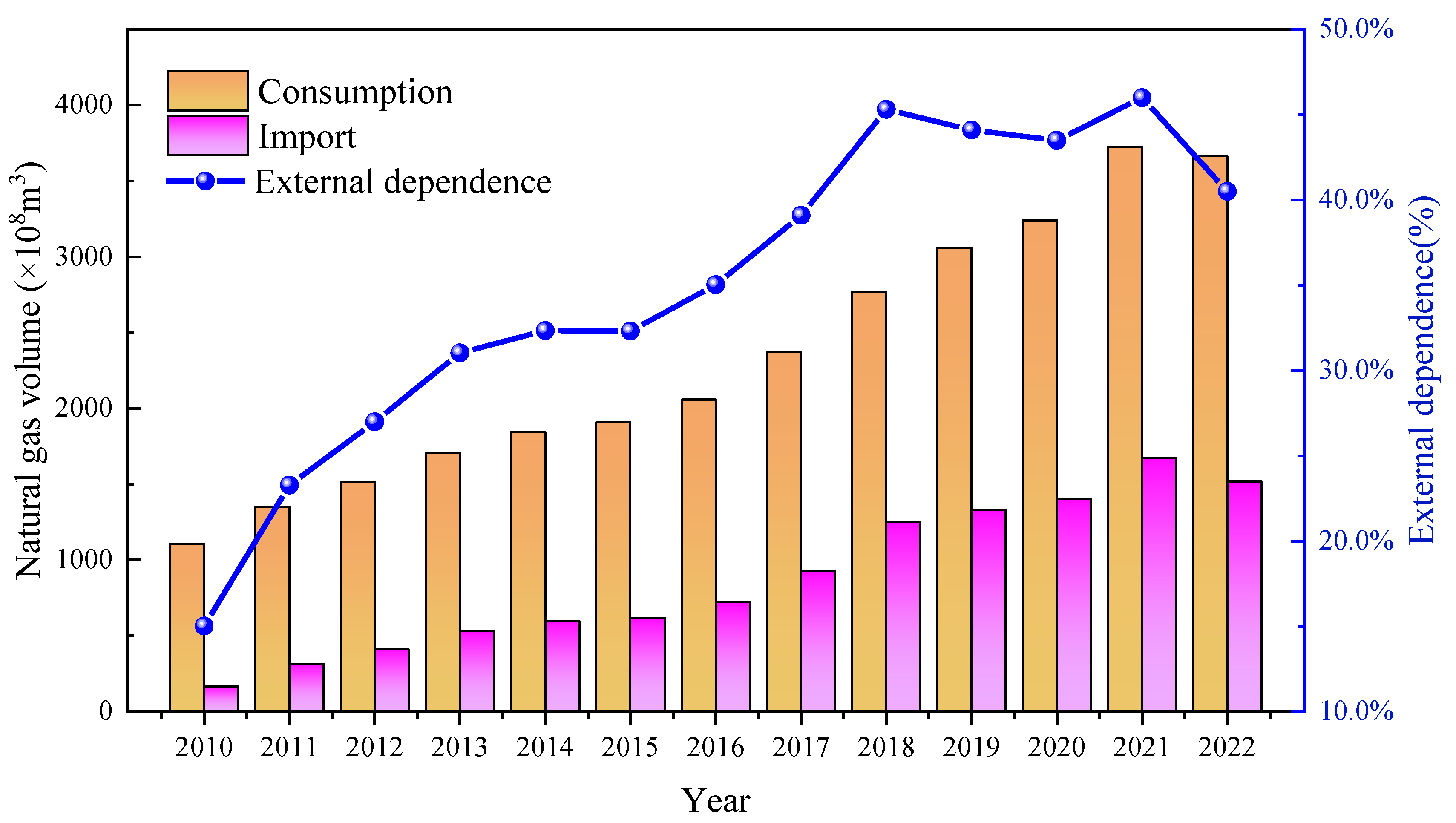
Natural gas is an important clean energy, and it is of great significance to energy transformation and carbon-neutral utilization in most countries. China’s natural gas consumption has continued to increase in recent years [1,2]. As shown in Figure 1, China’s natural gas consumption in 2022 is expected to reach 3.663 × 10¹¹ m3. About 45% of China’s natural gas consumption relies on importation, which may significantly threaten China’s energy security [3,4]. To improve the security of natural gas supply and its emergency peak shaving, it is meaningful to greatly increase natural gas storage capacity [5,6,7,8].

Figure 1.
The import and consumption of natural gas in China from 2010 to 2022.
The natural gas storage methods mainly include three aspects: surface storage tanks, pipeline storage, and underground gas storage (UGS) [9]. Underground gas storage utilizes underground space to store natural gas. It has the potential to address various issues, including uneven seasonal gas consumption due to large storage capacity and enhanced safety measures [10,11,12]. In China, depleted gas reservoirs and salt caverns are two main types of space for the underground gas storage. Among them, the storage capacity of natural gas in depleted gas reservoirs accounts for 90% in China, and their application and distribution are very extensive [13,14,15,16,17,18,19]. However, it should be noted that there are many domestic and international cases of sealing failure of underground gas storage. For example, serious losses occurred in one gas storage project in California, USA, due to gas migration and leakage to the surface along faults and caprocks [20]. The sealing failure of gas storage may cause a series of serious consequences, such as gas storage leakage, explosion, fire disaster, etc. [21]. Therefore, the evaluation on caprock sealing performance of underground gas storage should be carried out to ensure the safety of operation in underground gas storage.
The sealing performance of depleted oil and gas reservoirs, underground gas storage, CO2 storage, etc., was widely evaluated by using multi-index comprehensive evaluation methods. Wei et al. [22] constructed a dynamic sealing evaluation theory based on engineering data using a mathematical model. Masao et al. [23] analyzed the influence of rock mineral reactions on rock internal structure and long-term sealing ability. Xue et al. [24] used a two-phase flow model to consider the influence of the matrix and fracture and analyzed the influence of the CH4 adsorption and diffusion process on the sealing efficiency of caprock. Ouyang et al. [25] evaluated the sealing evolution process and impact factors of carbonate caprock using detailed laboratory experiments, such as thin section study, isotope analysis, and logging data. Harpreet et al. [26] proposed a fractured caprock with the random characterization of effective permeability. The sensitivity of four parameters of caprocks, including thickness, permeability, effective pressure, and injection rate, on the sealing performance of caprocks was studied. Fleury et al. [27] studied impacts of key parameters such as diffusion, reaction, and entry pressure, on the migration of CO2 in caprock for thousands of years, and the change in the sealing performance of caprock. Zhu et al. [28] studied the sealing ability of limestone caprock under different burial depths. Jin et al. [29] estimated the variation in sealing capacity of caprock during burial and uplift process. Hou et al. [30] studied the sealing ability of caprocks with different lithology. Wang et al. [31] studied the influence of fault activity on the sealing ability of caprocks. Blake et al. [32] studied the influence of thermal shock on the sealing performance of caprocks during CO2 injection. Newell et al. [33] studied the interaction between joints and faults. Zhou et al. [34] studied the influence of the porosity and permeability of caprocks on the breakthrough pressure of caprock and confirmed the influence of pore characteristics on the sealing performance of caprocks.
However, the selection of evaluation parameters is strongly subjective, which increases the uncertainty of evaluation results. This paper applied the fuzzy comprehensive evaluation method and established the parameter selection method and weight assignment criteria. Afterwards, this method was applied in the evaluation of caprock sealing ability in three underground gas storage projects planned or in construction.
2. Selection of Parameters Affecting the Sealing Performance of Caprocks
2.1. Sealing Mechanism of Caprocks
Sealing failure of caprocks in underground gas storage of depleted gas reservoirs can threaten the storage safety. Both microscopic and macroscopic characteristics can affect the sealing performance of caprocks. When the gas is injected into the target reservoir, it will gradually move upward to the bottom of caprocks. Gas will enter the pores of caprocks when the displacement pressure is larger than the capillary pressure. The gas breakthrough process of caprocks can be divided into three stages, as shown in Figure 2. In the first stage, gas enters the pores of caprocks, but there is no connected pore channel of gas. In the second stage, with the continuous increase in gas pressure in the reservoirs, a connected pore channel forms locally in the caprocks. In the third stage, when the gas-driving pressure is continuously higher than the gas breakthrough pressure in the caprocks, the pore water in the caprocks is replaced by gas, forming the dominant gas migration pathways. The liquid present in the pores will be displaced, and the gas will continuously migrate through the thick caprock, resulting in sealing failure of caprocks [35]. Therefore, gas breakthrough pressure is a key index reflecting the sealing performance of caprock. Additionally, the geometry of the pores will affect the displacement process [36,37].
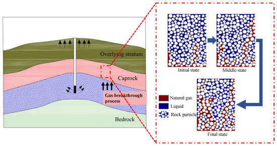
Figure 2.
Schematic of gas breakthrough process in the caprock with continuous injection of natural gas (the black arrows in the left figure represent the migration paths of gas).
Caprock thickness, mechanical properties, fault distribution, etc., are the macro factors that may affect the sealing ability of caprocks. If the thickness of caprock is too thin, the injected gas may easily penetrate the caprock and sealing failure occurs. Faults may cut through caprocks and cause sealing failure problems. But if the faults only partially cut into the interior of caprocks, the sealing of caprocks still works. The lithology will also affect the sealing of caprocks because different minerals can result in different capillary pressure. The failure mode of caprock is related to in situ stress state. With rapid gas extraction, the formation pressure of the reservoir drops rapidly, and the caprock will also be damaged [38,39].
2.2. Indicator Screening of Caprock Sealing Evaluation
Table 1 lists the main parameters (e.g., lithology, gas breakthrough pressure, porosity, permeability, thickness, fracture development degree, rock brittleness, and lateral continuity) in the sealing evaluation of caprocks by different researchers. It shows that the selection of parameters is strongly subjective.

Table 1.
Selected parameters in the evaluation of sealing performance of caprocks.
In this paper, six parameters, including gas breakthrough pressure (A), permeability (B), thickness (C), brittleness (D), fracture development degree (E), and porosity (F), are selected as the main evaluation indexes. To establish an evaluation standard for the sealing performance of caprocks, the weights of six selected factors should be reasonably assigned. The analytic hierarchy process (AHP) is often used to determine the weights of factors (see detailed steps of AHP in Appendix A.1). The key step of AHP is to establish the judgment matrix. Before assigning the weights of parameters, some related literatures are referenced [40,41,42,43,44]. The gas breakthrough pressure is four compared with the permeability, five compared with the thickness, five compared with the brittleness, three compared with the degree of fracture development, and four compared with the porosity, see details in Table 2.
Table 2.
The pairwise comparison matrix used in the sealing evaluation of caprocks.
The pairwise comparison matrix is calculated using AHP (see Appendix A.1 for the specific calculation process of AHP). The evaluation parameters and equations of six factors are obtained. When CR = 0.0988, it is less than 0.1, and the consistency test is satisfied, as shown in Table 3.
Table 3.
The weights of six factors affecting the caprock sealing performance.
Combined with the evaluation results, the evaluation equation for the sealing performance of caprock can be written as:
where A is the breakthrough pressure of caprock; B is the permeability of caprock; C is the thickness of caprock; D is the brittleness of caprock; E is the development degree of fracture; and F is the porosity of caprock.
3. Comprehensive Fuzzy Evaluation Method
3.1. Comprehensive Fuzzy Evaluation Theory
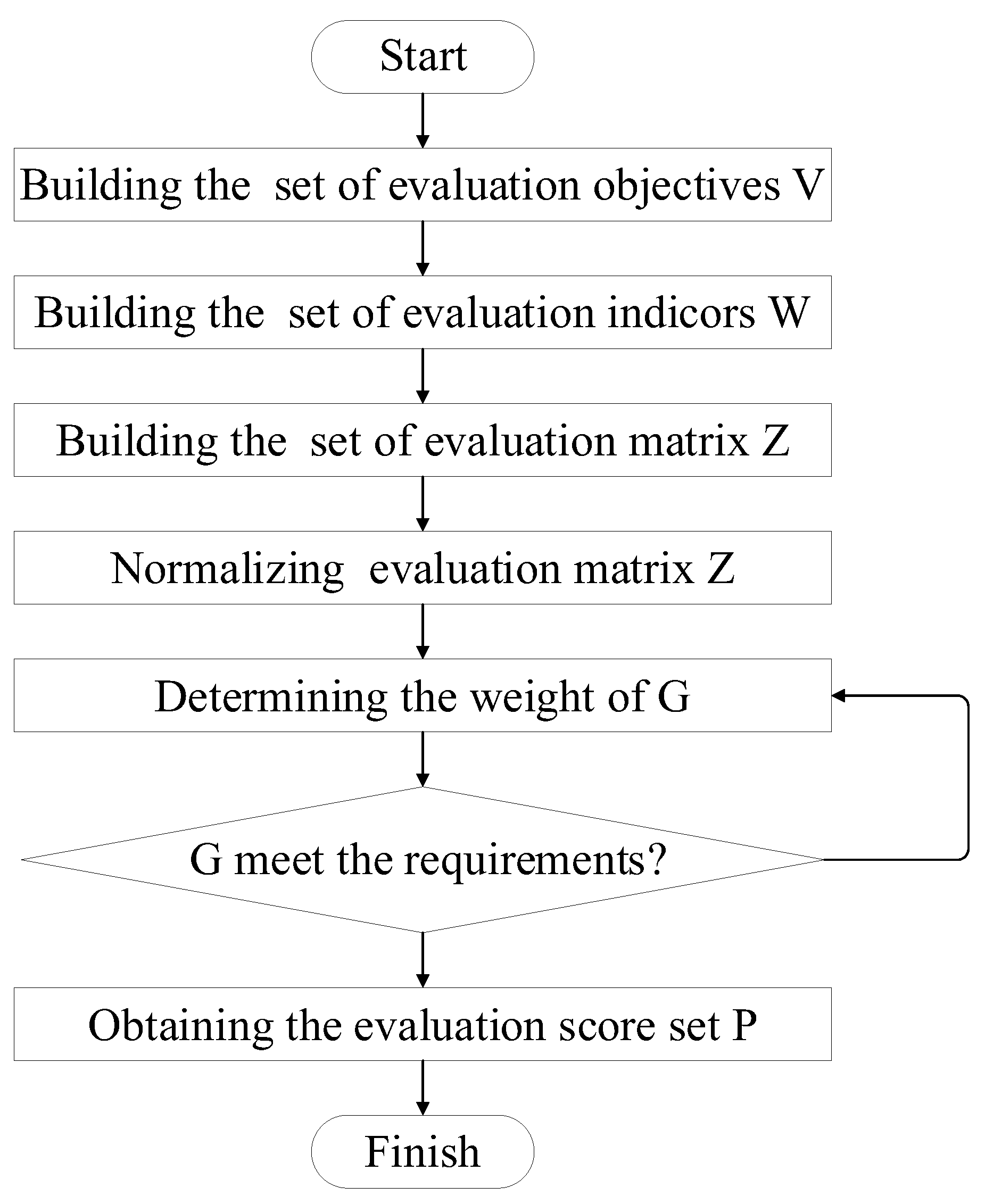
Fuzzy comprehensive evaluation method (FCEM) is a mathematical method to study and address fuzzy phenomena. It is a branch of mathematics put forward by Zade [45]. It has been widely applied in petroleum engineering and geology. Its main idea is to establish fuzzy sets, make fuzzy decisions, quantify qualitative indicators, and determine the membership function of each indicator. Then, the final evaluation result is established by combining the weight and membership functions, as shown in Figure 3.

Figure 3.
The procedure of fuzzy comprehensive evaluation method.
Compared with the traditional AHP, the FCEM eliminates some subjective intervention. The membership function cited by fuzzy mathematics theory makes the normalization of each index more standardized and establishes a fuzzy set and theoretical system of dynamic sealing evaluation of caprock.
3.2. Caprock Sealing Dynamic Evaluation
According to the fuzzy comprehensive evaluation theory, the qualitative and quantitative parameters that affect the sealing performance of caprocks are compared and comprehensively analyzed, and the normalized matrix is obtained. Then, combined with the weight of each element, the final evaluation standard system of sealing performance can be obtained. In addition, this method can also be used to evaluate the sealing performance of caprocks with different parameters. First, the relevant factors affecting the sealing performance of the caprocks are screened, then the influence of each factor is evaluated. Afterwards, single-factor fuzzy evaluation is carried out to obtain the evaluation matrix, determine the factor weight vector, and finally establish a comprehensive evaluation model.
Before using the FCEM, it is necessary to carry out one of the above six indexes and establish an evaluation index system of the sealing ability of caprocks, as shown in Table 4.
Table 4.
Grading of six parameters in the sealing ability evaluation of caprocks [46].
3.3. Classification of Parameters and Ranking Values
By using the bipolar scaling method [47], the elements involved in this study are divided into revenue elements and cost elements. The qualitative parameters mainly include the rock brittleness of the caprock and the degree of fracture development, which belong to revenue elements. While the rock brittleness and the degree of fracture development belong to cost elements, as shown in Table 5.
Table 5.
Classification of selected factors affecting the sealing performance of caprocks.
Before the evaluation, it is necessary to transform the qualitative indicators into quantitative values. The transform method uses bipolar scaling method, transforming qualitative indicators into quantitative indicators according to different attributes, as shown in Table 6.
Table 6.
Ranking of cost and revenue element.
Afterwards, the quantified matrix should be normalized for comparison. Different attributes of elements have different membership functions. Combined with the criteria for determining the membership function, it is mainly divided into cost elements and revenue elements. The principles for establishing the membership function of the two types of elements are different. For cost elements, the equation is as follows:
For the revenue element, its membership function is:
According to the attributes of each element, the membership function of each element is constructed:
4. Sealing Evaluation of Caprocks in Three UGSs Planned or in Construction
4.1. Geological Characteristics
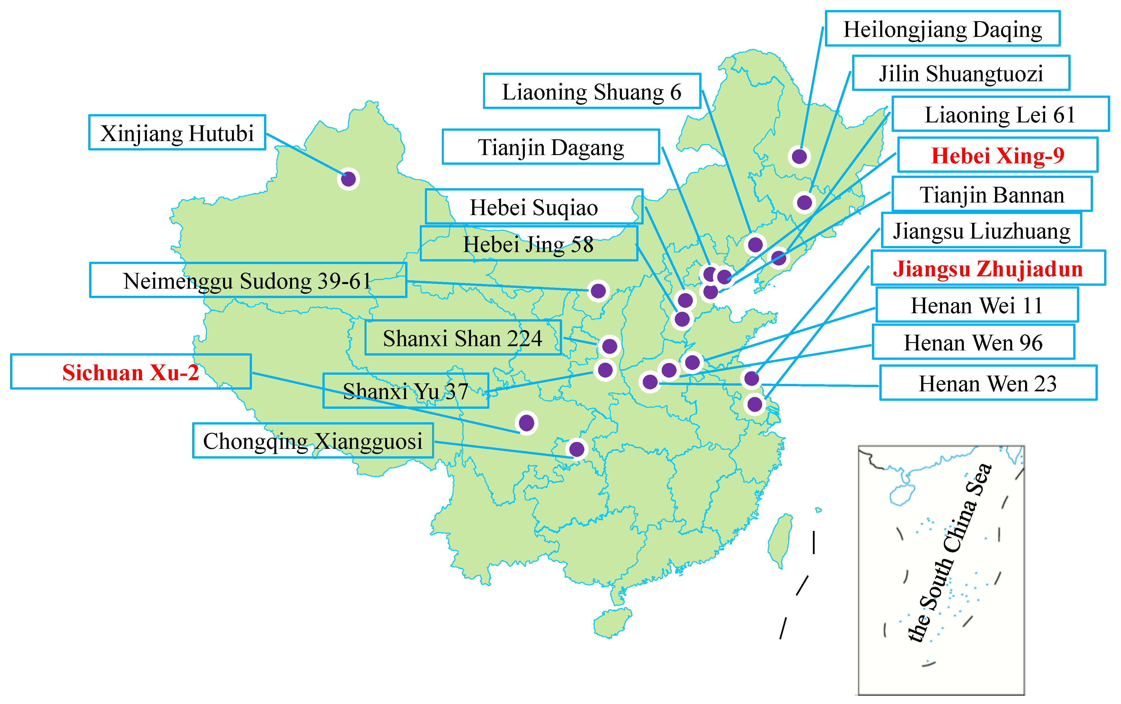
By the end of 2021, the current working gas volume of UGS projects in China reached approximately 16.4 billion m3, the details of all UGSs in operation are listed in Liu et al. [19]. In this paper, three depleted gas fields (e.g., Xing-9 gas field, Xu-2 gas reservoir of Zhongba gas field, Zhujiadun gas field) are selected for the rebuilding of underground gas storage, as shown in Figure 4.
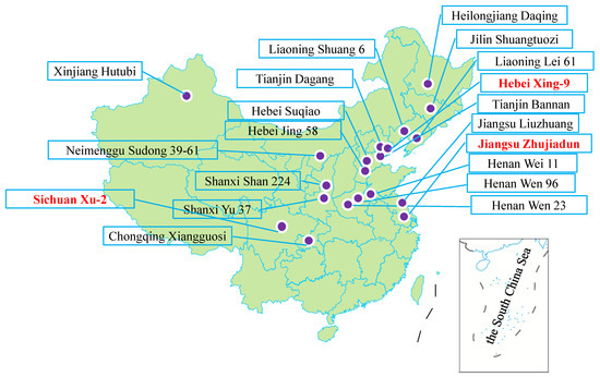
Figure 4.
Distribution of underground gas storage projects in depleted gas reservoirs in China (The three selected UGSs marked in red are planned or under-construction).
4.1.1. Xu-2 Gas Reservoir of Zhongba Gas Field
The Zhongba gas field is located in the front belt of Longmenshan in the northwest corner of the Sichuan Basin [48]. The daily water and gas production of Zhongba gas field is less than 150 m3/d and 2.0 × 10⁴ m3/d, respectively [49]. With the continuous development of gas reservoir, the formation pressure and geological conditions of the second member of Xu-2 Formation have changed obviously. The thickness, porosity, and permeability of the direct caprock have been obtained through petrophysical experiments. The lithology of caprock is mainly mudstone of the Ziliujing Formation and Shaximiao Formation [48]. The cumulative thickness of mudstone is 60–160 m, and the average thickness of caprock is 137 m. The porosity and permeability of mudstone are 1–7.4% and 0.0001–0.001 mD, respectively. The breakthrough pressure of the caprock measured by the mercury injection experiment is 8–50 MPa, with an average value of 26.4 MPa. The brittleness index of rocks is approximately 7.0–30.0, with an average value of 16.9, belonging to low–moderate brittle rocks [50]. The Xu-2 gas reservoir of Zhongba gas field is planned to be reestablished into an underground gas storage, and the sealing performance of the caprock should be carefully evaluated.
4.1.2. Xing-9 Gas Field
Xing-9 gas field, which is located in the hanging wall of the Daxing fault, is a typical lithologic gas reservoir with a depth of 4010 m and a temperature of about 120–130 °C and is surrounded by dark mudstone of the third member of the Shahejie Formation [51]. The thickness of the caprock is over 400 m, and it has good continuity. The porosity of the caprock is 2.16–8.92%, with an average value of 4.08%. The permeability of the caprock is 0.00116–0.0551 mD, and the average permeability is approximately 0.0223 mD. The gas breakthrough pressure of the caprock is higher than 20 MPa, with an average value of approximately 24 MPa. The brittleness index of caprocks in Xing-9 gas field is between 48.49 and 57.85, which indicates medium-low brittleness [52]. The test wells were drilled in the Xing-9 gas field before its reconstruction into an underground gas storage [53].
4.1.3. Zhujiadun Underground Gas Storage
The Zhujiadun gas field is located in Yancheng city, Jiangsu Province [54]. The development of Zhujiadun gas field started in May 2003. Till December 2020, the cumulative gas production reached 4.57 × 10⁸ m3. The caprock is mainly mudstone with a large thickness and stable lateral distribution. The main thickness of the caprock is approximately 400–600 m, the porosity is 0.06–0.60%, and the permeability is approximately 0.085 mD [40]. The construction of Zhujiadun gas storage started on 12 April 2022, with a designed storage capacity of m3 and a working gas volume of m3. At present, Zhu Chu 1-1, the first gas storage well in Zhujiadun gas storage has been completed, and the designed vertical well depth has reached 3835 m. Based on the geological conditions of three depleted gas fields, the main parameters for the evaluation of caprock’s sealing performance can be summarized in Table 7.
Table 7.
Main parameters obtained from three selected depleted gas fields.
4.2. Weights Assignment of Parameters and Sealing Evaluation in Three UGSs Based on FCE
According to methods described in the section above, the quantified matrix for the evaluation of three UGSs are written as:
According to the membership function, the final normalization matrix is determined as:
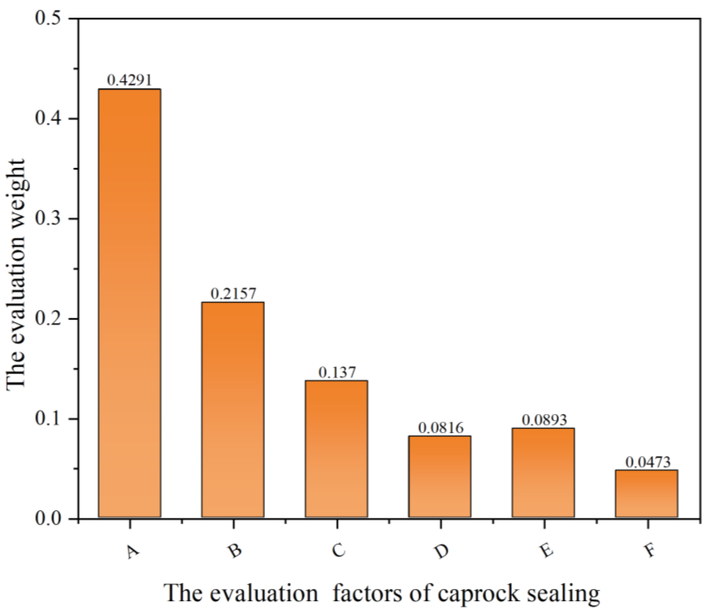
Finally, the weights of six parameters can be obtained, as shown in Figure 5, and the evaluation standard and system can be established. The pairwise comparison matrix of the above six parameters is established. The values of the relative importance of the above six parameters are explained, as shown in Table 2. Hierarchical analysis and calculation are carried out on the matrix to obtain the weights.
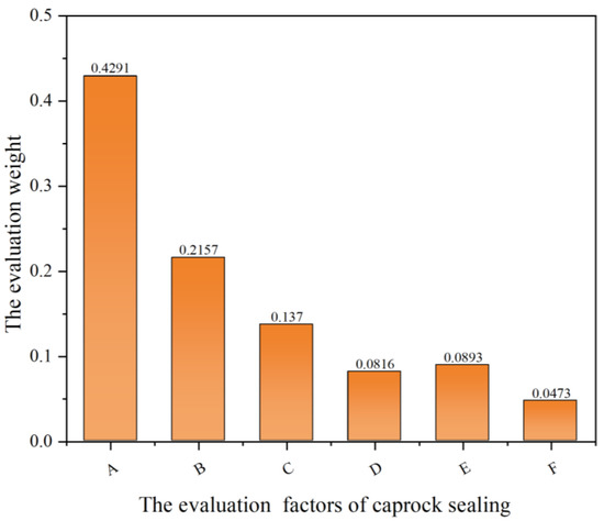
Figure 5.
The weights assignment of main factors affecting the sealing performance of caprocks.
The final weights obtained need to be tested, and the results meet the requirements. CI = 0.1245, CR = 0.0988, it is generally believed that CI < 1, and consistency meets the requirements. As shown in Figure 5, the results show that the breakthrough pressure has the greatest influence on the sealing performance of the caprock, followed by permeability and caprock thickness. Porosity has the least influence on the sealing performance of caprock. The CI obtained above is 0.1330, which meets the accuracy requirements. Therefore, the above weight results are credible. The overall sealing performance scores can be calculated as:
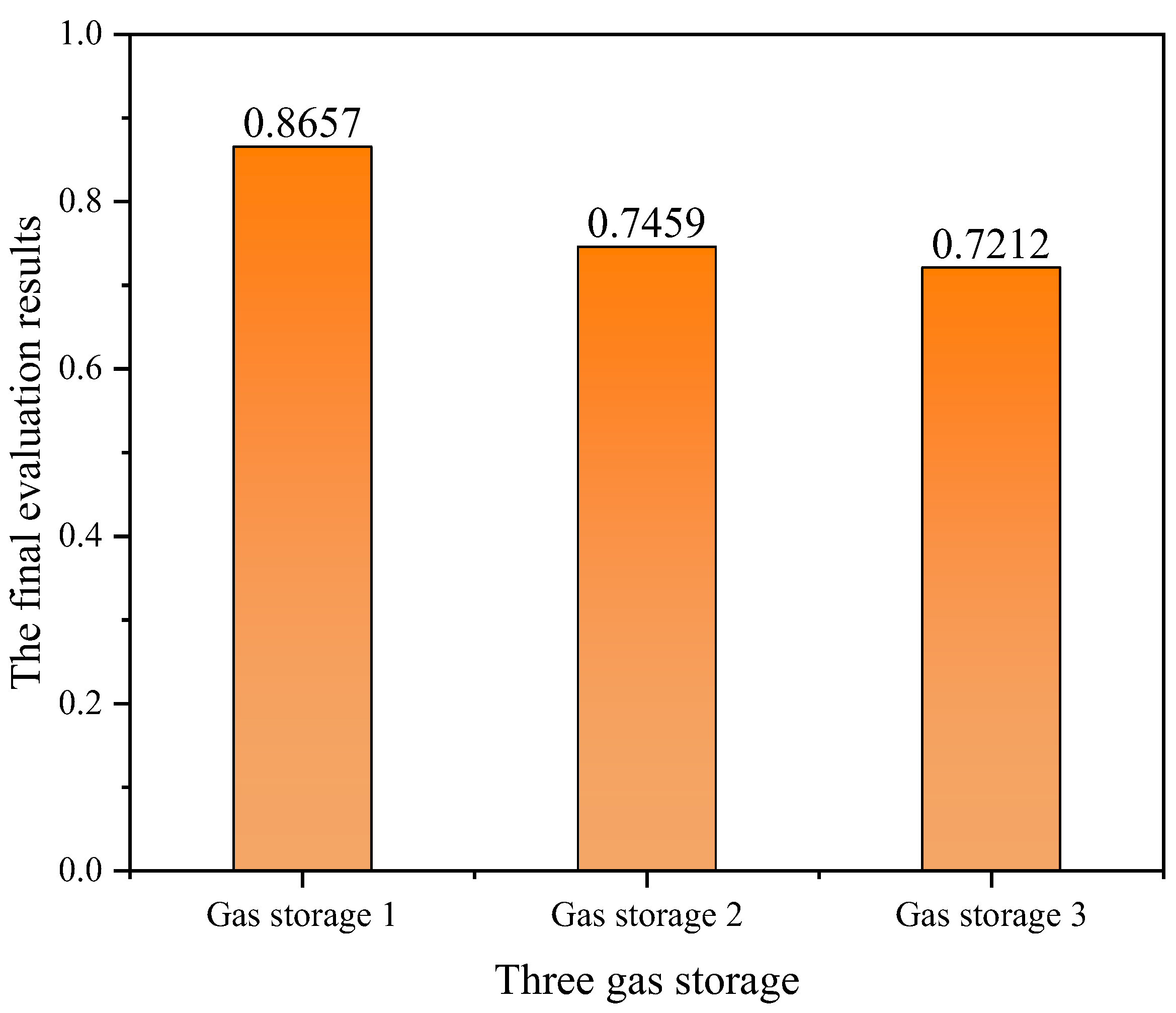
Based on the evaluation results, it implies that the Zhujiadun depleted gas field has the best sealing performance, while the Xu-2 depleted gas reservoir in Zhongba gas field in Northwest Sichuan, has the worst sealing performance, as shown in Figure 6.

Figure 6.
Evaluation results of caprock’s sealing performance of three underground gas storage.
4.3. Verification of Evaluation Results
Additionally, the maximum method is adopted to verify the accuracy of the evaluation results. In this study, the maximum value is 10. Taking the thickness of the caprock as an example, the thickness of caprocks in Zhujiadun gas field is the thickest among these three UGSs, and the score of caprock thickness in Zhujiadun gas field is 10, while the caprock thickness of Xing-9 is 400 m, and the score of Xing-9 is (400/500) × 10 = 8. The assignment of values for other factors follows a similar method. According to the above analysis results, the score of the six evaluation factors on three UGS can also be obtained; the score criteria is based on optimum method as shown in Table 8.
Table 8.
The assignment of values for six parameters in three depleted gas fields designed for underground gas storage.
According to the ranking grades in Table 4, the sealing of caprocks is divided into four aspects: good, generally good, medium, and bad. The detailed values of these four levels are 10, 8, 7, and 5. The comprehensive value M is proposed to evaluate the sealing of caprocks; the detailed equation is as follows:
where M is the comprehensive value, is the weight of six evaluation factors, and is the score of the gas storage. The evaluation criterion of the comprehensive values are listed in Table 9.
Table 9.
The comprehensive values of caprock sealing performance [52].
After the calculation, the final comprehensive values of Zhujiadun, Xing-9, and Xu-2 are 7.43, 6.71, and 6.67, respectively. From Table 9, we can see that the Zhujiadun caprocks show a good sealing ability, and it is suitable for the construction of underground gas storage. The evaluation result is in accordance with the actual engineering, which indicates that the evaluation method and comprehensive value is reasonable. From Table 9, the caprock sealing ability of Xu-2 and Xing-9 gas fields is medium, which requires further demonstration tests to analyze the feasibility of constructing the underground gas storage.
From the evaluation of three gas fields, the Zhujiadun has the best sealing performance, Xu-2 has the worst sealing performance. These results are similar to the fuzzy comprehensive evaluation results, which indicates that the accuracy of fuzzy comprehensive evaluation can be acceptable.
It should be noted that only six factors, such as breakthrough pressure, permeability, porosity, the thickness of caprock, brittleness, and crack development degree, are considered in this paper using the fuzzy comprehensive evaluation method. If more parameters, such as rock mechanical properties, are obtained, they can be also considered to update the evaluation models.
5. Conclusions
The dynamic sealing evaluation of caprocks is significant for the the sealing safety of UGSs in depleted gas reservoirs. The sealing performance of caprocks is a comprehensive evaluation process with complex multifactor indicators, and some main conclusions of are as follows:
- (1)
- Two main factors affect the sealing performance of the caprock: the thickness and mechanical properties. Microscopically, the pore structure, permeability, and breakthrough pressure also affect the sealing performance of the caprock.
- (2)
- Using the AHP method, the weights of six parameters for caprock’s sealing is obtained. The breakthrough pressure of the caprock and permeability are the main factors with the weights of 0.4291 and 0.2157, respectively.
- (3)
- Using the fuzzy comprehensive evaluation method (FCEM), the sealing performance of the caprocks in three planned UGSs was evaluated. Zhujiadun gas storage, which has the relative evaluation score of 0.731, implies that the caprocks have good sealing performance.
In the early stage of planning and rebuilding underground gas storages, using this method can provide a general assessment on the sealing ability of caprocks. However, some assumptions have been made in the evaluation, and six parameters are considered in the evaluation system. It is necessary to update the evaluation model when the database is renewed.
Author Contributions
S.B.: Data curation, Writing—Original Draft. H.L.: Conceptualization, Methodology, Writing—Reviewing and Editing. X.W.: Data Validation, Writing—Reviewing and Editing. X.S.: Data curation. H.M.: Supervision. Y.S.: Basic geological data collection. H.T.: Data collection. All authors have read and agreed to the published version of the manuscript.
Funding
This research was funded by the CAS Pioneer Hundred Talents Program (Y826031C01) and the National Natural Science Foundation (U22A20166).
Data Availability Statement
Not applicable.
Conflicts of Interest
The authors declare that they have no known competing financial interest or personal relationships that could have appeared to influence the work reported in this paper.
Appendix A
Appendix A.1. Analytical Hierarchy Process (AHP)
A basic principle of the analytic hierarchy process is to decompose a complex problem into its components. The relative importance of many factors in the hierarchy is determined by pairwise comparison. Table A1 displays the judgment matrix value. Its characteristics are as follows:
where and represent judgment matrix elements.
Table A1.
Comparison table of weighted impact factors.
Table A1.
Comparison table of weighted impact factors.
| Scale | Implication |
|---|---|
| 1 | Indicates that both factors are equally important compared to each other |
| 3 | Indicates that one factor is slightly more important than the other one when comparing the two factors |
| 5 | Indicates that one factor is significantly more important than the other when comparing the two factors |
| 7 | Indicates that one factor is strongly more important than the other when comparing the two factors |
| 9 | Indicates that one factor is extremely more important than the other when comparing the two factors |
| 2, 4, 6, 8 | Between two of the above two adjacent judgments |
A constructed matrix is calculated as follows:
where represent elements in the matrix and represent elements of the normalized matrix. The columns of the normalized matrices are summed.
where represents the matrix that was summed by row. The vectors are then normalized to obtain the relative weights.
where is the relative importance weight of the th factor under a certain criterion.
- (1)
- AHP accuracy verification
The accuracy of AHP indicators includes two indicators: consistency index (CI) and random consistency index (RI). The equation of CI is as follows:
where is the maximum eigenvalue and n represents the order of the matrix. The greater the CI is, the more serious the inconsistency of the matrix and the lower the accuracy of the model.
The other index RI is related to the order of the matrix. The detailed correspondence is shown in Table A2, the random consistency index (RI), and the equation of RI is as follows:
The exponent is related to CI and the order of the matrix. As the CI is larger, the inconsistency of the matrix is more serious, and the accuracy of the model is lower. If CI = 0, the model meets the accuracy requirements.
Table A2.
Random consistency indexes (RI).
Table A2.
Random consistency indexes (RI).
| The Order of the Matrix | 1 | 2 | 3 | 4 | 5 | 6 | 7 | 8 | 9 | 10 |
|---|---|---|---|---|---|---|---|---|---|---|
| RI | 0 | 0 | 0.58 | 0.90 | 1.12 | 1.24 | 1.32 | 1.41 | 1.45 | 1.49 |
Combined with the CI and RI, the accuracy index CR is obtained:
If , the accuracy of the model is satisfied.
Appendix A.2. Fuzzy Comprehensive Evaluation Method (FCEM)
Many factors should be considered in a complex analysis and evaluation system. This fuzzy comprehensive evaluation model can be used in the evaluation of the sealing performance of caprocks. The theory of fuzzy mathematics is a fuzzy set method proposed by American expert A Zadeh [45], and the calculation steps are as follows:
- (1)
- Determining the set of evaluation objectives V:
- (2)
- Determining the evaluation parameter W for the set of evaluation objectives V:
- (3)
- Various parameters are evaluated, and an evaluation matrix Z is obtained, where Z is a n × m matrix.
- (4)
- Normalizing the evaluation matrix Z using the membership function, the method of obtaining the membership function is given.
- (5)
- Use AHP to determine the weight of G, and each evaluation index W has its corresponding weight. The first step of AHP is to construct the judgment matrix H, and its equation is as follows:
Then, the sum of the elements of each row of is obtained:
The relative weights of the elements of are obtained,
Then, the consistency indicators CI and consistency ratio RI are calculated.
where is the maximum eigenvalue and n is the order of the matrix.
If , the accuracy of the model is satisfied.
- (6)
- Fuzzy calculation to obtain the evaluation score set P
References
- Wang, X.L.; Economides, M.J. Purposefully established underground natural gas storage. J. Nat. Gas Sci. Eng. 2012, 9, 130–137. [Google Scholar] [CrossRef]
- Lyu, X.; Yun, L.; Xu, J.; Liu, H.; Yu, X.; Peng, P.; Ouyang, M.; Luo, Y. Sealing capacity evolution of gypsum salt caprocks under multi-cycle alternating stress during operations of underground gas storage. J. Pet. Sci. Eng. 2023, 220, 111244. [Google Scholar] [CrossRef]
- Teatini, P.; Castelletto, N.; Ferronato, M.; Gambolati, G.; Janna, C.; Cairo, E.; Marzorati, D.; Colombo, D.; Ferretti, A.; Bagliani, A.; et al. Geomechanical response to seasonal gas storage in depleted reservoirs: A case study in the Po River basin, Italy. J. Geophys. Res. Earth Surf. 2011, 116. [Google Scholar] [CrossRef]
- Malakooti, R.; Azin, R. The optimization of underground gas storage in a partially depleted gas reservoir. Pet. Sci. Technol. 2011, 29, 824–836. [Google Scholar] [CrossRef]
- Jeanne, P.; Zhang, Y.; Rutqvist, J. Influence of hysteretic stress path behavior on seal integrity during gas storage operation in a depleted reservoir. J. Rock Mech. Geotech. Eng. 2020, 12, 886–899. [Google Scholar] [CrossRef]
- Zhang, N.; Shi, X.; Zhang, Y.; Shan, P. Tightness analysis of underground natural gas and oil storage caverns with limit pillar widths in bedded rock salt. IEEE Access 2020, 8, 12130–12145. [Google Scholar] [CrossRef]
- Zhechao, W.; Wei, L.; Jie, L. A review on state-of-the-art of underground gas storage and causes of typical accidents. Hazard Control Tunn. Undergr. Eng. 2019, 1, 49–58. [Google Scholar]
- Xu, Q.; Liu, H.; Song, Z.; Dong, S.; Zhang, L.; Zhang, X. Dynamic risk assessment for underground gas storage facilities based on Bayesian network. J. Loss Prev. Process Ind. 2023, 82, 104961. [Google Scholar] [CrossRef]
- Yu, H.; Yi, Y.; Romagnoli, A.; Tan, W.L. Cement soil stabilization for underground liquid natural gas storage. Cold Reg. Sci. Technol. 2022, 194, 103438. [Google Scholar] [CrossRef]
- Sadeghi, S.; Sedaee, B. Mechanistic simulation of cushion gas and working gas mixing during underground natural gas storage. J. Energy Storage 2022, 46, 103885. [Google Scholar] [CrossRef]
- Wang, H.; Li, H.; Ren, Z. Modeling multiphase fluid flow and salt precipitation due to water vaporization in producing wells of underground gas storage. Gondwana Res. 2023. [Google Scholar] [CrossRef]
- Yousefi, S.H.; Groenenberg, R.; Koornneef, J.; Juez-Larré, J.; Shahi, M. Techno-economic analysis of developing an underground hydrogen storage facility in the depleted gas field: A Dutch case study. Int. J. Hydrogen Energy 2023, 48, 28824–28842. [Google Scholar] [CrossRef]
- Chen, S.; Zhang, Q.; Wang, G.; Zhu, L.; Li, Y. Investment strategy for underground gas storage facilities based on real option model considering gas market reform in China. Energy Econ. 2018, 70, 132–142. [Google Scholar] [CrossRef]
- Ding, G.; Li, C.; Wang, J.; Xu, H.; Zheng, Y.; Wanyan, Q.; Zhao, Y. The status quo and technical development direction of underground gas storages in China. Nat. Gas Ind. B 2015, 2, 535–541. [Google Scholar] [CrossRef]
- Zhang, G.; Li, B.; Zheng, D.; Ding, G.; Wei, H.; Qian, P.; Li, C. Challenges to and proposals for underground gas storage (UGS) business in China. Nat. Gas Ind. B 2017, 4, 231–237. [Google Scholar] [CrossRef]
- Zhang, J.; Tan, Y.; Zhang, T.; Yu, K.; Wang, X.; Zhao, Q. Natural gas market and underground gas storage development in China. J. Energy Storage 2020, 29, 101338. [Google Scholar] [CrossRef]
- Zhao, X.; Al-Abdrabalnabi, R.; Wu, Y.-S.; Zhou, X. Evaluations of the feasibility of oil storage in depleted petroleum reservoirs through experimental modellling studies. Fuel 2021, 294, 120316. [Google Scholar] [CrossRef]
- Zhang, S.; Shi, L.; Jia, D. An uncertainty quantitative model of wellbore failure risk for underground gas storage in depleted gas reservoir during the construction process. J. Energy Storage 2023, 57, 106144. [Google Scholar] [CrossRef]
- Liu, H.; Yang, C.; Liu, J.; Hou, Z.; Xie, Y.; Shi, X. An overview of underground energy storage in porous media and development in China. Gas Sci. Eng. 2023, 117, 205079. [Google Scholar] [CrossRef]
- Xie, L.; Zhang, H.; Li, H. Accident analysis and risk identification of underground gas storage with depleted oil and gas reservoirs. Nat. Gas Ind. 2009, 29, 116–119. [Google Scholar]
- Shen, X.; Liu, H.; Mu, L.; Lyu, X.; Zhang, Y.; Zhang, W. A semi-analytical model for multi-well leakage in a depleted gas reservoir with irregular boundaries. Gas Sci. Eng. 2023, 114, 204979. [Google Scholar] [CrossRef]
- Wei, X.; Shi, X.; Hu, W.; Ban, S.; Li, Y.; Ma, H.; Li, P.; Yang, C. Dynamic tightness evaluation of salt cavern energy storage. J. Energy Storage 2023, 57, 106313. [Google Scholar] [CrossRef]
- Sorai, M. Evaluation of Geochemical Impacts on Caprock’s Sealing Performance. Energy Procedia 2017, 114, 3578–3581. [Google Scholar] [CrossRef]
- Xue, Y.; Liu, J.; Dang, F.; Liang, X.; Wang, S.; Ma, Z. Influence of CH4 adsorption diffusion and CH4-water two-phase flow on sealing efficiency of caprock in underground energy storage. Sustain. Energy Technol. Assess. 2020, 42, 100874. [Google Scholar] [CrossRef]
- Ouyang, S.; Lü, X.; Quan, H.; Awan, R.S.; Zhou, J.; Wang, R. Evolution process and factors influencing the tight carbonate caprock: Ordovician Yingshan Formation from the northern slope of the Tazhong uplift, Tarim Basin, China. Mar. Pet. Geol. 2023, 147, 105998. [Google Scholar] [CrossRef]
- Singh, H.; Dilmore, R.M. Stochastic prediction of fractured caprock by history matching pressure monitoring data. J. Pet. Sci. Eng. 2019, 179, 615–630. [Google Scholar] [CrossRef]
- Minardi, A.; Stavropoulou, E.; Kim, T.; Ferrari, A.; Laloui, L. Experimental assessment of the hydro-mechanical behavior of a shale caprock during CO2 injection. Int. J. Greenh. Gas Control 2021, 106, 103225. [Google Scholar] [CrossRef]
- Zhu, A.; Liu, J.; Ding, G.; Wu, Z.; Shi, X.; Zeng, Y. Experimental investigation on permeability, meso-damage and fractal characteristics of limestone caprock under THM coupling based on μCT technology. J. Pet. Sci. Eng. 2022, 212, 110197. [Google Scholar] [CrossRef]
- Jin, Z.; Yuan, Y.; Sun, D.; Liu, Q.; Li, S. Models for dynamic evaluation of mudstone/shale cap rocks and their applications in the Lower Paleozoic sequences, Sichuan Basin, SW China. Mar. Pet. Geol. 2014, 49, 121–128. [Google Scholar] [CrossRef]
- Hou, L.; Yu, Z.; Luo, X.; Wu, S. Self-sealing of caprocks during CO2 geological sequestration. Energy 2022, 252, 124064. [Google Scholar] [CrossRef]
- Wang, F.; Chen, D.; Wang, Q.; Du, W.; Chang, S.; Wang, C.; Tian, Z.; Cheng, M.; Yao, D. Quantitative evaluation of caprock sealing controlled by fault activity and hydrocarbon accumulation response: K gasfield in the Xihu Depression, East China Sea Basin. Mar. Pet. Geol. 2021, 134, 105352. [Google Scholar] [CrossRef]
- Blake, O.; Faulkner, D.; Worden, R.; Armitage, P.; Espie, A. Effect of thermal shock on the permeability and seismic wave velocity of the caprock and reservoir during CO2 injection. Int. J. Greenh. Gas Control 2022, 118, 103691. [Google Scholar] [CrossRef]
- Newell, P.; Martinez, M.J. Numerical assessment of fault impact on caprock seals during CO2 sequestration. Int. J. Greenh. Gas Control 2020, 94, 102890. [Google Scholar] [CrossRef]
- Zhou, X.; Lü, X.; Sui, F.; Wang, X.; Li, Y. The breakthrough pressure and sealing property of Lower Paleozoic carbonate rocks in the Gucheng area of the Tarim Basin. J. Pet. Sci. Eng. 2022, 208, 109289. [Google Scholar] [CrossRef]
- Liu, H.; Zhu, Z.; Patrick, W.; Liu, J.; Lei, H.; Zhang, L. Pore-scale numerical simulation of supercritical CO2 migration in porous and fractured media saturated with water. Adv. Geo-Energy Res. 2020, 4, 419–434. [Google Scholar] [CrossRef]
- Iraji, S.; Soltanmohammadi, R.; Munoz, E.R.; Basso, M.; Vidal, A.C. Core scale investigation of fluid flow in the heterogeneous porous media based on X-ray computed tomography images: Upscaling and history matching approaches. Geoenergy Sci. Eng. 2023, 225, 211716. [Google Scholar] [CrossRef]
- Soltanmohammadi, R.; Iraji, S.; De Almeida, T.R.; Munoz, E.R.; Fioravanti, A.R.; Vidal, A.C. Insights into Multi-Phase Flow Pattern Characteristics and Petrophysical Properties in Heterogeneous Porous Media. In Conference Insights into Multi-Phase Flow Pattern Characteristics and Petrophysical Properties in Heterogeneous Porous Media; European Association of Geoscientists & Engineers: Utrecht, The Netherlands, 2021; Volume 2021, pp. 1–5. [Google Scholar]
- Orlic, B.; Wassing, B. A study of stress change and fault slip in producing gas reservoirs overlain by elastic and viscoelastic caprocks. Rock Mech. Rock Eng. 2013, 46, 421–435. [Google Scholar] [CrossRef]
- Defoort, T.; Salimzadeh, S.; Paluszny, A.; Zimmerman, R. A finite element geomechanical study of the brittle failure of a caprock due to deflation. In Conference a Finite Element Geomechanical Study of the Brittle Failure of a Caprock due to Deflation; ARMA: Westfield, MA, USA, 2015; pp. 2015–2352. [Google Scholar]
- Ao, L.; Lin, B. Sealability evalution of Zhujiadun underground gas storage. Complex Oil Gas Reserv. 2021, 14, 86–90. (In Chinese) [Google Scholar]
- Shu, P.; Gao, T.; Wang, H.; Liang, H. Caprock sealing-property classifying standard and evalution of Shengping gas storage in Daqing Oilfiled. Daqing Pet. Geol. Dev. 2019, 38, 272–276. (In Chinese) [Google Scholar]
- Qin, Y. Study on Sealing Performance of Caprock in Exhausted Reservoir Gas Storage. Master’s Thesis, Jilin University, Changchun, China, 2022. (In Chinese). [Google Scholar]
- Teng, S.; Zhang, P.; Jia, S.; Xu, M.; Zhang, G.J. Study on dynamic sealing evalution of carbonate gas storage caprock. Nat. Gas Oil 2022, 40, 98–107. (In Chinese) [Google Scholar]
- Hou, Y.; Wu, Z.; Qi, H.; Wang, Y.; Ran, L. Assessment on cap rock tightness of the Gas storehouse of Anning salt cavern. China Well Miner. Salt 2013, 44, 16–19. (In Chinese) [Google Scholar]
- Li, Y.; Sun, Z.; Han, L.; Mei, N. Fuzzy comprehensive evaluation method for energy management systems based on an internet of things. IEEE Access 2017, 5, 21312–21322. [Google Scholar] [CrossRef]
- Jia, S.; Jin, S.; Zheng, D.; Meng, Q.; Zhang, H.; Lin, J. Evaluation indices and classification criterion of aquifer site for gas storage. Chin. J. Rock Mech. Eng. 2015, 34, 1628–1640. [Google Scholar]
- Hartenian, L.S.; Bobko, P.; Berger, P.K. An Empirical Validation of Bipolar Risk Perception Scaling Methods 1. J. Appl. Soc. Psychol. 1993, 23, 335–351. [Google Scholar] [CrossRef]
- Zhang, B.; Wang, X.; Zhang, C.; Wang, X.; Sang, Q. Recognition of tight sandstone reservoir characteristics and development potential of the 2nd member of Xujiahe gas reservoir in Zhongba gas field. Eval. Dev. Oil Gas Reserv. 2019, 9, 10–15. (In Chinese) [Google Scholar]
- Zhu, X. Optimization demonstration of gas lift pipe network in Xu-2 gas reservoir of Zhongba gas field. Chem. Enterp. Manag. 2019, 1, 215–216. (In Chinese) [Google Scholar]
- Liu, L.; Sang, Q.; Cao, J.; Zhang, C.; Wang, X.; Deng, Q. Comprehensive evalution of sealing capacityof depleted gas reservoir reconstructed to gas storage: A case study of Xu-2 gas reservoir in Zhongba gas field, northwest Sichuan. Pet. Geol. Oilfield Dev. Daqing 2022, 41, 42–50. (In Chinese) [Google Scholar]
- Zhan, M.; Wu, Y.; Wang, Y.; Wang, H.; Su, W.; He, Y. Study on the development characteristics and technology strategies for the Xing 9 condensate gas reservoir. Nat. Gas Geosci. 2013, 24, 1022–1026. [Google Scholar]
- Lin, J.; Jia, S.; Liu, T.; Yan, H.; Xi, Z. Comprehensive evalution of sealing ability of mudstone caprock for Xing 9 depleted gas reservoir in reconstrucyion underground gas storage. Chin. J. Rock Mech. Eng. 2015, 34, 4099–4107. (In Chinese) [Google Scholar]
- Wang, X.; Liu, M.; Wang, Y.; Zhang, Y.; Qiu, A. One-time up-return cementing in Xing-9 conglomerate gas storage. Spec. Oil Gas Reserv. 2017, 24, 153–156. (In Chinese) [Google Scholar]
- Wang, G.; Cheng, T.; Lu, L.; Ren, C.; Huang, X. Relationship between near-surface expressions of hydrocarbon microseepage and migration pathways pathways-A case study in the Zhujiadun gas field, the Yancheng sag, the northern Jiangsu Basin. Pet. Exp. Geol. 2008, 30, 302–306. (In Chinese) [Google Scholar]

Disclaimer/Publisher’s Note: The statements, opinions and data contained in all publications are solely those of the individual author(s) and contributor(s) and not of MDPI and/or the editor(s). MDPI and/or the editor(s) disclaim responsibility for any injury to people or property resulting from any ideas, methods, instructions or products referred to in the content. |
© 2023 by the authors. Licensee MDPI, Basel, Switzerland. This article is an open access article distributed under the terms and conditions of the Creative Commons Attribution (CC BY) license (https://creativecommons.org/licenses/by/4.0/).