Abstract
After being processed into a certain shape by a stirrup bending machine, steel bars are used as the skeleton of reinforced concrete in construction. The accuracy of their bending directly affects the bearing capacity of reinforced concrete. In order to improve the accuracy of the springback angle of steel bars after bending, this paper focuses on optimizing the structural parameters of the steel bar bending machine and controlling the springback angle of steel bars. The influence of the support shaft diameter, bending crankshaft diameter, and bending crankshaft radius on the springback angle of steel bars is analyzed using ANSYS explicit dynamic simulation and experimental analysis. By combining orthogonal experimental methods, the bending structural parameters were optimized, including a support shaft diameter of 20 mm, a crankshaft bending diameter of 40 mm, and a crankshaft bending radius of 80 mm. This can effectively reduce the springback angle of the steel bars and improve the accuracy of the bending angle after bending. In addition, in order to improve the control accuracy of the steel bar springback angle, a cubic spline interpolation method was proposed, and the collected steel bar springback angle data were fitted using Matlab. At the same time, comparisons were made between the least squares method, polynomial interpolation method, and cubic spline interpolation method. The results show that the compensation formula obtained by using the cubic spline interpolation method can effectively improve the control accuracy of the steel bar bending springback angle.
1. Introduction
Steel bars are the main material of building structures, and their use is huge and increasing year by year. In order to facilitate transportation, most of the steel bars produced by factories are transported in disc shape. However, in the construction process, it is necessary to straighten, bend, and cut the steel bars, and process them into various sizes and shapes according to actual needs [1,2,3,4,5,6,7,8,9,10,11,12,13,14,15,16,17,18,19,20,21,22,23]. With the development and application of computer technology, intelligent steel processing machinery continues to emerge, the quality of steel bar products processed has also been greatly improved, and the gap with foreign steel processing equipment is also shortening. Wang Liangwen and others designed and developed the GWG20 automatic angle steel bar hoop bending machine, in which the angle of the hoop is determined mechanically, the angle can be continuously changed according to actual needs, the equipment cost is low, and the reliability is high [4]. According to the working principle and control requirements of the 5/12 automatic steel bar bending machine, Liu Le and others designed a numerical control system for the 5/12 automatic steel bar bending machine, established the mathematical model of the servo system by analytical method, and studied its stable performance, steady-state performance, and dynamic performance, which improved the intelligent level of the steel bar hoop bending machine [5]. Chen Kangyuan and others carried out simulation analysis and research on the forming mechanism of steel bar straightening and cutting and hoop bending, and they analyzed the relationship between stress, strain, and various curvatures in the process of steel bar straightening from the straightening theory, which provided a reference for the theoretical research of a hoop bending machine [6]. Li Yang and others used the μC/OS-II real-time operating system and STM32 embedded processor to design a new hoop bending machine control platform and completed the hardware structure design and the migration and modification of the operating system according to the requirements of the hoop bending machine control platform [7]. Yuan Zhipeng and others creatively proposed a new structure for a double stirrup die stirrup bending machine, and they used ANSYS/LS-DYNA finite element analysis software to establish a finite element model of the stirrup bending system, simulating the process of steel bar bending and verifying the reliability of the structure [8]. Jiang Ying and others further optimized the structure and system of the existing steel bar bending machine and designed a steel bar bending machine with adjustable support, which fully meets the requirements of modern steel bar bending machines, reduces costs, and realizes the miniaturization of the steel bar bending machine [9]. Xiao Wenhao and others developed a pure hydraulic five-head steel bar bending machine composed of five bending heads, I-beam machine base, pure hydraulic drive system, and control system, which has convenient and reliable positioning of the machine head and a stable control system, in order to realize multi-line efficient and high-quality processing of stirrups [10]. R. Sasikala and others improved the existing hydraulic steel bar hoop bending machine with a pneumatic system, reducing costs and increasing productivity [11]. Zhou Zeyun and others designed a new type of steel bar bending mechanism, which realized the process of putting the steel bar into the mesh first and then bending. The mechanism not only meets the requirements of the process of putting the steel bar first into the mesh and then bending but also serves as the actuator of the six-axis robot to further realize the intelligent control of the steel bar bending process [12]. In recent years, studies have shown that the steel bar bending machine is an important piece of equipment for steel bar processing, and a large number of scholars have studied its structure and control system; therefore, new products, new processes, and new technologies are constantly emerging.
However, steel bar bending hoop processing belongs to processes of elastoplastic deformation and complex deformation at the same time [13,14,15]; the residual stress in the reinforcement during the processing will cause the hoop angle to spring back, thus affecting the product quality and accuracy. Yan Shuli and others carried out bending hoop experiments at different angles on steel bars of different materials and specifications; by establishing a mathematical model, the experimental data were compared with the theoretical calculation results, and the experimental data were used to modify the theoretical calculation formula so that the theoretical calculation formula of the springback angle was more perfect [16]. Cai Wei and others used ABAQUS analysis software to simulate the coreless bending of an OCr18Ni9 pipe and studied the influence of process parameters such as bending angle, bending speed, and wall thickness on the bending springback angle of the material [17]. Zheng Xijian and others used ANSYS/LS-DYNA finite element analysis software to analyze the influencing factors of steel bar bending and forming on the springback angle, finally analyzed the significance of the influencing factors of the springback angle by orthogonal experimental method, and modified the springback angle formula [18]. Shang Zhongping applied MARC finite element software to establish a bending model and analyzed the effects of bending hoop speed and bending axis rotation radius on the springback angle [19]. Zhu Chaoqiang conducted a large number of bending and forming experiments on 1Cr18Ni9Ti pipe, analyzed the factors affecting the bending springback of the pipe, and concluded that the springback angle increased with the increase in bending angle and relative bending radius [20]. Chen Hua used DynaForm simulation software to analyze the influence of yield strength on the resilience performance of V-shaped parts by taking HC550/980DP, HC700/980DP, and HC980FG high-strength steels of different yield strengths as research objects [21]. Guo Long and others used the three-point bending experimental device to conduct bending experiments on 1500 MPa ultra-high-strength martensitic steel and analyzed the effects of downward pressure speed, thickness, bending radius, and relative bending radius on the bending resilience of materials [22]. He Xu developed an online measurement technology for monitoring rotational tensile bending springback that uses a laser transmitter and receiving device to detect part displacement changes; because the laser measurement method does not need the workpiece to be removed from the tooling system, this method was created to improve product quality and productivity while improving the flexibility of the production route [23]. Mai Rui proposed a compensation mechanism based on the principle of implicit equation iteration, so that the final shape of the part converges to the target shape through iterative finite compensation [24]. Wang Zili and others provided a numerical approximation springback prediction and compensation method for SVC MT, compared the calculation accuracy of the three springback numerical approximation methods, and concluded that the Runge–Kutta method has the highest prediction accuracy [25]. Wu Peijun and others used DynaForm software to perform springback simulation experiments on L-shaped parts and analyzed the thickness, edge pressing force, and corner radius of the concave and convex die by orthogonal test method [26]. The above study finds that the problem of bending springback is common in the material molding process, which seriously affects the accuracy and quality of finished parts, and springback control is a complex and urgent research topic.
Based on the above research analysis and shortcomings, this paper first uses ANSYS explicit dynamics to simulate steel bar bending and analyzes the magnitude and distribution of steel bar stress after bending under different support shaft diameters, bending shaft diameters, and bending shaft rotation radii. Then, the influence of the diameter of the support shaft, the diameter of the bending shaft, and the radius of rotation of the bending shaft on the springback angle of the steel bar is analyzed by experiments, and the optimal structural parameters are obtained by orthogonal test method. Finally, by comparing the advantages and disadvantages of various fitting methods, the springback compensation formula using the cubic spline interpolation method is proposed to improve the control accuracy of the steel bar bending springback angle.
2. Bending Mechanism of Steel Bar Bending Machine
2.1. Bending Mechanism and Working Principle
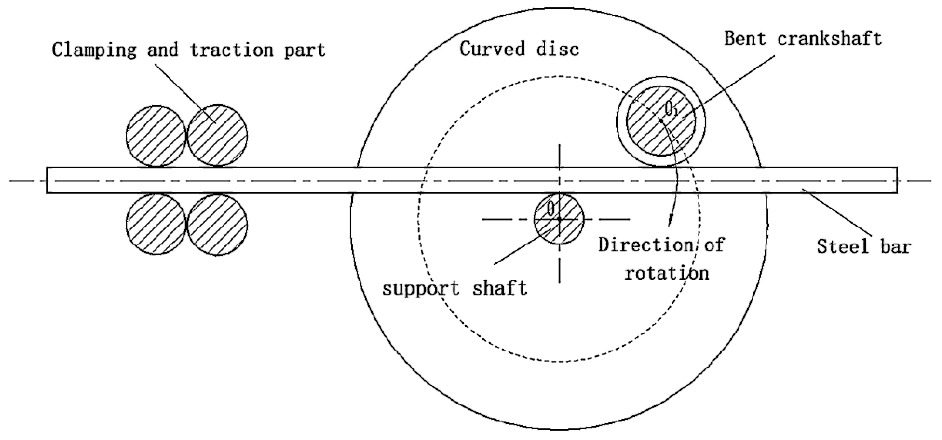
The core mechanism of the steel bar bending machine is the bending mechanism, which is to bend and form the straightened steel bar and bend it into the shape and size required by the building construction by applying a certain size of bending force to the steel bar. Shapes include rectangular stirrups, triangular stirrups, round stirrups, and polygonal stirrups. Common bending processing methods are pressing, rolling, and bending [27]. The working principle of the bending mechanism is simple and the structural form is relatively simple, as shown in Figure 1a, but the processing range is limited by the mold, and when different workpieces need to be processed, the corresponding mold needs to be replaced. The rolling mechanism determines the principle of a circle according to three points and continuously bends the material, as shown in Figure 1b, which is mostly used to process round, arc, elliptical, and parabolic workpieces in shape, and the processing range is small. The bending mechanism is relatively simple; its structure is shown in Figure 1c. One end of the steel bar is fixed by the clamping mechanism, the support shaft supports the steel bar, the bending shaft is fixed on the turntable and rotates with the disc, the steel bar is bent and formed by the pressure exerted by the bending shaft, the steel bar bending angle is controlled by the rotation angle of the bending axis, and now the more mature steel bar bending machines adopt the bending mechanism [28].

Figure 1.
Schematic diagrams of bending mechanisms.
2.2. Bending Deformation Mechanism of Reinforcement
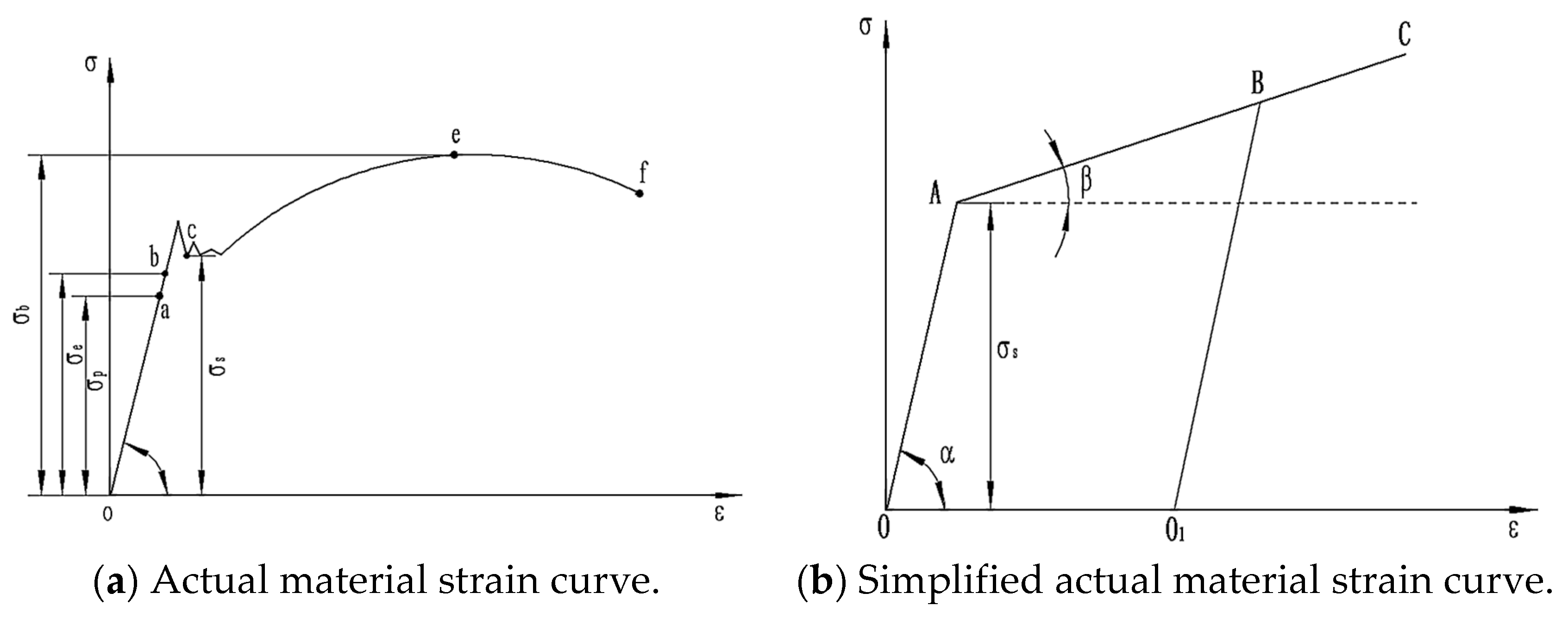
Steel bar bending and forming is a bending forming process that includes both elastic deformation and plastic deformation, which is a more complex elastoplastic deformation. The actual rebar stress change is shown in Figure 2a, and the elastic modulus of the material is . However, the stress change in the rebar needs to be simplified during the simulation analysis, as shown in Figure 2b; in the initial stage, the material mainly undergoes elastic deformation, the stress follows Hooke’s law, the elastic modulus is , the stress–strain will change along the OA, and after the force is removed, the stress–strain will change parallel to the OA [29]. With the increase in external force, when the yield limit is reached, the stress–strain will change along AB, and after the force is removed, the stress–strain will change along BO1, at which time the steel bar will produce plastic deformation. Continue to apply the external force, and when the yield limit is exceeded, the hardening modulus , and the stress–strain will vary along O1BC.

Figure 2.
Stress–strain diagrams of material.
The whole process of steel bar bending is as follows: The initial deformation stage is complete elastic deformation, the maximum stress of the steel bar does not reach the yield limit, the steel bar undergoes small deformation, and after the external force is removed, the deformation can return to the initial state. With the continuous increase in external force, when the stress of the steel bar reaches its yield limit, the steel bar will no longer undergo complete elastic deformation, the steel bar will undergo plastic deformation, and the steel bar cannot return to the initial state after the external force is removed at this stage. In the plastic deformation stage, also known as the elastoplastic deformation stage, the elastic potential energy is released after the external force is removed at this stage, so that the steel bar has a certain springback, but it cannot be restored to the initial state.
3. Optimization of Structural Parameters of Steel Bar Hoop Bending Machine
3.1. Finite Element Simulation and Experimental Analysis
With the continuous development of computer technology and numerical analysis methods, finite element analysis (FEA, finite element analysis) methods have become more and more mature. Because of its advantages of a simple and easy-to-implement algorithm, robust calculation, and no obvious convergence problem, the explicit dynamic analysis method is widely used to solve dynamic problems that occur in a short time, such as blasting, impact, bending deformation, etc., since version 18.0 of the ANSYS Workbench Finite Element Analysis Platform, Display Dynamics Analysis has been made available to designers as a separate module (Explicit dynamics) [30]. Compared to other explicit dynamics software, ANSYS 18.0 software is easy to learn, easy to use, intuitive, convenient, and has an interactive graphical interface. Simulation analysis with ANSYS can significantly reduce workload, increase work efficiency, and reduce labor costs. By automatically defining the contact and fluid–structure interaction interface and default parameters, the working time and workload can be greatly reduced.
3.1.1. Three-Dimensional Model of Bending Mechanism of Reinforcement
The schematic diagram of the bending of the steel bar is shown in Figure 3. The left end of the steel bar is fixed by the clamping mechanism, the support shaft supports the steel bar, the bending shaft is fixed on the original disk and rotates with the disc, the steel bar is bent and formed by the pressure exerted by the bending shaft, and the bending angle of the steel bar is controlled by the rotation angle of the bending axis.

Figure 3.
Schematic diagram of steel bar bending.
In this paper, HRB400 high-strength reinforcement is selected as the reinforcement material, and its material properties are set according to Table 1. Reinforcement materialparameters are added in the ANSYS 18.0 simulation software, and structural steel in the material library is selected for the support shaft and bending shaft.

Table 1.
Model material parameters.
To reduce meshing and computation time, the model needs to be simplified before simulation analysis. During the bending process of the steel bar, only the support shaft and the bending shaft are in contact with the steel bar, so only the support shaft and bending shaft models are established. The clamping part omits its model by imposing a fixed constraint. In order to increase the adhesion between steel bars and concrete, ribbed steel bars are commonly used, but they have no practical effect on the bending of the steel bars, and the steel bars are simplified to smooth cylinders with isotropic homogeneity during simulation. Figure 4 shows the finite element model of the simplified bending mechanism.
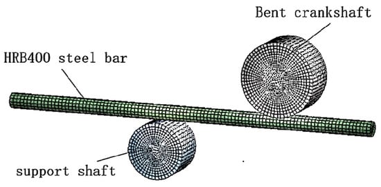
Figure 4.
Finite element model of a steel bar bending mechanism.
3.1.2. Simulation of Steel Bar Bending
In the experiment, an HRB400 high-strength steel bar was widely used in building construction, with an elastic modulus of MPa, a Poisson’s ratio of , and a bending speed of 6.28 rad/s. In order to visually express the influence of various factors on the steel bar, the size and distribution of steel bar stress at the bending angle of 90° were selected for analysis.
- (1)
- The influence of the size of the support shaft on the bending of the steel bar.
According to Table 2, the parametric model was established and the simulation solution analysis was carried out. The diameter D1 of the commonly used support shaft on-site is 10 mm–40 mm, and three different sets of support shaft diameters are used to simulate the steel bar bending process when the support shaft diameter is 20 mm, 30 mm, and 40 mm.
Table 2.
Simulation experiment parameter table.
Figure 5 shows the longitudinal cross-sectional stress distribution of steel bars at 90° bending angle under different support shaft diameters. Steel bar bending springback is the effect of elastoplastic deformation, as shown in the figure; with the increase in the diameter of the support shaft, the stress-distribution surface after bending of the steel bar gradually increases, and the maximum stress value gradually decreases. Therefore, reducing the diameter of the support shaft can effectively reduce the residual stress of the reinforcement. Simulation results show that when the diameter of the support shaft is 20 mm, the stress value is the smallest.
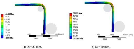
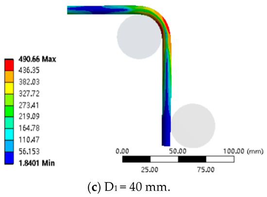
Figure 5.
Stress cloud diagrams of steel bars for different support shaft sizes.
- (2)
- The influence of bending shaft size on steel bar bending.
According to Table 3, the parameter model was established, and the simulation solution analysis was carried out. The diameter D2 of the commonly used bending shaft is 30 mm–70 mm, and three different sets of bending shaft sizes are used to simulate the bending process of steel bars when the bending shaft size is 40 mm, 50 mm, and 60 mm.
Table 3.
Simulation experiment parameter table.
Figure 6 shows the longitudinal-section stress-distribution cloud of a steel bar at a bending angle of 90° under different bending axis sizes. As shown in the figure, with the increase in the diameter of the bending shaft, the stress-distribution surface and the maximum stress value of the steel bar after bending change little, and the three sets of simulation results are basically the same. Therefore, changing the diameter of the bending axis cannot effectively reduce the residual stress of the steel bars.
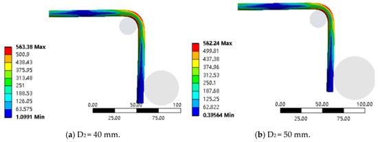

Figure 6.
Stress cloud diagrams of steel bars with different bending shaft sizes.
- (3)
- The influence of the rotation radius of the bending axis on the bending of the steel bar.
According to Table 4, the parametric model was established, and the simulation solution analysis was carried out. The rotation radius R of the commonly used bending shaft is 60 mm–100 mm, and three different sets of bending shaft rotation radii are used to simulate the steel bar bending process when the bending shaft rotation radius is 60 mm, 70 mm, and 80 mm.
Table 4.
Simulation experiment parameter table.
Figure 7 shows the longitudinal-section stress-distribution cloud of a steel bar when the bending angle of the steel bar is 90° under different bending axis rotation radii. As shown in the figure, with the increase in the radius of rotation of the bending axis, the stress-distribution surface of the steel bar does not change significantly after bending, and the maximum stress value gradually increases. Therefore, reducing the radius of rotation of the bending axis can appropriately reduce the residual stress of the steel bar, but the reduction is relatively small. The simulation results show that when the radius of rotation of the bending axis is 60 mm, the stress value is the smallest. However, reducing the radius of rotation of the bending axis will cause a sharp increase in the bending moment.
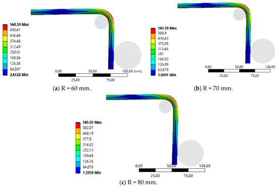
Figure 7.
Stress cloud diagrams of steel bars with different radii of rotation of crankshaft.
The comprehensive simulation analysis results show that both a support axis of 20 mm and a bending axis with a turning radius of 60 mm can reduce the processing stress value of the steel bar. To further verify the relationship between the three parameters and the size of the springback angle, the optimal structural parameters were obtained and on-site experimental analysis was conducted.
3.1.3. Experiment on Springback Angle of Steel Bar Bending
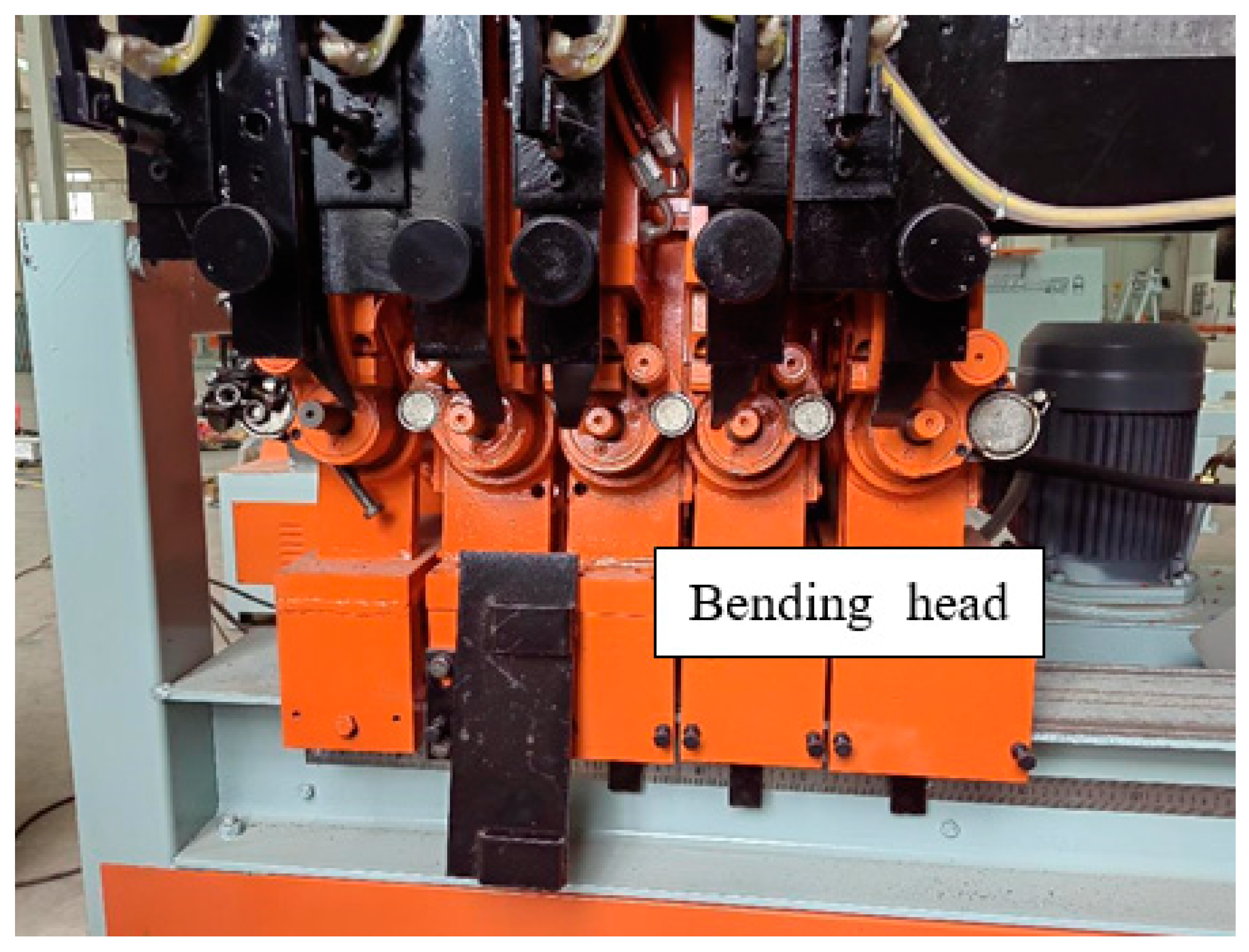
The experimental equipment is the “Giant dragon No. 3” straightening hoop bending integrated machine produced by Hebei Zhijian Machinery Manufacturing Co., Ltd. The company is located in Handan, China. The bending mechanism is shown in Figure 8, and the main technical parameters of the equipment are shown in Table 5.

Figure 8.
Experimental equipment bending mechanism.
Table 5.
Parameters of steel bar bending machine.
The experimental material comprises HRB400 steel bars with a diameter of 10 mm, and the specific parameters are shown in Table 6.
Table 6.
Steel bar material and dimensional parameters.
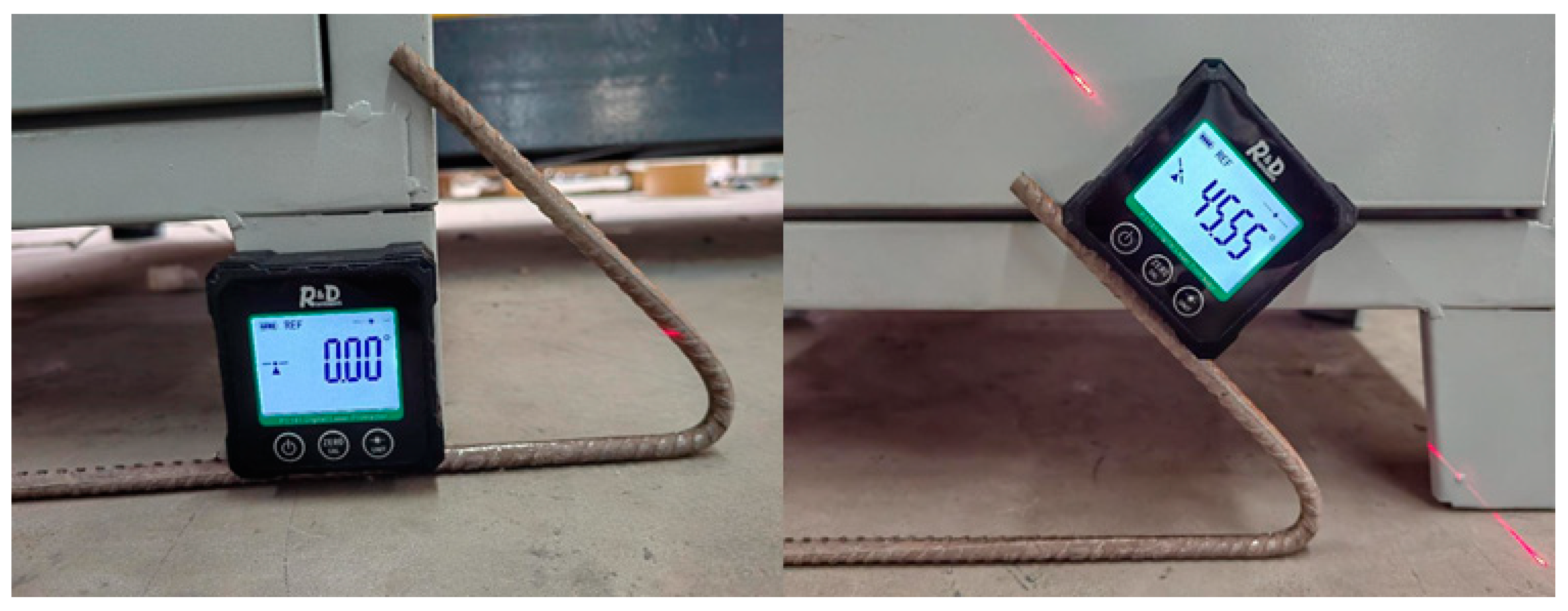
The angle measurement tool adopts the laser angle measuring instrument, and the specific parameters are shown in Table 7.
Table 7.
Laser angle measuring instrument parameter table.
When measuring the angle of the steel bar, the relative measurement mode is selected, one side of the bent steel bar is used as the horizontal line, and the angle of the other side relative to the horizontal line is measured; the measurement method is shown in Figure 9.
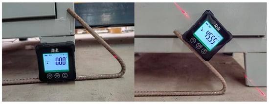
Figure 9.
Steel bar angle measurement.
In order to ensure the accuracy of the obtained parameters, data from 20 springback angles were collected for each angle of different structural parameters, and the average of the springback angles measured 20 times was taken.
- (1)
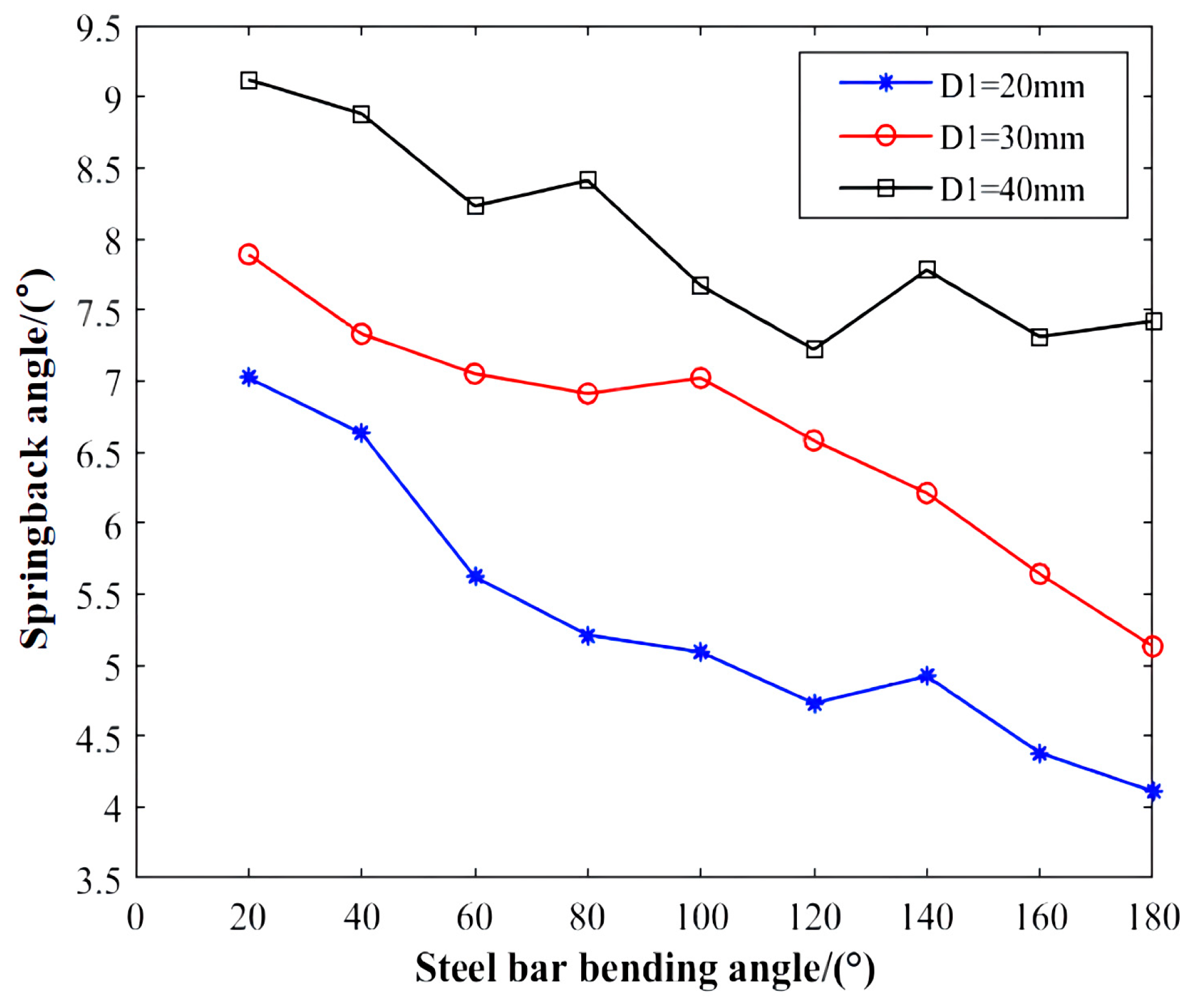
- Influence of support shaft diameter on springback angle.
The steel bar bending experiment is carried out on the straightening hoop bending machine, and the relationship between the steel bar bending angle and the springback angle is obtained as shown in the figure. Figure 10 shows the steel bar springback angle value corresponding to different support shaft diameters D1. As can be seen from the figure, when other structural parameters remain unchanged, the rebar springback angle becomes larger with the increase in the support shaft diameter D1. Combined with the analysis of the simulation results, it can be found that as the diameter D1 of the support shaft increases, the maximum stress of the steel bar bending becomes smaller, the stress distribution becomes wider, and the springback angle becomes larger.
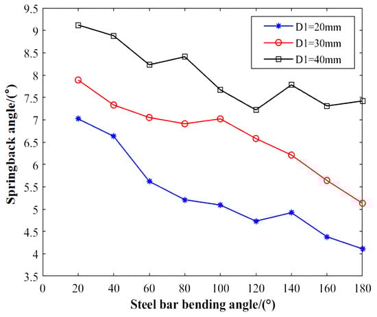
Figure 10.
Springback angle values for different support shaft sizes.
- (2)
- Influence of curved crankshaft diameter on springback angle.
Figure 11 shows the steel bar springback angle values corresponding to different bending shaft sizes D2, and it can be seen from the figure that when other structural parameters remain unchanged, the steel bar springback angle does not change significantly with the increase in bending shaft size D2. Combined with the analysis of the simulation results, it can be found that with the increase in the bending shaft diameter D2, the magnitude and distribution of the bending stress of the steel bar do not change significantly, and the springback angle does not change significantly.
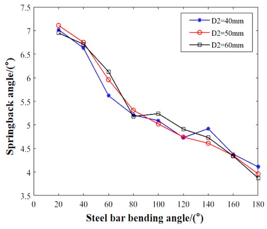
Figure 11.
Springback angle values for different bending shaft sizes.
- (3)
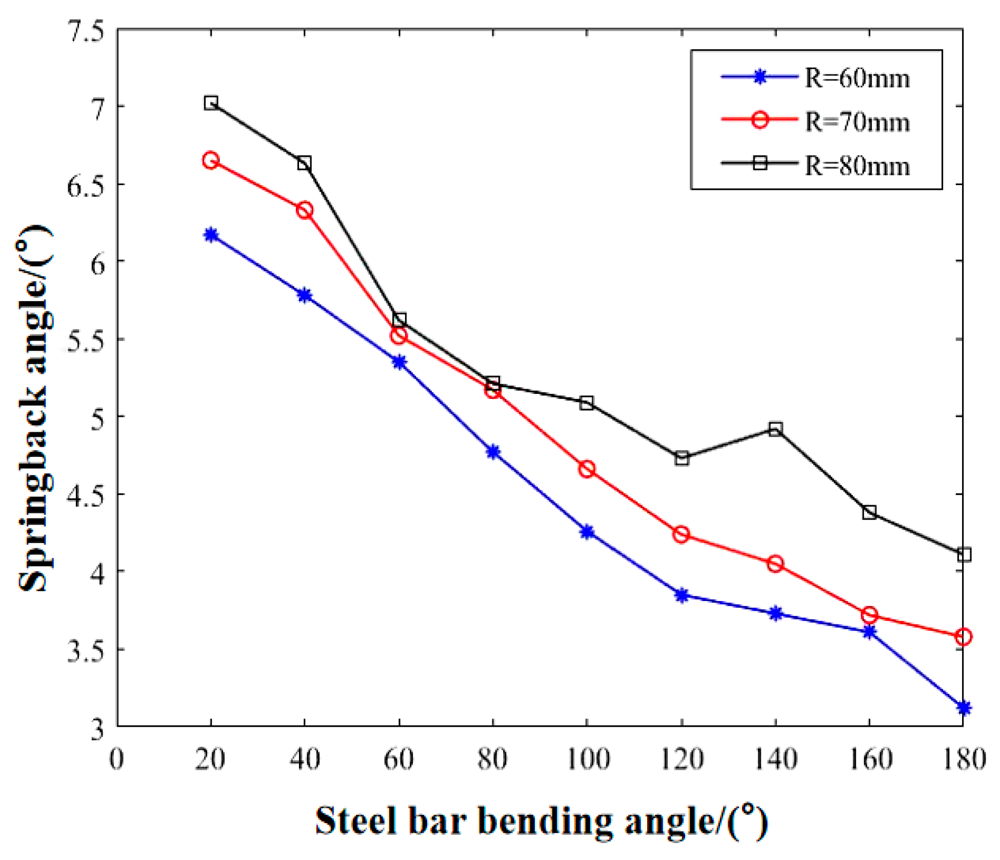
- Influence of bending radius of crankshaft on springback angle.
Figure 12 shows the steel bar springback angle value corresponding to the rotation radius R of different bending axes, and it can be seen from the figure that when other structural parameters remain unchanged, the steel bar springback angle increases with the increase in the bending axis rotation radius R. Combined with the analysis of the simulation results, it is concluded that with the increase in the rotation radius R of the bending axis, the maximum bending of the steel bar becomes larger, the stress distribution does not change significantly, and the bending springback angle increases.
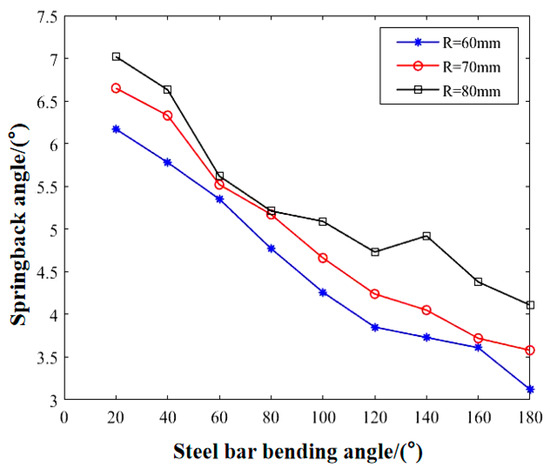
Figure 12.
The value of the springback angle for the rotation radius of the different bending axes.
Through the above simulation results and the springback angle experiment, it is found that the support shaft diameter has a significant effect on the springback angle of steel bar bending. The change in bending shaft diameter has no obvious effect on the bending springback angle of the steel bar. The rotation radius of the bending shaft has a certain influence on the steel bar springback angle, which is not as significant as the support shaft diameter.
3.2. Orthogonal Test
Through the above finite element simulation, the influences of support shaft diameter, curved crankshaft diameter, and bending crankshaft radius on the springback angle of steel bar bending are analyzed, respectively. In order to obtain a set of optimal structural parameters of the bending mechanism, the orthogonal test method was used to test the diameter of the support shaft, the diameter of the bending crankshaft, and the radius of the bending crankshaft. The orthogonal test conditions were as follows: HRB400 high-strength steel bar with common building specifications of 10 mm was selected. The bending angle of the steel bar was 90°. Table 8 shows the level of orthogonal test factors.
Table 8.
The orthogonal experiment factor level table.
3.2.1. Orthogonal Test
According to Table 8, the orthogonal test table of L9(34) with three factors and three levels was selected [31], and a total of nine groups of orthogonal tests were carried out. The orthogonal test table and the springback data of steel bar bending angle are shown in Table 9.
Table 9.
Orthogonal test table.
3.2.2. Analysis of Orthogonal Test Results
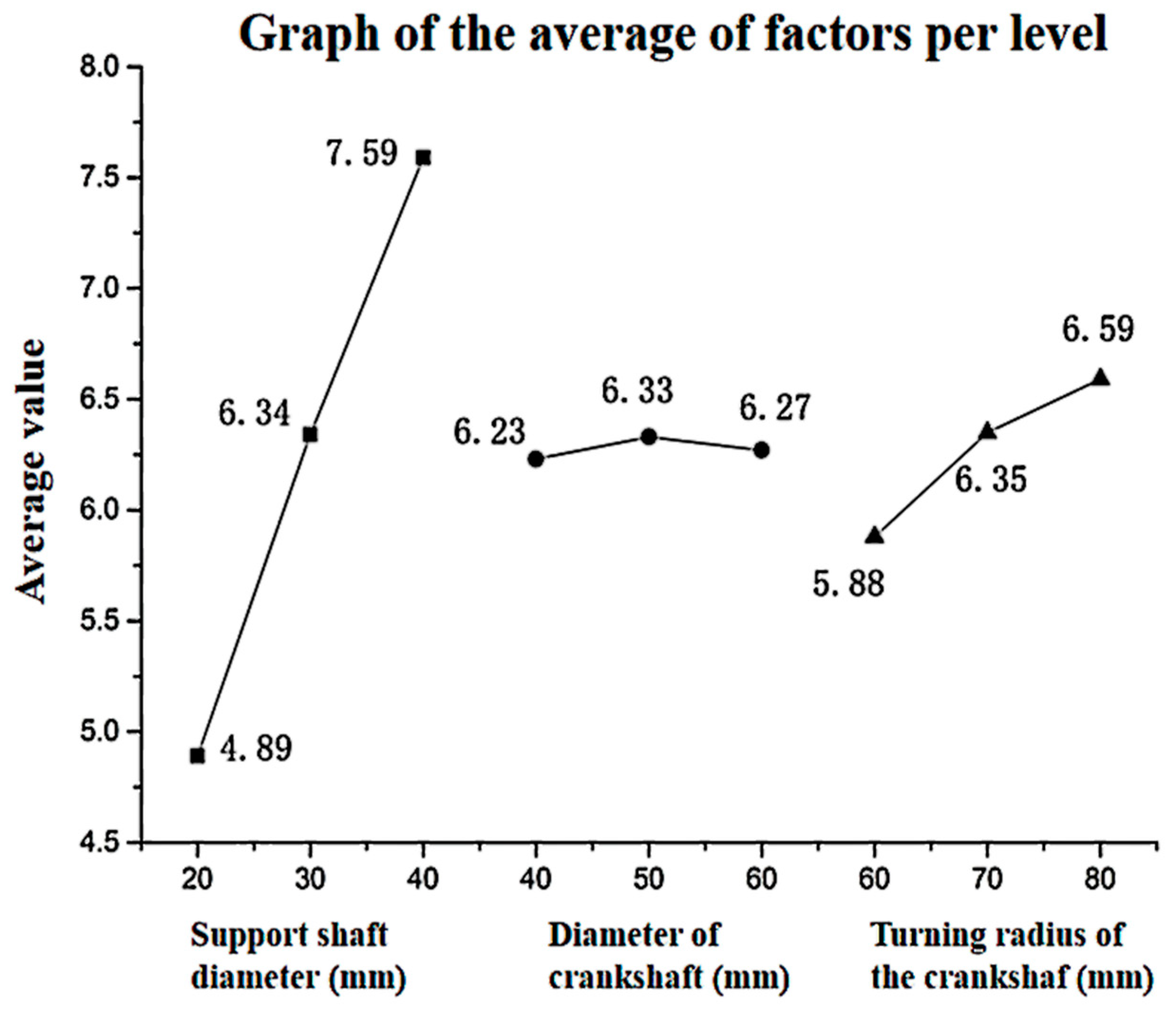
Based on the analysis of the measured springback angle data, the range analysis of the three factors of support shaft diameter, bending crankshaft diameter, and bending crankshaft turning radius is shown in Table 10, and the horizontal mean value of the factors is shown in Figure 13.
Table 10.
Range analysis table.
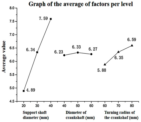
Figure 13.
Plot of the mean of each factor level.
From the above three factors, it can be seen that the larger the value of R, the greater the influence of its corresponding factors on the springback angle. According to Table 10 and Figure 13, it can be seen that the diameter of the support shaft is the optimal factor, followed by the radius of the bending crankshaft and the diameter of the bending crankshaft. Therefore, the advantages and disadvantages of the three factors are as follows: support shaft diameter D1 > bending radius R > bending crankshaft diameter D2. In combination with the optimal level of each factor, it can be seen that the first level of support shaft diameter (20 mm) is the best, the first level of bending crankshaft rotation radius (60 mm) is the best, and the first level of bending crankshaft diameter (40 mm) is the best. However, the smaller the bending radius of the curved crankshaft is, the larger the bending force of the steel bar is, and the more difficult it is to bend the steel bar. Because it is far lower than the influence of the support shaft on the springback angle, the larger bending radius of the crankshaft is taken in practical application. Finally, the bending mechanism parameters are determined as support shaft diameter 20 mm, bending crankshaft diameter 40 mm, and bending crankshaft rotation radius 80 mm. Figure 14 shows the numerical diagram of the elastic angle of reinforcement bending under the optimal structural parameters. Subsequently, the elastic angle compensation formula is solved by taking the hoop bending machine with the structural parameters as the experimental object.
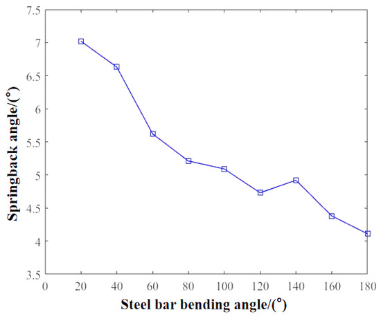
Figure 14.
Steel bar bending springback angle value.
4. Reinforcement Springback Compensation Method
4.1. Theory of Steel Bar Bending Springback
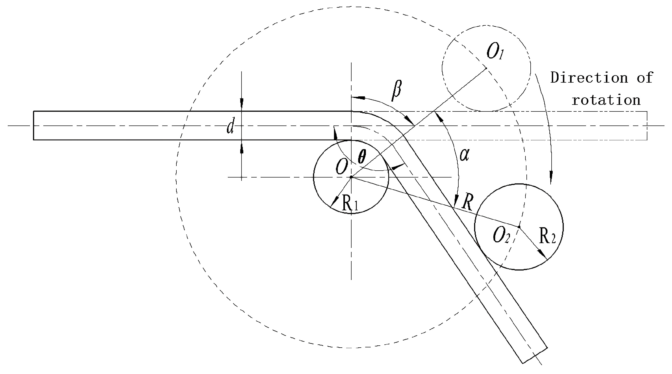
According to the bending mechanism of steel bars, it can be seen that the steel bar is formed by bending mechanism, which is a complicated elastic–plastic bending deformation. Therefore, after the reinforcement is bent, due to the existence of residual stress, the reinforcement will bounce back at a certain angle, and the angle after the springback is the actual bending angle of the reinforcement [32]. The relationship between bending and forming parameters is shown in Figure 15, where is the diameter of steel bar. is the inclination angle of the curved crankshaft and center line; is the radius of rotation of the curved crankshaft; is the radius of the support shaft; is the radius of the bending crankshaft; is the rotation angle of the curved crankshaft, and also, the angles of reinforcement are and ; indicates the bending angle of the steel bar, namely, and .

Figure 15.
Bending angle diagram.
The bending angle of the winding steel bar is controlled by the bending angle of the curved crankshaft. The relationship between the bending angle of the steel bar and the bending angle of the curved crankshaft is as follows:
In order to improve the accuracy of the actual bending angle, the overbending method is used to compensate for the bending springback angle. Figure 16 shows the diagram for the bending springback angle, reinforced bending angle for , reinforced radius of curvature for , and steel angle for . The springback phenomenon occurs after the steel bar bends. The springback angle is , the actual angle of the steel bar becomes , the radius of curvature of the steel bar becomes , and the actual bending angle of the steel bar is .
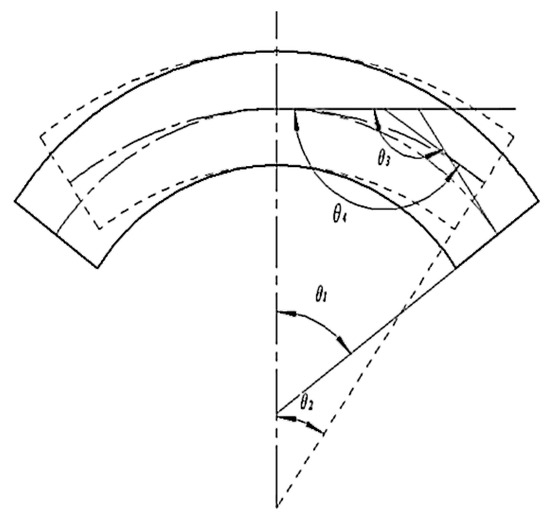
Figure 16.
Schematic diagram of the steel bar bending springback angle.
Reinforcement bending belongs to elastic–plastic bending deformation. According to the principle of “neutral layer unchanged” in reinforcement bending springback [33], it can be obtained as follows:
By combining Equation (1) with Equation (2), the formula for calculating the bending springback angle of the steel bar is shown in Equation (4). However, in the actual application process, the steel bar needs to be straightened, hoop bent, cut, and other processing processes. After several elastic–plastic deformations, the steel bar will produce work hardening [34]. Work hardening will lead to a reduction in plasticity and toughness of steel bars. Therefore, in practical application, because the influence of work hardening on the springback angle is considered, the theoretical formula cannot obtain the exact value of the springback angle. Therefore, in the processing of steel bars, the method of springback angle compensation is often used to control the accuracy of the steel bar bending angle.
4.2. Bending and Springback Compensation Method
4.2.1. Classical Springback Compensation Method
- (1)
- Empirical data table compensation method.
In long-term processing and use, list the springback data according to the experience, establish the query table, and when there are corresponding data in the database, you can refer to the springback compensation [35]. However, this compensation method has some disadvantages such as heavy workload, long period of accumulated experience values, and small precision. Table 11 shows the data table of steel bar springback experience of an enterprise.
Table 11.
Steel bar springback experience data sheet.
- (2)
- The compensation method of EATONLEONAD Company in the United States.
In the process of bending a batch of steel bar materials, under the condition that the technical parameters of the hoop bending machine have been determined, it can be considered that the bending angle of the steel bar is linearly related to the forming angle after springback. This method can effectively solve the springback problem of the steel bar in bending [36]. The formula is as follows:
Although the above two methods have been applied in practice, the actual springback angle value is affected by materials and equipment structure and other factors; therefore, the relationship between the bending angle and the forming angle after springback is not strictly linear. The springback angle compensation formula needs to be determined according to the actual situation during processing. This paper uses the numerical analysis method to obtain the springback angle compensation formula with higher accuracy.
4.2.2. Numerical Analysis Method
- (1)
- Least square method.
The least square method seeks the best function matching of data by minimizing the sum of squares of errors. The least square method can easily obtain unknown data and minimize the sum of squares of errors between the obtained data and the actual data. When used as an interpolation method, the least square method can also be used for curve fitting [37]. The theory of the least square method is simple, and the calculation is small. Even though the use of cubic spline curve or RBF (radial basis function) for curve fitting is popular today, the least square method is still widely used in polynomial curve or line fitting problems.
When the least square method is used to solve the fitting curve function, the form of needs to be determined by observation, as follows:
Among them, is the stay constant, and is determined by observations of functional form.
Using the least square method, the mode of matching function selected is very important. If the discrete data show exponential variation law, the mode of matching function in exponential form should be selected; if it shows the polynomial variation law, the mode of matching function in polynomial form should be selected. If the mode selected is wrong, the fitting effect will be poor. This is also an area that needs special attention when using the least square method for curve fitting.
- (2)
- Newton polynomial interpolation method.
Polynomial interpolation is also widely used in data analysis and curve fitting. Most practical problems require the function to represent some kind of law. However, the practical problems are relatively complicated and there are many influencing factors. In the actual process, only a series of scattered points in a certain interval can be obtained. In order to be studied, these scattered points need to be fitted to the corresponding curve so that an accurate functional relation can be obtained [38]. However, it is difficult to obtain the exact functional relation , so a simple functional relation is usually used to replace it, and is required to be valid for , 2, …, n, as shown in Figure 17.
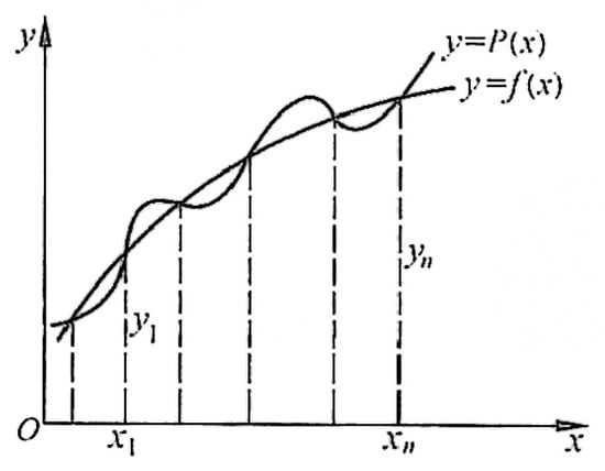
Figure 17.
Function graph.
The interpolation polynomial solved by the Newton interpolation method satisfies , and the interpolation polynomial solved is in the following form:
where is the average difference of order of function .
- (3)
- The cubic spline interpolation method.
Spline interpolation is a kind of interpolation method commonly used in industrial design to obtain smooth curves. Among all the interpolation functions that can ensure convergence and stability, the most commonly used and the most important interpolation function is the spline interpolation function. Interpolation curves and surfaces calculated by spline function have been widely used in the design of precision machinery such as aircraft, ships, and automobiles [39]. The cubic spline is one of the most widely used ones. Using the cubic spline curve for curve fitting can obtain very-high-precision fitting results and easy-to-obtain fitting functions.
Cubic spline interpolation curve fitting was carried out using the experimental data collected above. Using Matlab R2018a mathematical operation software to solve. The cubic spline interpolation function obtained by the solution is generally written in the form of the three-moment equation:
In Equation (8), represents the bending angle of the reinforcement, represents the average springback angle of the reinforcement, represents the wheelbase separation of two adjacent data points, and represents the second derivative of the function.
4.3. Solve the Springback Compensation Formula
- (1)
- Data collection.
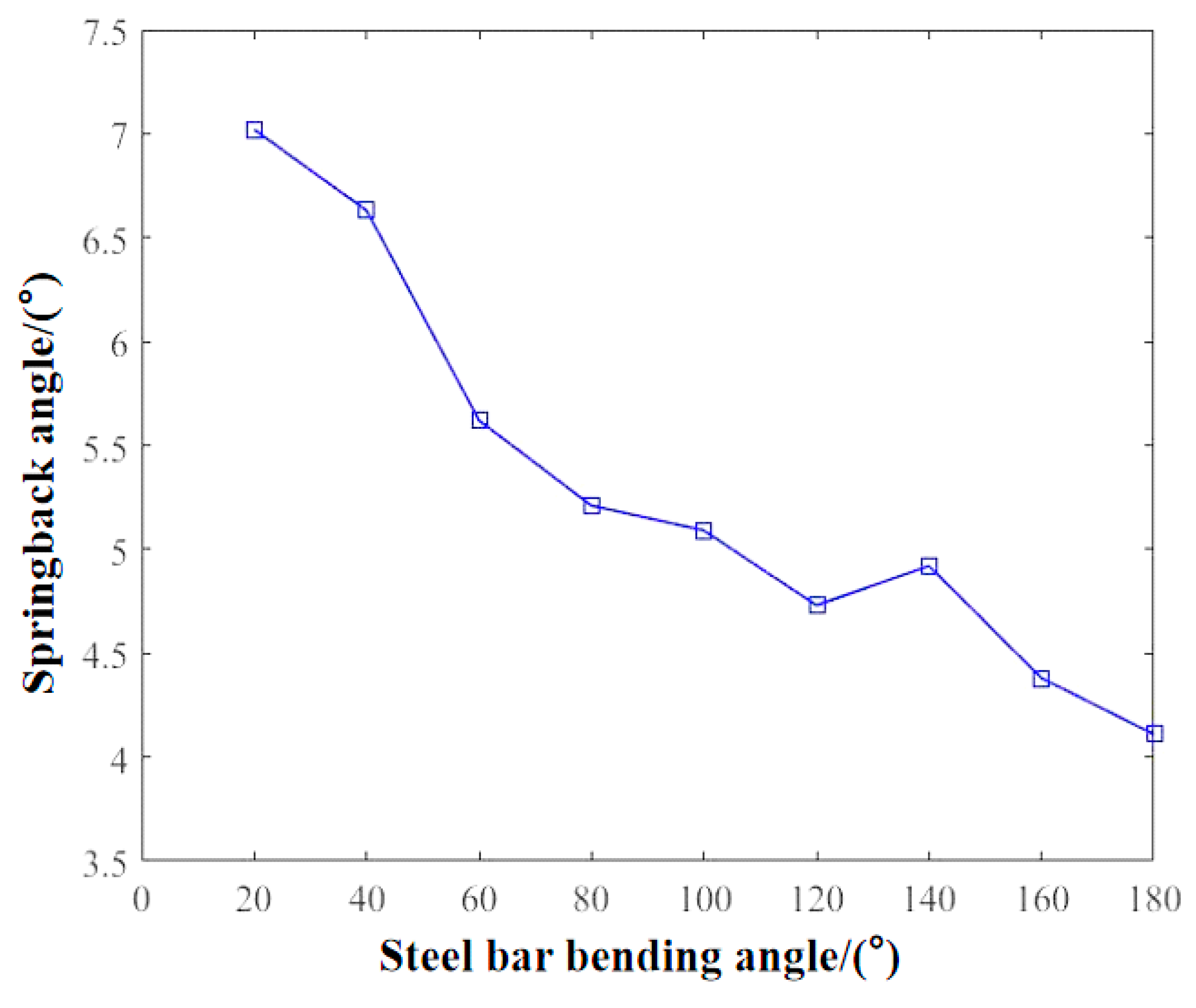
The bending angle of steel bars used in construction ranges from 0° to 180°. In this paper, an integrated steel bar straightening and bending hoop machine is used to conduct bending experiments of steel bars at 9 angles of 20°, 40°, 60°, 80°, 100°, 120°, 140°, 160°, and 180°, respectively, to measure the springback angle. In order to ensure the accuracy of the parameters obtained, the springback angle data were collected 20 times for each angle, and the average value of the bounce angle measured 20 times was taken. The collected data is shown in Table 12.
Table 12.
Steel bar bending angle and springback angle.
- (2)
- Solve the fitting curve function.
Matlab mathematical software was used to solve the problem, and the expressions of least square linear fitting function , least square fitting function , Newton interpolation polynomial , and cubic spline interpolation function were, respectively,
- (3)
- Draw the fitting curve.
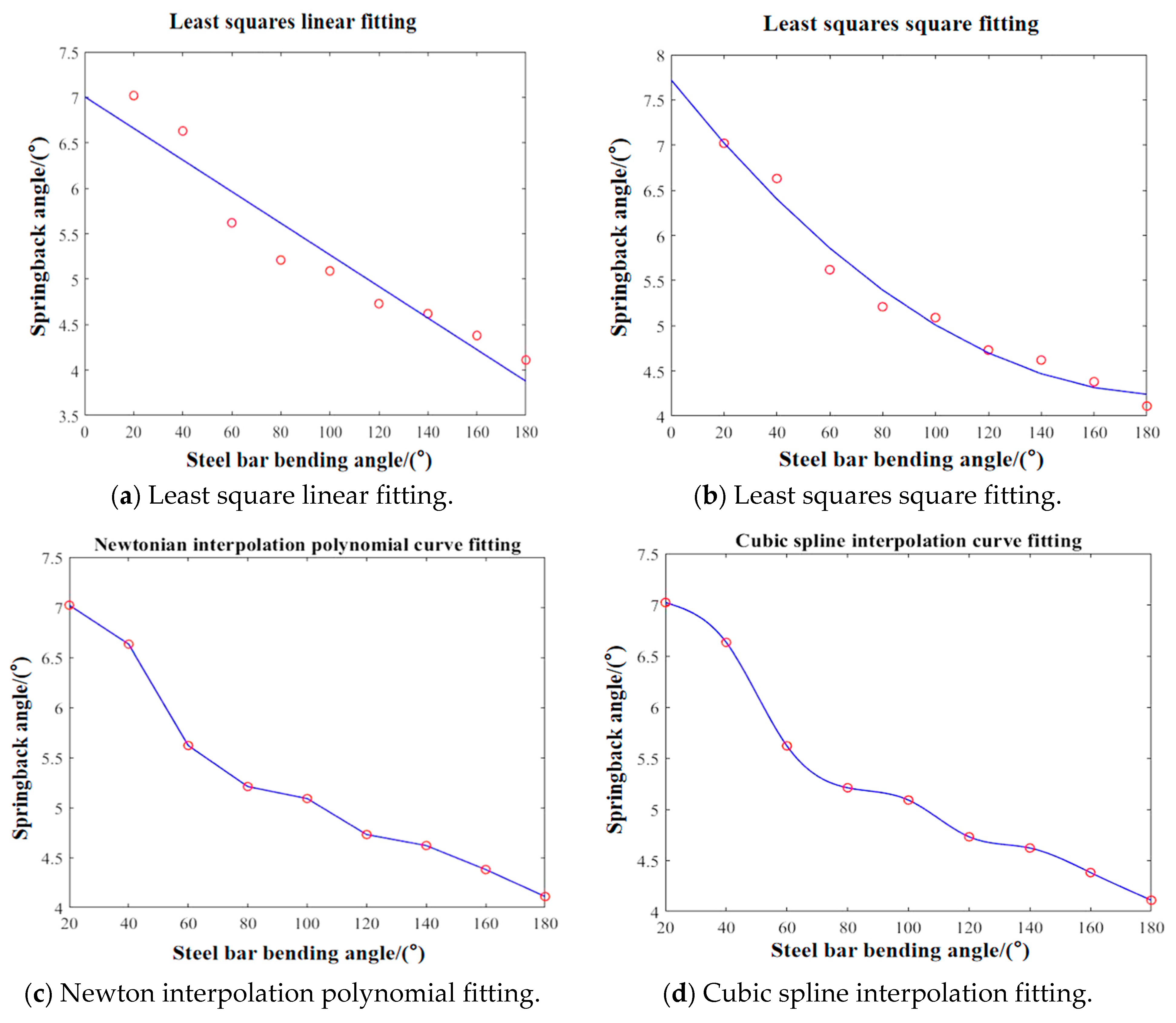
Through the fitting curve function relation solved above, the curves of least square linear fitting function , least squares square fitting , Newton interpolation polynomial , and cubic spline interpolation function are drawn, respectively, to observe the fitting effect.
According to the observations in Figure 18, it is found that the accuracy of curves obtained by the least square linear fitting method and square fitting method is worse than that obtained by the Newton interpolation polynomial method and cubic spline interpolation method. The fitting curves obtained by the Newton interpolation polynomial method and cubic spline interpolation method all pass through scatter points, and the fitting curves obtained by the cubic spline interpolation method are smoother than those obtained by the Newton interpolation polynomial method.
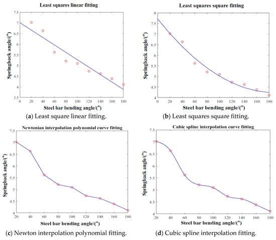
Figure 18.
Each fitting method corresponds to the fitting curve.
4.4. Experimental Verification and Analysis
In order to verify the accuracy of the compensation formulas obtained by the four numerical methods, the equipment was used again to collect the springback angles of the steel bar when it was bent at 30°, 45°, 90°, 135°, and 150°, and the average values were collected for several repetitions. Then, each bending angle was substituted into the fitting functions , , , and ; the springback angles obtained from each compensation formula are shown in Table 13.
Table 13.
Table of springback angle parameters of different fitting curves.
By comparing the error between the bending springback angle of each fitted curve and the actual bending springback angle, Table 14 is compiled. The data in the table reflect the accuracy of each fitting curve.
Table 14.
Parameter error table of springback angle of different fitting curves.
By comparing the errors between the springback angle obtained by four different steel bar bending springback compensation formulas and the actual springback angle, it was found that the accuracy of the springback compensation formula obtained by the least squares method is significantly poorer. The springback compensation formula obtained by the Newton interpolation polynomial has the same error as the springback compensation formula obtained by the cubic spline interpolation method at bending angles of 30° and 90°, but the error of the springback compensation formula obtained by the cubic spline interpolation method at other angles is lower.
In summary, the cubic spline interpolation method has higher curve fitting accuracy, and the springback angle compensation formula obtained can effectively improve the accuracy of the steel bar bending angle, providing a more accurate springback compensation method for steel bar processing.
5. Conclusions
In this paper, the following conclusions are obtained to improve the accuracy of the bending angle of steel bars:
- (1)
- The mechanism of steel bar bending and forming was studied, and the effects of support shaft diameter, bending shaft diameter, and bending shaft rotation radius on steel bar springback angle were analyzed by ANSYS explicit dynamics simulation and field experiments, and then the bending structure parameters were optimized by orthogonal test method, and finally the structural parameters were 20 mm support shaft diameter, 40 mm bending shaft diameter, and 80 mm bending shaft rotation radius, which could effectively reduce the steel bar springback angle and improve the accuracy of the steel bar bending angle after bending.
- (2)
- This article innovatively proposed the cubic spline interpolation method to solve the compensation formula for the steel bar bending springback angle. The accuracy of the springback angle compensation formula obtained by the least squares linear fitting method, Newton interpolation polynomial method, and cubic spline interpolation method was compared. The results show that the cubic spline interpolation method has high fitting curve accuracy and can effectively improve the accuracy of the steel bar bending angle.
- (3)
- This article focuses on parameter analysis and optimization of the bending mechanism of the steel bar bending machine, and the research has limitations. Different bending mechanism structures and processed steel bar diameters can have an impact on the springback angle, so this springback compensation formula is only applicable to the current structure and 10 mm steel bar bending processing. Subsequent research needs to take into account the actual situation, taking into account the structural parameters and steel bar diameter and using the cubic spline interpolation method to solve the springback compensation formula.
- (4)
- In view of the problem of steel bar bending and springback, follow-up research can consider using deep learning methods to build a model to train the springback angle data in order to achieve independent control and automatic compensation of the springback angle, improve the accuracy of the steel bar bending angle, and realize intelligent rebar processing.
Author Contributions
J.R.: Formal analysis, Funding acquisition, Investigation, Methodology, Formal analysis, Supervision and Writing—review and editing. J.W.: Methodology, Software, Validation, Writing—original draft, Formal analysis, and supervision. Z.Z.: Formal analysis, Software, Validation, and Visualization. Y.X.: Funding acquisition, Formal analysis, Validation, Data management, Investigation, Writing—review and editing. All authors have read and agreed to the published version of the manuscript.
Funding
This research received no external funding.
Institutional Review Board Statement
Not applicable.
Informed Consent Statement
Not applicable.
Data Availability Statement
Data sharing not applicable.
Conflicts of Interest
The authors declare no conflict of interest.
References
- Wang, L.W.; Shen, X.B.; Pan, C.M.; Tang, W.G.; Zhang, X.H. Technical Status and Improvement Direction of Domestic Steel Bar Bending Machine. J. Zhengzhou Univ. Light Ind. (Nat. Sci. Ed.) 2010, 25, 37–40. [Google Scholar]
- Hou, A.S. Analysis of Steel Bar Straightening and Bending Equipment. J. Constr. Mech. 2014, 35, 54–56. [Google Scholar]
- Liang, X.J.; Bi, C. Difficulties and Treatment Measures of Numerical Control hoop Bending Machine in large-scale engineering. J. Build. Constr. 2014, 36, 71–73. [Google Scholar]
- Wang, L.W.; Wu, Y.; Ma, J.T.; Zhao, J.Y. GWG20 Type Automatic Angle Steel Bar Hoop Bending Machine. J. Constr. Mach. 2006, 15, 96–97. [Google Scholar]
- Liu, L. Design and Implementation of CNC System of 5/12 Automatic Steel Bar Hoop Bending Machine. Ph.D. Thesis, Yanshan University, Qinhuangdao, China, 2011. [Google Scholar]
- Chen, K.Y. Research on Forming Mechanism and Simulation of Steel Straightening and Cutting Bending Hoop. Ph.D. Thesis, Yanshan University, Qinhuangdao, China, 2014. [Google Scholar]
- Yang, L. Design and Research of Control Platform for Hoop Bending Machine Based on μC/OS-II. Ph.D. Thesis, Xi’an University of Architecture and Technology, Xi’an, China, 2016. [Google Scholar]
- Yuan, Z.P. Parameter Analysis and Simulation of Double Bending Hoop Die. Ph.D. Thesis, Yanshan University, Qinhuangdao, China, 2016. [Google Scholar]
- Jiang, Y.; Cheng, X.; Li, H.; Ren, X.; Li, Y. Structural Design of Steel Bar Bending Machine. J. Phys. Conf. Ser. 2021, 1986, 012097. [Google Scholar] [CrossRef]
- Xiao, W.H.; Chen, Q.T.; Zhu, W.Q. Research and Development Key Technologies of Pure Hydraulic Five-head Steel Bar Hoop Bending Machine. J. Putian Univ. 2021, 28, 66–70. [Google Scholar]
- Sasikala, R.; Rakshana, M.; Thinaa, T.; Thirupponvel, P.; Vasanth, D. Automatic Bar Bending Machine using Pneumatic System. Int. J. Innov. Technol. Explor. Eng. (IJITEE) 2020, 5, 9. [Google Scholar] [CrossRef]
- Zhou, Z.Y.; Zhu, M.Q.; Zeng, G.C.; Liu, X.B.; Zhong, L.P. Design and Simulation Analysis of a New Steel Bar Bending Mechanism. J. Mach. Tool Hydraul. 2023, 51, 136–140. [Google Scholar]
- Xu, C.Y. Metal Plastic Forming Theory; Metallurgical Industry Press: Dongcheng, China, 2009. [Google Scholar]
- Gu, R.J.; Yang, H.; Zhan, M.; Li, H.; Zhang, X.G. Research Progress of Springback in Bending Forming. J. Mech. Sci. Technol. Aerosp. Eng. 2005, 6, 653–658. [Google Scholar]
- Zhang, Z.S. Calculation of Bending Adjustment Value of Reinforced Round Steel Based on Neutral Layer Principle. J. Sci. Technol. Innov. 2023, 3, 75–77, 81. [Google Scholar]
- Yan, S.L.; Du, S.Y. Mechanical Management and Development. J. Mech. Manag. Dev. 2010, 25, 68–69. [Google Scholar]
- Cai, W.; Shuang, Y.H.; Gou, Y.J.; Mao, F.L. Study on large curvature coreless bending springback of 0Cr18Ni9 pipe. Chin. J. Plast. Eng. 2018, 25, 70–76. [Google Scholar]
- Zheng, X.J.; Li, Y.P.; Chang, X.H. Influence Factors and Correction of Springback Angle of Steel Bar Bending. J. Constr. Mech. 2014, 35, 59–61. [Google Scholar]
- Shang, Z.P.; Liu, Z.L.; Chen, K.Y. Research on Springback Angle and Stirrup Accuracy of High Strength Steel Bar Bending. J. Forg. Stamp. Technol. 2017, 42, 155–160. [Google Scholar]
- Zhu, C.Q.; Shu, J.J. Experimental Study on Influencing Factors of Springback of 1Cr18Ni9Ti Tube. J. Technol. Mark. 2016, 23, 105–106. [Google Scholar]
- Chen, H.; Jia, C.X.; Niu, Y.P.; Wang, L.X. Simulation Analysis on Springback of 980 MPa High Strength Steel. J. Hebei Metall. 2020, 12, 40–42. [Google Scholar]
- Guo, L.; Zhang, M.G.; Liu, D.H.; Li, Y.B.; Xu, F.; Wu, C.H.; Zhang, Z.; Liu, L.G. Analysis of Influencing Factors on Springback of 1500 MPa Ultra-High Strength Martensitic Steel. J. Yanshan Univ. 2022, 46, 22–28. [Google Scholar]
- He, X.; Ma, J.; Tronvoll, S.A.; Welo, T. In-Process Monitoring of Springback in Industrial Bending Using a Laser Sensor-Based Method. J. Key Eng. Mater. 2022, 926, 2266–2274. [Google Scholar] [CrossRef]
- Ma, R.; Ma, C.; Zhai, R.; Zhao, J. Research on Control Technology of Variable Curvature Bending Springback Based on Iterative Compensation Method. J. Int. J. Precis. Eng. Manuf. 2022, 23, 489–501. [Google Scholar] [CrossRef]
- Wang, Z.; Lin, Y.; Qiu, L.; Zhang, S.; Fang, D.; He, C.; Wang, L. Spatial variable curvature metallic tube bending springback numerical approximation prediction and compensation method considering cross-section distortion defect. Int. J. Adv. Manuf. Technol. 2021. prepublish. [Google Scholar] [CrossRef]
- Wu, P.; Zhang, Y.; Huang, X.; Lu, G. Finite Element Analysis of Bending Springback of L-Shaped Parts Based on Dynaform. J. Die Mould. Manuf. 2016, 16, 18–21. [Google Scholar]
- Zhou, Y.P. Research on Technological Parameters of Pipe and Profile Flexible Bending Forming. Ph.D. Thesis, Jilin University, Changchun, China, 2018. [Google Scholar]
- Zhao, X.H.; Hou, A.; Ji, E.L.; Yue, W.W. Analysis of Steel Bar Bending Forming Technology. J. Constr. Mech. 2014, 35, 84–85. [Google Scholar]
- Zhang, P.; Wang, C.J.; Zhu, Q. Basic Theory and Analytical Application of Elastic-Plastic Mechanics; Harbin Institute of Technology Press: Harbin, China, 2020. [Google Scholar]
- Ding, J.B. ANSYS Workbench 18.0 Finite Element Analysis Case Description; Tsinghua University Press: Beijing, China, 2019. [Google Scholar]
- Men, M.J. Analysis on Influencing Factors of high-rise building deformation based on Orthogonal Test. J. Shandong Coal Sci. Technol. 2022, 40, 167–171. [Google Scholar]
- Xue, K.M.; Chen, L.; Kong, Y.; Li, P.; Huang, B.; Li, C.J. Numerical Simulation and Experiment on CLAM Springback. J. Plast. Eng. 2013, 20, 53–57. [Google Scholar]
- Feng, X.J.; Liu, S.F.; Yang, F.J. Mechanics of Materials; Beijing Institute of Technology Press: Beijing, China, 2021. [Google Scholar]
- Zhou, C.L.; Liu, H.M.; Bai, J.G.; Nie, Z.S.; Zhou, H.F.; Qiao, J.W. Effect of Cold Rolling Deformation on Mechanical Properties of 304 Stainless Steel. J. Iron Steel 2012, 47, 70–75. [Google Scholar]
- Sun, C.H.; Yang, Y. Calculation of Bending Adjustment Values of Different Angles in Steel Bar Cutting. J. Constr. Technol. 2018, 47, 377–380. [Google Scholar]
- Papeleux, L.; Ponthot, J.P. Finite element simulation of springback in sheet metal forming. J. Mater. Process. Technol. 2002, 125, 785–791. [Google Scholar] [CrossRef]
- Chen, L.B.; Zheng, Y.Q. Study on Curve Fitting Based on least square Method. J. Wuxi Vocat. Tech. Coll. 2012, 11, 52–55. [Google Scholar]
- Li, Q.Y.; Wang, N.C.; Yi, D.Y. Numerical Analysis; Tsinghua University Press: Beijing, China, 2008. [Google Scholar]
- Hai, X.; Zhu, Z.J. Comparative analysis of colorimetric temperature measurement error correction by least square method and Cubic Spline curve fitting. Laser J. 2015, 36, 72–76. [Google Scholar]


Disclaimer/Publisher’s Note: The statements, opinions and data contained in all publications are solely those of the individual author(s) and contributor(s) and not of MDPI and/or the editor(s). MDPI and/or the editor(s) disclaim responsibility for any injury to people or property resulting from any ideas, methods, instructions or products referred to in the content. |
© 2023 by the authors. Licensee MDPI, Basel, Switzerland. This article is an open access article distributed under the terms and conditions of the Creative Commons Attribution (CC BY) license (https://creativecommons.org/licenses/by/4.0/).