1. Introduction
Hydraulic pumps [
1] have received considerable attention in recent years because of their strategic importance and economic value [
2]. This tendency has encouraged the community to shift its research focus to issues connected to hydraulic pumps [
3]. This transition entails not only theoretical investigation [
4], but also actual application of hydraulic control systems, particularly the creation of valve control systems [
5]. Valves, particularly proportional [
6] and other types of valves, are critical components of the complete hydraulic control system. Stringent constraints [
7] are placed on the dynamic [
8] performance of the valves as well as the accuracy of the sensor feedback in order to meet the requirements of high precision [
9], high response, and high robustness. This means that when developing and producing valves [
10], every detail must be considered to assure their stability and dependability [
11]. Simultaneously, the variable mechanism of the variable pump plays a significant role in enhancing pump flow response. Flow regulation can be made faster and more exact by optimizing and upgrading the variable mechanism [
12].
However, improving the control system of the variable mechanism of swashplate axial piston pumps remains a difficult research topic at the moment [
13]. This necessitates a thorough examination of the hydraulic system’s dynamic properties as well as the investigation of new control algorithms and approaches [
14]. At the same time, the effects of numerous parameters in the actual working environment, such as variations in temperature, pressure, and fluid viscosity, on system performance [
15] must be considered [
16]. Only through continual study and innovation can the efficiency and reliability of the swashplate axial piston pump [
17] variable mechanism’s control system be improved to satisfy the ever-changing engineering needs [
18].
Zhu et al. [
19] created a control system for a servo variable pump in their investigation. They investigated the effectiveness of two control approaches in their study: conventional PID control and fuzzy PID control. The study’s simulation findings showed that the fuzzy PID controller outperformed the traditional PID controller in terms of system performance and efficiency. These findings illustrate the benefits of using fuzzy logic to control the servo variable pump, as it provides better responsiveness and robustness than the typical PID control strategy. Qian Sujuan et al. [
20] undertook research with the goal of improving the control precision of electro-hydraulic proportional valves by merging a unique fuzzy algorithm with a PID controller. They used AMESim and Simulink software to run joint simulations to test the effectiveness of their suggested strategy. Their simulation findings demonstrated that this strategy significantly optimized the system’s frequency response and increased the stability of spool displacement. These findings add to the expanding body of knowledge about enhanced control strategies for electrohydraulic systems. Postlethwaite et al. [
21] provided constrained optimization for a better understanding of the selection principle of the weighting function, which is constructed so that incorrect and unstable weights are not used to describe the effect of weights on different design purposes. The literature [
22] demonstrates and proves that single-input and single-output weighting functions can be used to design controllers with hybrid sensitivity control with only minor design process modifications. QingGuo et al. [
23] designed a simplified robust controller based on the solution of the suboptimal control problem for enhancing the structural stability of electro-hydraulic servo systems (EHSSs) with uncertain parameters. By integrating sliding mode control and robust control methods, to improve the speed control performance of PMSM systems, Zhang X et al. [
24] introduced the speed-mode reference learning (SMRL) method. This dynamic technique responds to changes in the system while maintaining excellent tracking performance. Experiments and simulations indicate its ability to dramatically cut system reaction time. In terms of handling parameter fluctuations and load disruptions, the SMRL method beats conventional strategies. It provides stable and accurate control, improving system efficiency and stability. The experimental results confirm its efficacy. Overall, the SMRL approach contributes significantly to control systems, helping applications such as robots, electric vehicles, and industrial automation.
This paper proposes to model and simulate the control system of the variable mechanism of the axial piston pump using the simulation technique of robust control. Simulink is used to model the control system parts separately in order to establish a more realistic and reliable model, which can reduce the cost and increase the design efficiency in comparison to an actual physical experiment. Starting with PID control, the effect of this control is evaluated in connection with the degree of stability of the PID for the research of variable mechanism control of axial piston pumps. In this paper, we examine the control system of the variable mechanism of an axial piston pump, design the robust controller by applying the theory, and investigate its ability to assure motion accuracy in the presence of an external load disturbance; solenoid valves improve the integration of the hydraulic system and control, as well as the electrical impulses from sensors and control signals.
2. Control System Composition Principle and Description
A swashplate axial piston variable pump is the type of variable pump being explored. This type of pump is used in hydraulic systems due to its adaptability and efficiency. It works on the swashplate mechanism, in which the angle of the swashplate affects the displacement of the pistons and, as a result, the flow rate of the pump. Furthermore, the swashplate axial piston variable pump is a four-quadrant pump, referring to its ability to operate in four separate operating situations or quadrants. The combination of positive/negative flow and positive/negative pressure defines these quadrants. Positive flow and positive pressure, negative flow and positive pressure, or negative flow and negative pressure can all be generated by the pump. The variable pump’s capacity to work in all four quadrants provides more flexibility and adaptability in a variety of hydraulic applications. It can deal with a variety of load requirements, reverse flow events, and even energy recovery scenarios. As a result, the swashplate axial piston variable pump is an excellent solution for a variety of industrial and mobile hydraulic systems [
25].
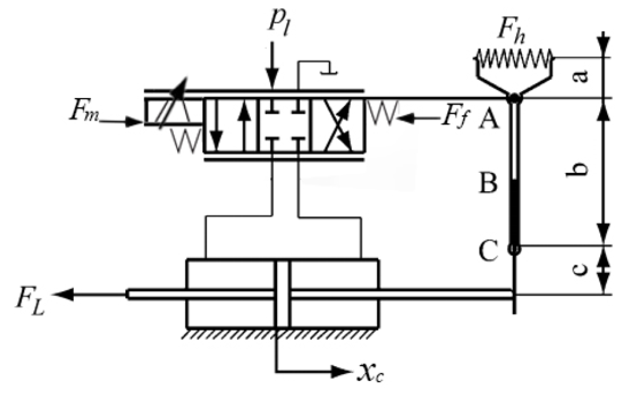
An axial piston pump is seen schematically in
Figure 1. The control system, as illustrated in
Figure 2, employs a typical hydraulic valve to regulate the closed-loop control of the inflow volume, with an angle sensor determining whether normal operating conditions have been met.
The diagram depicts the operation of the variable pump control system [
23]. Sensors detect and recognize the position of the piston in the variable cylinder. The controller algorithm changes the direction of the force delivered to the proportional directional valve by adjusting the output drive current of the proportional solenoid based on the detected position information.
When the proportional reversing valve is pushed to the left, hydraulic fluid enters the piston and pushes it to be displaced, causing the L4VG variable pump to change. Through the pull fork, the piston returns a force to the proportional directional valve, causing the spool to reset.
After the proportional directional valve’s spool returns to zero, the spool can be in a balanced state when the size of the current signal input force received by the proportional directional valve equals the force generated by the feedback spring, forming a closed-loop system of feedback control of the piston position.
Because the swashplate and variable cylinder of the L4VG variable pump are mechanically connected, any change in variable piston position will result in a change in swashplate inclination.
As a result, the variable mechanism displacement of the variable pump changes after an operational procedure [
26]. This mechanism change can be performed by combining it with feedback control of piston position to produce accurate control and regulation of the hydraulic system to fulfill the needs under various working situations.
The variable pump may alter and adapt to the working conditions of the hydraulic system during the working process using this closed-loop control system based on the real application requirements.
Mathematical Modeling of the Variable Mechanism of L4VG Variable Pump
A proportional directional valve is the core component of the servo control system; its proportional solenoid can accept the electrical signal and convert it into a mechanical signal, while generating electromagnetic force
, because the thrust of the proportional solenoid is proportional to the current in the solenoid. Therefore, let the current through the proportional solenoid be
, and then the equation of electromagnetic force and current is:
In electromagnets, this is a frequent depiction. When F denotes magnetic force, k denotes a quantity known as the coefficient of magnetism or the coefficient of magnetic induction, and I denotes current. This formula describes the connection between an electromagnet’s magnetic force and current. According to this formula, as the current increases, so does the magnetic force, and vice versa. This formula is useful in the design and use of electromagnets because it can be used to determine and change the amount of an electromagnet’s magnetic force.
The proportional solenoid coil model can be expressed as a resistor–inductor series circuit with the following relationship between the voltage at the coil input and the current in the coil:
Laplace transformation of Equation (2) yields the transfer function of voltage to current at the coil input as:
The motion equation for the variable piston is as follows [
27]:
By combining Equations (1) and (4), the relationship between the position of the bobbin and the input current in a proportional solenoid can be deduced as follows:
According to the control process of the L4VG variable mechanism, a variable control mathematical model is established with the variable spool, variable piston, and feedback mechanism as the main body. Since the variable mechanism of the L4VG variable pump is essentially a valve-controlled cylinder, the system selects the variable cylinder as the actuator of the system force, and the simplified linear flow equation of the proportional valve is:
To facilitate the development of a theoretical model for the variable displacement cylinder, the following assumptions have been made: The variable displacement cylinder exhibits laminar flow with both internal and external leakage; the pressure loss along the variable displacement cylinder’s connecting line is negligible; the pressure in the variable displacement cylinder’s left and right chambers is equal; and the temperature and elastic modulus of the oil can be constant. With these assumptions, we can get the following continuity equation for the variable displacement cylinder:
The transfer function of the hydraulic bar to the load is shown below:
Jointly, Equations (6) and (7), the relationship between the proportional directional valve and the piston displacement in the variable cylinder, can be obtained as:
Laplace transformation of Equation (9) yields:
Integrating Equations (5), (8), and (10), the following results are obtained:
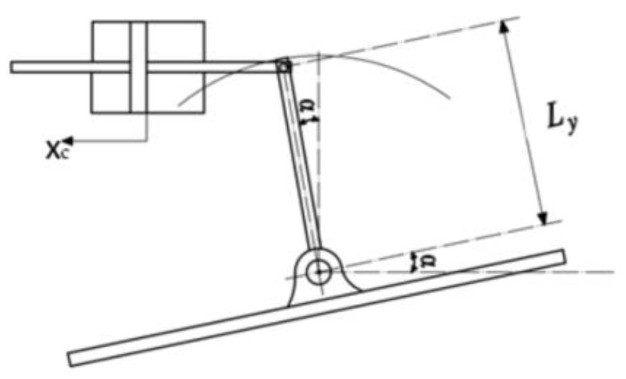
A diagram of the swashplate swing mechanism of the axial variable piston pump is shown in
Figure 3, where
indicates the angle between the swashplate and the zero position, i.e., the inclination angle of the swashplate; and
is the distance between the swashplate swing center and the point of force application of the double rod hydraulic cylinder.
The relationship between the piston displacement and the inclination angle of the swashplate in the variable cylinder can be obtained from the graph as:
which, since the inclination angle of the swashplate is generally small, it is then possible to make because it is considered that the sine (alpha) is approximate to alpha:
From the literature [
28], it is known that the inherent frequency of the oscillation link of the variable cylinder is much larger than that of the proportional directional valve. The influence of the variable cylinder piston mass and viscous damping on its displacement can be ignored, and the variable cylinder is regarded as an integral link. The variable cylinder reset spring only operates the piston back to zero position when there is no pressure, and there is no predefined reset during high pressure operation, so it is not used as the safety device of the variable cylinder; therefore, the influence of the reset spring elasticity on the displacement of the variable cylinder can be ignored. The control volume of the variable cylinder is small and the pilot oil pressure is not high, so the oil volume compression caused by the hydraulic oil pressure change can be ignored.
Based on the above assumptions, the transfer function of the piston displacement of the proportional valve-controlled hydraulic cylinder can be simplified [
29] as:
The variable pump selected in this paper is an axial piston variable pump, the piston axis is parallel to the main axis, and the swashplate has two directions of inclination; ignoring the angular velocity of the swashplate inclination of the variable pump and the influence of the angular acceleration on the control force, the force of the double rod hydraulic cylinder on the swashplate is derived as follows:
Coupling Equations (14) and (15) yields the swashplate displacement transfer function in the variable mechanism:
Since
, Equation (15) can be simplified as:
in the formula:
.
In turn, the displacement of the variable mechanism is obtained as:
The principle of closed-loop adjustment of variable pump displacement is shown in
Figure 4.
is the transfer function from the voltage to the current at the input of the proportional solenoid coil,
is the transfer function from the current in the proportional solenoid coil to the swashplate displacement,
is the transfer function from the hydraulic system operating pressure to the swashplate displacement,
is the voltage at the end of the proportional solenoid–swashplate tilt angle coefficient, and the feedback link is used to limit the swashplate tilt angle at a certain voltage beyond the rated tilt angle at that voltage.
The transfer function from the current in the proportional solenoid’s coil to the displacement of the swashplate is shown in
Figure 4 as:
From the control block diagram, the transfer function
from the end voltage of the proportional solenoid coil to the swashplate displacement can be obtained:
3. Robust Controller Design for Variable Mechanism Control System
There are inconsistencies between the system modeling [
30] and the real model since mistakes are often introduced during procedures like simplification and linearization. Additionally, a variety of disturbances often affect the control field. Therefore, the fundamental goal of robust control is to guarantee that the system performs as intended while accounting for these disturbances and errors, as well as to examine the static and dynamic features and other system performance indicators.
Since
control theory [
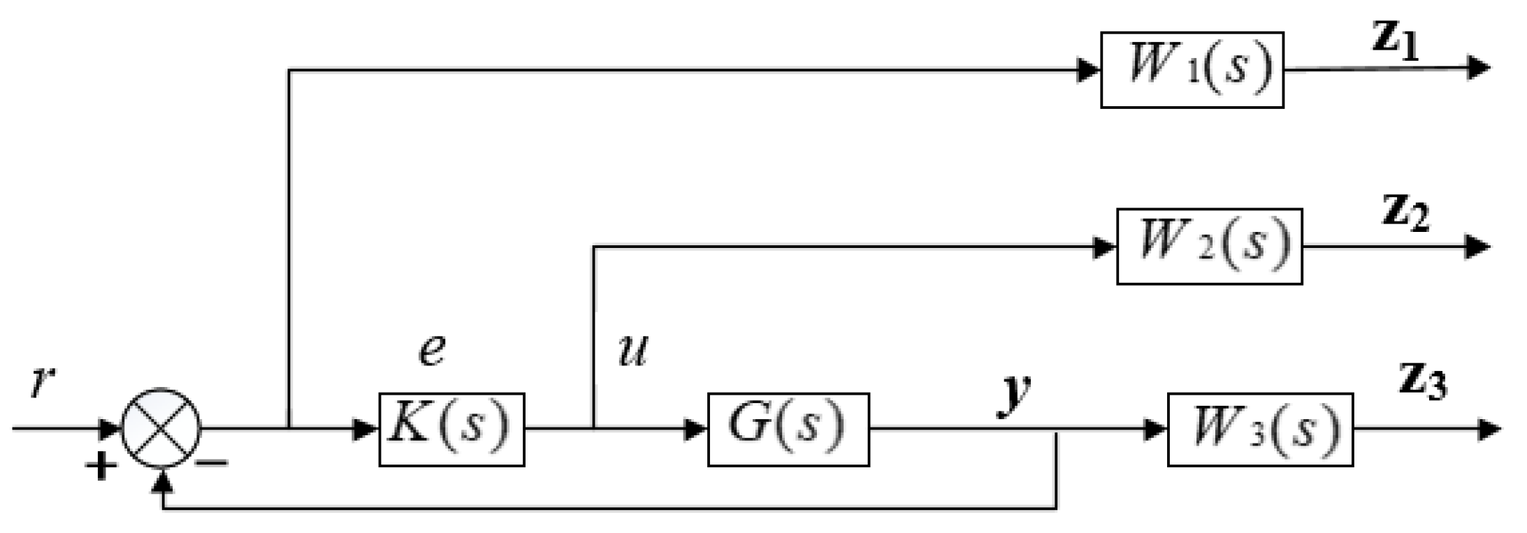
31] has good characteristics, it has been widely studied and the theoretical system is relatively well developed. In this paper, we use the controller to realize the control of the variable mechanism of the axial piston pump;the system block diagram is shown in
Figure 5 under
P(
s) stands for the augmented object model,
K(
s) for the controller model,
z(
t) for the system’s output vector,
w(
t) for its input signal,
u(
t) for its control vector, and
y(
t) for its observation vector.
P(s) can be generally expressed as:
Its corresponding augmented equation of state is described as:
The following is an expression for the transfer function between the input signal
w(
t) and the output signal
z(
t):
When analyzing the robustness of the system with respect to perturbations, we can check whether the value of is less than 1, which indicates that the system is robust and has a strong processing capability for the perturbed signal. control theory uses the “ parameter” to describe the performance index of the system to achieve the purpose of resisting perturbations.
According to previous analysis [
32], the robustness requirement can be achieved by designing the
controller to meet the requirements of certain metrics. In this paper, a hybrid sensitivity approach is used to design the
H∞ controller in order to accomplish loop formation through the design of system performance metrics via the sensitivity functions
W1(
s),
W2(
s), and
W3(
s). To prevent system errors, the correct
W1(
s),
W2(
s), and
W3(
s) must be selected, As shown in
Figure 6.
For this system, the optimization strategy is a weighted hybrid sensitivity, as follows:
To obtain the ideal controller, such that the parameter is minimized:
Step 1. Model the controlled object and analyze the performance requirements of the controlled object to obtain a mathematical description of the controlled problem.
Step 2. The weighting function is selected W1(s), W2(s), and W3(s) to determine the shape of the sensitivity function. W1(s) can generally be made to have a higher low-frequency gain to reduce control errors; W2(s) has a higher high-frequency gain to enhance stability; W3(s) can generally be taken as a smaller constant to increase the response speed and bandwidth of the system.
Step 3. Solve for the system generalized object P(s) and its state space implementation, which in turn leads to the robust controller K(s).
Step 4. Verify that the system performance metrics meet the dynamic and static performance requirements set by the resulting controller. If the requirements are met, the controller can be selected as the final result; if not, it is necessary to go back to Step 1 or Step 2 in a loop.
Combining the program block diagram of the axial piston pump variable mechanism control system with the data in
Table 1, the transfer function of the system can be determined as follows.
Physical measurements of the L4VG125 pump are shown in
Table 1.
Based on the actual situation and the relevant principles described in Step 2, the weighting functions chosen in this paper are in the form of low-pass, proportional, and high-pass, respectively, and are chosen as follows:
After selecting a suitable weighting function, the MATLAB toolbox is used to find the generalized object of the hybrid sensitivity system and the implementation of the state space expression, whose equation can be written as:
The system’s closed-loop function from disturbance to observed output is as follows:
So, the problem of hybrid sensitivity is essentially to obtain a regular rational controller by a reasonable choice of weighting function, such that the system is closed-loop stable and satisfies the following conditions:
The problem can now be transformed into a standard
F(
s) problem, and the controller
F(
s) can be solved using the MATLAB toolkit.
4. Simulation of Robust Control
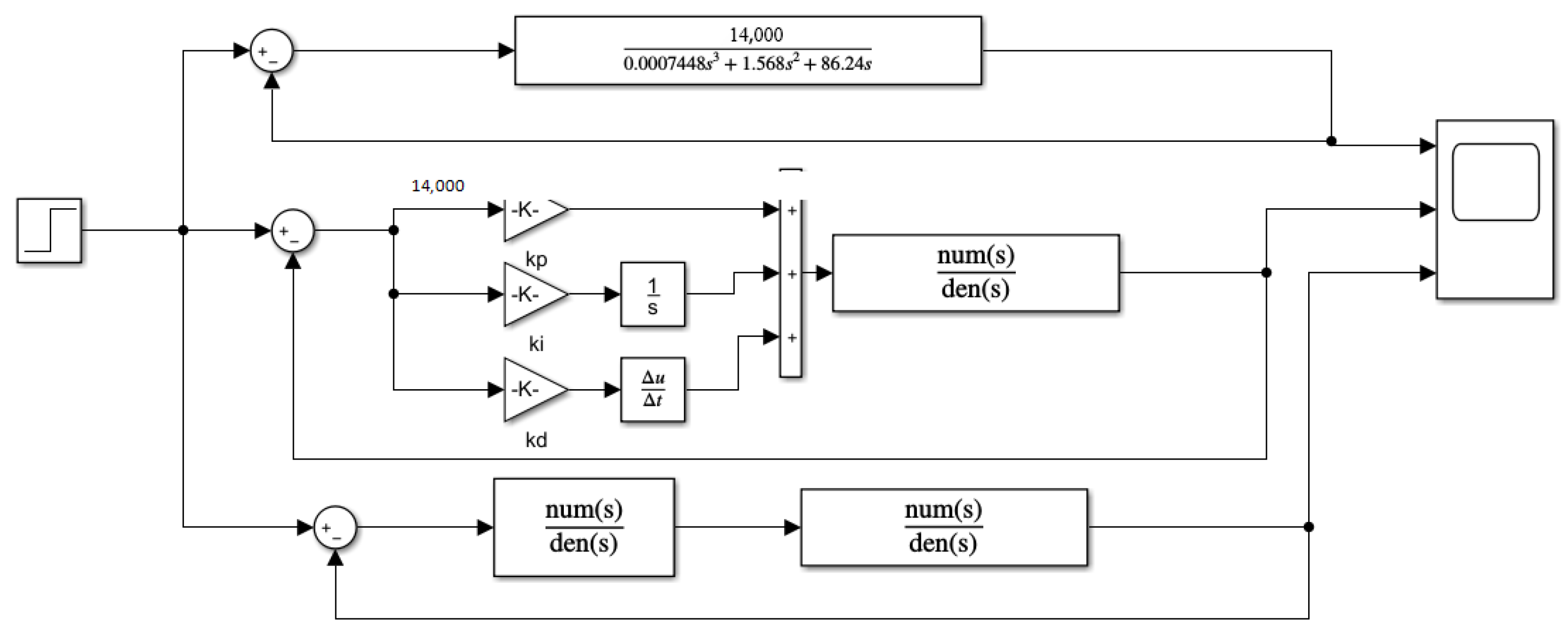
From the above transfer function expressions, the Simulink-related simulation model can be established, and the PID controller is established for comparison.
Figure 7 depicts the simulation schematic, while
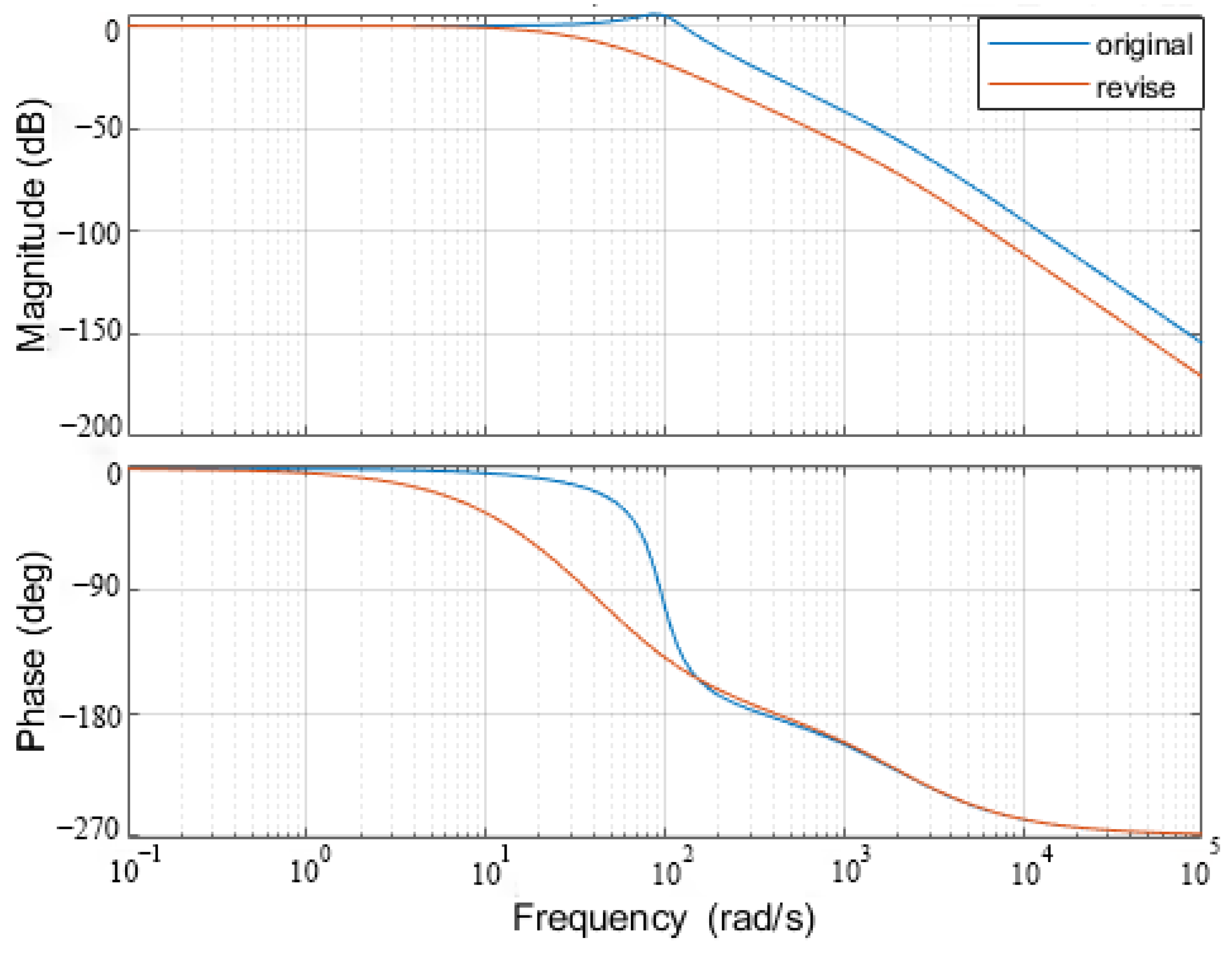
Figure 8 depicts the characteristic amplitude and phase frequency curves of the closed-loop system.
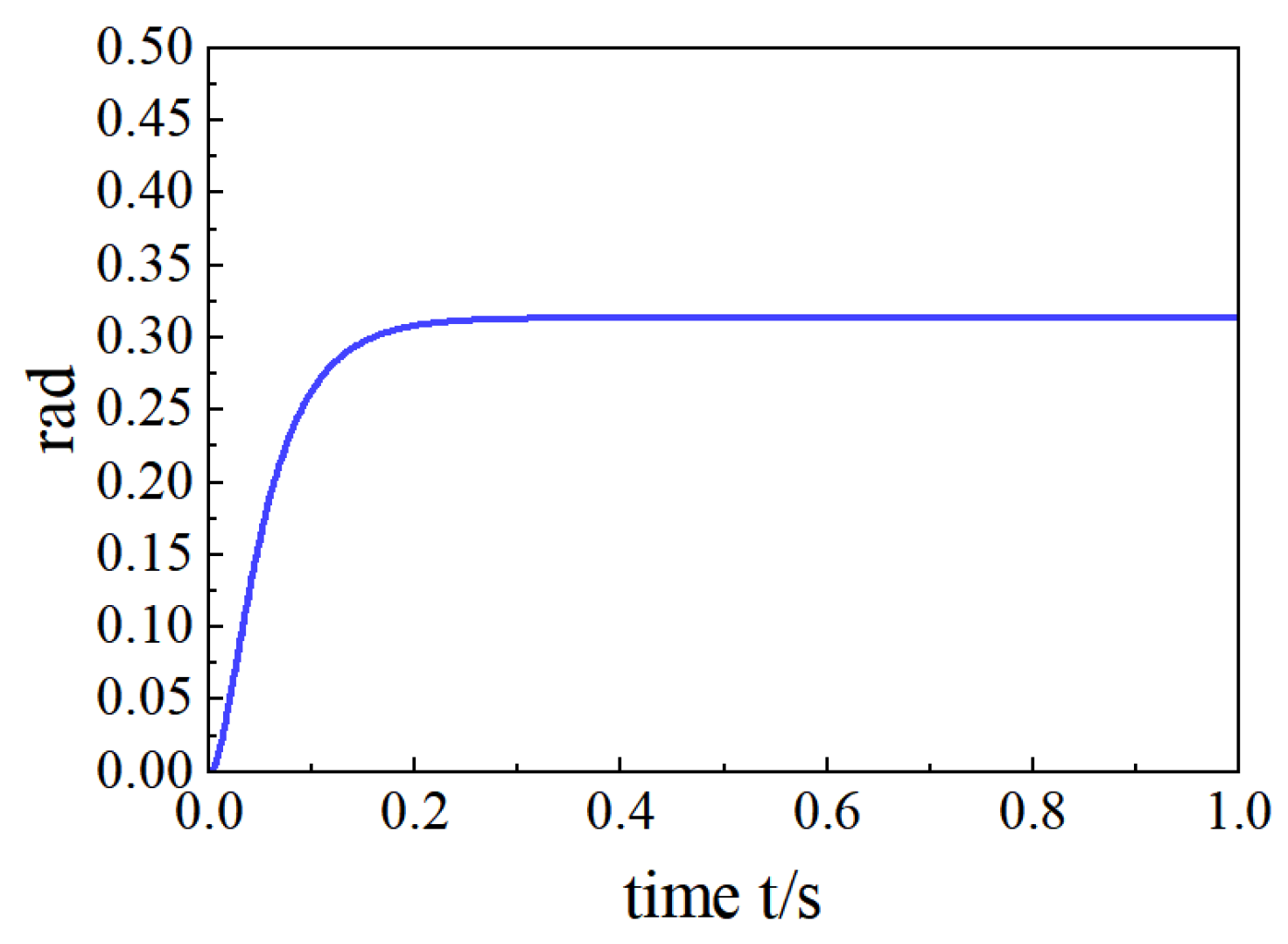
Figure 9 depicts the original image’s response curve,
Figure 10 depicts the response curve under PID control,
Figure 11 depicts the response curve under
H∞ control,
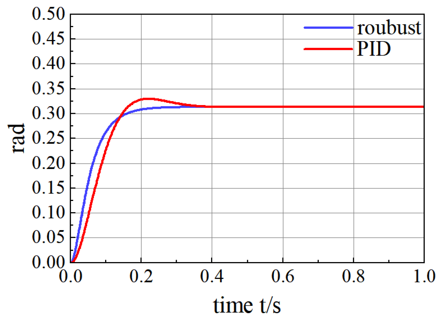
Figure 12 depicts the comparison curve between PID control and
H∞ control, and
Figure 13 depicts the comparison of their square wave responses.
In control systems, “tuning time” is a common performance metric that measures the time it takes for a system to go from an unsteady state to a steady state. In some cases, it can also be thought of as the time it takes for the system response to reach and remain above 90% of the final value.
Among them, the system and the use of hybrid sensitivity controller comparison can be found, with the use of hybrid sensitivity idea design robust controller amplitude margin of 6.73 dB, phase angle margin of 62.8°, and system bandwidth increases when compared to the original system closed-loop amplitude phase frequency characteristic curve..
Simulations show that the H∞ control algorithm, with a rise time of 125 ms and an adjustment time of 211 ms, shortens the adjustment time by 50% compared to traditional PID control, which can result in significant improvements in response speed, control accuracy, and performance.
From the square wave diagrams, it can be concluded that the accuracy of the H∞ controller is higher than that of the transmission PID control.
Summary
The mathematical model of the variable mechanism control system of the axial piston pump is constructed in this article, and the control features of the direct-drive electro-hydraulic servo control system employing PID control and H control are examined. According to the simulation, the rising time of the H control method is 125 ms and the adjustment time is 211 ms. The tuning time "is a key performance indicator that affects the speed and efficiency of the system," and it is decreased by 50% when compared to typical PID control, which dramatically enhances response speed, control accuracy, and performance. As a result, in the electro-hydraulic servo business, H control offers enormous promise.
5. Conclusions
A mathematical model of the variable mechanism of an axial piston pump’s control system is constructed, and the control features of the direct-drive electro-hydraulic servo control system are explored utilizing various control signals as well as PID and H control. The simulation results show that the H control algorithm has a rise time of 125 ms and a tuning time of 211 ms, which reduces the tuning time by 50% and reduces overshooting to 10% when compared to traditional PID control, significantly improving response speed, control accuracy, and performance.
A controller based on the H∞ hybrid sensitivity is proposed after an analysis of the H∞ control method. The findings demonstrate that the traditional PID controller has challenging parameter tuning, significant delays, and significant overshoot between system output and control target, therefore, the contradiction between system stability and fast response is difficult to reconcile. And H∞ control algorithm can successfully solve this contradiction. Therefore, H∞ control has a bright future in the field of electric proportional plunger pump control.


