Article

Analysis of Vibration and Acoustic Radiation Characteristics of Reinforced Laminated Cylindrical Shell Structure

1
School of Mechanical Engineering, Wuhan Polytechnic University, Wuhan 430023, China
2
School of Intelligent Manufacturing, Wuchang Institute of Technology, Wuhan 430065, China
*
Author to whom correspondence should be addressed.
Appl. Sci. 2023, 13(17), 9617; https://doi.org/10.3390/app13179617
Submission received: 6 August 2023 / Revised: 19 August 2023 / Accepted: 23 August 2023 / Published: 25 August 2023

Abstract

:
This paper investigates the acoustic radiation characteristics of reinforced laminated cylindrical shell structures in the medium-low frequency range (1~1000 Hz) of aircrafts, submarines, and deepwater thrusters by combining simulation analysis and experimental testing. The research focuses on reinforced laminated plates, where experimental setup is established to measure structural modal parameters and structural acoustic power, and a finite element model is developed to verify the reliability of the finite element modeling method through comparison with experimental and simulation results. Simultaneously, a finite element model of the reinforced laminated cylindrical shell structure is established, and finite element simulation analysis is conducted to investigate the effects of different reinforcement methods, reinforcement quantities, reinforcement lengths, and reinforcement thicknesses on the acoustic radiation characteristics of the structure. The results indicate that in the frequency range of 1~1000 Hz, ribbed reinforcement exhibits better performance in reducing structural noise radiation compared to longitudinal reinforcement. With the increase in reinforcement quantity and thickness, the structural acoustic radiation decreases. Meanwhile, with the increase in reinforcement length, the overall sound power level of the structure shows a trend of first increasing and then decreasing.

1. Introduction

With the advancement of technology, the impact of noise generated by aerospace equipment, deep-sea apparatus, internal vibrations of launch systems, and friction of surrounding fluid media on the concealment, reliability, and stability of systems has become increasingly critical [1]. In this context, cylindrical shell structures, as commonly employed configurations in aircraft, submarines, deep-water propulsion systems, and other structures, assume particular significance in terms of enhancing their performance. To enhance properties such as strength, rigidity, and stability of cylindrical shells, typical strategies involve the incorporation of hoop ribs or longitudinal reinforcement as primary structural forms. Consequently, research on the acoustic radiation performance of stiffened cylindrical shell structures has garnered significant attention in recent years, emerging as a prominent topic of interest.
Current relevant studies primarily employ theoretical and simulation approaches. Naghsh et al. [2] employed the finite element analysis method to simulate longitudinal stiffeners as discrete beams and compared the vibrational calculation results with those of unreinforced cylindrical shells in existing literature. Based on this comparison, they investigated the influence of shell thickness and longitudinal stiffener parameters on the acoustic radiation characteristics of the reinforced cylindrical shell structure. Maxit et al. [3] propose a semi-analytical method to investigate the acoustic radiation performance of periodically stiffened cylindrical shells. The study takes into account the influence of stiffener section shape and spacing on the radiated noise. Bae and Lee [4] establish an analytical model to investigate the acoustic radiation of submerged, elastically excited stiffened cylindrical shells. The study also takes into consideration the influence of shell impedance on acoustic radiation. Gao et al. [5] employ a hybrid FE-BE method to investigate the acoustic radiation performance of stiffened cylindrical shells under broadband excitation. The study reveals that mechanical forces primarily drive the acoustic radiation at high frequencies. Furthermore, Song et al. [6] propose a hybrid analytical–numerical method for vibro-acoustic coupling, investigating the underwater acoustic radiation characteristics of stiffened cylindrical shells with localized damping. Wang Shiyang [7] examines the relationship between structural vibration and acoustic radiation. Using the example of a cylindrical shell structure with reinforced metal walls, the study conducts simulated analysis of its acoustic radiation characteristics. Zhang Bo et al. [8] utilize a variety of hybrid methods to investigate the acoustic radiation characteristics of stiffened cylindrical shells across the entire frequency range. The study also takes into account multiple factors affecting acoustic radiation. Tong Yunzhe et al. [9,10] investigate the radiation characteristics of longitudinally stiffened infinite cylindrical shells in water using shell theory. Furthermore, building upon this theoretical foundation, the study examines the acoustic radiation of periodically and longitudinally stiffened cylindrical shells under point force excitation. Wang Xianzhong et al. [11] propose a refined transfer matrix method and employ simulated analysis to investigate the influence of boundary conditions and the number of ring stiffeners on the acoustic radiation of stiffened cylindrical shells.
In conclusion, while certain progress has been made in the study of acoustic radiation performance of stiffened cylindrical shell structures, there has been relatively limited exploration by researchers into the integration of experimental and simulation methods to comprehensively investigate the acoustic radiation performance of reinforced sandwich cylindrical shells at mid-to-low frequencies. Therefore, this study adopts a combined approach of experimental testing and simulation analysis to validate the reliability of the finite element modeling method and discuss the influence of reinforcement methods and geometric parameters on the acoustic radiation performance of reinforced laminated cylindrical shells.

2. Experimental Research

2.1. Experimental Setup Construction

The experimental setup is constructed using reinforced laminated plates as the research object. The upper and lower panels of the specimen, as well as the reinforcing ribs, are all made of stainless steel. The rectangular panels have dimensions of 690 × 690 mm and a thickness of 2.55 mm. The upper panel is designed in a “U” shape, bending upwards, with multiple holes on both sides of the “U” shape for easy suspension of the specimen. The reinforcing ribs are bonded to the upper and lower panels using structural adhesive to ensure firm adhesion and prevent specimen disintegration. The reinforcing ribs are “C”-shaped with a thickness of 1.6 mm. The specimen is suspended in the 200 × 200 × 200 mm cubic steel frame using elastic ropes. As shown in Figure 1, the experimental setup for specimen suspension is depicted, and the height of the panel suspension is adjusted to maintain a relatively static state with the steel frame.
After the completion of the experimental setup, pulsed excitation is applied on the plate using an impact hammer, and multiple measurement points are designed and equipped with several vibration sensors on the tested specimen. The sensors are connected to a data acquisition system, which allows synchronous measurement of the excitation and response signals. The acquired data is analyzed using transfer function analysis on a computer to extract and analyze the required measurement data.

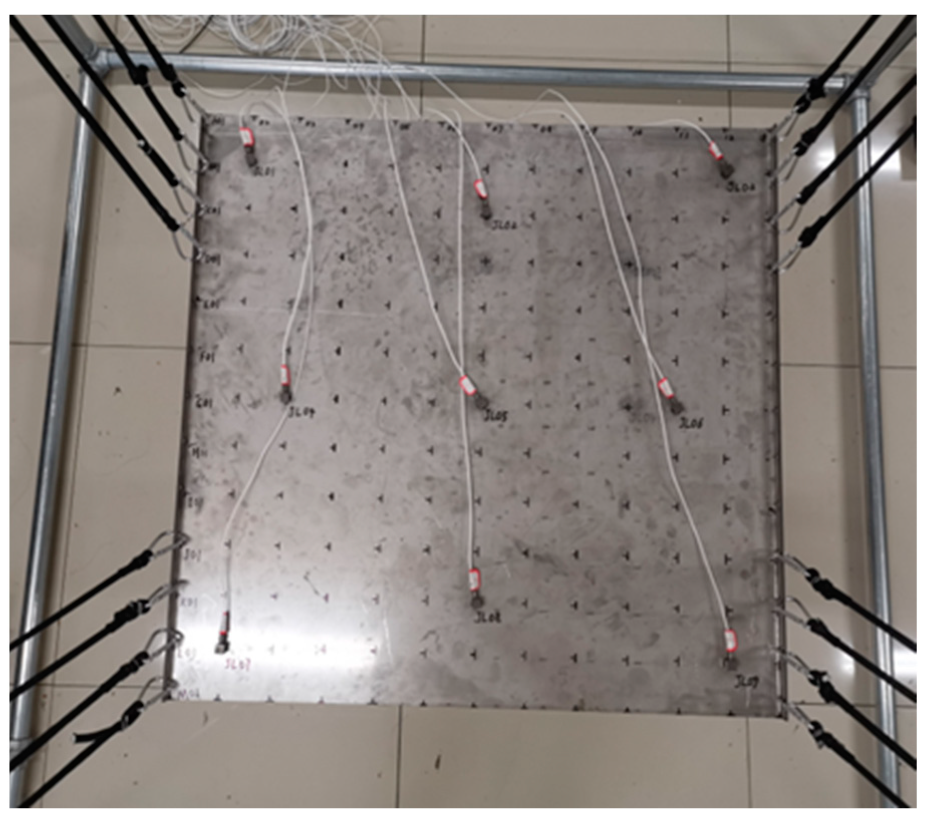
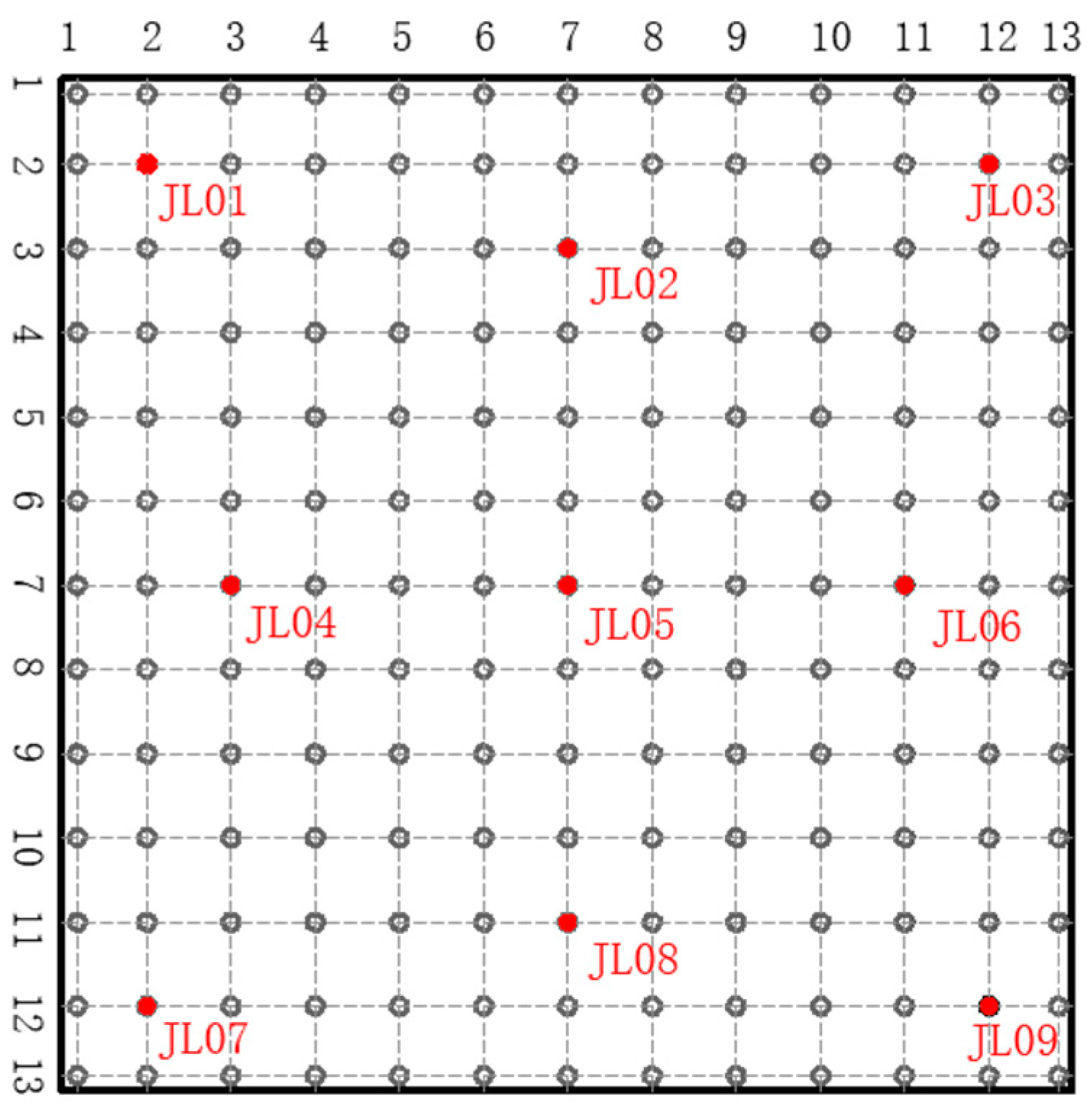
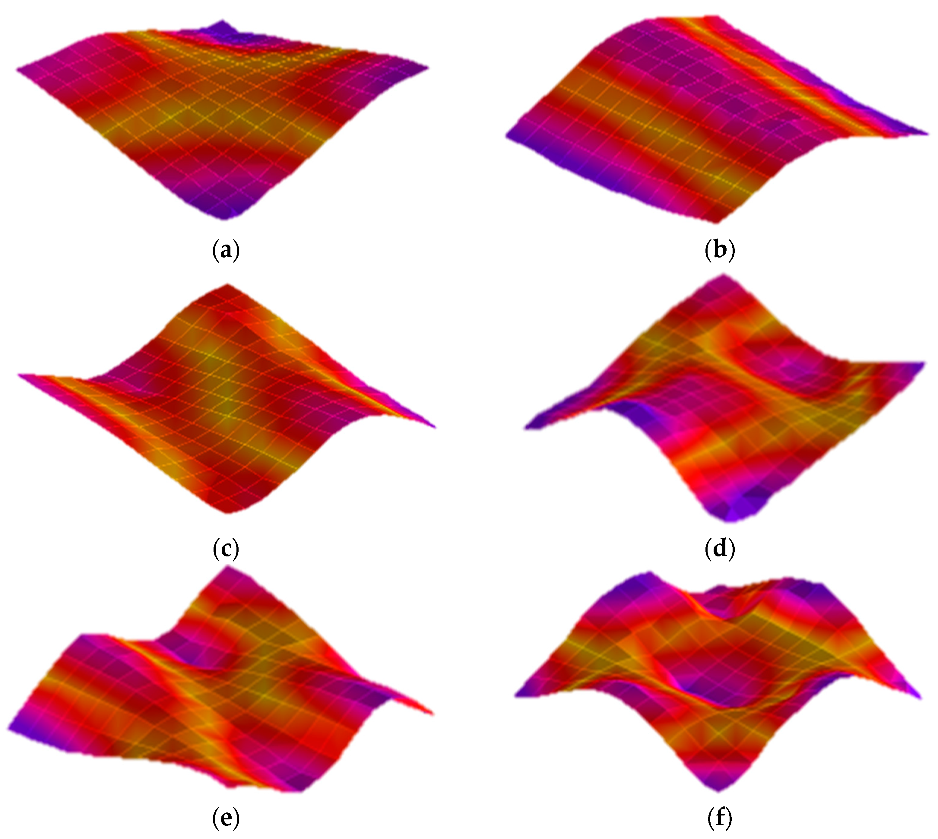
2.2. Modal Experimental Testing

The modal experiment in this paper adopts the form of multiple-point excitation and multiple-point response. The measurement points are uniformly distributed on the panel, with 13 excitation points arranged along the transverse direction and 13 excitation points along the longitudinal direction, all located at the reinforcing ribs. Nine sensors are uniformly attached to the upper surface of the test specimen, and the specific layout of measurement points and sensors is shown in Figure 2. The hammer strikes each measurement point three times, and the data collector performs data acquisition to obtain the modal parameters, including natural frequencies and mode shapes, of the test specimen. The first six structural mode shapes are shown in Figure 3.

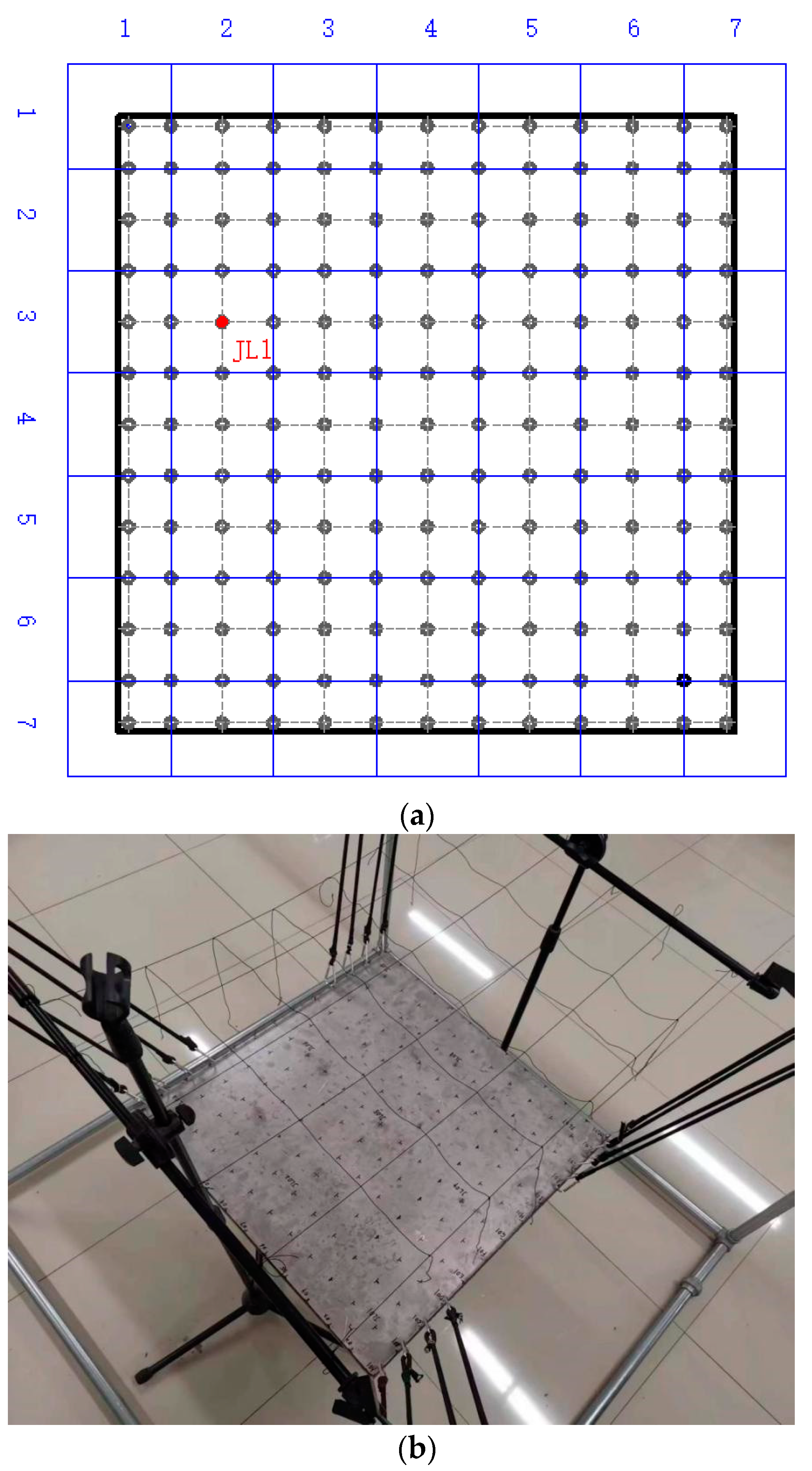
2.3. Acoustic Radiation Experiment

This paper adopts the sound intensity method combined with scanning to measure the radiated noise power of the specimen. By continuously and uniformly moving the sound intensity probe along the planned route on each selected measurement surface, the overall sound power of the desired structure can be quickly and conveniently measured. The continuous tapping method at a single point is employed, and the excitation points are arranged as shown in Figure 4. According to the measurement standard GB/T16404.2-1999 [12], if the shape of the measured sound source surface is flat, the distance between the measurement surface and the sound source surface should be greater than or equal to 200 mm. In this experiment, the excitation surface is located somewhere on the upper panel, so a 7 × 7 measurement surface is arranged 500 mm above the upper panel, as shown in Figure 5.
The impact hammer continuously and uniformly strikes the excitation points arranged. Simultaneously, the sound intensity probe is moved at a constant speed along the planned route from the center of each selected measurement surface. The data collected by the sound intensity probe is inputted into the analysis software through the data acquisition device, and after analysis and processing in the software, the sound power level of the specimen’s radiated noise is obtained.

3. Finite Element Simulation Study

The finite element analysis process is generally divided into finite element preprocessing, numerical solution, and finite element post-processing. In this paper, the initial step involves constructing a three-dimensional geometric model using SolidWorks software. This geometric model is then imported into the HyperMesh meshing software for grid partitioning. Utilizing the OptiStruct simulation module within HyperMesh, the structure undergoes a free modal analysis. The established finite element model is subsequently imported into an acoustic simulation software for finite element acoustic simulation preprocessing, followed by the solution of the required acoustic parameters. Finally, the numerical results are visualized in the form of charts and graphs to facilitate a better understanding of the model’s response.
To validate the accuracy of the finite element analysis method, the reinforced sandwich panel is considered as an example. The finite element model of the reinforced sandwich panel is established using the aforementioned finite element analysis process, and its validity is confirmed through acoustic experimental testing of the reinforced sandwich panel structure. This process also lays the foundation for subsequent acoustic research.

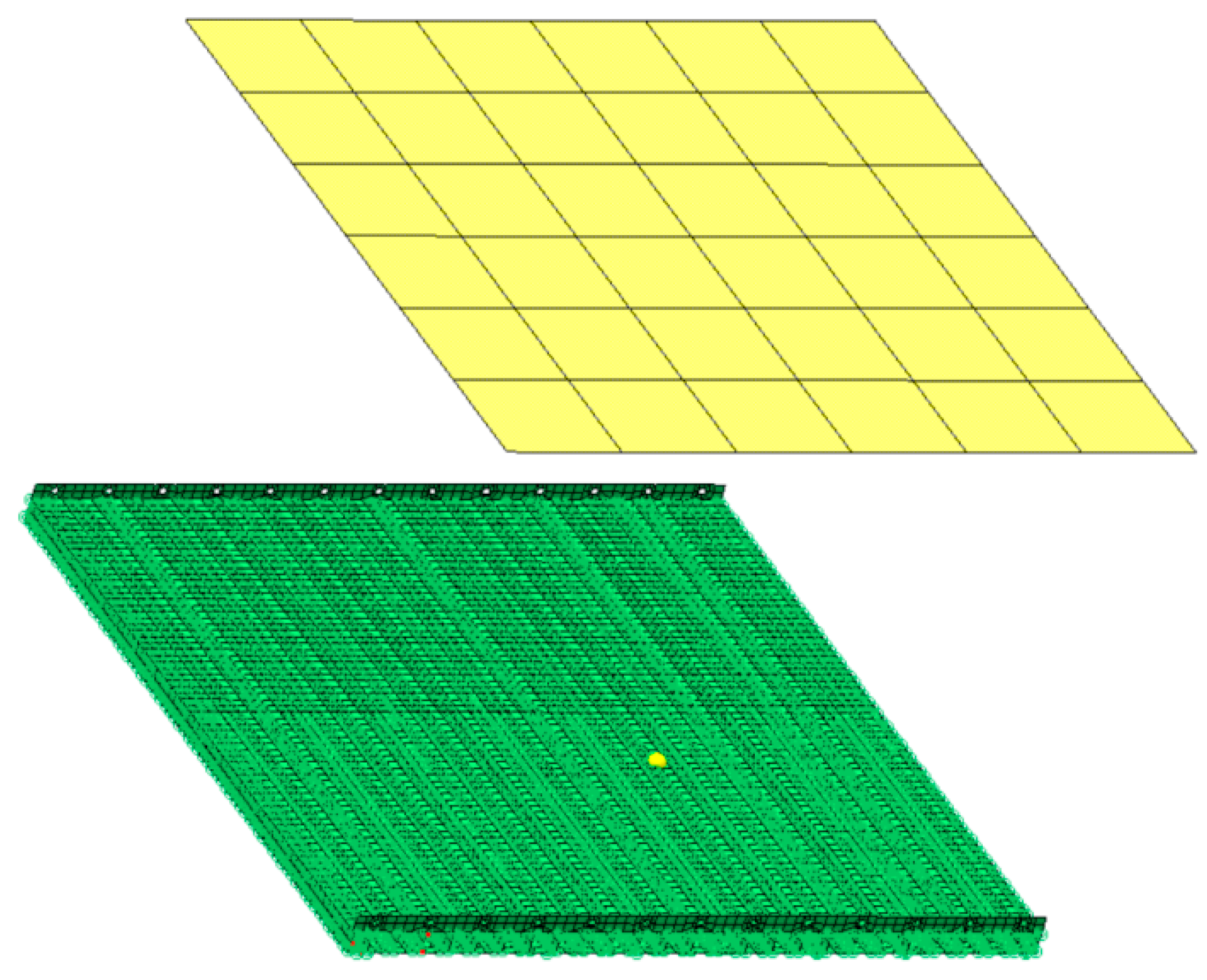
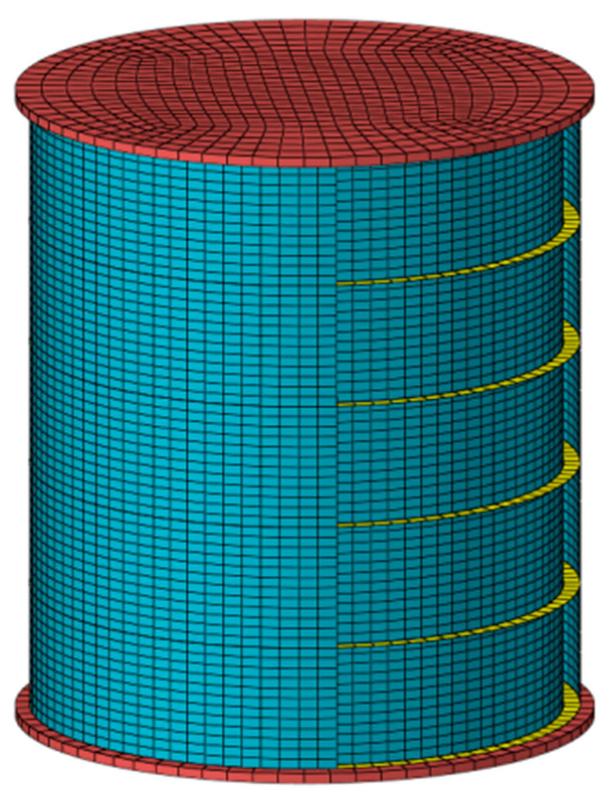
3.1. Finite Element Model

This section focuses on the reinforced sandwich panel as the research subject, with the overall structure composed of upper and lower panels along with reinforcement ribs. The dimensions of the upper and lower panels are 690 × 690 mm, each with a thickness of 2.55 mm. To facilitate subsequent experimental suspension, the upper panel features an extended edge, forming a U-shaped cross-section when viewed head-on. The reinforcement ribs take the form of C-shaped elements with a thickness of 1.6 mm.
The first step involves subdividing the structural grid. Based on the experimental setup constructed as described above, the three-dimensional geometric model is established in SolidWorks software. The three-dimensional model is imported into the HyperMesh finite element meshing software to build the finite element model of the reinforced laminated plate structure shown in Figure 6a,b. In the established finite element model, QUAD quadrilateral elements are used to simulate the upper and lower panels as well as the stiffeners. The mesh size is 10 mm for all elements, totaling 17,489 elements. The connection between the stiffeners and the upper/lower panels is modeled with adhesive bonding, using RBE3 elements for meshing, resulting in a total of 20,249 elements. For the meshing of the fluid cavity, both the exterior and interior cavities of the upper and lower panels are simulated using CHEXA hexahedral elements with a mesh size of 30 mm, amounting to 25,068 elements. The complete finite element model consists of 37,738 structural elements and 25,068 acoustic elements.
The constructed finite element model is imported into the acoustic finite element simulation software. Before acoustic preprocessing of the model, a quality check of all nodal and elemental aspects is conducted. Subsequently, acoustic envelope surfaces are generated, and material properties and fluid attributes for the pertinent structures are established, with detailed parameters presented in Table 1. Meanwhile, the coupling relationship between the structures and the cavity should be established. To simulate the ground effect, the plane of the lower panel’s outer cavity should be defined as a reflective surface. To ensure that sound waves can completely transmit, the outer surfaces of other cavities should be defined as Automatic Matching Layers (AML).
This paper simulates the vibration behavior in a free state without applying any constraints. In the experiment, the load is applied at a certain location on the upper panel, which is consistent with the position of the hammer impact during the experimental test. To better match the actual conditions, the load data during the experiment is imported into the acoustic simulation software, and the load direction is set as vertical, perpendicular to the upper panel. To simulate the actual measurement surface during the experiment, a 6 × 6 plane array is created 500 mm above the upper panel, with seven measurement nodes on each side, as shown in Figure 7, which is the finite element simulation model of the reinforced laminated plate. The Vibro-Acoustic Forced Response module should be accessed, and the direct acoustic-vibration coupling method should be employed. The solution frequency range should be set to 1–1000 Hz with a step size of 1 Hz. After configuration, the acoustic solution should be performed. In the simulation, acoustic power are computed at individual nodes of the planar field points and subsequently are aggregated for overall acoustic power. Finally, a comparison is made between the simulation results and experimental data.

3.2. Finite Element Model Validation

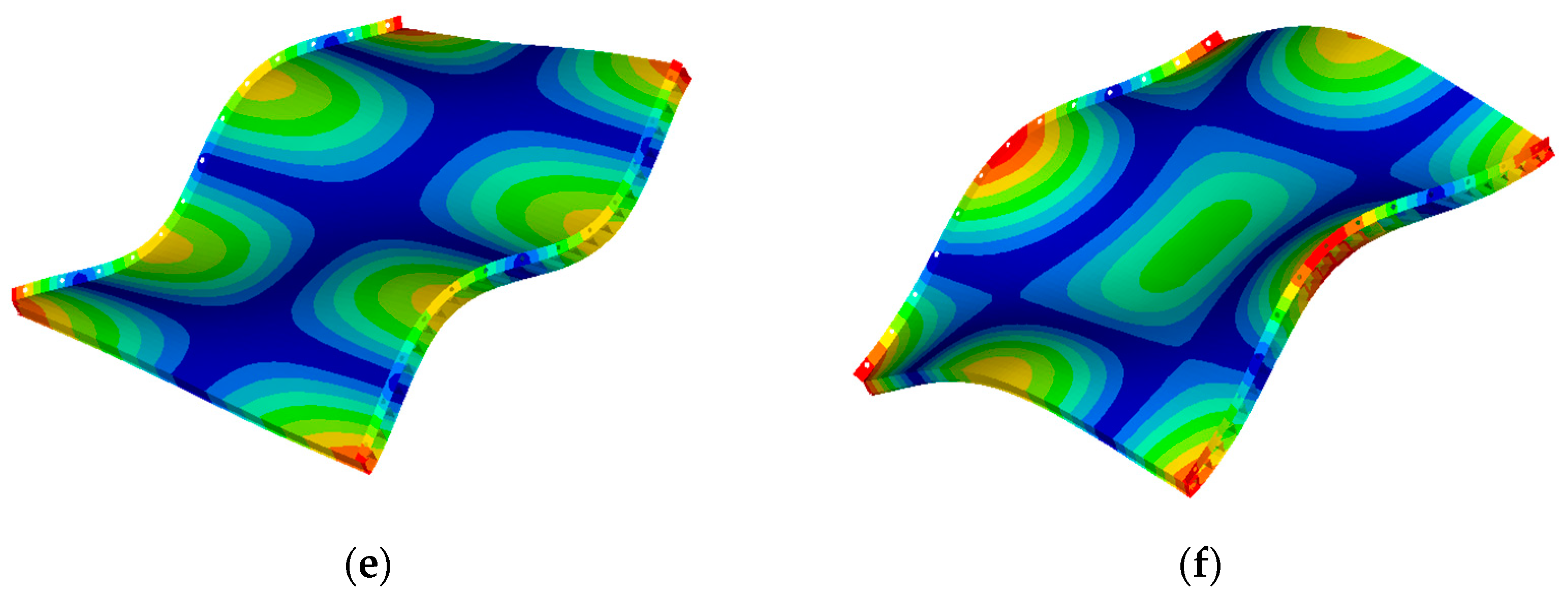
3.2.1. Structural Modes

The model is imported into the OptiStruct simulation solver module of HyperWorks software for free modal analysis. Figure 8 shows the cloud plot of the first six natural modes of the reinforced laminated plate. The simulation results of natural frequencies are compared with the experimental test results, as shown in Table 2. The results indicate a good agreement between simulation and experiment, with errors in the first six natural frequencies, all within 10%. The errors for the 4th and 5th natural frequencies are minimal, being 0.3%, while the error for the 2nd natural frequency is the largest, being 9.1%. Through comparative analysis, the reliability of the finite element model is validated, laying the foundation for subsequent acoustic simulation studies.

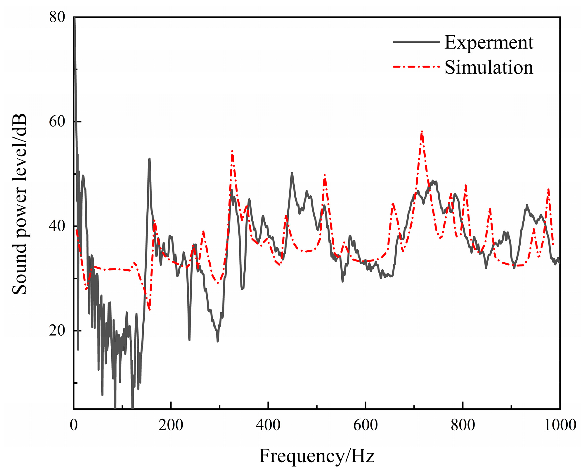
3.2.2. Structural Sound Radiation

In order to verify the accuracy of the finite element analysis method proposed in this paper, a comparative analysis is conducted between the structural sound radiation calculation results obtained from finite element simulation and the experimental measurement data, as shown in Figure 9.
As shown in Figure 9, within the 150–1000 Hz frequency range, two prominent peak frequencies are located at 325 Hz and 738 Hz, with relative deviations of approximately 2.17% and 2.11% from the experimental results, respectively, falling within a reasonable range. Across different frequency ranges, the discrepancies in sound power levels between simulation and experiment manifest as larger simulated peaks and smaller non-peak values. This phenomenon arises from the unevenness introduced by manufacturing processes, which is reflected in the experiments. It leads to structural variations and increased internal damping, simultaneously amplifying vibration energy dissipation and suppressing peaks. Additionally, it results in noticeable vibrations and sound radiation at frequencies beyond the theoretically predicted values. This substantiates the effectiveness of the finite element model and paves the way for subsequent finite element acoustic simulation studies.

4. Analysis of Sound Radiation Characteristics for Reinforced Laminated Cylindrical Shell Structures

4.1. Finite Element Model

Building upon the previously validated method for the finite element model of reinforced laminated plates, this section incorporates the reinforced laminated plate structure as a part of the shell structure and establishes a finite element model for the reinforced laminated composite cylindrical shell.
The finite element model of the reinforced laminated cylindrical shell is shown in Figure 10, and the overall structure consists of a laminated cylindrical shell, reinforcement ribs, and upper and lower cover plates. The total length of the cylindrical shell is 1200 mm, and it is sealed by wooden cover plates with inner and outer shell thicknesses of 2 mm and 3 mm, respectively. The inner shell has a radius of 500 mm, while the outer shell has a radius of 532 mm. The inner and outer shells are connected by reinforcement ribs with a length of 32 mm, thickness of 2 mm, and spacing of 240 mm. The medium between the laminated cylindrical shell layers is air, and there is an air flow field both inside and outside the shell.
The finite element model is imported into the acoustic simulation software for preprocessing. Node quality is checked, and relevant parameters from Table 1 are assigned to the structure and acoustic cavity. The cylindrical shell and reinforcement are constructed from steel material, while the upper and lower cover plates are made of wood with material density of 800 kg/m3, elastic modulus of 2 GPa, and Poisson’s ratio of 0.4. The acoustic medium is air. In typical engineering practice, the imaginary part of the speed of sound is usually no greater than 0.5% of the real part. Therefore, in this study, the real part of the speed of sound is set to 340 m/s, and the imaginary part is set to 0.5 m/s [13].
Two end-restraints are established at the interface between the upper and lower cover plates and the inner and outer shells to constrain the radial displacement between them, and an AML layer is set at the outermost layer of the acoustic envelope. A unit force excitation is applied at the center of the inner shell of the reinforced laminated cylindrical shell, directed radially outward. An ISO standard spherical sound field is established outside the cylindrical shell, and the acoustic computational model is shown in Figure 11. There are a total of 38 computational nodes on the spherical sound field, and the distance of each node from the cylindrical shell is greater than 500 mm. The sound pressure at all nodes on the field is superimposed and averaged to characterize the structural acoustic radiation response. A direct acoustic–structural coupling analysis is conducted, with the solving frequency range set to 1–1000 Hz and solving step size set to 1 Hz. Finally, the solving computations are performed to investigate the impact of cylindrical shell structure’s radiation noise.

4.2. Effect of Reinforcement Method

This section investigates the reinforcement methods for the cylindrical shell, which are divided into circumferential ribs and longitudinal reinforcements. Circumferential ribs are commonly used reinforcement structures in ship hulls, while longitudinal reinforcements are often present in structures like aircraft fuselages to enhance the compressive capability of the structure. Based on the established cylindrical shell model, two types of models are created: one with only circumferential ribs and the other with only longitudinal reinforcements. Both models have 4 and 12 reinforcement bars, and other parameters are consistent with the model established in Section 4.1. By comparing these two types of reinforced cylindrical shell models with the unreinforced laminated cylindrical shell model, the influence of the reinforcement method on the sound radiation performance of the cylindrical shell structure is explored.

4.2.1. Effects of Longitudinal Reinforcement

The sound power level of the cylindrical shell without any reinforcement and with 4 and 12 longitudinal reinforcements is calculated, and the results are shown in Figure 12.
The total radiated sound power levels of 4 and 12 longitudinally reinforced cylindrical shells and the unreinforced cylindrical shell are 83.63 dB, 85.05 dB, and 96.21 dB, respectively. From the perspective of the overall sound power level, the sound radiation performance of the unreinforced cylindrical shell is the best. It can be observed from the graph that, at low frequencies, the addition of longitudinal reinforcement causes an increase in the structural sound radiation peaks. This is because the addition of longitudinal reinforcements increases the circumferential strength of the cylindrical shell, making it difficult for the cylindrical shell to undergo bending deformation, resulting in lower sound radiation power levels compared to the unreinforced cylindrical shell. As the frequency increases, the axial vibration of the cylindrical shell becomes more intense, and at the same time, the restraining effect of longitudinal reinforcement weakens, resulting in more vibration and higher sound radiation peaks. This is unfavorable for reducing the structural sound radiation performance of the cylindrical shell.

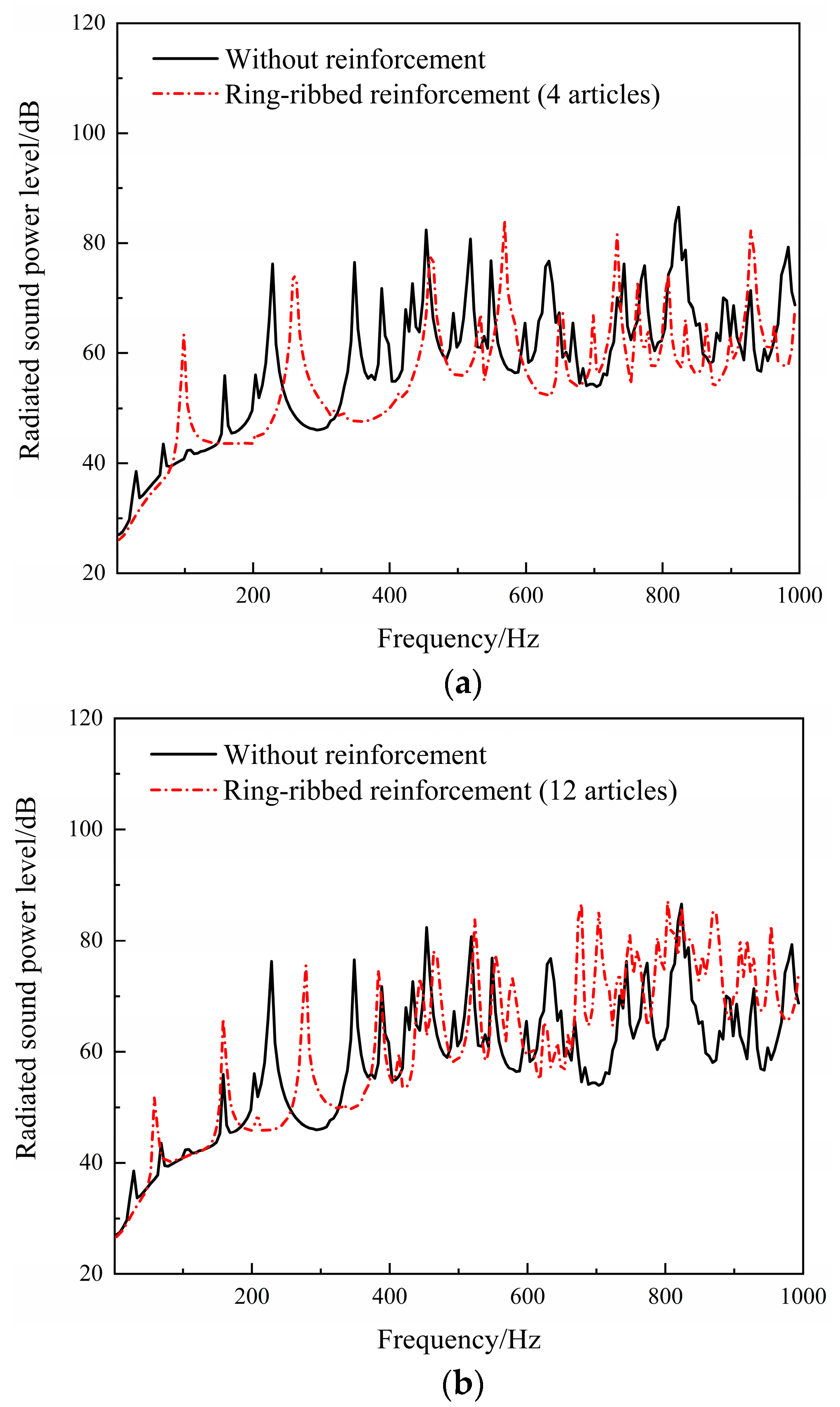
4.2.2. Effects of Ring Stiffening

The radiated sound power levels of the cylindrical shell are calculated for 4 and 12 longitudinal reinforcements and rib configurations, and the results are shown in Figure 13.
The total radiated sound power levels of the cylindrical shell with 4 and 12 circumferential ribs and the unreinforced cylindrical shell are 90.81 dB, 80.02 dB, and 83.63 dB, respectively. From the perspective of the overall sound power level, the sound radiation performance of the cylindrical shell with 12 circumferential ribs is the best. At low frequencies, bending deformation is more likely to occur in the axial direction than in the circumferential direction, and it can be observed from the graph that the addition of circumferential ribs reduces the generation of structural sound radiation peaks. At high frequencies, it can be observed that the radiated sound power level of the cylindrical shell decreases with the increase in the number of circumferential ribs. This is because, in this case, the circumferential ribs effectively strengthen the axial strength of the cylindrical shell, thus suppressing the vibration phenomenon. Therefore, this is beneficial for improving the structural sound radiation performance.

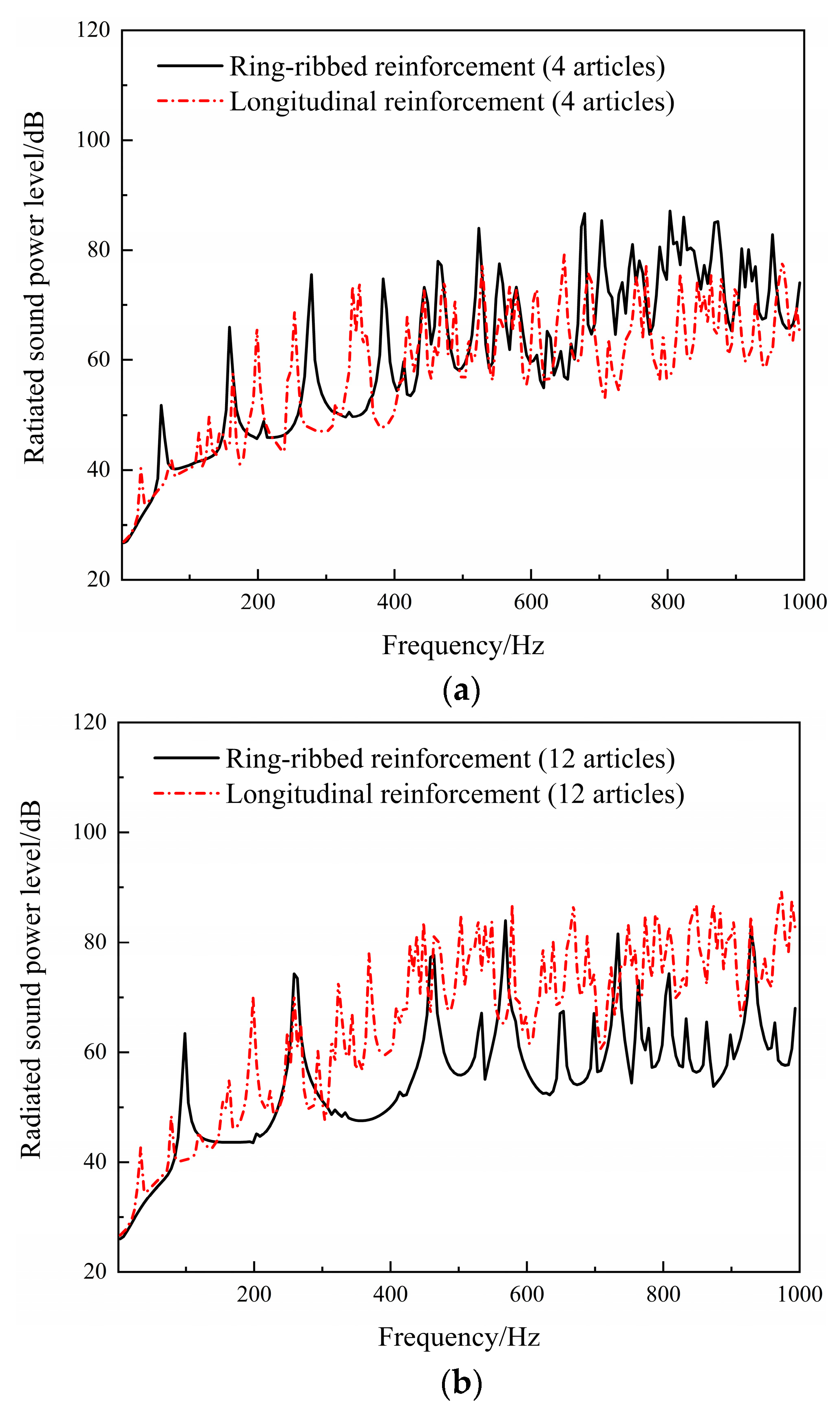
4.2.3. Effects of Different Reinforcement Forms on the Noise Radiation of Laminated Cylindrical Shell Structures

Compare the radiated noise calculation results of the cylindrical shell with circumferential ribs and the cylindrical shell with longitudinal reinforcements with the same number of reinforcements, as shown in Figure 14.
By comparing the radiated sound power level results of cylindrical shells with 4 and 12 reinforcements, it can be observed from the graph that, compared to the case of only circumferential rib reinforcement, the case of only longitudinal reinforcement will result in more radiated sound power peaks. The reason for the generation of more peaks can be analyzed as follows: At low frequencies, without reinforcements, the cylindrical shell is more prone to deform circumferentially, leading to more intense shell vibrations and resulting in more peaks in the radiated sound power. However, circumferential rib reinforcement enhances the axial strength of the cylindrical shell, preventing bending deformation and effectively suppressing shell vibrations, and resulting in fewer sound radiation peaks and a smoother sound radiation power level curve at this frequency range. On the other hand, at high frequencies, the cylindrical shell tends to undergo axial deformation, and longitudinal reinforcement exerts greater constraint on the circumferential direction. Therefore, compared to circumferential rib reinforcement, longitudinal reinforcement intensifies the cylindrical shell’s vibration, leading to increased radiated noise. From the perspective of the overall sound power level, the cylindrical shell with 12 longitudinal reinforcements exhibits a sound power level of 96.21 dB, while the one with circumferential rib reinforcements shows a level of 80.02 dB. The difference between the two is 16.19 dB. Thus, circumferential rib reinforcement proves to be more effective in reducing the structural noise radiation capability. Therefore, subsequent reinforcement configurations will adopt circumferential rib reinforcements for further research and exploration.

4.3. Effects of Reinforcement Quantity

This section explores the influence of the number of reinforcements on the radiated noise of laminated cylindrical shell structures. Based on the finite element model of the cylindrical shell established in the previous section, and with other parameters unchanged, calculations of radiated noise are conducted for laminated cylindrical shell structures with 4, 10, and 16 reinforcements, as shown in Figure 15.
From the graph, it can be observed that at low frequencies, with an increase in the number of reinforcements, the overall sound power level curve shifts towards higher frequencies. Compared to the results with 4 and 10 circumferential rib reinforcements, the sound power level curve of the structure with 16 circumferential rib reinforcements shows fewer peaks in the low-frequency range, which is advantageous for reducing the structurally radiated noise. At high frequencies, a greater number of circumferential rib reinforcements result in stronger axial constraint on the cylindrical shell, leading to a smoother structural sound power level curve and fewer radiated peaks. In the frequency range of 600–1000 Hz, the sound power level curve for the structure with 16 circumferential rib reinforcements is the lowest, indicating the minimum structurally radiated noise. From the perspective of the overall sound power level, the total sound power levels for the structures with 4, 10, and 16 circumferential rib reinforcements are 90.1 dB, 80.82 dB, and 80.28 dB, respectively. It can be observed that with an increasing number of reinforcements, the structurally radiated noise decreases, effectively suppressing the structural sound radiation.

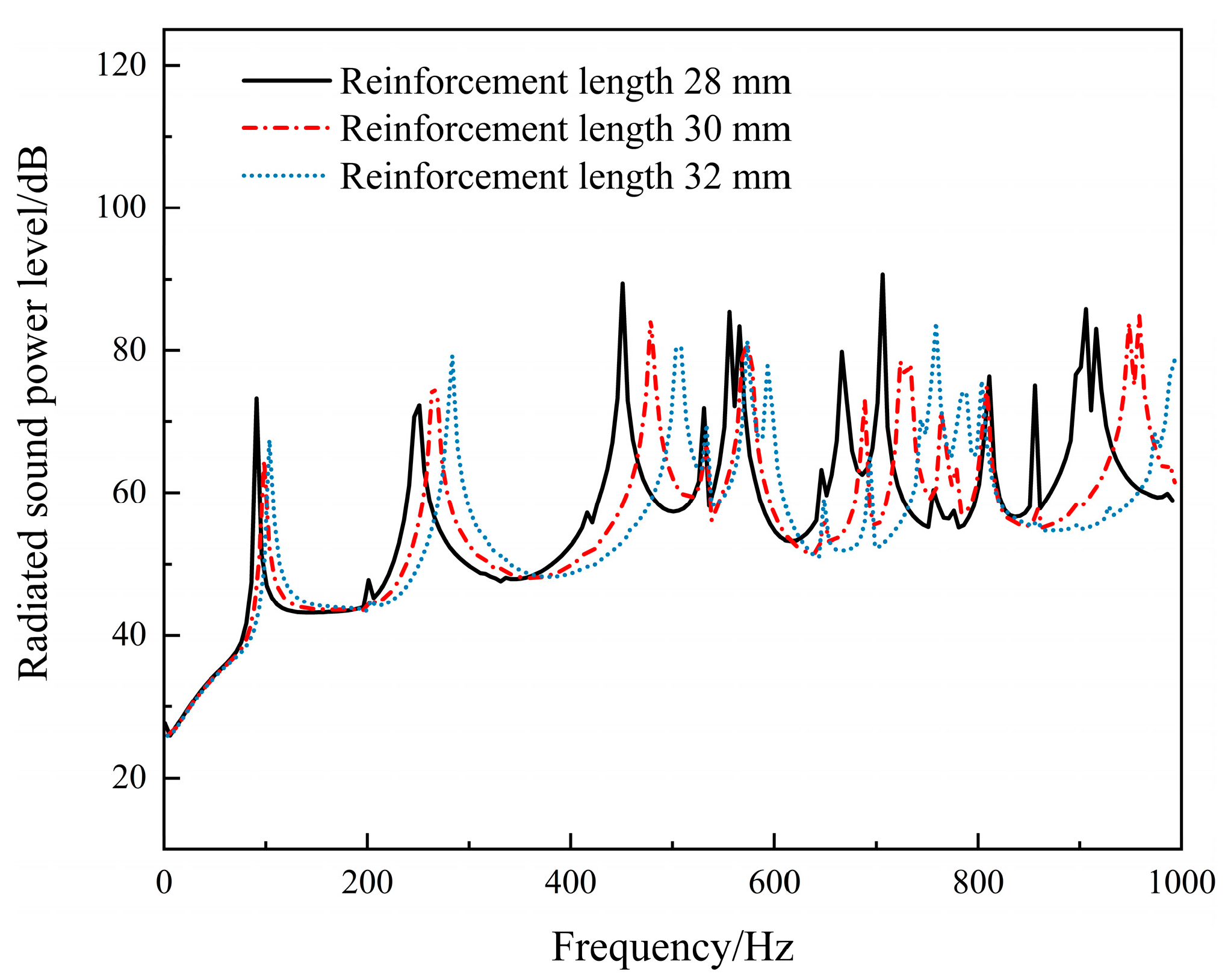
4.4. Effects of Reinforcement Length

This section will explore the influence of reinforcement length on the radiated noise of laminated cylindrical shell structures. Based on the cylindrical shell model with 16 circumferential rib reinforcements, with other parameters unchanged, cylindrical shell structures with reinforcement lengths of 28 mm, 30 mm, and 32 mm are selected for radiated noise calculation, and the results are shown in Figure 16.
From the graph, it can be observed that with the increase in the length of circumferential rib reinforcements, the sound power level curve shifts towards higher frequencies. Compared to the results for reinforcement lengths of 28 mm and 30 mm, the sound power level curve for a reinforcement length of 32 mm shifts towards higher frequencies, resulting in fewer radiated peaks at lower frequencies. From the perspective of the overall sound power level, the total sound power levels for reinforcement lengths of 28 mm, 30 mm, and 32 mm in the reinforced cylindrical shell are 80.14 dB, 79.17 dB, and 80.28 dB, respectively, indicating that the best performance is achieved with a reinforcement length of 30 mm. The results indicate that with the linear increase in the reinforcement length, the sound power level of the cylindrical shell structure does not exhibit a linear change. This may be attributed to the fact that the reinforcing ribs connect the inner and outer shells, playing a role in fixing the inner and outer shells and transmitting vibrations. Therefore, with the increase in the reinforcement length, the stiffness of the cylindrical shell increases, and the cavity between the inner and outer shells also enlarges. At this point, the excitation force is located between the ribs, leading to enhanced shell-to-shell coupling. When the reinforcement length increases to a certain value, shell-to-shell coupling dominates, which in turn enhances the vibration of the cylindrical shell and increases the structural sound radiation. Therefore, the length of the reinforcement should be reasonably selected within the corresponding range of total sound power levels.

4.5. Effects of Reinforcement Thickness

This section explores the influence of reinforcement thickness on the radiated noise of sandwich-reinforced cylindrical shells. Based on the cylindrical shell model with a reinforcement length of 32 mm, and keeping other parameters unchanged, the radiated noise of the cylindrical shell structure is calculated for reinforcement thicknesses of 1.4 mm, 2 mm, and 2.6 mm, and the results are shown in Figure 17.
It can be observed from the graph that in the 1–200 Hz frequency range, the sound power level curves of cylindrical shells with different rib reinforcement thicknesses are almost the same. As the frequency increases, the sound power level peaks shift towards higher frequencies, and the shift is greater for thicker reinforcement. From the overall sound power level perspective, the total sound power levels of the cylindrical shells with reinforcement thicknesses of 1.4 mm, 2.0 mm, and 2.6 mm are 82.4 dB, 80.28 dB, and 78.32 dB, respectively, indicating that the best performance is achieved with a reinforcement thickness of 2.6 mm. The results indicate that as the reinforcement thickness increases, the radiated noise of the cylindrical shell structure decreases. This is because the larger reinforcement thickness increases the contact area between the reinforcement and the inner and outer shells, leading to a more uniform distribution of excitation forces on the shell. As a result, the occurrence of axial bending in the cylindrical shell is less likely, and its vibration is effectively reduced, thus lowering the structure’s radiated noise.

5. Conclusions

This paper adopts a combined approach of experimental testing and simulation analysis to study the sound radiation characteristics of reinforced laminated cylindrical shell structures. The reinforced laminated plate is considered as the research object, and relevant experimental setups are constructed to measure the structural modal properties and sound radiation. At the same time, finite element models are established, and the reliability of the finite element modeling method is verified by comparing experimental and simulation results. Based on this, a finite element model of the reinforced laminated cylindrical shell structure is established, and simulations are performed to discuss the influence of different reinforcement methods, reinforcement quantities, reinforcement lengths, and reinforcement thicknesses on the sound radiation characteristics of the reinforced laminated cylindrical shell structure. The following conclusions are drawn from the study:
  • In the frequency range of 1–1000 Hz, when comparing the cylindrical shells reinforced with ring ribs and longitudinal ribs, both having 12 ribs, the former has a 16.19 dB lower overall sound power level than the latter. This indicates that the ring rib reinforcement performs better in reducing the structural noise radiation.
  • In the frequency range of 1–1000 Hz, when the number of ring ribs is 4, 10, and 16, the overall sound power level of the structure is 90.1 dB, 80.82 dB, and 80.28 dB, respectively. This indicates that as the number of ring ribs increases, the structure’s sound radiation decreases. Additionally, the number of radiation peaks also decreases, and the peak values shift towards higher frequencies. This is due to the increased number of ring ribs, which leads to stronger axial restraint on the cylindrical shell, resulting in a smoother structure sound power level curve and a reduction in radiation peak values.
  • In the frequency range of 1–1000 Hz, the total sound power levels of the rib-reinforced cylindrical shell are 80.14 dB, 79.17 dB, and 80.28 dB, respectively, for rib lengths of 28 mm, 30 mm, and 32 mm. This indicates that with the increase in rib length, the overall sound power level shows a trend of an initial increase and then a decrease.
  • In the frequency range of 1–1000 Hz, the total sound power levels of the rib-reinforced cylindrical shell are 82.4 dB, 80.28 dB, and 78.32 dB, respectively, for rib thicknesses of 1.4 mm, 2.0 mm, and 2.6 mm. This indicates that with the increase in rib thickness, the radiated noise of the cylindrical shell structure decreases. This suggests that increasing the rib thickness increases the contact area between the reinforcing ribs and the inner and outer shells to some extent, resulting in a more uniform distribution of excitation forces on the shell, effectively reducing the radiated noise of the structure.

Author Contributions

B.L. proposed the ideas, steps, and details of the experiment, and most of the experiments were conducted by N.W., Y.T., W.K., L.W. and Z.Z., where N.W. was instrumental in the proper conduct of the experiments and wrote the article together with B.L., and all the authors analyzed the data and discussed the conclusions. All authors have read and agreed to the published version of the manuscript.

Funding

The work is supported by 2022 Knowledge Innovation Dawn Special Plan Project (2022010801020393), Research and Innovation Initiatives of WHPU (2022J04), Natural Science Foundation of Hubei Province (2021CFB292). This work was finished at Wuhan Polytechnic University, Wuhan.

Institutional Review Board Statement

Not applicable for studies not involving humans or animals.

Informed Consent Statement

Not applicable for studies not involving humans or animals.

Data Availability Statement

No new data are created.

Conflicts of Interest

The authors declare no conflict of interest.

References

  1. Xia, Q.Q.; Chen, Z.J. Vibro-acoustic characteristics of ring-stiffened cylindricalshells using structure reactance improvement. J. Huazhong Univ. Sci. Tech. 2012, 40, 90–94. [Google Scholar]
  2. Naghsh, A.; Saadatpour, M.; Azhari, M. Free vibration analysis of stringer stiffened general shells of revolution using a meridional finite strip method. Thin-Walled Struct. 2015, 94, 651–662. [Google Scholar]
  3. Maxit, L.; Guasch, O.; Meyer, V.; Karimi, M. Noise radiated from a periodically stiffened cylindrical shell excited by a turbulent boundary layer. J. Sound Vib. 2020, 466, 115016. [Google Scholar]
  4. Bae, S.; Lee, S. Acoustic Radiation from a Submerged Stiffened Cylindrical Shell Excited by Resiliently Mounted Machinery. Trans. Korean Soc. Noise Vib. Eng. 2015, 25, 33–39. [Google Scholar] [CrossRef]
  5. Gao, C.; Zhang, H.; Li, H.C.; Pang, F.Z.; Wang, H.F. Numerical and experimental investigation of vibro-acoustic characteristics of a submerged stiffened cylindrical shell excited by a mechanical force. Ocean. Eng. 2022, 249, 110913. [Google Scholar]
  6. Zou, M.S.; Tang, H.C.; Liu, S.X. Modeling and calculation of acoustic radiation of underwater stiffened cylindrical shells treated with local damping. Mar. Struct. 2023, 88, 103366. [Google Scholar] [CrossRef]
  7. Wang, S.Y. Theories and Applications of Acoustic Radiation from Reinforced Thin-Wall Structures. Value Eng. 2018, 37, 95–97. [Google Scholar]
  8. Zhang, B.; Xiang, Y.; Li, F.; Guo, N.; Xiao, H.F. Research of Sound Radiation Characteristics of a Stiffened Cylindrical Shell and Its Acoustic Optimal Design. Noise Vib. Control 2017, 37, 31–36. [Google Scholar]
  9. Tong, Y.Z.; Pan, X.F.; Deng, H.C.; Wu, K. Acoustic scattering from an infinitely long cylindrical shell with lengthwise ribs. J. Ship Mech. 2022, 26, 750–760. [Google Scholar]
  10. Tong, Y.Z.; Fan, J.; Wang, B.; Tang, W.L. Acoustic radiation from an infinite cylindrical shell with internal periodic lengthwise ribs. J. Ship Mech. 2021, 25, 246–255. [Google Scholar]
  11. Wang, X.Z.; Jiang, C.M.; Ji, F.; Fang, Y.M. Acoustic radiation of submerged ring-stiffened cylindrical shells with Precise Transfer Matrix Method. J. Ship Mech. 2017, 21, 503–511. [Google Scholar]
  12. GB/T 16404.2-1999; Acoustics—Determination of Sound Power Levels of Noise Sources Using Sound Intensity—Part 2: Measurement by Scanning. State Administration for Market Regulation: Beijing, China, 1999; p. 24.
  13. Du, G.H.; Zhu, Z.M. Fundamentals of Acoustics, 2nd ed.; Nanjing University Press: Nanjing, China, 2001. [Google Scholar]
Figure 1. Experimental setup diagram for the suspended reinforced laminated plate structure.
Applsci 13 09617 g001
Figure 2. Modal experimental test point layout diagram.
Applsci 13 09617 g002
Figure 3. Cloud plot of the first six modal shapes in experimental tests. (a) Cloud plot of the 1st mode shape; (b) cloud plot of the 2nd mode shape; (c) cloud plot of the 3rd mode shape; (d) cloud plot of the 4th mode shape; (e) cloud plot of the 5th mode shape; (f) cloud plot of the 6th mode shape.
Applsci 13 09617 g003
Figure 4. Excitation position for acoustic radiation experiment with a force hammer.
Applsci 13 09617 g004
Figure 5. Arrangement of measurement surfaces for sound radiation experiments. (a) Model diagram of the arrangement of measurement surfaces for sound radiation experiments. (b) Experimental diagram of the arrangement of measurement surfaces for sound radiation experiments.
Applsci 13 09617 g005
Figure 6. Finite element model of the reinforced laminated panel. (a) Schematic diagram of the finite element model structure for the reinforced sandwich panel. (b) Visualization of the finite element model for the reinforced sandwich panel.
Applsci 13 09617 g006
Figure 7. Finite element simulation model of the reinforced laminated plate.
Applsci 13 09617 g007
Figure 8. Cloud plot of the first six natural frequency mode shapes of the reinforced laminated plate. (a) Cloud plot of the 1st mode shape; (b) cloud plot of the 2nd mode shape; (c) cloud plot of the 3rd mode shape; (d) cloud plot of the 4th mode shape; (e) cloud plot of the 5th mode shape; (f) cloud plot of the 6th mode shape.
Applsci 13 09617 g008aApplsci 13 09617 g008b
Figure 9. Comparison between experimental and simulated sound power levels of the reinforced laminated plate.
Applsci 13 09617 g009
Figure 10. Finite element model of a laminated reinforced cylindrical shell.
Applsci 13 09617 g010
Figure 11. Acoustic finite element computational modeling.
Applsci 13 09617 g011
Figure 12. Structural sound power level curves under longitudinal reinforcement. (a) 4 longitudinal reinforcements; (b) 12 longitudinal reinforcements.
Applsci 13 09617 g012
Figure 13. Structural sound power level curve with ring stiffening. (a) 4 circumferential ribs; (b) 12 circumferential ribs.
Applsci 13 09617 g013
Figure 14. Effect of reinforcement on structural sound power level curves at different numbers of reinforcements. (a) Comparison of 4 reinforcements; (b) Comparison of 12 reinforcements.
Applsci 13 09617 g014
Figure 15. Structural sound power level curves under different reinforcement quantities.
Applsci 13 09617 g015
Figure 16. Structural sound power level curves under different reinforcement lengths.
Applsci 13 09617 g016
Figure 17. Structural sound power level curves for different reinforcement thickness.
Applsci 13 09617 g017
Table 1. Relevant structural material parameters.
Density/kg/m3Young’s Modulus/GPaPoisson’s RatioVelocity/m/s
Steel77002100.3/
Structural glue9001.50.41/
Atmosphere1.225//340
Table 2. Comparison of modal experiment and simulation.
Vibration PatternExperimental ValueSimulation ValueInaccuracies
1st(2, 2)126.2 Hz127.1 Hz0.7%
2nd(1, 2)154.0 Hz168.0 Hz9.1%
3rd(2, 3)259.9 Hz250.8 Hz3.5%
4th(3, 2)354.2 Hz355.3 Hz0.3%
5th(2, 4)378.8 Hz379.8 Hz0.3%
6th(3, 3)445.2 Hz442.0 Hz0.7%
7th(2, 5)516.1 Hz522.0 Hz1.1%
8th(3, 4)564.0 Hz567.5 Hz0.6%
Disclaimer/Publisher’s Note: The statements, opinions and data contained in all publications are solely those of the individual author(s) and contributor(s) and not of MDPI and/or the editor(s). MDPI and/or the editor(s) disclaim responsibility for any injury to people or property resulting from any ideas, methods, instructions or products referred to in the content.

