

An Intelligent Approach to the Unit Nesting Problem of Coil Material

Abstract
:1. Introduction
2. Problem Model
2.1. Problem Description
- The parts should be placed within the boundaries of the coil material;
- The part does not overlap with others;
- Each part meets the requirement of the quantity.
2.2. Conceptual Overview
2.2.1. Unit
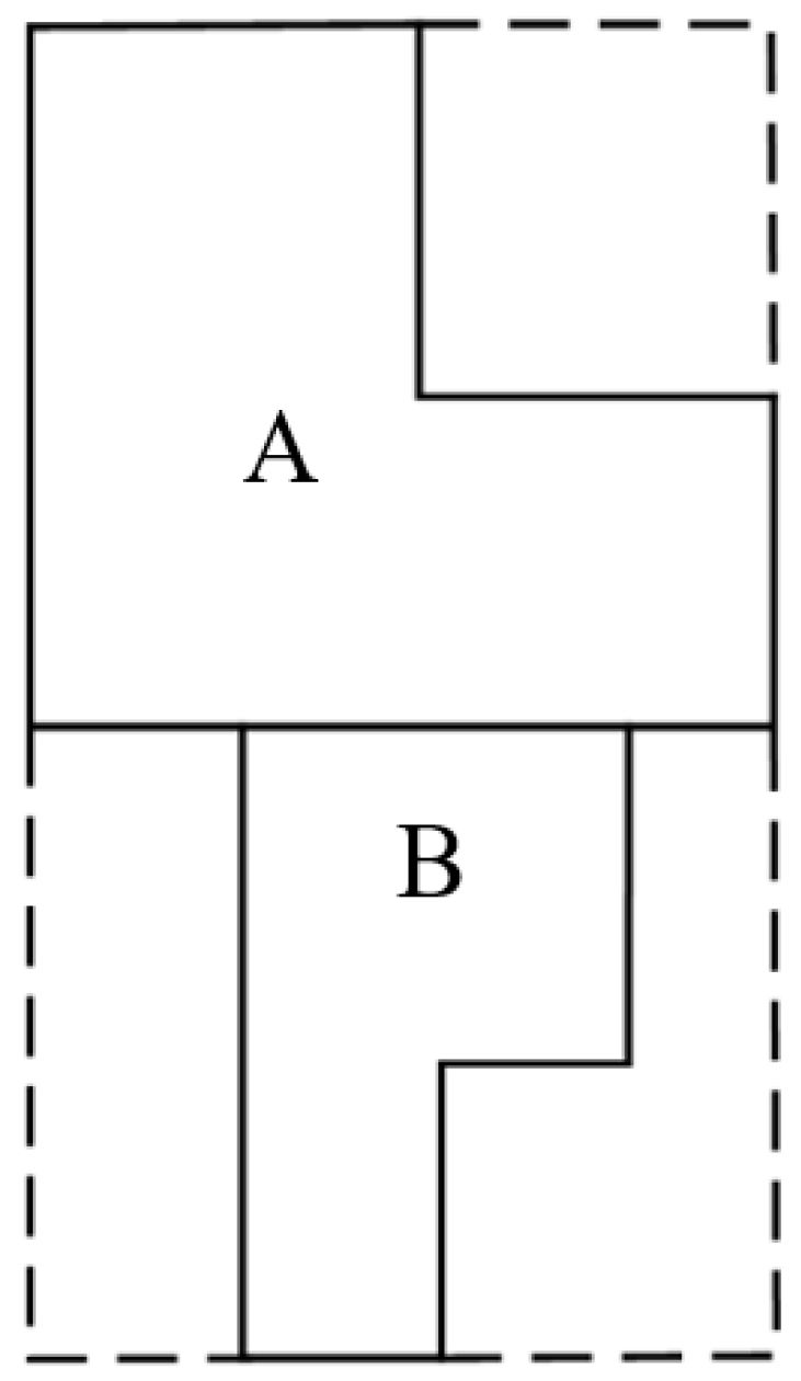
2.2.2. Unit Nesting Approach
2.3. Mathematical Model
3. Solution of the Model
3.1. Positioning Strategy
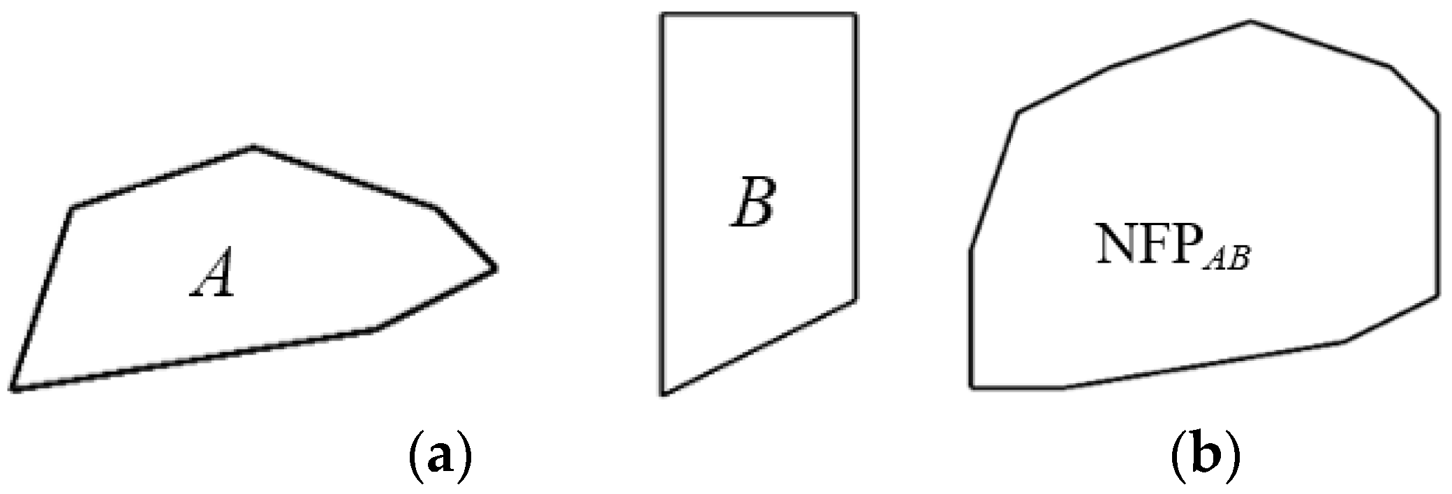
3.1.1. NFP
3.1.2. Greedy Strategy
3.1.3. TOPOS
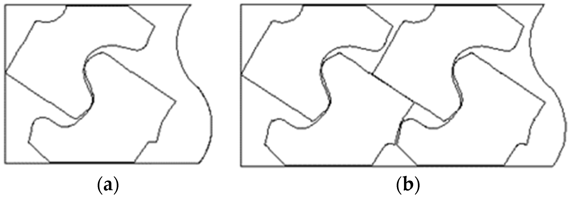
3.1.4. The Optimization of Unit
3.1.5. LH-TOPOS
3.2. Sequencing Strategy
3.2.1. Encoding and Decode
3.2.2. Initial Population
3.2.3. Fitness Function
3.2.4. Selection and Update
| Algorithm 1 Population update |
| 1: while Termination condition not met |
| 2: if |
| 3: Update Prey based on Formula (10) |
| 4: else if |
| 5: Update the first half of Prey based on Formula (11) |
| 6: Update the second half of Prey based on Formula (12) |
| 7: else |
| 8: Update Prey based on Formula (13) |
| 9: end if |
| 10: end while |
3.2.5. Eddy Formation and FAD Effects
3.2.6. Marine Memory
3.2.7. Termination Criterion of Algorithm
3.2.8. Improved Method
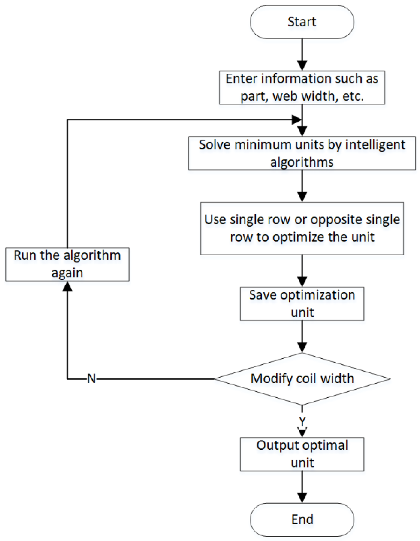
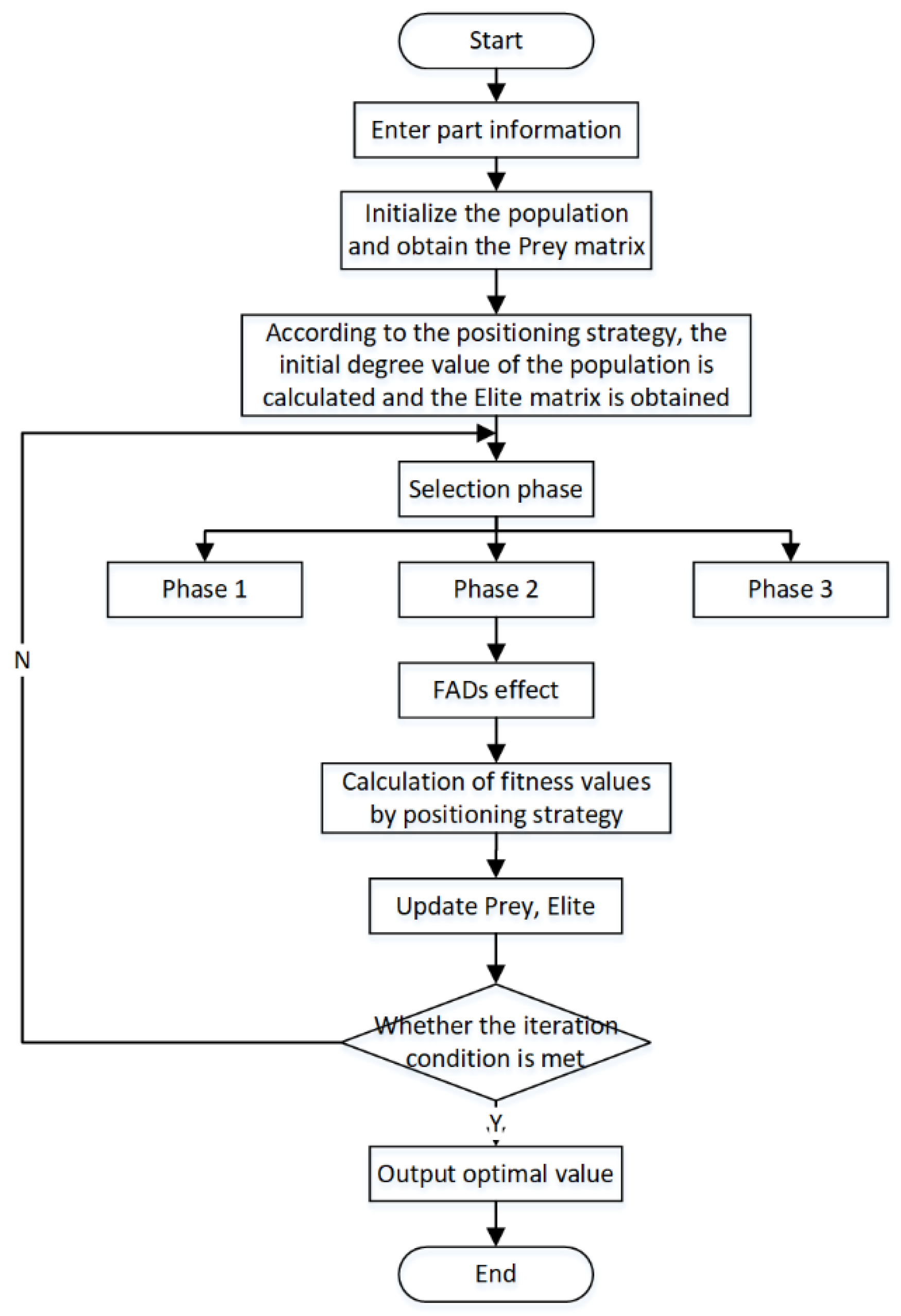
3.3. Algorithm Procedure
- Step 1: Initialize the population;
- Step 2: Calculate the initial fitness values by the LH-TOPOS, and obtain the Prey and Elite;
- Step 3: Update the Prey according to different phases;
- Step 4: Update the Prey and Elite by applying the FAD effect;
- Step 5: Check if the termination condition is satisfied. If yes, output result; otherwise, return to Step 3.
4. Results
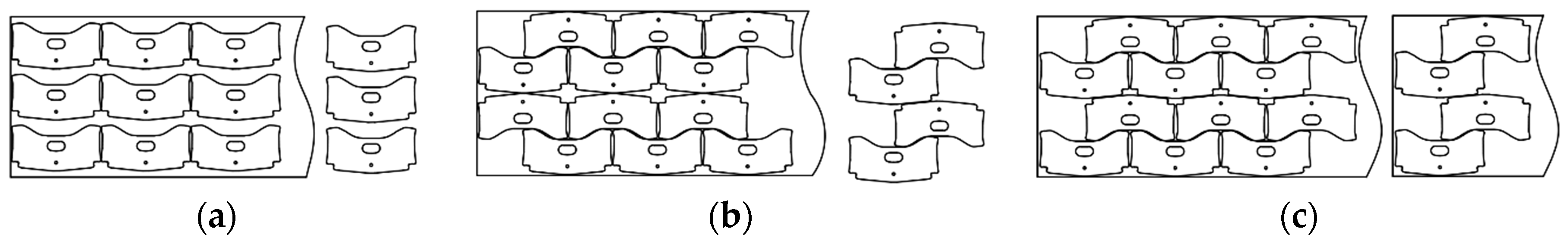
4.1. Case 1
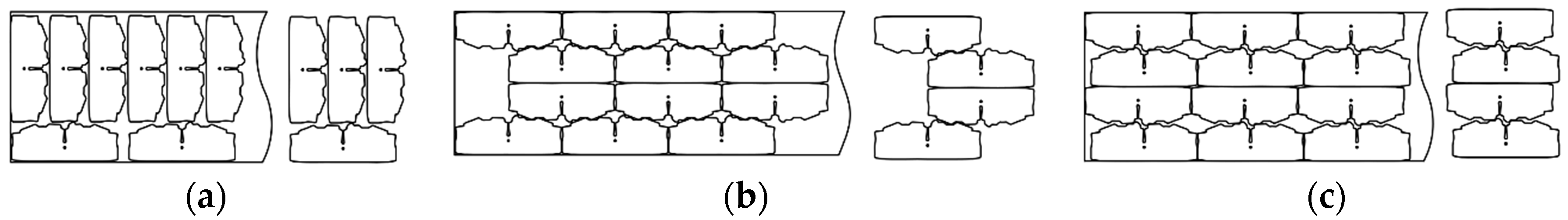
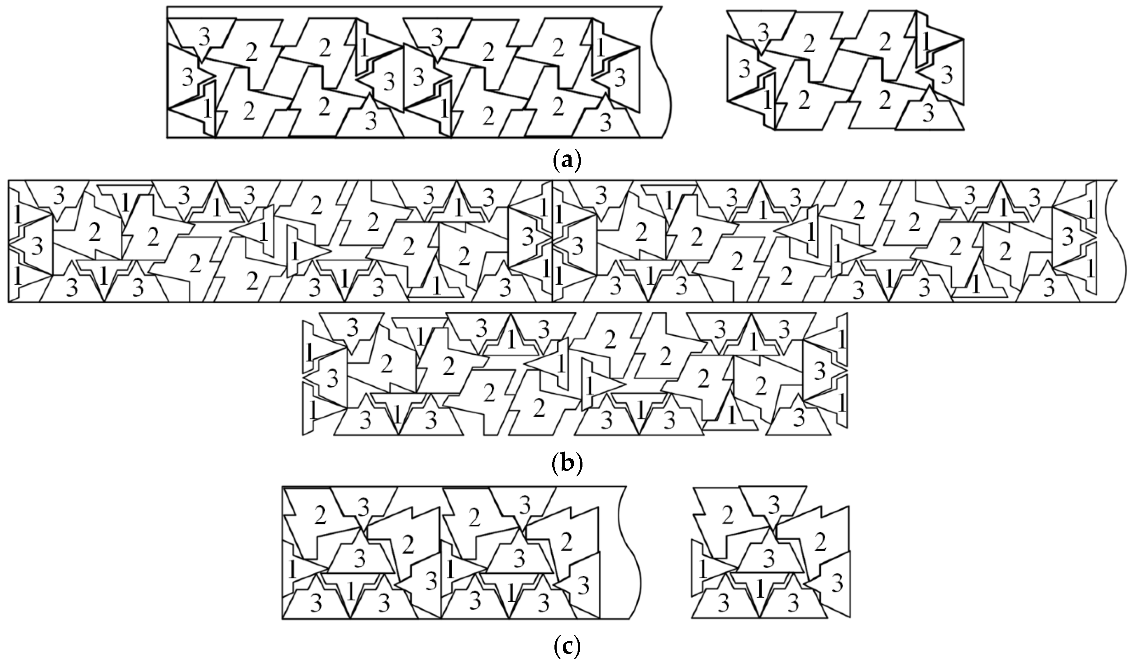
4.2. Case 2
4.3. Results Analysis
5. Discussion
Author Contributions
Funding
Institutional Review Board Statement
Informed Consent Statement
Data Availability Statement
Conflicts of Interest
References
- Feng, Y.X.; Zhong, R.R.; Zhang, Z.F.; Huang, C.; Li, Z.K.; Hu, B.T.; Hong, Z.X.; Tan, J.R. Irregular polyg-ons nesting algorithm driven by design knowledge and application. Comput. Integr. Manuf. Syst. 2023, 29, 593–603. [Google Scholar]
- Gao, B.; Zhang, H.Y.; Zhu, M.H. Optimization algorithm of irregular parts layout for intelligent manufacture-ng. Comput. Integr. Manuf. Syst. 2021, 27, 1673–1680. [Google Scholar]
- Rao, Y.Q.; Peng, D.; Du, B.; Lin, X.H. Research on the Algorithm for Solving the Irregular Parts Packing Problem with bey-ond Boundary Constraint. Comput. Integr. Manuf. Syst. 2023. [Google Scholar]
- Ji, J.; Xing, F.F.; Huang, D.H.; Cui, Y.D.; Shi, N. Optimal two-staged patterns for the two-dimensional cutting problem. Mod. Manuf. Eng. 2021, 81-86+119. [Google Scholar] [CrossRef]
- Wu, D.J.; Yan, C.P.; Li, J.; Cao, W.D. Manufacturability-oriented rectangular parts cutting stock method. Comput. Integr. Manuf. Syst. 2018, 24, 1374–1382. [Google Scholar]
- İsmail, B. Solving 2D strip packing problem using fruit fly optimization algorithm. Procedia Comput. Sci. 2017, 111, 52–57. [Google Scholar]
- Nogueira, D.N.D.; Cristina, A.C.; Fernando, J.O. The two-dimensional cutting stock problem with usable left-overs: Mathematical modelling and heuristic approaches. Oper. Res. 2022, 22, 5363–5403. [Google Scholar]
- Anand, K.V.; Babu, A.R. Heuristic and genetic approach for nesting of two-dimensional rectangular shaped p-arts with common cutting edge concept for laser cutting and profile blanking processes. Comput. Ind. Eng. 2015, 80, 111–124. [Google Scholar] [CrossRef]
- Ranga, P.A.; Julia, A.B.; Antonio, M.S. Jostle heuristics for the 2D-irregular shapes bin packing problems wit-h free rotation. Int. J. Prod. Econ. 2018, 195, 12–26. [Google Scholar]
- Ahmed, M.; Racem, M.; Faouzi, M. An Innovative Genetic Algorithm for a Multi-Objective Optimization of Two-Dimensional Cutting-Stock Problem. Appl. Artif. Intell. 2019, 33, 531–547. [Google Scholar]
- Jiang, C.; Han, X.; Liu, G. Uncertain optimization of composite laminated plates using a nonlinear interval n-umber programming method. Comput. Struct. 2008, 86, 1696–1703. [Google Scholar] [CrossRef]
- Prasad, V.S.S.V.; Hymavathi, M.; Rao, C.S.P.; Bahubalendruni, M.A.R. A novel computative strategic planning projections algorithm (CSPPA) to generate oblique directional interference matrix for different applications in computer-aided design. Comput. Ind. 2022, 141, 103703. [Google Scholar] [CrossRef]
- Diyaley, S.; Chakraborty, S. Metaheuristics-based nesting of parts in sheet metal cutting operation. Oper. Res. Eng. Sci. Theory Appl. 2022, 5, 1–16. [Google Scholar] [CrossRef]
- Qing, G.R.; Qiu, G.W.; Wang, K.; Huang, X. Coil cutting algorithm of single rectangular pieces based on multi-stage layout. Forg. Stamp. Technol. 2022, 47, 73–77. [Google Scholar] [CrossRef]
- Deng, G.B.; Zhu, Q.; Shen, P. Research on coil cutting algorithm based on the two-stage cutting layout. Forg. Stamp. Technol. 2017, 42, 185–189. [Google Scholar] [CrossRef]
- Hung, P.D. A Novel Approach Based on Marine Predators Algorithm for Medical Image Enhancement. Sens. Imaging 2023, 24, 6. [Google Scholar]
- Sumit, K.; Sultan, B.Y.; Pranav, M.; Natee, P.; Sait, S.M.; Seyedali, M.; Riza, A.Y. Chaotic marine predators algorithm for global optimization of real-world engineering problems. Knowl.-Based Syst. 2023, 261, 110192. [Google Scholar]
- Kathryn, A.D.; Subodh, V.; William, B.D. An algorithm for polygon placement using a bottom-left strategy. North-Holl. 2002, 141, 371–381. [Google Scholar]
- Edmund, B.; Robert, H.; Graham, K.; Glenn, W. A New Bottom-Left-Fill Heuristic Algorithm for the Two-D-imensional Irregular Packing Problem. Oper. Res. 2006, 54, 587–601. [Google Scholar]
- Liu, H.Y.; He, Y.J. Algorithm for 2D irregular-shaped nesting problem based on the NFP algorithm and low-est-gravity-center principle. J. Zhejiang Univ. Sci. A 2006, 7, 570–576. [Google Scholar] [CrossRef]
- José, F.; Oliveira, A.; Miguel, G.J.; Soeiro, F. TOPO-A new constructive algorithm for nesting problems. OR Spektrum 2000, 22, 263–284. [Google Scholar]
- Omar, A.; Malek, M.; Mariem, B.A.; Faouzi, M. A New PSO-based Algorithm for Two-Dimensional Non-G-uillotine Non-Oriented Cutting Stock Problem. Appl. Artif. Intell. 2017, 31, 376–393. [Google Scholar]
- Meghdad, H.J.; Reza, T.M.; Ahmad, M.; Abbas, S. Solving an one-dimensional cutting stock problem by sim-ulated annealing and tabu search. J. Ind. Eng. Int. 2012, 8, 1–8. [Google Scholar]
- Jin, P.; Zhang, S.C. A Hybrid Ant Colony Algorithm for the Cutting Stock Problem. In Proceedings of the 2010 International Conference on Future Information Technology and Management Engineering, Changzhou, China, 9–10 October 2010; pp. 47–50. [Google Scholar]
- Chen, T.; Chen, Y.; He, Z.C.; Li, E.; Zhang, C.L.; Huang, Y.Y. A novel marine predators algorithm with adaptive update strategy. J. Supercomput. 2022, 79, 6612–6645. [Google Scholar] [CrossRef]
- Ahmed, M.H.; Mohammed, A.A. Human activity recognition using marine predators algorithm with deep learning. Future Gener. Comput. Syst. 2023, 142, 340–350. [Google Scholar]
- Ma, Y.P.; Chang, C.; Lin, Z.H.; Zhang, X.X.; Song, J.C.; Chen, L. Modified Marine Predators Algorithm hy-bridized with teaching-learning mechanism for solving optimization problems. Math. Biosci. Eng. MBE 2023, 20, 93–127. [Google Scholar] [CrossRef]
- Ma, C.; Zheng, G.H.; Huang, B.; Liu, J. Marine predator algorithm based on Chaotic Opposition Learning and group learning. Comput. Eng. Appl. 2022, 58, 271–283. [Google Scholar]
- Yu, J.Y.; Gao, N.J.; Li, H. Whale optimization algorithm Based on nonlinear cognitive factor and local disturbance. Comput. Eng. Des. 2019, 40, 2861–2866. [Google Scholar] [CrossRef]


| Variable | Variable Definitions |
|---|---|
| W | The width of the coil |
| D | Within the area of coil |
| r | The quantity of part types |
| N | The maximum quantity of parts in a unit |
| Mi | The number of parts i in a unit |
| Within the area of part i | |
| The area of parts i | |
| The angle of parts i | |
| I | The placement order of parts |
| L | The maximum length of a unit |
| The maximum length of two units after combination | |
| sl | The minimum distance of the unit movement without colliding () |
| Part Number | Legend | Size (mm × mm) | Coil Width (mm) |
|---|---|---|---|
| 1 |  | 702 × 357 | 1260 |
| 2 |  | 1973 × 466 | 1850 |
| 3 |  | 897 × 326 | 1260 |
| Part | Punching | Laser Cutting | |||
|---|---|---|---|---|---|
| Manual Layout | Manual Layout | PSO | Unit Nesting Approach | ||
| 1 | Step length (mm) | — | 901 | 901 | 901 |
| Utilization rate (%) | 61.06% | 66.12% | 88.16% | 88.16% | |
| Running time (s) | — | — | 2.37 | 1.98 | |
| 2 | Step length (mm) | — | 318 | 1886 | 1714 |
| Utilization rate (%) | 58.30% | 60.25% | 60.97% | 67.09% | |
| Running time (s) | — | — | 4.71 | 4.55 | |
| 3 | Step length (mm) | — | 775 | 707 | 707 |
| Utilization rate (%) | 75.13% | 81.72% | 90.60% | 90.60% | |
| Running time (s) | — | — | 3.04 | 2.58 | |
| Part Number | Legend | Size (mm × mm) | Coil Width (mm) |
|---|---|---|---|
| 1 |  | 1115 × 878 | 2550 |
| 2 |  | 1448 × 1363 | |
| 3 |  | 1282 × 878 |
| Cutting Method | Layout Algorithm | Step Length (mm) | Utilization Rate (%) | Running Time (s) |
|---|---|---|---|---|
| Punching | Manual layout | — | 63.35% | — |
| Laser cutting | Manual layout | 4371 | 67.87% | — |
| PSO | 10,763 | 75.28% | 14.27 | |
| Unit nesting approach | 2992 | 79.03% | 10.43 |
Disclaimer/Publisher’s Note: The statements, opinions and data contained in all publications are solely those of the individual author(s) and contributor(s) and not of MDPI and/or the editor(s). MDPI and/or the editor(s) disclaim responsibility for any injury to people or property resulting from any ideas, methods, instructions or products referred to in the content. |
© 2023 by the authors. Licensee MDPI, Basel, Switzerland. This article is an open access article distributed under the terms and conditions of the Creative Commons Attribution (CC BY) license (https://creativecommons.org/licenses/by/4.0/).
Share and Cite
Qi, D.; Yang, W.; Ding, L.; Wu, Y.; Tian, C.; Yuan, L.; Wang, Y.; Huang, Z. An Intelligent Approach to the Unit Nesting Problem of Coil Material. Appl. Sci. 2023, 13, 9067. https://doi.org/10.3390/app13169067
Qi D, Yang W, Ding L, Wu Y, Tian C, Yuan L, Wang Y, Huang Z. An Intelligent Approach to the Unit Nesting Problem of Coil Material. Applied Sciences. 2023; 13(16):9067. https://doi.org/10.3390/app13169067
Chicago/Turabian StyleQi, Dezhong, Wenguang Yang, Lu Ding, Yunzhi Wu, Chen Tian, Lifeng Yuan, Yuanfang Wang, and Zhigao Huang. 2023. "An Intelligent Approach to the Unit Nesting Problem of Coil Material" Applied Sciences 13, no. 16: 9067. https://doi.org/10.3390/app13169067
APA StyleQi, D., Yang, W., Ding, L., Wu, Y., Tian, C., Yuan, L., Wang, Y., & Huang, Z. (2023). An Intelligent Approach to the Unit Nesting Problem of Coil Material. Applied Sciences, 13(16), 9067. https://doi.org/10.3390/app13169067