Abstract
In recent years, safety issues involving foundation pits have attracted extensive attention in the industry. The external angle of the foundation pit bears a greater load and is more prone to collapsing. Anchor support technology is one of the most widely used support technologies in construction engineering, but it has the problem of anchor rod crossing and colliding from the initial design stage, and this reduces anchoring force and eventually leads to many safety issues. Compared with traditional methods, Building Information Modeling (BIM) technology can save a lot of time as well as reduce costs, and applying it to concealed engineering can solve the problems that exist during the design stage and reduce unpredictable construction risks. This study proposes an optimization method based on BIM that can accurately and quickly optimize the drilling of anchor rods in the external angles of foundation pits. The results show that the proposed method can reduce the number of anchor rod collision points at the external angle of the foundation pit, minimize the loss of horizontal force caused by anchor rod collision, and ensure the safety and stability of the foundation pit support system.
1. Introduction
In recent years, China’s modernization of engineering construction has achieved great success in the field of infrastructure construction [1,2,3]. Urban architecture has moved from two-dimensional to three-dimensional trends. Many large buildings have supporting basements or underground garages, and the corresponding excavation depths of their foundation pits are very deep. Table 1 shows the number of floors, the total height, and the underground excavation depths of some high-rise and super-high-rise buildings in Beijing. Deep excavation support construction differs from traditional building construction, as its construction conditions are relatively complex. With the continuous increase in excavation depth, when constructing the underground structures of high-rise buildings, the weight of the upper structure becomes substantial, leading to an increased probability of safety hazards and accidents. This necessitates a higher number of requirements for the underground structure’s safety [4,5,6,7,8]. Therefore, the safety issues of foundation pits have received widespread attention in the industry, especially for the outside corner of foundation pits, as it has its own structural problems, bears a larger load, and is, thus, more prone to collapse, which can cause environmental damage in the surrounding area, leading to a series of adverse social consequences. In 1872, the anchor rod slope reinforcement method was first applied to open-pit mining engineering in the UK [9]. In 1958, Bauer in Germany successfully applied anchor rod technology to deep foundation construction [10]. Afterward, anchor rod support technology has been further applied in projects such as foundation pit wall protection, underground buildings, tunnels, and dam reinforcement [11]. Many countries have begun to develop technical specifications for anchor rod support, and this technology has begun to develop rapidly [12]. Now, anchor rod support technology is one of the most widely used support technologies in construction engineering [10,13,14,15]. This technology requires less manpower and material resources, does not require vibration and template operations, and can effectively reduce both working hours and procedures. Applying anchor rods to the surrounding rock of the foundation pit roadway can strengthen it and improve the stability of the foundation pit structure [16,17,18,19]. Taking Beijing as an example, the foundation pit project of the Beijing Trust Building, the Beijing Jingcheng Building, the Beijing Wangfujing Hotel’s underground garage, etc., all use anchor support technology. However, the pile-anchored structure used for supporting the outside corner of the foundation pit currently has the problem of anchor rods crossing and colliding from the initial design stage, making it difficult for the anchor rods to be successfully produced during construction, which, in turn, results in insufficient support depth and anchor rod breakage. In the end, safety issues, such as steel strands entangling on the drill bit and being pulled out, will occur, endangering the safety of workers and also causing a large amount of property damage [20,21]. Therefore, ensuring the safety of the soil at the outside corner of the foundation pit has become increasingly important and urgent.

Table 1.
Situation table of some high-rise and super high-rise buildings in Beijing.
BIM, which stands for Building Information Modeling, is a widely used technology in construction projects [22]. BIM technology utilizes three-dimensional building information models to demonstrate various information about building projects through computer systems. Consequently, these three-dimensional models are applied in the design, construction, and renovation stages of construction projects.
In 2019, Sun Tao summarized five advantages of BIM technology in architectural design: enhanced informatization; targeted modifications to drawings; alignment with industry development trends; facilitation of 3D visualization and integration; and improved architectural design and quality [23].
In 2018, Lin Chunping et al. applied BIM technology to the construction of the Haikou North Tower foundation pit project [24], while in 2021, Jiang Linhai et al. employed BIM technology in a complex foundation pit project located in a busy urban area [25]. Both applications involved detailed design, 4D simulation-based progress tracking during construction, and the use of visualization technology, ultimately resulting in significant time and cost savings in these projects. These applications ensured construction quality and safety, reduced environmental impact, minimized disruption to the lives of nearby residents, and notable economic and social benefits.
BIM technology is now widely utilized in foundation pit projects, providing features such as visualization, simulation, and easy optimization and improvement. Compared with traditional methods, BIM technology can save a lot of time and cost [26,27]. Applying it to concealed engineering can solve the problems that exist during design and reduce unpredictable construction risks [28,29,30,31].
In 2015, Mu et al. summarized the application of BIM technology in deep foundation pit engineering, realizing the collision inspection of the support structure [32]. In 2017, Fu Wenbo used Navisworks collision detection software to conduct collision detection on the anchor rod model in Revit. He verified the accuracy of the software via manual calculations. After that, he adjusted the anchor rod according to the “Building Technical Specification of Protection of Foundation Pit” manually and rechecked the stability of the anchor rod [33]. In 2018, Li et al. used BIM technology to manually adjust the collided anchor rods after completing the collision detection [34]. In 2023, Yin et al. developed a set of Revit external family systems related to foundation pit engineering. He used Revit’s collision check function to conduct collision detection on the model and solved the collision problem by adjusting the tilt angle of the family instance [29].
It can be seen that using BIM technology to solve the problem of anchor rod collision is a common method [35,36,37]. However, manual collision detection and anchor rod adjustment are still challenging due to the following factors:
- When facing a large number of anchor rods, adjustments cannot be made quickly, thereby consuming a lot of time and manpower as well as delaying working hours;
- The accuracy is insufficient, and after adjustment, the angle and hole position may not meet the specifications, or collisions may occur between anchor rods that were originally collision-free;
- The visualization is insufficient, and whether a collision occurs can be observed in the 3D model without intuitive data display.
This paper focuses on the application of BIM technology in anchor rod support, and it proposes a method that can accurately and quickly optimize the drilling angle and the hole position of anchor rods at the external angle of the foundation pit by integrating BIM and visual programming software. This method can theoretically reduce the number of anchor rod collision points at the external angle, making the anchor rods pass smoothly during construction, which would reduce the risk of anchor rod breakage and improve the safety of the foundation pit. The experiment proves the effectiveness and efficiency of this method, which can be a reference point for similar projects in the future.
2. Optimization Process
To create a model of the outside corner support of the foundation pit, BIM was used in accordance with the design drawings. Using visual programming, a program script was developed to check the collision situation of each row of anchor rods in the outside corner support, and the resulting collision data was exported. In the event of a collision, the program script would execute, and the allowable range for the inclination angle would be set based on the national standard “Code for Acceptance of Construction Quality of Building Foundation” (GB 50202-2018), where the maximum allowable adjustment range of the drilling angle is 3°, and the minimum is 0° [38]. The anchor rods would then be classified and analyzed to optimize the drilling inclination angle, and the optimized inclination angle data would be exported. If collision situations persist even after the maximum inclination angle has been optimized, a second program script, also developed using visual programming software, would be executed. In this case, the allowable range for the hole position adjustment would be set based on the national standard “Code for Acceptance of Construction Quality of Building Foundation” (GB 50202-2018), where the maximum allowable adjustment range of the hole position is 100 mm, and the minimum is 0 mm, and the anchor rods would again be classified and analyzed in order to optimize the drilling hole position. The resulting optimized hole position data would then be exported. Figure 1 provides an overview of the process.
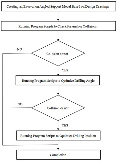
Figure 1.
Optimization Method of Drilling Angle and Hole Position of the Outside Corner Anchor Rods Based on BIM.
3. Overall Process
Through the creation and execution of corresponding script programs in visual programming software, it is possible to detect collisions between anchor rods, optimize the drilling inclination angle, and optimize the hole position between anchor rods. The script program consists of five main modules: data input and extraction; drilling inclination angle optimization; drilling hole position optimization; collision detection; and data output.
3.1. Data Input and Extraction
First, the anchor rod model is selected, and the selected anchor rods are integrated from top to bottom into a list of graphic elements, after which the Excel path is read. The flowchart for this process is shown in Figure 2.
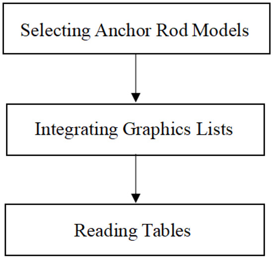
Figure 2.
Flowchart of Data Input and Extraction.
3.2. Collision Detection
To detect collisions between anchor rods, the BIM model is first imported into the visual programming software. Each anchor rod model is then combined, and horizontal collisions between each row of anchor rods are determined. A Boolean value is output, and it is subsequently converted to a collision string. The results of anchor collisions can be viewed in real time in automatic mode. The process is illustrated in Figure 3.
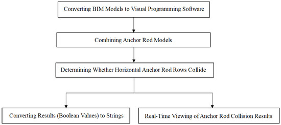
Figure 3.
Flowchart of Collision Detection.
3.3. Optimization of Drilling Inclination Angle
According to the national standard “Code for Acceptance of Construction Quality of Building Foundation” (GB 50202-2018), the maximum and minimum values for the input angle adjustment angle are 3° and 0°, respectively. The allowable range of the inclination angle is defined and imported into an Excel spreadsheet as an integer row number. The initial inclination angle value is then obtained and used in a formula to calculate the new inclination angle offset value, which takes into account the inclination angle adjustment value. Finally, the new inclination angle offset value is assigned to the family instance. The complete process is illustrated in Figure 4.
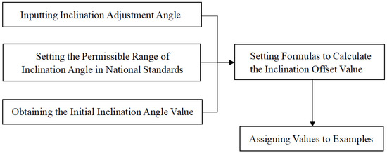
Figure 4.
Flowchart of Drilling Angle Optimization.
3.4. Optimization of Drilling Hole Position
According to the national standard “Code for Acceptance of Construction Quality of Building Foundation” (GB 50202-2018), the input hole position adjustment value has a maximum value of 100 mm and a minimum value of 0 mm. The allowable range for the hole position adjustment is established and defined as an integer row number, which is imported into an Excel spreadsheet. The initial inclination angle value is obtained, and a formula is developed to calculate the new hole position offset value in combination with the hole position adjustment value. Finally, the new hole position offset value is assigned to the family instance. Figure 5 illustrates the entire process.
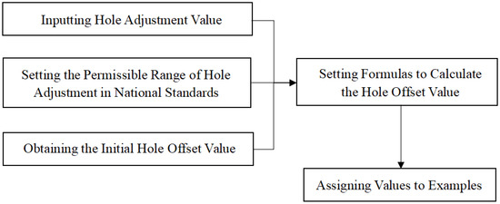
Figure 5.
Flowchart of Drilling Hole Position Optimization.
3.5. Data Output
For the initial model, it is only necessary to read the existing inclination angle of the anchor rod. For adjusted anchor rods, a formula must be set to calculate the optimized range of the inclination angle/hole position adjustment, which is then converted into a string. The data are then sorted in a list, and the rows and columns are swapped and summarized. Finally, the summarized data are imported into Excel, as shown in Figure 6.
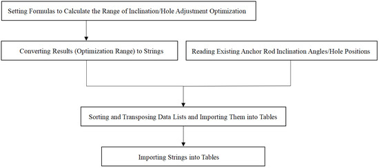
Figure 6.
Flowchart of Data Output.
4. Case Study
4.1. Project Overview
A construction project in Beijing required the excavation of a pit that was divided into eight major layers and their sub-layers based on geological conditions. The excavation was carried out in a uniform and symmetrical manner, layer by layer. Once the pit bottom reached the design elevation, the foundation cushion layer was immediately constructed, and the structure was backfilled in a timely manner after emerging from the ground. Figure 7 is the soil layer diagram that shows the soil layer information.
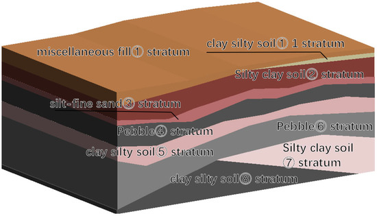
Figure 7.
Soil Layer Diagram.
4.2. Software Selection
While many BIM software applications are available, most have compatibility issues when importing/exporting data between software. As a result, Autodesk’s BIM modeling software, Revit v2019, and its parameterized programming tool, Dynamo, were selected. Dynamo, which is based on Revit, can directly modify the model and has extremely high compatibility with Revit. Revit is currently the most widely used BIM software on the market, and it can satisfy most excavation modeling needs. Even if Revit cannot directly produce a certain type of model, it can quickly create it by nesting parameterized family files. Dynamo can achieve complex functions by combining multiple simple nodes.
4.3. BIM Model
Revit software was used for the three-dimensional design of the excavation support. However, the software cannot directly parameterize the anchor rods. Therefore, nested parameterized anchor rod family files were used to quickly create the anchor rods and produce the model for the outside corner support of the excavation.
4.3.1. Nested Parameterized Anchor Rod Family Files
The nested parameterized anchor rod family files created in Revit software can quickly produce anchor rods of any shape by setting parameters such as “free end length”, “anchor section length”, “extension distance”, “steel strand diameter”, “anchor solid diameter”, “steel strand radius”, and “anchor head to the wall”. Material types of “steel strand material”, “anchor solid material”, and “anchor head material” were also set.
Figure 8 shows the various numerical parameters of the anchor mentioned in the previous paragraph, and Figure 9 shows a completed anchor model.
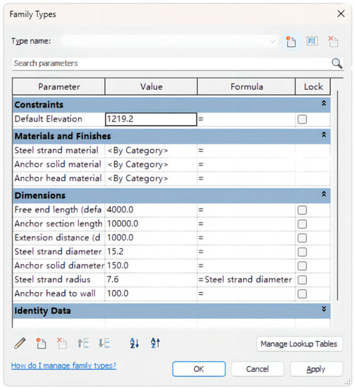
Figure 8.
Parameterized Anchor Model Diagram (Parameter).
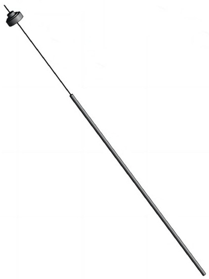
Figure 9.
Parameterized Anchor Model Diagram (Anchor Model).
4.3.2. Production of Outside Corner Support Model for Excavation Pit
The nested anchor rod family file was loaded into the Revit project file, and the outside corner support model for the excavation pit was created using parametric modeling based on the design drawings. The drilling and grouting piles, water stop curtains, crown beams, soil between piles, waist beams, and anchor rods were arranged according to the design information, and the 2D design information was reflected in a 1:1 ratio in the 3D model. Some of the outside corner support models for the excavation pit are shown in Figure 10. The color of the anchors represent the zone in which it is located, that makes anchors easy to find.
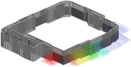
Figure 10.
Outside corner of the Support Model Diagram (partial).
4.4. Program Scripts
Dynamo is a parametric programming tool based on Revit. By writing and running corresponding scripts in Dynamo, five script modules, including data input and extraction, drilling angle optimization, drilling hole optimization, collision detection, and data output, can be completed. According to the process, the five script modules are grouped into three program scripts to optimize the anchor rods. The program scripts run automatically in Dynamo, and they can rapidly complete collision detection and optimization between a large number of anchor rods.
4.4.1. Data Detection
The purpose of the first program script is to perform collision detection on the initial anchor rod model. In this step, three modules, including data input and extraction, collision detection, and data output, are used. The Dynamo program script roadmap for this step is shown in Figure 11.
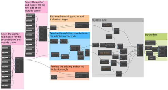
Figure 11.
Script 1: Collision Data Export Dynamo Program Technology Roadmap.
The detection of collisions between selected anchor rods and the selection of the output data table are achieved via the data input and the extraction modules. First, the anchor rod models for the first and second sides of the outside corner are chosen, and the path for optimizing the collision report form is selected. The Select Model Element node is used to choose the anchor rod models and the List.Join node is employed to combine the selected anchor rods into a list of graphical elements from top to bottom. At the same time, the File Path node reads the path of the “Outside Corner Anchor Collision Report Optimization Form”.
The collision detection module examines the collision status between the selected anchor rods. The Revit models are converted into Dynamo software using the Element.Geometry node. Since the anchor rods are created using multiple model-making commands, the Solid.ByUnion node is used to combine each anchor rod model. The Geometry.DoesIntersect node is then utilized to determine whether there is a collision between the anchor rods in the horizontal direction, thereby producing a Boolean value. The If node is used to convert the Boolean value into a collision string.
The data output module exports the collision detection results to a table. The Element.GetParameterValueByName node retrieves the existing anchor rod inclination angle. Using the List Create and List.Transpose nodes, the collision string, the inclination angle, and the headers of various data tables are sorted and transposed, and the imported table data are consolidated. The Data.ExportExcel node imports the summarized data into the “Outside Corner Anchor Collision Report Optimization Form”. The table reflects the collision situation between the anchor rods, providing a visual representation of the collision detection results.
The resulting table after data analysis is shown in Table 2. The two sides of the angle are the straight line where the bolt is located and the straight line intersected by the plane and horizontal plane where the bolt is located, and the angle between the two is the angle of the bolt. “First-side Anchor Rod Inclination Angle of Outside Corner (°)” and “Second-side Anchor Rod Inclination Angle of Outside Corner (°)” are the existing bolt angles. This angle is also the design angle to ensure the full effect of the bolt. “Whether there is a collision between the two Anchor Rods” shows whether two bolts in the same row collide with text results.
Table 2.
“Outside Corner Anchor Collision Report Optimization Form”—Data Inspection.
4.4.2. Borehole Dip Optimization
Script 2 can optimize the borehole dip for anchor bolts that experience collisions. In this step, the four script modules;—data input and extraction, borehole dip optimization, collision detection, and data output—need to be comprehensively used. The Dynamo program roadmap for this step is shown in Figure 12.
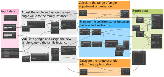
Figure 12.
Script 2: Drilling Angle Optimization and Collision Data Export Dynamo Program Technology Roadmap.
The optimization of the desired anchor rod and the selection of the output data table are accomplished through the data input and the extraction modules. Running program script two in Dynamo’s automatic mode involves selecting the anchor rod models for the first and second sides of the outside corner, choosing the path of the collision report optimization form, inputting the angle adjustment value, and inputting the row number for Excel data entry. The Select Model Element node is used to select the anchor rod models, and the File Path node reads the path of the “Outside Corner Anchor Collision Report Optimization Form”.
The drill inclination angle optimization module receives the angle adjustment value as input. The Number Slider node is used to set the angle value, with a national standard allowing a maximum of 3°, a minimum of 0°, and a slider step size of 1°. The Element.GetParameterValueByName node retrieves the initial inclination angle value. Using a Code Block node, a formula is set up to analyze the anchor rods and the new inclination angle value is calculated based on three values. The Element.SetParameterByName node assigns the new inclination angle value to the family instance.
The collision detection module is used to determine whether collisions occur among the anchor rods. The Revit model is converted to Dynamo software using the Element.Geometry node. Since the anchor rods are generated using multiple modeling commands, the Solid.ByUnion node is used to combine each anchor rod model. The Geometry.DoesIntersect node is employed to assess the occurrence of lateral anchor rod collisions, resulting in a Boolean value. This value is then converted into a collision string using the If node. The Watch node enables real-time visualization of the anchor rod collision results in automatic mode.
The optimized collision detection results are transformed into character blocks and outputted to a table using the data output module. A formula is set using the Code Block node to calculate the range of angle adjustment optimization. A Python Script node is utilized with the following program: OUT = str(“[“+str(int(IN [0]))+”,“+str(int(IN[1]))+”]”) to convert the range into the string format. The summarized data are imported into the “Outside Corner Anchor Collision Report Optimization Form” using the Data.ExportExcel node.
During the optimization process, the accuracy of the angle range allowed by the national standard does not have to be as stated in the text. The accuracy can be adjusted according to the actual needs and the instruments used in order to ensure the accuracy and authenticity of the results. In the collision detection module, the collision results of the anchor bolts can be viewed in real time in Dynamo’s automatic mode, making the optimization process transparent and visible.
4.4.3. Borehole Location Optimization
The process of optimizing borehole locations is similar to that of optimizing borehole dip angles. The core script modules are different, and the four script modules—data input and extraction, borehole location optimization, collision detection, and data output—need to be comprehensively used.
In the execution of program script three under Dynamo’s automatic mode, the first-side anchor rod model, the second-side anchor rod model, the path of the collision report optimization form, the hole adjustment value, and the number of rows for data entry in the Excel table are selected. The Select Model Element node is employed to select the anchor rod models, while the File Path node reads the path of the “Outside Corner Anchor Collision Report Optimization Form”. The Number Slider node is used to set the hole adjustment value, with a national standard allowing a maximum of 100 mm, a minimum of 0 mm, and a slider step size of 1 mm. The integer for the number of rows in the “Outside Corner Anchor Collision Report Optimization Form” is defined.
The Element.GetParameterValueByName node retrieves the initial hole offset value, and the Code Block node is used to set a formula that calculates the new hole offset value based on the angle adjustment value. The Element.SetParameterByName node assigns the new hole offset value to the family instance.
The Revit model is converted to Dynamo software using the Element.Geometry node. Since the anchor rods are generated using multiple modeling commands, the Solid.ByUnion node is used to combine each anchor rod model. The Geometry.DoesIntersect node is employed to assess the occurrence of lateral anchor rod collisions, resulting in a Boolean value. This value is then converted into a collision string using the If node. The Watch node enables real-time visualization of the anchor rod collision results in automatic mode.
The Code Block node sets a formula to calculate the range for angle adjustment optimization. The following program is written using the Python Script node:
if IN[0] == 0:
OUT = str(“”)
elif IN[0] > 0:
OUT = str(“[“+str(int(IN[0]))+”,“+str(100)+”]”)
else:
OUT = str(“[“+str(-100)+”,“+str(int(IN[0]))+”]”)
The program utilizes conditional statements to convert the result into the correct string format for the optimized angle adjustment range. The summarized data are imported into the “Outside Corner Anchor Collision Report Optimization Form” using the Data.ExportExcel node.
As is the case with the borehole dip optimization process, the range allowed for adjusting the borehole location according to the national standard is not limited by the program. It can be adjusted according to actual needs and the instruments used to ensure the accuracy and authenticity of the results. The collision results of anchor bolts can still be viewed in real time in Dynamo’s automatic mode. Figure 13 shows a comparison of anchor bolt collisions before and after optimization. Before optimization, there were collisions between the two side anchors, as shown with the red circles indicating the locations of the collision points. After optimization, all collision points within the red circles disappeared, and there were no longer any collisions present. The optimized results can also be viewed in the table, as shown in Table 3.
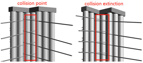
Figure 13.
Schematic Diagram of Anchor Collision Optimization Before and After Comparison.
Table 3.
“Outside Corner Anchor Collision Report Optimization Form”––Drilling Optimization.
The obtained results of the “Specific Range of Allowed Inclination Angle of the Optimized First-Side Anchor Rod of Outside Corner (°)” include specific numerical intervals, such as [17, 18], [18, 18], [26, 28], and textual output denoting “Not calculated”. These numerical intervals demonstrate the adjustable permissible range of drilling angles achieved after optimization. The angles of the first-side anchors are adjusted downward, resulting in larger specific numerical intervals compared to the original angles. The textual output for the fifth-row anchor is due to the absence of collision, rendering optimization unnecessary for the drilling angle. The difference between the maximum value of all specific numerical intervals and the original design values of the “First-Side Anchor Rod Inclination Angle of Outside Corner (°)” column remains at 3°. Furthermore, the optimization of the fifth-row anchor’s inclination indicates a difference of 0° before and after optimization. Both satisfy the standard of “drilling angle ≤ 3°” specified in the “Code for Acceptance of Construction Quality of Building Foundation” (GB 50202-2018).
The results obtained for the “Specific Range of Allowed Inclination Angle of the Optimized Second-Side Anchor Rod of Outside Corner (°)” are similar to those of the “Specific Range of Allowed Inclination Angle of the Optimized First-Side Anchor Rod of Outside Corner (°)”. The difference lies in the upward adjustment of the second-side anchor’s angle, resulting in specific numerical intervals smaller than the original angles. The difference between the minimum value of all specific numerical intervals and the original design values of the “First-Side Anchor Rod Inclination Angle of Outside Corner (°)” column remains 3°, thereby meeting the drilling angle standard of “≤3°” specified in the “Code for Acceptance of Construction Quality of Building Foundation” (GB 50202-2018).
Moreover, the results for the “Specific Range of Allowed Hole Movement of the Optimized First-Side Anchor Rod of Outside Corner (mm)” include specific numerical intervals [35, 100] and textual output denoting “Not Calculated.” These numerical intervals demonstrate the permissible range of downward displacement for the first-side anchor of the third row, with the drill hole position taken as the origin (0-point) for displacement measurement. The reason for obtaining textual output for all anchors except the third row is the absence of collisions after the optimization of drilling angles, rendering any further displacement unnecessary. Additionally, the optimization of drilling angles results in a displacement difference of 0°, indicating no change in hole displacement. The specific numerical values represent the downward displacement of the first-side drill hole after optimization. Specifically, [35, 100] indicate that the first-side anchor of the third row can be displaced downward by a distance ≥35 mm and ≤100 mm. The value ≥ 35 mm ensures that collisions between both side anchors are avoided after optimization, while the value ≤ 100 mm, along with the textual result, conforms to the standard of “drill hole displacement ≤ 100 mm” specified in the “Code for Acceptance of Construction Quality of Building Foundation” (GB 50202-2018).
The physical model intuitively reflects the collision situation, and the table intuitively reflects the optimization results. The entire process is transparent and visible, and the results fully comply with the national standard, accuracy, and authenticity.
5. Conclusions
This study has developed and improved traditional methods for the collision detection of foundation pit anchor rods using BIM technology and optimization technology. A BIM-based optimization method for anchor rod drilling in foundation pits was studied using visual programming software, achieving the following results:
- The program script runs in automatic mode in Dynamo, and digital sliders drive the inclination angle and hole position, updating the model data in real time. This method visually displays the collision situation of anchor rods and makes the optimization process visible;
- The inclination angle optimization program script and hole position optimization program script are based on the anchor rod quality inspection standard in the “Code for Acceptance of Construction Quality of Building Foundation” (GB 50202-2018). The drilling inclination angle and hole position are ≤3° and ≤100 mm, respectively, meeting construction quality acceptance standards. This method ensures the authenticity of the results when compared to traditional methods;
- The input precision during the optimization process is not limited by the script program and can be adjusted according to actual needs and the equipment used, ensuring the accuracy of the results;
- The program script runs in automatic mode in Dynamo, and compared with traditional manual adjustment, it can quickly complete a large number of anchor rod collision detections and drilling optimizations, thereby saving costs;
- By optimizing the inclination angle and hole position of anchor rods at the foundation pit’s outside corner in advance within the design information and national standard error tolerance range, the accurate range value interval can be obtained, effectively reducing the number of anchor rod collision points at the outside corner. After optimization, the collision situation disappears, ensuring the safety and stability of the foundation pit support system.
The results obtained using this method can guide construction, ensuring the safety and stability of the foundation pit support system and providing a reference for solving the problem of anchor rod collision at the outside corner of foundation pits.
Due to the research progress limitations, the drilling optimization script program is divided into the optimization of hole position and inclination angle, and there is still room for improvement with regard to time consumption. Further algorithm optimization is needed to combine the two scripts into one, making the program more intelligent and efficient.
Author Contributions
Conceptualization, Z.J. and X.Z.; methodology, Z.J., D.L. and X.Z.; software, D.L.; validation, D.L., X.Z. and Z.J.; formal analysis, D.L. and X.Z.; investigation, X.Z.; resources, D.L., Z.S. and W.L.; data curation, D.L.; writing—original draft preparation, Z.J., D.L. and X.Z.; writing—review and editing, Z.J., Z.S. and W.L.; visualization, D.L. and Z.J.; supervision, X.Z.; project administration, X.Z., Z.S. and W.L. All authors have read and agreed to the published version of the manuscript.
Funding
This research was funded by Research and practice of multiscale coupling of building information and regional information, grant number 2017-R3-005.
Institutional Review Board Statement
Not applicable.
Informed Consent Statement
Not applicable.
Data Availability Statement
Not applicable.
Acknowledgments
The authors wish to gratefully acknowledge the co-workers at Beijing Huazhu Building Science Research Institute Co., Ltd. for their help during this study. The authors would also like to thank the editors and the anonymous reviewers who presented critical and constructive comments for the improvement of this paper.
Conflicts of Interest
The authors declare no conflict of interest.
References
- Tallest Buildings. Available online: https://www.skyscrapercenter.com/buildings# (accessed on 31 July 2023).
- Countries. Available online: https://www.skyscrapercenter.com/countries (accessed on 31 July 2023).
- High-Quality and Large-Scale Development of Construction Industry, Strengthening Infrastructure, Benefiting People’s Livelihood, and Innovating the Path—Series Report on Achievements in Economic and Social Development Since the 18th National Congress of the Communist Party of China (IV). Available online: https://www.stats.gov.cn/xxgk/jd/sjjd2020/202209/t20220920_1888501.html (accessed on 31 July 2023).
- Chen, Y.B. Analysis of Main Points of Prestressed Floating Anchor Construction Technology. Build. Technol. Dev. 2021, 49, 33–35. [Google Scholar]
- He, L.X. Application of BIM Technology in Foundation Pit Support Design of a Project. Sci. Technol. Innov. 2022, 9, 129–132. [Google Scholar]
- Li, J.J. Analysis of Construction Method of Deep Foundation Pit Support in Construction Engineering. North Archit. 2021, 6, 61–64. [Google Scholar]
- Wei, G.D.; Yang, H.Z.; Wang, X.L.; Liu, Z.Y.; Ren, Y.H.; Yang, H.Z. Application of Deep Foundation Pit Support Construction Technology in Construction Engineering. Value Eng. 2022, 41, 142–144. [Google Scholar]
- Liu, X.; Gu, G.M. Application of BIM Technology to Foundation Pit Support Engineering of Subway Station. Build. Constr. 2018, 40, 1637–1639. [Google Scholar]
- Jia, Z.D.; Jia, L.S.; Huang, S.S. Application and construction management of bolt supporting technology in deep foundation pit engineering. Sichuan Build. Mater. 2023, 49, 85–87. [Google Scholar]
- Li, H.Y. Research of Anchor Supporting Technology in Deep Foundation Pit Engineering. Master’s Thesis, China University of Geosciences, Beijing, China, May 2013. [Google Scholar]
- Bian, P.S. Research on the Deformation Performance of Composite Bracing Technique of Soil Anchors and Soil Nails for Deep Foundation Excavation. Master’s Thesis, Shandong University, Jinan, China, April 2011. [Google Scholar]
- Lu, X.L. Application Research on Anchor Technique in a Deep Foundation Pit Engineering. Master’s Thesis, Xi’an University of Technology, Xi’an, China, June 2018. [Google Scholar]
- Wang, J.; Wei, F.; Ma, S.N. Application of slope support technology in civil engineering. China High New Technol. 2022, 44, 55–57. [Google Scholar]
- Chen, X. Deep Foundation Pit Support Design, Numerical Simulation and Monitoring Analysis—Taking a Project in Beijing as an Example. Master’s Thesis, Hebei University of Engineering, Handan, China, October 2021. [Google Scholar]
- Cai, H. Design of Deep Foundation Pit Support and Numerical Simulation of Excavation in West Square of Xuzhou East Railway Station. Master’s Thesis, China University of Mining and Technology, Beijing, China, December 2021. [Google Scholar]
- Hao, W.H.; Zhang, L. Application of Building Information Model (BIM) Technology in Foundation Pit Support Engineering. Coal Geol. China 2020, 32, 67–70. [Google Scholar]
- Kang, H.P. Sixty years development and prospects of rock bolting technology for underground coal mine roadways in China. J. China Univ. Min. Technol. 2016, 45, 1071–1081. [Google Scholar]
- Yang, J.M. Study on Evolutionary Mechanism of Energy Field and Support Mechanism of Energy-Absorbing Bolt in Deep Roadway. Ph.D. Thesis, University of Science and Technology Beijing, Beijing, China, September 2020. [Google Scholar]
- Wang, M.Y. Hybrid Intelligent System on Coal Roadway Bolting Design. Ph.D. Thesis, China University of Mining and Technology, Beijing, China, June 2016. [Google Scholar]
- Qin, H.Y. Application of BIM Technology Based on CATIA in Tunnel Design. Master’ Thesis, Chang’an University, Xi’an, China, June 2018. [Google Scholar]
- Chen, K.; Liang, Q.M.; Chen, H.B.; Zhu, Q.F.; Gui, F.; Li, P.L. The Process of Anchor Cable Collision of Protruding Corner of Pile-anchor Retaining Structure in Foundation Pit. Constr. Qual. 2014, 32, 9–11. [Google Scholar]
- Gao, Z.L.; Li, H.Y. Application of BIM Technology in the Design of Deep Foundation Pit Support. Intell. Build. Smart City 2021, 9, 70–71. [Google Scholar]
- Sun, T. Consideration on the Advantages of BIM Technology Application to Engineering Design. Intell. Build. Smart City 2019, 61–62+65. [Google Scholar]
- Lin, C.P.; Jiang, Y.J.; Ren, Y.H.; Zhou, Y.Q.; Yang, L. Application of building information modeling in foundation excavation engineering of Haikou North Tower. Constr. Technol. 2018, 47, 1579–1581. [Google Scholar]
- Jiang, L.H.; Liu, S.; Huang, J.J.; Cai, J.Y. Analysis on complex deep foundation pit design based on BIM technology. Yangtze Riv. 2021, 52, 122–127. [Google Scholar]
- Weng, B.Z.; Li, Y.; Wang, W.Y.; Qiao, Q.C.; Peng, M.X. Application of BIM Technology in Supporting Removal Process in Complex Deep Foundation Excavation. Constr. Technol. 2021, 50, 118–121. [Google Scholar]
- Shen, K.; Zeng, T.H. Application of BIM Technology in Construction of Deep Foundation Pit—Taking the Urban Complex Project of Changsha Future City as an Example. Intell. Build. Smart City 2022, 75–77. [Google Scholar]
- Li, P.; Zeng, T.; Reng, P. Application of BIM Technology in Supporting Structure Construction of Deep Underground Foundation Pit. Microcomput. Appl. 2022, 38, 183–186. [Google Scholar]
- Yin, C.Z.; Lu, Y.W.; Wang, L.F.; Xu, Y.B.; Jiang, X.P.; Wang, W.J.; Wang, X.M.; Liu, L.L. Revit-based foreign family construction and BIM model design for foundation pit engineering. Drill. Eng. 2023, 50, 133–141. [Google Scholar]
- Xue, F. The Study of Three-Dimension Visualized Monitoring and Controlling System for the Excavation Bracing System. Ph.D. Thesis, Tongji University, Shanghai, China, November 2006. [Google Scholar]
- Ma, J. BIM Technology for Deep Foundation Pit Support of Metro Station. Master’s Thesis, Shijiazhuang Tiedao University, Shijiazhuang, China, June 2019. [Google Scholar]
- Mu, D.D.; Fu, J.J.; Hu, Z.H.; Shao, L.; Huan, L.P. Application of BIM Technology in the deep excavation Engineering Design. Constr. Technol. 2015, 45, 773–776. [Google Scholar]
- Fu, W.B. Optimum Design and Stability Analysis of Pile-Anchor Retaining Structure in Deep Foundation Pit Based on BIM Technology. Master’s Thesis, Xiangtan University, Xiangtan, Hunan, China, May 2017. [Google Scholar]
- Li, Y.L.; Wang, L.; Wang, Y.N.; Shen, Z.R.; Qu, Y.F. Application of BIM Technology in Foundation Excavation Construction. Constr. Technol. 2018, 47, 898–901. [Google Scholar]
- Chen, X.F. Foundation Pit Supporting Design Based on BIM Technology. Master’s Thesis, Southeast University, Nanjing, China, May 2019. [Google Scholar]
- Liu, P. Study on Optimization of Support Design Scheme of a Deep Foundation Pit in Changchun Research on BIM Technology. Master’s Thesis, Changchun Institute of Technology, Jilin, China, December 2019. [Google Scholar]
- Yu, G.L. Application of BIM Collision Optimization in Pile Anchor Support. Constr. Sci. Technol. 2018, 22, 49–52. [Google Scholar]
- GB 50202-2018; Code for Acceptance of Construction Quality of Building Foundation. China Planning Press: Beijing, China, 2018.
Disclaimer/Publisher’s Note: The statements, opinions and data contained in all publications are solely those of the individual author(s) and contributor(s) and not of MDPI and/or the editor(s). MDPI and/or the editor(s) disclaim responsibility for any injury to people or property resulting from any ideas, methods, instructions or products referred to in the content. |
© 2023 by the authors. Licensee MDPI, Basel, Switzerland. This article is an open access article distributed under the terms and conditions of the Creative Commons Attribution (CC BY) license (https://creativecommons.org/licenses/by/4.0/).