Perspective

Recent Case Histories of Carbon-Neutral Activity Using Ground Improvement Technology in Japan

Kitazume Geotechnics, 2-43-2 Nakashirane, Asahi, Yokohama 241-0004, Japan
Appl. Sci. 2023, 13(15), 8985; https://doi.org/10.3390/app13158985
Submission received: 13 June 2023 / Revised: 19 July 2023 / Accepted: 1 August 2023 / Published: 5 August 2023
(This article belongs to the Special Issue Sustainability in Geotechnics)

Abstract

:
Global warming due to greenhouse gas emissions has led to record-breaking heat waves, torrential rains and droughts on a global scale in recent years. For this reason, people around the world are more keenly aware of the need to reduce greenhouse gas emissions. The construction industry is one of these sources of greenhouse gas emissions. A lot of ground improvement techniques have been developed and applied to improve the physical and mechanical properties of soil in order to achieve stability improvement, ground settlement control, reinforcement, liquefaction prevention, etc. These techniques use a lot of natural materials such as sand and crushed stone and industrial products such as cement. In order to reduce their environmental impact and to economize these techniques, many kinds of industrial waste and by-products have been beneficially used in many types of ground improvement techniques. In response to the growing awareness of carbon neutrality in recent years, it is necessary to further promote initiatives such as the beneficial use of the industrial materials that have been used so far and the development of new materials and construction methods to reduce carbon dioxide emissions. It is expected that various biomass materials will be applied in ground improvement techniques to enhance “negative emission technology”. In this paper, recent developments and applications of certain sorts of environmentally friendly ground improvement techniques, soil densification techniques and soil stabilization techniques are briefly introduced. It is to be expected that these will be further developed and applied to contribute to the reduction in carbon dioxide emissions.

1. Introduction

The Earth’s average surface temperature has shown unusually rapid increases over the past century, primarily due to the greenhouse gases released as people burn fossil fuels. Greenhouse gases, including not only carbon dioxide (CO2) but also methane (CH4), dinitrogen monoxide (N2O) and chlorofluorocarbon (CCl3F) gases, accounted for about 50,000 million tons of CO2 globally in 2018, and 1240 million tons in Japan [1]. This global warming has led to record-breaking heat waves, torrential rains and droughts on a global scale in recent years. For this reason, people around the world are more keenly aware of the need to reduce greenhouse gas emissions.
The construction industry is one of these sources of greenhouse gas emissions, and accounts for about 43% of Japan’s carbon dioxide (CO2) emissions. Since cement, one of the most frequently used materials in construction, is a relatively inexpensive, mass-produced, safe and durable material, it has been used in building and infrastructure for more than 100 years. It is made of limestone, which contains a large amount of carbon dioxide. In the cement manufacturing process, a large amount of carbon dioxide is emitted during the firing of the limestone. More than 30% of Japan’s carbon dioxide is emitted in the entire course of construction works during the production of cement and concrete in Japan.
A lot of ground improvement techniques have been developed and applied to improve the physical and mechanical properties of soil to achieve stability improvement, ground settlement control, reinforcement, liquefaction prevention, etc. These techniques use a lot of natural materials such as sand and crushed stone and industrial products such as cement. In order to reduce the environmental impact and to economize the techniques, many kinds of industrial waste and by-products have been beneficially used in many types of ground improvement techniques since the 1980s. At that time, they were not recognized as having contributed to CO2 reduction. In response to the growing awareness of carbon neutrality in recent years, it is necessary to further promote initiatives such as the beneficial use of the industrial waste and by-products that have been in use so far and the development of new materials and construction methods to reduce CO2 emission.
In this paper, recent developments in and applications of environmentally friendly ground improvement techniques are briefly introduced.

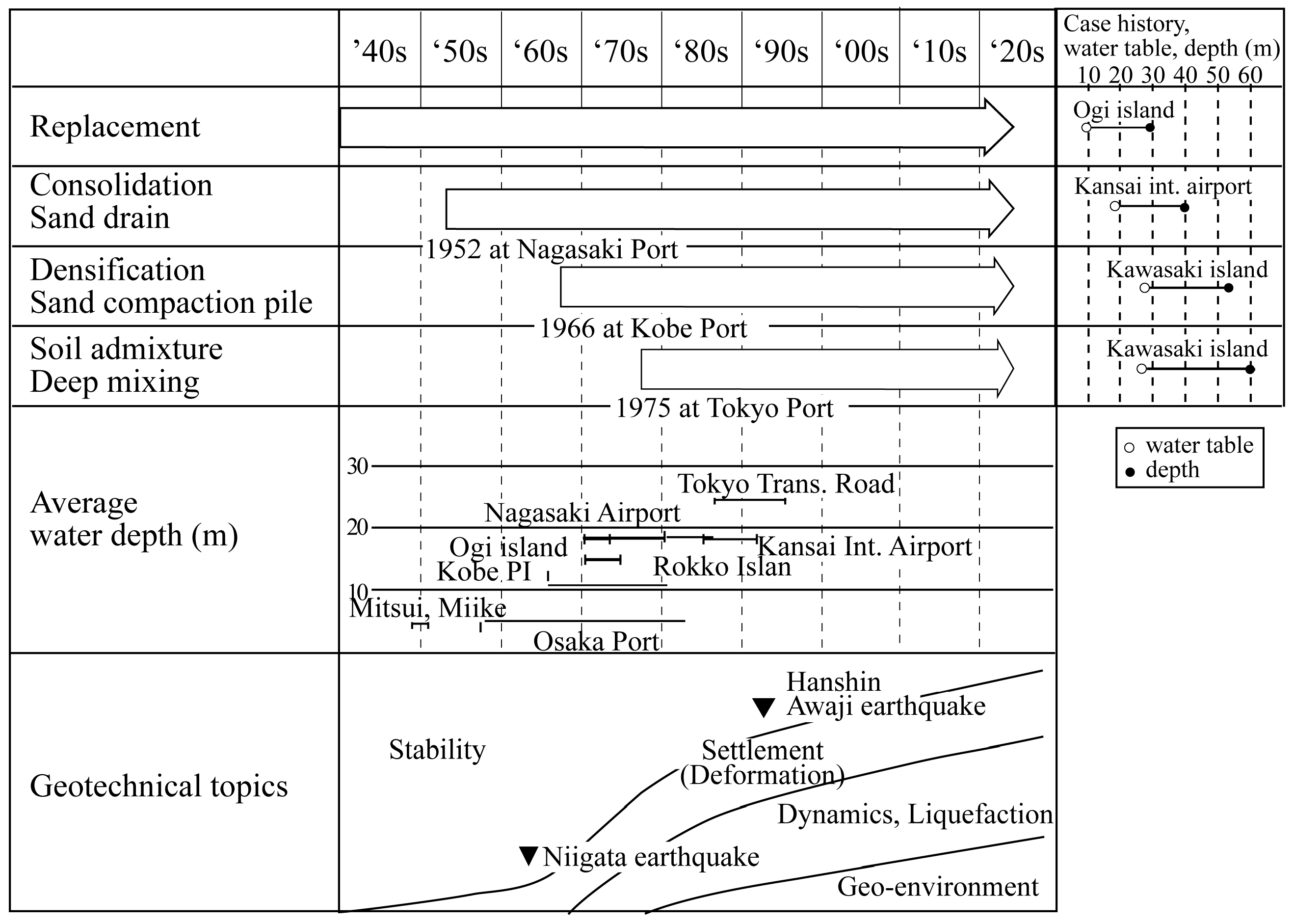
2. The Classification and Historical Development of Ground Improvement Techniques

When any type of infrastructure is constructed and soft soil is encountered, over an area, high levels of ground settlement and problems of stability failure and liquefaction are anticipated. Many types of ground improvement techniques have been developed and applied to many infrastructures as a countermeasure to these problems. Figure 1 shows the historical evolution of major ground improvement methods and the historical transactions in the field of geotechnical subjects in Japan [2]. Historically, a major geotechnical subject was the “stability problem” in the 1940s and the 1950s. It is not an exaggeration to say that the stability problem was the only issue that could be dealt with at that time due to insufficient development in geotechnical engineering and construction machinery. Replacement methods were frequently applied for stability problems, where the soft clayey soil stratum was entirely or partially excavated and replaced by sandy material prior to construction of the superstructure. After the development of consolidation theories in the 1940s, “ground settlement” became one of the main geotechnical subjects of discussion, together with the stability problem in the 1950s. In order to accelerate the consolidation process and to reduce the residual settlement, several improvement methods, which may be categorized into “consolidation”, were developed in the 1950s and the 1960s. Among them, the sand drain method was first applied at Nagasaki Port in 1952, which was followed by several applications in the 1950s to the 1960s. In order for ground settlement and deformation control to be applied, several densification methods were developed in the 1950s and the 1960s. In 1956, the first type of sand compaction pile (SCP) machine with a hammering device was developed in Japan for the densification of sandy ground (Figure 2). After various developments in machinery, the SCP method with a vibro-hammer was developed in 1959. Following its successful application to marine clay deposits, the SCP method has been applied not only to sandy ground but also to clay ground in many marine as well as on-land construction projects [3]. After the Niigata Earthquake in 1964, the dynamic behavior and liquefaction of sandy soil became one of the key issues in the field of geotechnical engineering. A lot of research efforts have been carried out on the dynamic properties of soil and countermeasures for liquefaction since then. In the period of rapid economic growth in the 1970s, the introduction of soil admixture stabilization was desirable for a rapid strength gain and high stiffness. In the 1970s, the deep mixing method (DMM), one of the in situ soil admixture techniques, was developed and put into practice (Figure 3). Due to the rapid strength increase of the soil, the DMM has been frequently applied to improve many kinds of foundation in marine and on-land construction [4]. In the 1970s and the 1980s, soil and groundwater contamination became one of the most pressing social problems. Since then, the management of waste landfill and contaminated sites has been a serious concern for those working in the discipline of geotechnical and geo-environmental engineering. This required the development of new ground improvement techniques to construct impermeable barriers for disposal sites and the enhanced beneficial use of dredged soft soil, subsoil and industrial waste, and also of any by-products. Many soil admixture stabilization techniques, such as the liquefied soil method, the light-weight soil method [5] and the pneumatic flow mixing method (ref. [6]) were developed and put into practice in the 1990s and the 2000s.
Many kinds of industrial waste materials and by-products have been beneficially used in many types of improved ground methods since the 1990s. In response to the growing awareness of carbon neutrality in recent years, it is necessary to further promote initiatives, and these include the use of materials with a low carbon footprint, the underground embedding of materials emitting carbon dioxide, the reduction in the amount of construction material used and the consequent reduction in the amount of construction energy used.

3. Recent Developments in and Application of Environmentally Friendly Ground Improvement Techniques

3.1. Soil Densification Techniques

(1)
Use of industry waste
The sand compaction pile method (SCP) is one of the densification techniques, in which many compacted sand piles are constructed in the ground to improve stability, for reducing ground settlement, and for preventing liquefaction [3]. Sand has been used in this method, but since the 1990s, many types of granular materials, including construction by-products such as slag [7], granular coal fly ash [8] and granular stabilized soil [9], have been beneficially used in this method. By promoting the beneficial use of these materials, these methods can provide a reduction in natural materials that can produce CO2 emission.
(2)
Discharge of biochar into the ground together with granular material
Recently, a new type of SCP method has been developed to achieve carbon dioxide reduction, in which biomass is discharged into the ground together with sand [10,11]. The sand is expected to increase the strength of the compacted pile, and the biomass is expected to store CO2 in the ground. Since the amount of carbon dioxide stored in the ground is overwhelmingly larger than the CO2 emitted in ground improvement work, this new technology can be described as being a “negative emission technology”. A field test revealed the high applicability of the biomass material, bamboo chips, in which the strength and shape were confirmed to be equivalent to those of conventional sand piles (Figure 4 and Figure 5 [11]). In the SCP method, a total of 5 kg CO2 per m3 of improved ground is emitted in construction when natural sand is used. In this new SCP method, however, carbon dioxide can be stored in the ground and the amount of CO2 emission can be decreased to −20 kg CO2 due to a larger amount of stored CO2 than the amount that was emitted during construction.

3.2. Soil Admixture Stabilization Techniques

Many soil admixture stabilization techniques have been developed and applied in many infrastructures since the 1970s due to their many benefits, such as rapid strength gain, wide applicability to many types of soil material, etc. In these techniques, cement is one of the materials most frequently used as a binder. However, about 800 kg of CO2 is emitted during the manufacturing 1 ton of cement, and the energy consumption related to cement material and cement production is about 4% of the total CO2 consumption in Japan. In cases where 200 kg cement per m3 soil is used for stabilization, 160 kg of CO2 is emitted. As the soil volumes to be stabilized are large in general, with the result that CO2 emission should also be large, it is desirable to use new types of binder that can reduce CO2 emission.
(1)
Use of materials with a low carbon footprint
One of the new binders is high-furnace-slag cement [12,13], which replaces the ordinary Portland cement (OPC) content to 30% with CaO and to 10% with SiO2 to compensate for the hydration reaction induced by the OPC. This new cement can reduce CO2 emission by 30% compared to OPC and 50% compared to furnace-slag cement type B. This cement has been applied to the shallow mixing method and the deep mixing method, in which the amount of CO2 emission can be reduced by about 51%, about 78 kg/m3 to 40 kg/m3, respectively.
The other new material is calcia, one of the by-products of the steel slag convertor. The calcia material is composed of calcia as the mother material, has a controlled chemical composition and is graduated. The calcia material can achieve a strength gain to about 200 kN/m2 through the dewatering effect and the calcium hydration effect. It has been applied to stabilize dredged soft soil for backfilling, shallow stabilization and land reclamation [14,15].
(2)
Mixing of biochar in the ground together with chemical binder
Recently, a new ground improvement method has been developed in which molten slag and biochar, as well as cement, are mixed with soil in situ [16,17,18]. The molten slag is produced by incinerating ash melted at a high temperature and cooled down, which is expected to improve the soil properties of clayey soil and can then reduce the required amount of cement for stabilization. The Japanese Industrial Standards (JIS) specified the quality and environmental safety requirements of the molten slag in 2006 to promote its utilization in civil engineering work and to prevent adverse impacts on the environment. Biochar is a material carbonized by the incomplete combustion of biomass raw materials, and functions to aid in the storage of carbon dioxide in the ground. By increasing the amount of biochar mixed, it is expected that carbon negativity will be achieved, in which the sum of CO2 emission reductions and fixed amounts exceeds the emissions, which can bring about a sort of decarbonized ground improvement method. In construction, molten slag, biochar and cement are spread on the ground and mixed and compacted to build a stiff, shallow layer (Figure 6 [17]). The amounts of molten slag and biochar are 550 to 1750 kg/m3 and 10 to 30 kg/m3, which can reduce the amount of cement that needs to be used to about 60% of the cement used in the existing methods, as shown in Figure 7.
(3)
Beneficial use of spoil
Another method is to reduce and beneficially use spoil, which can reduce the required amount of binder and reduce the construction energy used. A large amount of cement slurry is usually injected into the ground using soil admixture stabilization techniques. Cement slurry with a low water-to-cement ratio is preferable for strength increase. However, this leads to less fluidity of the slurry, which requires high-capacity pumping machinery to inject it into the ground. Several techniques have been developed to maintain high fluidity of the cement slurry with a low water-to-cement ratio, in which chemical additives are mixed with the slurry [19].
Another method is the injection of an air bubble together with the cement slurry. The air bubble functions as a sort of ball bearing to increase the fluidity of the cement slurry The amount of cement slurry required can be reduced to achieve design strength, which can help to reduce the amount of cement, and the amount of energy used for cement production and transportation [20].
In the case of DMM, particularly the jet grouting method (Figure 8), a large amount of spoil, a mixture of in situ soil and cement slurry, flows out to the ground surface during construction. It is usually transported to a disposal site for dumping, which requires a lot of energy. In order to reduce the volume of spoil to be dumped, a new DMM is being developed in which the spoil is dissolved, separated and classified, and the soil particles in the fluid are used as mixing material, after adjusting its particle size distribution [21].
(4)
Reduction in stabilized soil volume
Grid-type DM-improved ground is often applied for liquefaction mitigation [22]. In a single stroke of the deep mixing procedure, circular-shaped columns are constructed and they are overlapped together to create walls in a grid shape to improved the piece of the label, as shown in Figure 9. In the case of the jet grouting technique, the circular-shaped column is constructed by injecting high-pressure binder slurry, and its column diameter is controlled by the air pressure and rotation speed of the mixing shaft; a low rotation speed creates a large-diameter column in the jet grouting method, and usually, they are kept constant to create a circular column shape. It is desirable to construct a rectangular-shaped column rather than a circular-shaped column for economic reasons. In the new jet grouting methods, the rotation speed of the shaft is controlled and changed to create an improved rectangular shape on the ground, as shown in Figure 10 [23,24,25,26].
(5)
Reduction in CO2 emission during execution
Another effort has been made to reduce CO2 emission by reducing the energy used in ground improvement works. The deep mixing method, for example, requires a large amount of energy to bring about the movement of mixing tools and the rotation of each mixing tool, and for producing cement slurry and pumping it into the ground. In order to reduce the construction energy expended, a new DM vessel was developed, as shown in Figure 11, which distributes the energy of an electric generator by installing a multiple-diesel engine; this transfers the generated energy through the downward movement of mixing tools, and beneficially uses exhaust heat in generating energy for air conditioning, and generates energy via solar power and wind turbines [27,28].

4. Concluding Remarks

In response to natural disasters such as earthquakes and landslides, many ground improvement techniques have been developed and applied to improve the physical and mechanical properties of soil to achieve stability improvement, ground settlement control, reinforcement, liquefaction prevention, etc. These techniques use a lot of natural materials and industrial products. In order to reduce the environmental impact and the costs of these methods, many kinds of industrial waste and by-products have been beneficially used in many types of improved ground methods. In response to the growing awareness of carbon neutrality in recent years, it is necessary to further promote initiatives such as the beneficial use of industrial waste and by-products, and the development of new materials and construction methods, to reduce CO2 emission. It is also expected that various biomass materials will be used in the application of improved ground techniques to enhance “negative emission technology”.
As the environmentally friendly ground improvement technologies introduced above are often a little more expensive than conventional technologies, it is necessary to reduce the costs of these techniques. On the other hand, society must also accept and share some of the costs for environmental protection.
In this paper, some of the recently developed ground improvement techniques are introduced briefly. It is to be expected that these will be further developed and applied to contribute to the reduction in carbon dioxide emissions.

Funding

This research received no external funding.

Institutional Review Board Statement

The study did not require ethical approval.

Conflicts of Interest

The author declares no conflict of interest.

References

  1. Ministry of the Environment, Japan, Greenhouse Gas Inventory Office of Japan (GIO), CGER, NIES: National Greenhouse Gas Inventory Report of Japan. 2013, p. 782. Available online: https://www.enecho.meti.go.jp/en/category/special/article/detail_164.html (accessed on 31 July 2023).
  2. Tsuboi, H. Ground Improvement Techniques for Marine Ground. In Proceedings of the 39th National Symposium on Geotechnical Engineering, Niigata, Japan, 7–9 July 1994; Japanese Society of Soil Mechanics and Foundation Engineering: Tokyo, Japan, 1994; pp. 13–18. (In Japanese). [Google Scholar]
  3. Kitazume, M. The Sand Compaction Pile Method; CRC Press, Taylor & Francis: Boca Raton, FL, USA, 2005; 232p. [Google Scholar]
  4. Kitazume, M.; Terashi, M. The Deep Mixing Method; CRC Press, Taylor & Francis Group: Boca Raton, FL, USA, 2013; 410p. [Google Scholar]
  5. Tsuchida, T.; Egashira, K. The Lightweight Treated Soil Method-New Geomaterials for Soft Ground Engineering in Coastal Areas; CRC Press: Boca Raton, FL, USA, 2004; 136p. [Google Scholar]
  6. Kitazume, M. The Pneumatic Flow Mixing Method; CRC Press, Taylor & Francis Group: Boca Raton, FL, USA, 2016; 233p. [Google Scholar]
  7. Kitazume, M.; Minami, K.; Matsui, H.; Naruse, E. Field test on applicability of copper slag sand to sand compaction pile method. In Proceedings of the 3rd International Congress on Environmental Geotechnics, Lisboa, Portugal, 7–11 September 1988; Volume 2, pp. 643–648. [Google Scholar]
  8. Okeno, K.; Saito, N.; Hyoudo, M.; Nakata, S.; Murata, M. Improved characteristics of granulated coal fly ash in marine SCP field test, Improvement effect. In Proceedings of the 60th Annual Conference of the Japan Society of Civil Engineers, Kyoto, Japan, 21–24 October 2001; pp. 400–401. (In Japanese). [Google Scholar]
  9. Fujiwara, T.; Tanaka, H.; Kadota, M.; Ohiso, Y.; Kurata, T. Field test of static compaction improved method by granulated excavated-soil. In Proceedings of the 35th Annual Conference of the Japanese Society of Soil Mechanics and Foundation Engineering, Sapporo, Japan, 13–15 September 2000; pp. 1425–1426. (In Japanese). [Google Scholar]
  10. Yamamoto, K.; Satou, K.; Watanabe, E.; Fijikawa, T.; Nunokawa, H.; Koga, C. Compaction and mechanical properties of bamboo chip and RC mixed material for SCP method. In Proceedings of the Annual Conference of Japan Society of Civil Engineers, Hiroshima, Japan, 14–15 September 2023; pp. 369–370. (In Japanese). [Google Scholar]
  11. Home Page of Fudo Tetra Corporation. 2023. Available online: https://www.fudotetra.co.jp/news/ (accessed on 31 July 2023).
  12. Yonezawa, T.; Sakai, E.; Koibuchi, K.; Kanda, T.; Dan, Y.; Sagawa, T. High-Slag Cement and Structures for Substantial Reduction of Energy and CO2. In Proceedings of the 3rd International Conference on Sustainable Construction Materials and Technologies, Kyoto, Japan, 18–21 August 2013; pp. 1–10. [Google Scholar]
  13. Kono, T.; Tsugawa, S.; Yoshida, T.; Sato, E.; Yonezawa, T.; Taki, S.; Kinoshita, M.; Nito, N. Characteristics of soil improvement using high-volume blast furnace slag cement (part 1). In Proceedings of the 45th Annual Conference of the Japanese Geotechnical Society, Matsuyama, Japan, 8–10 August 2010; pp. 565–566. (In Japanese). [Google Scholar]
  14. Tanaka, Y.; Yamada, K.; Ookubo, Y.; Shibuya, T.; Nakagawa, M.; Akashi, Y.; Ichimura, M.; Yamagoshi, Y. Reclamation and evaluation of dredged soil with converter slag. J. Geotech. Eng. Jpn. Soc. Civ. Eng. 2021, 68, 486–491. (In Japanese) [Google Scholar]
  15. Yamagoshi, Y.; Akashi, Y.; Nakagawa, M.; Kanno, H.; Tanaka, Y.; Tsuji, T.; Imamura, T.; Shibuya, T. Reclamation of the artificial ground made of dredged soil and converter slag by using pipe mixing method. J. Geotech. Eng. Jpn. Soc. Civ. Eng. 2013, 69, 952–957. (In Japanese) [Google Scholar]
  16. Furuta, S.; Kinugawa, Y.; Takagi, S.; Tamura, S.; Nishida, M.; Nagasawa, M.; Tsuchiya, H.; Maeda, T. A decarbonizing soil improvement method using molten slag and biochar (No.1): Laboratory test. In Proceedings of the 78th Annual Conference of the Japan Society of Civil Engineers, Hiroshima, Japan, 11–15 September 2023. submitted (In Japanese). [Google Scholar]
  17. Nishida, M.; Nagasawa, M.; Tsuchiya, H.; Maeda, T.; Furuta, S.; Kinugawa, Y.; Takagi, S.; Tamura, S. A decarbonizing soil improvement method using molten slag and biochar (No.2): In-situ test. In Proceedings of the 78th Annual Conference of the Japan Society of Civil Engineers, Hiroshima, Japan, 11–15 September 2023. submitted (In Japanese). [Google Scholar]
  18. Home Page of Shimizu Corporation. Available online: https://www.shimz.co.jp/company/about/news-release/2023/2022061.html (accessed on 31 July 2023).
  19. Hirano, S.; Mizutani, Y.; Nakamura, H.; Shimomura, S.; Sasada, H. Quality improvement of deep mixing method by dispersant additives. In Proceedings of the 50th Annual Conference of the Japanese Society of Soil Mechanics and Foundation Engineering, Matsuyama, Japan, 19–21 September 2015; pp. 881–882. (In Japanese). [Google Scholar]
  20. Okabe, M.; Kawamura, K.; Masuda, K.; Seki, T. Ingenious device of site management in ground improvement work by CI-CMC method. J. Jpn. Soc. Soil Mech. Found. Eng. 2011, 59, 16–19. (In Japanese) [Google Scholar]
  21. Kenbo, H. Current Status, Issues and Prospects of Jet Grouting Method; Kisoko, Sougou Doboku Kenkyusho. Co., Ltd.: Tokyo, Japan, 2017; pp. 7–10. (In Japanese) [Google Scholar]
  22. Tokimatsu, K.; Mizuno, H.; Kakurai, M. Building damage associated with geotechnical problems. Soils Found. 1996, 36, 219–234. [Google Scholar] [CrossRef] [PubMed] [Green Version]
  23. Shinsaka, T.; Yamazaki, J.; Nakanishi, Y.; Komiya, K. Quality Control and Shape Control Techniques in Jet Grouting. In Proceedings of the International Foundations Congress & Equipment Expo, IFCEE 2018, Orlando, FL, USA, 5–10 March 2018. [Google Scholar]
  24. Shinsaka, T.; Yamazaki, J. Development of high-speed type jet grouting method. In Proceedings of the Geotechnics for Sustainable Development–Geotec Hanoi 2013, Hanoi, Vietnam, 28–30 November 2013. [Google Scholar]
  25. Tsuchiya, T.; Abe, H.; Komatsu, K. A study on altering the cross-sectional shape and altering the quality of the jet grout column. In Proceedings of the Grouting 2017: Jet Grouting, Diaphragm Walls, and Deep Mixing, Honolulu, HI, USA, 9–12 July 2017; pp. 21–30. [Google Scholar]
  26. Harada, K.; Ohbayashi, J.; Matsumoto, J.; Kubo, Y.; Akima, T. New ground improvement technologies under restricted conditions in Japan. In Proceedings of the 15th Asian Regional Conference on Soil Mechanics and Geotechnical Engineering, Fukuoka, Japan, 9–13 November 2015; pp. 1165–1170. [Google Scholar]
  27. Imamura, K.; Ishiguro, K. Environmentally friendly deep mixing vessel, Kokaku. Constr. Mech. 2010, 37–41. (In Japanese) [Google Scholar]
  28. Saegusa, H.; Asada, H.; Taguchi, H.; Fukawa, H.; Hirota, S. Case study on application of deep mixing method in Kinjo area of Nagoya port. In Proceedings of the DFI Deep Mixing Conference 2021, Online, 1–17 June 2021; pp. 225–232. [Google Scholar]
Figure 1. Historical evolution of major ground improvement methods and the historical transactions in the field of geotechnical subjects in Japan [2].
Applsci 13 08985 g001
Figure 2. Sand compaction pile machine in the 1950s (courtesy of the Fudo Tetra Corporation).
Applsci 13 08985 g002
Figure 3. Deep mixing machine in the 1970s.
Applsci 13 08985 g003
Figure 4. Sand and biomass material (bamboo chips) [11] (courtesy of the Fudo Tetra Corporation).
Applsci 13 08985 g004
Figure 5. Strength profile along depth [11].
Applsci 13 08985 g005
Figure 6. Shallow mixing machine [17] (courtesy of the SHIMIZU CORPORATION).
Applsci 13 08985 g006
Figure 7. Relationship between amount of binder and strength [17].
Applsci 13 08985 g007
Figure 8. Jet grouting machine (courtesy of the Chemical Grouting Co., Ltd., Tokyo, Japan).
Applsci 13 08985 g008
Figure 9. Grid-type DM-improved ground.
Applsci 13 08985 g009
Figure 10. Rectangular-shaped stabilized soil column constructed via jet grouting method (courtesy of the Chemical Grouting Co., Ltd.).
Applsci 13 08985 g010
Figure 11. A new deep mixing vessel (courtesy of the Toa Corporation, Tokyo, Japan).
Applsci 13 08985 g011
Disclaimer/Publisher’s Note: The statements, opinions and data contained in all publications are solely those of the individual author(s) and contributor(s) and not of MDPI and/or the editor(s). MDPI and/or the editor(s) disclaim responsibility for any injury to people or property resulting from any ideas, methods, instructions or products referred to in the content.

