Abstract
More and more commonly, manipulators and robots equipped with effectors are used to replace humans in the implementation of tasks that require significant working abilities or are used in dangerous zones. These constructions have considerable ranges and are capable of carrying heavy loads. The specificity of the tasks performed with the use of mentioned devices requires their control by a human. Intuitive tracking systems are used to control them. Problems in their use result from the kinematic amplification between the effector and the operator’s hand. Proper design of the drive and control systems for these manipulators requires knowledge of the maximum velocities of the manipulator’s effectors, which significantly depend on the scale ratio. The article presents the results of the effector’s velocity movements while performing a specific task by the operator’s hand with different velocities and scale ratios.
1. Introduction
Manipulators replacing direct human activity are increasingly used in the world. They have been used both in medicine as surgical manipulators [1,2,3], and in military applications, rescue services, or the construction industry in the form of specialist manipulators or equipment [1,4,5]. In dangerous scenarios such as chemical plants [6], disaster sites [7], explosives demolition [8,9], and teleoperated manipulators are needed. Robotic teleoperation satisfies the demands of scenarios in which human access is dangerous but human intelligence is required [10,11]. For this work, the operator is required to constantly control the position of the effector using the system HMI (Human–machine Interface) consisting of visualization system (cameras and displays or goggles) and control devices.
The efficiency of teleportation dramatically depends on the quality of the control system and operation space visualization. All manipulator movements are executed on the effector placement observation, but very often the quality of the control system limits the operation speed and productivity.
As the most common human–machine interface controllers, which are easy to use to provide simple commands in teleoperation tasks, keyboards, joysticks, gamepads, mouses, or 3D mouses are used [12,13,14]. These devices force human operators to learn how to use them because their usage is unnatural. It is problematic for the operation of the manipulator with higher DOF (Degrees of Freedom) because the operators have to generate the command for every joint motion of the manipulator. It demands long operator training and limits the productivity and efficiency of operation [15]. For those reasons, more complex taskmaster–slave devices are used like master exoskeleton, optical motion capture technology, data gloves or gloves with markers, and haptic devices [13,16,17,18]. New solutions improve the control efficiency and enable higher speed of effector motions [19,20,21].
The use of this type of control is particularly desirable and important if an inexperienced operator controls the manipulator. Thanks to this, operators are able to achieve high control efficiency comparable to experienced operators in a relatively short time [22,23,24].
It is very important for operations with heavy, high lifting capacity, and long reach manipulators equipped with hydraulic drive systems. The modern control system can increase their movement velocity and overall productivity. In such construction, the speed limit should be adapted to human perception and the possibility of system control. An additional problem is the size ratio. Due to the large working area, there is a large-scale ratio between the HMI size and the effector workspace of these manipulators [25].
Knowledge of the influence of size ratio on the permissible effector velocities of these manipulators is essential for the effective design of their drive systems and power demand. This will allow to increase the velocity of movements, overall efficiency, and effector movement accuracy [26].
The main element of the intuitive control system is a suitably shaped track device with various types of construction solutions [26,27,28,29,30]. Starting from specially shaped structures with the same kinematic structure as the controlled manipulator [26], through parallel structures used in medical applications [29,30] up to those adapted to the operator’s upper limb [27,28]. The effectiveness of using this type of control systems depends on the operator’s perception and scale ratio and the velocity and acceleration of the operator’s hand [31]. According to [32] presented research involving moving the cursor on the monitor screen between points spaced every few centimeters, using a tracking device with haptic feedback for scale ratios 1:1, 1:2, and 2:1, for the 1:2 size ratio, the time increased by 30% compared to the 1:1 size ratio, while in the case of the 2:1 size ratio, there was no significant difference in this aspect. Moreover, the ability to identify obstacles when controlled with a tracking device depends on the perception and position of the operator’s hand [33].
An overlooked problem when controlling manipulators using a tracking device is the size ratio [26] between the movement of the operator’s hand and the displacement of the manipulator effector, which has a direct impact on the value of its velocity. This problem does not seem to be so important when controlling surgical manipulators. This is due to the small-scale ratio, for which the effector makes less movement in relation to the operator’s hand [29,34]. The velocity of the movements in this case is of little importance. The basic problem is to ensure the accuracy of the effector’s movement of the controlled manipulator.
It is confirmed in the research of hydraulic excavators [35], describing the efficiency of conventional control system and tracking devices. During the research, the effort of the operators was also compared using a survey NASA-TLX. On its basis, the problem of the operator’s psychophysical load due to the oscillations of the excavator’s bucket was noticed. They resulted from small, uncontrolled movements of the operator’s hand during control with the tracking device. The amplified vibration of the operator’s hand by the manipulator control system limited the efficiency of operation. On this basis, it was found that the scale ratio may have a significant impact on the efficiency of operation for manipulators with a large working area, such as foundry manipulators, EOD robot manipulators, arms of hydraulic excavators, or demolition equipment. These conclusions are confirmed by the research presented in the paper [36]. The authors compare a conventional control system of the excavator with two tracking devices using position control and rate control. They found that both systems based on a tracking device improve the velocity and accuracy of task realization more than twice as compared to the conventional type of control. However, according to the subjective assessments of the test participant, the use of the position control system is more intuitive in operation in relation to the rate control system, although the implementation of long movements may cause early stress on the user’s arm and then increase his frustration. To limit the impact of the operator’s hand vibration on the efficiency of the manipulator, a hybrid control method was proposed [26]. Rate control was used for the rotation of the excavator swing and position control was for the positioning of the working equipment. In this way, the intuitive control of the working equipment was maintained and the problem with the control of the excavator swing, whose range of movement is 360°, was eliminated. The research [31] shows that the direction of the operator’s hand movement has no significant effect on the velocity. However, there are significant differences in the maximum values of the operator’s hand velocity during reaching movements (average maximum speed 1 m/s) and precision movements (average maximum speed 0.5 m/s).
The research results so far take into account the accuracy and velocity of task execution using intuitive tracking control systems. The discussed issues concern the impact of haptic feedback on the effectiveness of control and adjusting the control using the tracking device to the operator’s hand. Most of the research on the HMI device relates to the control of manipulators with a small working area, where the size ratio does not affect their work efficiency. Manipulators with a large working area need other solutions.
Based on subjective assessments, the impact size ratio on the efficiency of work with these manipulators was found, but this information is vague and omitted in further analyses. There is also no information on the velocity of the effectors of manipulators with a large working area depending on the size ratio and the perception of the operator. In order to increase the effectiveness and efficiency of manipulators with a large working area, the operator’s perception and psycho-physical capabilities should be fully used due to the size ratio. Therefore, in the paper, an assessment of the impact of the range of the manipulator and size ratio on the velocity of the manipulator effector was undertaken, due to the perception of the operator. Research [12,13,17] shows the possibility of creating controllers that allow the manipulator to achieve speeds consistent with hand movements with imperceptible delays. The use of these possibilities requires the design of an appropriate drive system. The research results can be particularly useful for the development of human control interface, which are currently under intensive development [37].
Since the knowledge of the maximum velocities of the effector and individual components is necessary for the proper design of drive systems, the research was focused on long distance movement. In order to increase the control accuracy, according to [16], the tests were carried out using the entire range of the human hand. Determining the speed of the effector’s movements will enable the proper selection of drive system components.
2. Materials and Methods
2.1. Nomenclature
Because more specific terms, symbols, and abbreviations are utilized in the article, the nomenclature is shown in Nomenclature at below.
2.2. Experimental Setting and User Task
In order to determine the speed of the effector, a lab stand was built in which the movement of the effector (slave) was simulated by the movement of the laser spot on the screen. The operator’s task was to move the spot between the markers by hand-moving the lever with the laser pointer (Figure 1) which was imitating the master controller.
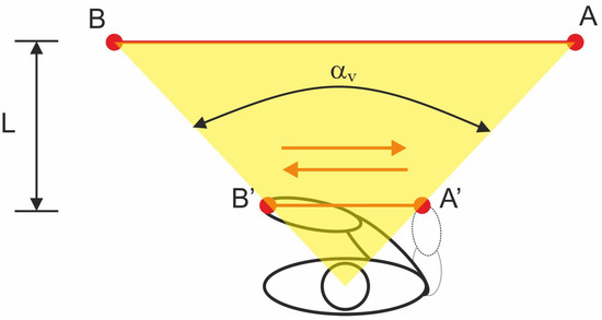
Figure 1.
Scheme showing the idea of research on the impact of size ratio on the velocity of the operator’s hand movement, described in the main text.
Each subject moved, using his hand, the laser spot (effector) displayed on the screen from point A to B (right to left) and back from B to A (left to right) in a straight line.
Changing the operator’s distance from the screen made it possible to change the size ratio. Horizontal, lateral movement of the operator’s hand was about 800 mm and was in the comfort zone according to [38]. During hand movement viewing angle was about αv = 60°, for which human is capable of recognizing colors [39]. The research was conducted for distances 2, 4, and 8 m, which gave size ratio K = 2.5; K = 5 and K = 10. These are typical size ratios during positional control for manipulators with a large working area [23,24,31,40,41,42,43].
In the first stage, the subjects performed manipulative tasks at a velocity they considered normal–normal movements. In the second stage, the subjects performed the tasks with the maximum velocity possible for them—fast movements. Normal movements were defined as those that allow the hand to be moved at a subjective velocity that ensures stable hand guidance during the performance of a defined task. Fast movement is considered to be one in which the hand is moved at a velocity that ensures the fastest possible execution of the task.
All subjects performed normal and fast movements with their dominant hand. Each subject performed trials with six normal and six fast movements for each. Therefore, the number of recorded, normal movements was 540 (30 subjects × 6 movements × 1 direction × 3 size ratio) and for fast movements was the same number of records 540 (30 subjects × 6 movements × 1 direction × 3 size ratio). This test was measured after two practice trials.
According to [31], during the realization of human hand movements the acceleration phase (pa), the steady motion phase (ps), and the deacceleration phase (pd) can be observed. Therefore, the following indicators were adopted to evaluate the research results (Figure 2):
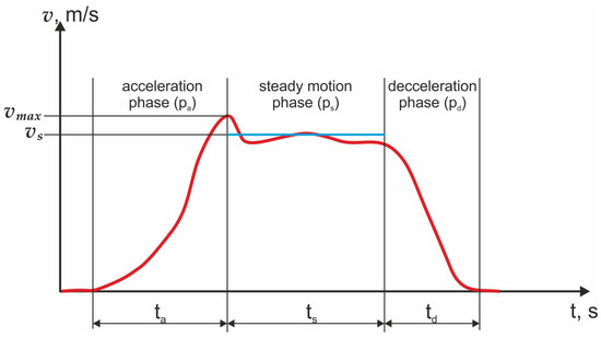
Figure 2.
The scheme of indicators to evaluate experimental research.
- -
- the maximum velocity of the operator’s hand movement for all size ratios from the entire range for normal and fast movement—,
- -
- the average effective velocity of the operator’s hand movement for all size ratios for the steady motion phase for normal and fast movement—;
- -
- the average value of acceleration phase time duration (pa) for all size ratios from the entire range for normal and fast movement—;
- -
- the average value of steady motion phase time duration (ps) for all size ratios from the entire range for normal and fast movement—;
- -
- the average value of deacceleration phase time duration (pd) for all size ratios from the entire range for normal and fast movement—.
The steady motion phase (ps) is the phase during which the velocity of the operator’s hand movement does not change more than 5%.
2.3. Experimental Stand
The idea of the research stand work is to change the movement of the operator’s hand—|A′B′|, during rectilinear movement, to the movement of the laser point (effector) displayed on the screen |AB| by a constant size ratio—K value (Figure 3).
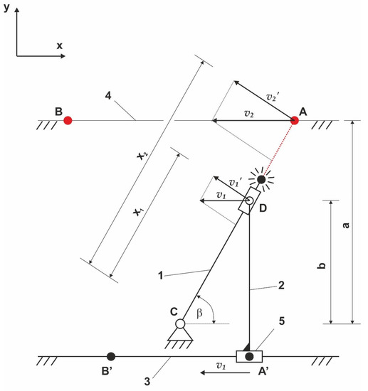
Figure 3.
The research stands kinematic scheme, described in the main text.
The operator, moving the joystick (5) from point A′ to B′, rigidly connected to the lever (2) along the guide (3), and forces the lever (1) to rotate in relation to point C. At the end of the lever (1) there is a laser pointer whose direction of the outgoing laser point is consistent with the longitudinal direction of the lever (1). The laser point falls on the screen (4) creating point A. The projection of the screen surface (4) onto the xy plane is parallel to the guide (3). The kinematics developed in this way allows for a proportional increase in the velocity of the laser point (effector) on the screen relative to the velocity of the operator’s hand according to the equation:
where K = a/b—scale ratio value.
Point D in the developed mechanism moves with a complex movement resulting from the translational movement of the lever (2) and a rotating lever (1) relative to point C.
Assuming linear velocities , depends on the angular velocity of the lever (1) ω and distances and (Figure 3) according to Equations (2) and (3):
where ω—angular velocity of the lever (1), —the distance between points C and D, and —the distance between points C and A.
Depending on the velocities , on , and the distances and on the dimensions b and a (Figure 3) according to Equations (4)–(7):
and after substituting them to (2) and (3) and transforming, the equation for velocity in function was obtained:
The ratio of the distance between point C and the screen surface (a) and the lever mounting point D (b) is the value of the size ratio K.
Based on the developed kinematic structure (Figure 3), a research stand was designed, and its model and idea of the operation of it are shown in Figure 4.
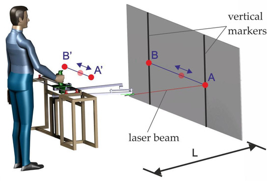
Figure 4.
The research stand 3D model.
The constructed research stand, based on the adopted assumptions, is shown in Figure 5.
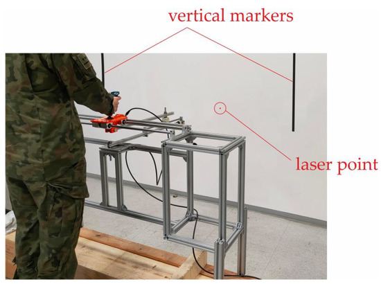
Figure 5.
Realization of exemplary research.
The basic measuring element of the research stand, which allowed to determine the value of the operator’s hand movement, was the absolute magnetic sensor LA10 manufactured by Kuebler with a measuring accuracy of 0.03 mm over the entire working range [44].
2.4. Participants
Two-step human hand movement velocity testing for different size ratios was conducted in a group of 30 people (male) aged 21 to 37 years with a height of 165–194 cm. The most numerous groups of respondents (22 people) were students aged 21–22.
2.5. Statistical Analyses
The value of the operator’s hand displacement in time was obtained directly from the research. Based on the displacement, the velocity of the human hand and effector movement was determined for the normal and fast movements. The values of the velocity of the human hand and effector for both steps of research were determined based on the backward differential quotient. The relationship that allows for determining the velocity takes the form [45,46]:
where xi—hand displacement, and —the time corresponding to the hand movement xi.
In order to determine the level of variability of the human hand velocity value for normal and fast movements, depending on the operator who performs the movement, the sample standard deviation—σ and the coefficient of variation—Cv were determined.
The sample standard deviation was determined using the equation [45,46]:
where —the value of a given random variable in the sample, —arithmetic mean of the sample, and n—number of elements in the sample.
The coefficient of variation— was determined using the equation [45,46]:
3. Results
The Shapiro–Wilk test was used to check the normality of the distribution. The significance level α = 0.05 was adopted. For 30 people tested according to the data in the tables of coefficients for the Shapiro–Wilk test [47], the critical value is . The normality of the RMS velocity distribution for fast and normal movements was checked for size ratio K = 2.5, K = 5, K = 10. The following results were obtained:
- fast movements:
- –
- for K = 10: W = 0.947; p = 0.144;
- –
- for K = 5; W = 0.952; p = 0.201;
- –
- for K = 2.5; W = 0.964; p = 0.390;
- normal movements:
- –
- for K = 10; W = 0.938; p = 0.181;
- –
- for K = 5; W = 0.957; p = 0.269;
- –
- for K = 2.5; W = 0.964; p = 0.406.
The obtained results of the Shapiro–Wilk test indicate that the distribution of the obtained test results is close to normal. Power analysis of the ANOVA test performed for normal movements (α = 0.05 and RMSSE (Root Mean Square Standardized Effect) equal 0.9273), and fast (α = 0.05 and RMSSE = 0.6031), showed that the number of trials is sufficient to show the difference between the velocity of movement of the effector (E) and the operator’s hand (H) depending on the size ratio (K) and ensure the test power of 80%. The number of trials is also sufficient (test power over 80%) necessary to show the differences between the velocity of movement depending on its direction (from A to B or from B to A) for different size ratio of normal movements (ANOVA for α = 0.05; RMSSE = 0.8509) and fast (ANOVA for α = 0.05; RMSSE = 0.5857).
Example waveforms of velocity changes for one of the operators obtained as a result of research for normal and fast movements of the operator’s hand for three size ratio values are shown in Figure 6 and Figure 7.
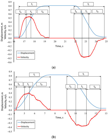
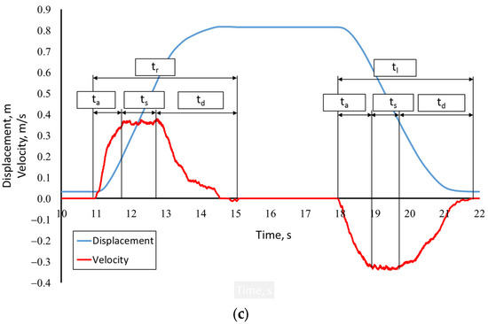
Figure 6.
An example courses of changes in displacement and velocity for the normal hand movement; (a)—an example course for K = 2.5; (b)—an example course for K = 5; (c)—an example course for K = 10; where p is the phase of the movement.
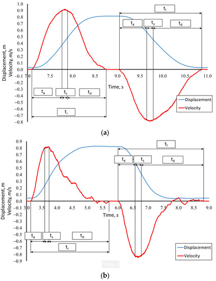
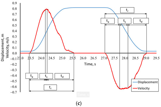
Figure 7.
An example courses of changes in displacement and velocity for the fast hand movement; (a)—an example course for K = 2.5; (b)—an example course for K = 5; (c)—an example course for K = 10; where p is the phase of the movement.
Analyzing the presented waveforms (Figure 6 and Figure 7), two stages of the movement can be distinguished. The first stage is related to the movement from A to B (Figure 1)—p1(jK) and the second stage is associated with the movement from B to A (Figure 1)—p2(jK). At each stage of the movement, you can observe the acceleration phase—pAi(jK), steady motion phase—pSi(jK) and the deceleration phase—pDi(jK), where “i” is the stage of movement (1—from A to B, 2—from B to A), “j” indicates the type of movement performed (N—normal movement and F—fast movement) and “K” is the size ratio. Note that as the size ratio value decreases and the movement velocity increases the steady motion phase decreases. For fast, low-size ratio movements, it may fade away.
In order to check whether there are significant differences in the velocity of movements depending on the turn (movement from A to B compared with B to A), ANOVA F analysis was performed for the analyzed reinforcements and types of movement. The analysis showed that the direction of movement does not significantly affect the RMS velocity. In the case of ANOVA F for the RMS velocity in normal movements obtained:
- for K = 10—F (1,118) = 0.256, p = 0.626,
- for K = 5—F (1,118) = 0.011, p = 0.916,
- for K = 2.5—F (1,118) = 0.050, p = 0.828.
ANOVA F for the RMS velocity in fast movements showed:
- for K = 10—F (1,118) = 0.319, p = 0.587,
- for K = 5—F (1,118) = 1.444, p = 0.315,
- for K = 2.5—F (1,118) = 1.277, p = 0.291.
Due to the lack of significant differences between the RMS velocity values of the movements depending on the turn, the analysis of the significance of changes in the remaining parameters was omitted. The entire movement was subjected to further analysis, averaging the achieved velocity of movements. A summary of the time duration of the acceleration phase—ta, steady motion phase—ts, and the deceleration phase—td, depending on the scale ratio—K, is presented in Figure 8.
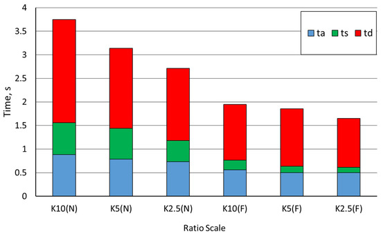
Figure 8.
Summary of durations ta, ts, and td in whole movement; N—normal movement, F—fast movement.
Based on the presented graph (Figure 8), it can be concluded that the deacceleration phase (pd) has the largest share in all completed movements. Its duration is 2.2 s for normal movement with K = 10 and 1 s for fast movement with K = 2.5. The steady motion phase duration (ps) decreases as the size ratio decreases. For normal movements, for K = 10, the average duration of the steady motion phase—ts was 0.7 s, while for fast movements with K = 2.5, this time was only 0.1 s. Therefore, it is likely that for a small size ratio, the steady motion phase may not be present, which is consistent with [31].
The list of recorded values of maximum movement velocities and effective RMS velocities in the steady motion phase obtained during the research for all size ratios in relation to the movement of the operator’s hand (H) and the movement of the effector (E) is shown in Figure 9. They used a box plot to show the distribution of a set of data. In a box plot, numerical data is divided into quartiles, and a box is drawn between the first and third quartiles, with an additional line drawn along the second quartile to mark the median. The minimums and maximums outside the first and third quartiles are depicted with lines, which are often called whiskers. The mean value is marked by “x” symbol.
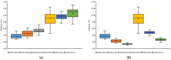
Figure 9.
Summary of RMS velocity values in the steady motion phase: (a) normal and fast operator hand movements for the tested size ratios and (b) normal and fast effector movements for the tested size ratios.
Analyzing the graphs (Figure 9), it can be seen that there are clear differences in the obtained velocities for normal and fast movements. The RMS velocity in normal movements is 43 to 53% lower when comparing the values from the appropriate size ratio with fast movements. The ANOVA F analysis indicated that the value of the size ratio affects the value of the RMS velocity—F(2, 357) = 43.58 p ≈ 0 and the maximum velocity—F(2, 357) = 27.22; p ≈ 0 in normal movement. In the case of fast movements, the relation of RMS velocity—F(2, 357) = 8.16; p = 0.0006 and maximum velocity—F(2, 357) = 6.00; p = 0.004 from size ratio is also significant.
The averaged RMS velocity values for normal and fast hand movements (H) were smaller with the increase in size ratio. For size ratio K = 10, the RMS velocity of normal movements was close to 0.25 m/s, while for size ratio K = 5, this velocity was 21% higher, and for size ratio K = 2.5 it was 41% higher. In the case of fast movements, the RMS velocity for size ratio K = 10 was 0.53 m/s and was over 50% higher than for normal movements. The RMS velocity of fast movements obtained for the size ratio K = 5 was 0.55 m/s, while for the size ratio K = 2.5, it was 0.62 m/s. The maximum velocity in normal movements was 0.56 m/s and was reached for K = 2.5. The maximum velocity in fast movements was almost two times higher than in normal movements and amounted to 1.1 m/s.
In the case of the velocity of movement of the effector (E), it can be seen that the velocity of movement increases significantly with the increase in size ratio, contrary to the case in the movement of the operator’s hand (H). Comparing the value of the maximum velocities of the effector for the size ratio of K = 10 to the maximum velocities for K = 2.5, a three-fold increase can be observed. The maximum effector movement velocities obtained from the tests reach nearly 10 m/s and were recorded during the implementation of fast movements for K = 10. In the case of normal movements, the maximum obtained velocities reached 4.0 m/s and they were also obtained for the highest value of the size ratio. The movement velocity of the effector, with different size ratio, refer to the real possibilities of conscious control of the manipulators with different ranges by operators.
Based on the research results of normal and fast movements of the effector (E) and the operator’s hand (H), the average values of the maximum velocities and the average RMS velocities for the entire movement and the RMS velocities for the steady motion phase—pS. The determined parameters are shown in Table 1.

Table 1.
Values of the determined parameters.
The median steady motion phase RMS velocity in the fast movement of the effector (E) is 9.13 m/s for K = 10, 4.86 m/s for K = 5, and 2.76 m/s for K = 2.5. The median steady motion phase RMS velocity in normal movements of the effector (E) is lower than the median RMS velocity in fast movements by 60% for K = 10, 54% for K = 5, and 52% for K = 2.5.
The median RMS velocity in the steady motion phase in the fast movements of the operator’s hand (H) is 0.91 m/s for K = 10, 0.97 m/s for K = 5, and 1.1 m/s for K = 2.5.
The median of maximum velocities in normal hand movements (H) is 0.4 m/s for K = 10, 0.47 m/s for K = 5, and 0.54 m/s for K = 2.5. In fast movements, the median of maximum hand velocities (H) has higher values, for size ratios K = 10, K = 5, and K = 2.5 they are, respectively 0.94 m/s, 0.99 m/s, and 1.13 m/s. The values of maximum velocities in fast movements for the 3 quartiles are higher and amount to 1.07 m/s (K = 10), 1.04 m/s (K = 5), and 1.19 m/s (K = 2.5), respectively. Maximum velocities for the 3rd quartile in normal movements of the operator’s hand (H) assume the following values: 0.44 m/s (K = 10), 0.55 m/s (K = 5), and 0.59 m/s (K = 2.5).
The median of the maximum velocities in the normal movements of the effector (E) is 3.99 m/s for K = 10, 2.34 m/s for K = 5, and 1.36 m/s for K = 2.5. In fast movements, the median of the maximum effector velocities (E) has higher values, for size ratio K = 10, K = 5, and K = 2.5 they are, respectively 9.37 m/s, 4.93 m/s, and 2.84 m/s. The values of maximum velocities in fast movements for the three quartiles are higher and amount to 10.72 m/s (K = 10), 5.19 m/s (K = 5), and 2.97 m/s (K = 2.5), respectively. Maximum velocities for the 3rd quartile in the normal movement of the effector (E) assume the following values: 4.43 m/s (K = 10), 2.77 m/s (K = 5), and 1.48 m/s (K = 2.5).
The coefficient of variation for maximum velocity and RMS velocity ranges from 12% to 22%. This indicates a high homogeneity of the tested population.
4. Discussion
The obtained test results indicate that the size ratio has little effect on hand speed when controlling effector movement. For a high size ratio (K = 10) and high distance from the effector, the hand velocity is about 30% lower for normal movement (average hand speed is changing 0.37–0.54 m/s) and only 15% higher for fast movement (average hand speed is changing 0.90–1.05 m/s) compared speed at K = 2.5. However, the speed of the effector changes almost proportionally to the kinematic amplification. For normal movements, the effector’s average speed at K = 2.5 is about 1.4 m/s and reaches a speed of 3.7 m/s at K = 10 and a distance of 8 m. The highest instantaneous speed values did not exceed the average values by more than 10%. The absence of oscillations indicates good motion control. However, the possibilities of controlling the position of the effector by a human are greater. During fast movements, the speed of the hand increased to about 0.90–1.05 m/s and the average speed of the effector in the steady state for K = 10 reached 9 m/s—it was almost 2.5 times faster than in normal movement.
Such large differences in the speed of the effector movements cause large changes in the power demand in the drive system. The observed significant increase in speed combined with the doubling of the acceleration time will also cause much greater dynamic loads. All these factors must be taken into account when designing the drive system and the control system. Achieving such high speed in a relatively short time without causing oscillations in manipulators with a long reach and high inertia will be a serious challenge for control systems.
5. Conclusions
The conducted research allows for defining more precise determination of what excitations in the form of velocity may be generated by the operator while working with manipulators with a large range, controlled by hand movements.
Knowing the velocities achieved by the effector of the manipulator that can be achieved during conscious control is extremely important from the point of view of the effective design of drive systems and control systems.
The conducted research shows that the operator’s perception allows him to control the effector, which moves at velocities close to 4 m/s for the highest tested size ratio value (K = 10) during normal operation, and with a high concentration of attention, this speed can reach 9 m/s. The increase in the speed of movements significantly affects the efficiency of the manipulator operation.
Large differences in power requirements and loads make it necessary to clearly define the manipulator’s purpose and expected capabilities. Normal speeds are likely to suffice for most applications, significantly reducing power requirements and control quality requirements. Rescue and intervention manipulators may require higher operating speeds. However, this requires further research also in the area of making precise movements.
Author Contributions
Conceptualization, K.C. and P.K.; methodology, P.K., M.J.Ł. and A.R.; software, R.T. and Ł.R.; validation, K.C., T.M. and M.P.; formal analysis, M.J.Ł., M.P. and A.R.; investigation, P.K., M.J.Ł. and A.R.; resources, K.C. and P.K.; data curation, Ł.R., T.M. and M.P.; writing—original draft preparation, K.C. and P.K.; writing—review and editing, P.K., K.C. and M.J.Ł.; visualization, A.R., T.M. and R.T.; supervision, A.R. and M.J.Ł.; project administration, M.J.Ł. and T.M.; funding acquisition, A.R. All authors have read and agreed to the published version of the manuscript.
Funding
This work was financed/co-financed by the Military University of Technology under research project UGB 22-830/2023.
Institutional Review Board Statement
All subjects gave their informed consent for inclusion before they participated in the study. The study was conducted in accordance with the Declaration of Helsinki, and the protocol was approved by the Ethics Committee operating at Warsaw University of Life Science, resolution number 6/2022.
Informed Consent Statement
Not applicable.
Data Availability Statement
Not applicable.
Conflicts of Interest
The authors declare no conflict of interest.
Nomenclature
| Symbol | Description |
| L | Distance between operator and screen |
| αv | Viewing angle |
| K | Size ratio |
| vmax | Maximum velocity of the operator’s hand movement for all size ratio from the entire range for normal and fast movement |
| vs | Average effective velocity of the operator’s hand movement for all size ratio for the steady motion phase for normal and fast movement |
| ta | Average value of acceleration phase time duration for all size ratio from the entire range for normal and fast movement |
| ts | Average value of steady motion phase time duration for all size ratio from the entire range for normal and fast movement |
| td | Average value of deacceleration phase time duration for all size ratio from the entire range for normal and fast movement |
| tl | Average value of time during hand movement to the left for all size ratio from the entire range for normal and fast movement |
| tr | Average value of time during hand movement to the right for all size ratio from the entire range for normal and fast movement |
| xi | Hand displacement |
| σ | Standard deviation |
| Cv | Coefficient of variation |
| μi | Value of a given random variable in the sample |
| Arithmetic mean of the sample | |
| α | Significance level |
| F | Fast movements |
| N | Normal movements |
| H | Hand |
| E | Effector |
| pa | Acceleration phase |
| ps | Steady motion phase |
| pd | Deceleration phase |
References
- Sandoval, J.; Su, H.; Vieyres, P.; Poisson, G.; Ferrigno, G.; De Momi, E. Collaborative framework for robot-assisted minimally invasive surgery using a 7-DoF anthropomorphic robot. Robot. Auton. Syst. 2018, 106, 95–106. [Google Scholar] [CrossRef]
- Boubaker, O. Chapter 7-Medical robotics. In Control Theory in Biomedical Engineering; University of Carthage, National Institute of Applied, Sciences and Technology: Tunis, Tunisia, 2020; pp. 153–204. [Google Scholar]
- Bogue, R. Robots in healthcare. Ind. Robot Int. J. 2011, 38, 218–223. [Google Scholar] [CrossRef]
- Zanchettin, A.M.; Bascetta, L.; Rocco, P. Achieving humanlike motion: Resolving redundancy for anthropomorphic industrial manipulators. IEEE Robot. Autom. Mag. 2013, 20, 131–138. [Google Scholar] [CrossRef]
- Artemiadis, P. Closed-Form Inverse Kinematic Solution for Anthropomorphic Motion in Redundant Robot Arms. Adv. Robot. Autom. 2013, 2, 110. [Google Scholar] [CrossRef]
- Caiza, G.; Garcia, C.A.; Naranjo, J.E.; Garcia, M.V. Flexible Robotic Teleoperation Architecture for Intelligent Oil Fields. Heliyon 2020, 6, e03833. [Google Scholar] [CrossRef] [PubMed]
- Conte, D.; Leamy, S.; Furukawa, T. Design and Map-Based Teleoperation of a Robot for Disinfection of COVID-19 in Complex Indoor Environments. In Proceedings of the IEEE International Symposium on Safety, Security, and Rescue Robotics (SSRR), Abu Dhabi, United Arab Emirates, 4–6 November 2020; pp. 276–282. [Google Scholar]
- Guo, J.; Ye, L.; Liu, H.; Wang, X.; Liang, L.; Liang, B. Safety-Oriented Teleoperation of a Dual-Arm Mobile Manipulation Robot. In Intelligent Robotics and Applications, Proceedings of the 15th International Conference, ICIRA 2022, Harbin, China, 1–3 August 2022; Liu, H., Yin, Z., Liu, L., Jiang, L., Gu, G., Wu, X., Ren, W., Eds.; Springer International Publishing: Cham, Switzerland, 2022; pp. 780–792. [Google Scholar]
- Łopatka, M.J.; Muszyński, T. Future robots using in C-IED detection. In Proceedings of the 1st International Conference Challenges to Nacional Defence in Contemporary Geopolitical Situation (CNDCGS’2018), Pabrade, Lithuania, 25–27 April 2018. [Google Scholar]
- Li, C.; Wang, T.; Hu, L.; Tang, P.; Wang, L.; Zhang, L.; Guo, N.; Tan, Y. A Novel Master-Slave Teleoperation Robot System for Diaphyseal Fracture Reduction: A Preliminary Study. Comput. Assist. Surg. 2016, 21, 163–168. [Google Scholar] [CrossRef]
- Łopatka, M.J. Heavy robots for C-IED operations. In Proceedings of the 1st International Conference Challenges to Nacional Defence in Contemporary Geopolitical Situation (CNDCGS’2018), Pabrade, Lithuania, 25–27 April 2018. [Google Scholar]
- Dekker, I.; Kellens, K.; Demeester, E. Design and Evaluation of Intuitive Haptic Teleoperation Control System for 6-DoF Industrial Manipulators. Robotics 2023, 12, 54. [Google Scholar] [CrossRef]
- Zhao, L.; Yang, T.; Yang, Y.; Yu, P. A Wearable Upper Limb Exoskeleton for Intuitive Teleoperation of Anthropomorphic Manipulators. Machines 2023, 11, 441. [Google Scholar] [CrossRef]
- Su, Y.-P.; Chen, X.-Q.; Zhou, T.; Pretty, C.; Chase, G. Mixed-Reality-Enhanced Human–Robot Interaction with an Imitation-Based Mapping Approach for Intuitive Teleoperation of a Robotic Arm-Hand System. Appl. Sci. 2022, 12, 4740. [Google Scholar] [CrossRef]
- Cho, G.R.; Ki, G.; Lee, M.; Kang, H.; Kim, M.; Li, J. Experimental Study on Tele-Manipulation Assistance Technique Using a Touch Screen for Underwater Cable Maintenance Tasks. J. Mar. Sci. Eng. 2021, 9, 483. [Google Scholar] [CrossRef]
- Chon, S.U.; Seo, J.; Kim, J.; Han, S.; Park, S.; Kim, J.T.; Kim, J.; Cho, J. Design of an Intuitive Master for Improving Teleoperation Task Performance Using the Functional Separation of Actuators: Movement and Gravity Compensation. Actuators 2022, 11, 204. [Google Scholar] [CrossRef]
- Yamakawa, Y.; Katsuki, Y.; Watanabe, Y.; Ishikawa, M. Development of a High-Speed, Low-Latency Telemanipulated Robot Hand System. Robotics 2021, 10, 41. [Google Scholar] [CrossRef]
- Kofman, J.; Wu, X.; Luu, T.J. Teleoperation of a robot manipulator using a vision-based human-robot interface. IEEE Trans. Ind. Electron. 2005, 52, 1206–1219. [Google Scholar] [CrossRef]
- Christ, R.D.; Wernli, R.L. The ROV Manual, 2nd ed.; Butterworth-Heinemann: Burlington, MA, USA, 2014. [Google Scholar]
- Zhang, Y.; Xie, L.; Zhang, Z.; Li, K.; Xiao, L. Real-time joystick control and experiments of redundant manipulators using cosine-based velocity mapping. In Proceedings of the IEEE International Conference on Automation and Logistics (ICAL), Chongqing, China, 15–16 August 2011; pp. 345–350. [Google Scholar]
- Kot, T.; Krys, V.; Mostýn, V.; Novák, P. Control system of a mobile robot manipulator. In Proceedings of the 15th International Carpathian Control Conference (ICCC), Velke Karlovice, Czech Republic, 28–30 May 2014; pp. 258–263. [Google Scholar]
- Hughes, K.; Jiang, X. Using discrete event simulation to model excavator operator perfor-mance. Hum. Factors Ergon. Manuf. Serv. Ind. 2010, 20, 408–423. [Google Scholar] [CrossRef]
- Konopka, S.; Krogul, P.; Łopatka, M.J. Accuracy Control Studies of Engineer Robot Manip-ulator of Serial-to-Parralel Kinematic Structure. In Proceedings of the 23rd International Conference on Methods & Models in Automation & Robotics, Międzyzdroje, Poland, 27–30 August 2018; pp. 498–502. [Google Scholar]
- Łopatka, M.J.; Krogul, P.; Przybysz, M.; Rubiec, A. Preliminary Experimental Research on the Influence of Counterbalance Valves on the Operation of a Heavy Hydraulic Manipulator during Long-Range Straight-Line Movement. Energies 2022, 15, 5596. [Google Scholar] [CrossRef]
- Kim, W.S.; Tendick, F.; Ellis, S.R.; Stark, L.W. A Comparison of Position and Rate Control for Telemanipulations with Consideration of Manipulator System Dynamics. IEEE J. Robot. Autom. 1987, 3, 426–436. [Google Scholar] [CrossRef]
- Winck, R.C.; Eltonb, M.; Book, W.J. A practical interface for coordinated position control of an excavator arm. Autom. Constr. 2015, 51, 46–58. [Google Scholar] [CrossRef]
- Ahn, B.; Ko, S.Y.; Yang, G.H. Compliance Control of Slave Manipulator Using EMG Signal for Telemanipulation. Appl. Sci. 2020, 10, 1431. [Google Scholar] [CrossRef]
- Fontana, M.; Ruffaldi, E.; Salasedo, F.; Bergamasco, M. On the Integration of Tactile and Force Feedback. In Haptics Rendering and Applications; IntechOpen: London, UK, 2012; pp. 47–74. [Google Scholar]
- Chmarra, M.K.; Grimbergen, C.A.; Dankelman, J. Systems for tracking minimally invasive surgical instruments. Minim. Invasive Ther. Allied Technol. 2007, 16, 328–340. [Google Scholar] [CrossRef]
- Schäfer, M.; Stewart, K.; Pott, P. Industrial robots for teleoperated surgery—A systematic re-view of existing approaches. Curr. Direct. Biomed. Eng. 2019, 5, 153–156. [Google Scholar] [CrossRef]
- Cieślik, K.; Łopatka, M.J. Research on Speed and Acceleration of Hand Movements as Command Signals for Anthropomorphic Manipulators as a Master-Slave System. Appl. Sci. 2022, 1, 3863. [Google Scholar] [CrossRef]
- Lee, G.S.; Thuraisingham, B. Differences in Fitts’ Law Task Performance Based on Environment Scaling. In EuroHaptics 2008: Haptics: Perception, Devices and Scenarios; Springer Science & Business Media: Berlin, Germany, 2008; pp. 295–300. [Google Scholar]
- Drewing, K. Shape Discrimination in Active Touch: Effects of Exploratory Direction and Their Exploitation. In EuroHaptics 2008: Haptics: Perception, Devices and Scenarios; Springer Science & Business Media: Berlin, Germany, 2008; pp. 219–228. [Google Scholar]
- Degirmenci, A.; Hammond, F.L.; Gafford, J.B.; Walsh, C.J.; Wood, R.J.; Howe, R.D. Design and control of a parallel linkage wrist for robotic microsurgery. In Proceedings of the IEEE/RSJ International Conference on Intelligent Robots and Systems (IROS), Hamburg, Germany, 28 September–2 October 2015; pp. 222–228. [Google Scholar]
- Akyeampong, J.; Udoka, S.; Caruso, G.; Bordegoni, M. Evaluation of hydraulic excavator HumaneMachine Interface concepts using NASA TLX. Int. J. Ind. Ergon. 2014, 44, 374–382. [Google Scholar] [CrossRef]
- Morosi, F.; Rossoni, M.; Caruso, G. Coordinated control paradigm for hydraulic excavator with haptic device. Autom. Constr. 2019, 105, 102848. [Google Scholar] [CrossRef]
- Scibilia, A.; Pedrocchi, N.; Fortuna, L. Modeling Nonlinear Dynamics in Human-Machine Interaction. IEEE Access 2023, 11, 58664–58678. [Google Scholar] [CrossRef]
- ISO 14738:2002; Safety of Machinery—Anthropometric Requirements for Design of Workstations at Machinery. International Organization for Standarization: Geneva, Switzerland, 2002; pp. 1–26.
- SMPTE EG 18; Design of Effective Cine Theaters. Society of Motion Picture and Television Engineers: White Plains, NY, USA, 1994.
- Ambar, R.B.; Sagara, S. Development of a master controller for a 3-link dual-arm underwater robot Artif. Life Robot. 2015, 20, 327–335. [Google Scholar] [CrossRef]
- Sakagami, N.; Shibata, M.; Hashizume, H.; Hagiwara, Y.; Ishimaru, K.; Ueda, T.; Saitou, T.; Fujita, K.; Kawamura, S.; Inoue, T.; et al. Development of a human-sized ROV with dual-arm. In Proceedings of the Oceans’10 IEEE Sydney, Sydney, NSW, Australia, 24–27 May 2010; pp. 1–6. [Google Scholar]
- Zhang, D.; Wei, W. A review on model reference adaptive control of robotic manipulators. Annu. Rev. Control 2017, 43, 188–198. [Google Scholar] [CrossRef]
- Wang, W.; Chi, H.; Zhao, S.; Du, Z. A control method for hydraulic manipulators in automatic emulsion filling. Autom. Constr. 2018, 91, 92–99. [Google Scholar] [CrossRef]
- Kübler. Linear Measuring Technology, Absolute Magnetic Measurement System Sensor Head, Magnetic, Limes LA10/BA1, Fritz Kübler GmbH, Subject to Errors and Changes. 2022. Available online: https://www.kuebler.com/en/products/measurement/linear-measuring-systems/product-finder/product-details/Limes_LA10_BA1 (accessed on 23 March 2023).
- Fortuna, Z.; Macukow, B.; Wąsowski, J. Metody Numeryczne; PWN: Warszawa, Poland, 2015. [Google Scholar]
- Sobczyk, M. Statystyka; Wydawnictwo Naukowe/PWN: Warszawa, Poland, 2007. [Google Scholar]
- Razali, N.M.; Wah, Y.B. Power comparisons of Shapiro-Wilk, Kolmogorov-Smirnov, Lilliefors and Anderson-Darling tests. J. Stat. Model. Anal. 2011, 2, 21–33. [Google Scholar]
Disclaimer/Publisher’s Note: The statements, opinions and data contained in all publications are solely those of the individual author(s) and contributor(s) and not of MDPI and/or the editor(s). MDPI and/or the editor(s) disclaim responsibility for any injury to people or property resulting from any ideas, methods, instructions or products referred to in the content. |
© 2023 by the authors. Licensee MDPI, Basel, Switzerland. This article is an open access article distributed under the terms and conditions of the Creative Commons Attribution (CC BY) license (https://creativecommons.org/licenses/by/4.0/).