Article

High Reliable Uplink Transmission Methods in GEO–LEO Heterogeneous Satellite Network

1
The 54th Research Institute of China Electronics Technology Group Corporation, Shijiazhuang 050081, China
2
Key Laboratory of Modern Measurement and Control Technology, Ministry of Education, Beijing Information Science and Technology University, Beijing 100101, China
3
School of Information and Communication Engineering, Beijing Information Science and Technology University, Beijing 100101, China
4
School of Electronic and Information Engineering, Beijing Jiaotong University, Beijing 100044, China
5
Institute for Digital Communications, Friedrich-Alexander Universitat Erlangen-Nurnberg (FAU), 91054 Erlangen, Germany
6
School of Internet of Things, Nanjing University of Posts and Telecommunications, Nanjing 210003, China
*
Author to whom correspondence should be addressed.
Appl. Sci. 2023, 13(15), 8611; https://doi.org/10.3390/app13158611
Submission received: 2 July 2023 / Revised: 25 July 2023 / Accepted: 25 July 2023 / Published: 26 July 2023

Abstract

:
As a significant component of non-terrestrial networks, satellite communication has gradually evolved into a heterogeneous topology where the network nodes are classified as low Earth orbit (LEO) and geostationary Earth orbit (GEO) nodes. Considering the advantage of low transmission delay of LEO satellites in a heterogeneous network, ground users are arranged to access LEO satellites in the first priority. By fully understanding the equivalent channel gain difference in the beam-edge and beam-center users, we develop non-orthogonal multiple access (NOMA) in an LEO network where different users are allocated in the same resource block. As a complementary strategy, the beam-edge user has the ability to connect the GEO satellite if the LEO links are not available. That is, the two users are served cooperatively by LEO and GEO satellites in an orthogonal manner. In this paper, we provide deep insights for the uplink transmission performance of NOMA and cooperative orthogonal multiple access methods. As a general metric, the analytical expressions of outage probability are derived and the diversity orders are also provided. The simulation results show that NOMA is capable of providing remarkable performance in low signal-to-noise ratio regions and is more promising when the channels are assumed to be ordered.

1. Introduction

1.1. Introduction of The Satellite Communication Network

A non-terrestrial network (NTN) has gradually been recognized as a promising technology in sixth generation (6G) mobile networks because of its seamless coverage characteristics [1,2]. As the space component of NTN, a satellite communication (SATCOM) network, which is developed on satellite platforms, can provide globally wireless service [3]. Depending on the orbit height, SATCOM networks are specified as geostationary Earth orbit (GEO), medium Earth orbit (MEO), and low Earth orbit (LEO) networks [4,5]. A GEO SATCOM network has the advantage of wide coverage, which is able to provide globally wireless links except to the polar regions. To enhance the GEO SATCOM service, LEO and MEO SATCOM networks were extensively developed. By launching large numbers of satellites, the non-GEO SATCOM is able to provide seamless mobile services. Motivated by the advancement in LEO, SpaceX started to transport thousands of small satellites into space, named Starlink, which is well-known as a huge satellite-based internet [6]. Starlink is a next-generation LEO SATCOM network that extends the conventional SATCOM into a communication, navigation, and internet integrated network [7].
As mentioned above, a GEO SATCOM network is able to provide wide area coverage, and the network topology is stable. As one of the most well-known GEO SATCOM networks, Inmarsat satellite system, which works in the L-band, has developed to the fourth generation and can provide low-rate voice service and high-rate IP data service [8]. However, due to the long travel distance between ground users and GEO satellites, signals may experience great path loss. In this case, we could not expect high transmission rates for small-size terminals. Fortunately, an MEO SATCOM network can attain a much higher achievable rate while the available satellite resources are relatively limited. The O3b constellation consists of more than 20 satellites whose orbit height is approximately 8063 km [9]. O3b works in Ka-band and applies spot beam technology on board. For the LEO SATCOM network, the transmission rate is able to be further improved compared with that of the MEO SATCOM network. The available resources can be guaranteed by planting a large number of LEO satellites in space. As one of the main drawbacks of LEO SATCOM, the network topology keeps changing when users transmit information. StarLink was initiated in 2015 and has launched more than 4000 satellites into space [10]. All the satellites work in Ku/Ka-band, while the orbit height is about 550 km. Thanks to the short transmission distance, the data rate can attain 500 Mbps at terminals and is able to allow more than 1 million users to access the system.

1.2. Literature Review

Taking advantage of both GEO and non-GEO SATCOM networks, the heterogeneous satellite network was proposed, which integrates GEO, MEO, and LEO satellites with a unified protocol [11]. To fully develop the onboard resource, non-orthogonal multiple access (NOMA) has been widely investigated. The authors in [12] studied a two-timeslot NOMA-aided transmission method in a satellite–terrestrial integrated network. In the scenario, the user with a better channel condition is able to decode the weak user’s signal and puts forward the signal in the additional timeslot. Then, the signal-to-noise ratio (SNR) can be enhanced. For the multi-user scenario, [13] discussed a joint beamforming method at the satellite and base station (BS) sides. Specifically, two users with great channel condition difference are selected as one NOMA group. Then, beamforming optimization is applied to support multi-user usage. In [14], the authors proposed a coordinated NOMA scheme in LEO SATCOM. By exploiting the in-born advantage of LEO constellation, NOMA was proposed to be carried out with two satellites. The outage probability was discussed to confirm the advancement in coordinated NOMA compared with orthogonal multiple access (OMA). Inspired by NOMA, our previous work in [15] proposed a co-carrier transmission method that enables two users’ signals to be allocated in one downlink carrier. Further, Ref. [16] extended the idea to multi-user cases. The results showed that the co-carried method can provide a promising ergodic sum rate with marginal bit error rate (BER) degradation. The existing works were mainly focused on downlink NOMA. For uplink NOMA, the authors in [17] discussed a two-user uplink NOMA where the expression of outage probability was derived for performance evaluation. The authors in [18] studied the ergodic sum rate for uplink satellite NOMA, where users are assumed to be randomly deployed. Near and far users can be classified based on the distances compared with the beam center. Expressions of the ergodic capacity for both NOMA and OMA methods are derived and deeply analyzed. Under the background of multi-antenna, the authors in [19] investigated a multi-user multi-antenna random-beam-based NOMA scheme. Equipped with a uniform planar array, the satellite is able to generate random beams. Further, with the help of channel state information, the ergodic sum rate can be improved by designing user selection and power allocation algorithms. In a heterogeneous satellite network, users can connect to LEO satellites or be served by the GEO satellite. The authors in [20] focused on one user circumstance where the user can be served by the GEO and LEO satellites simultaneously. In detail, the ground user transmits a superposed signal to both satellites by applying NOMA, where the power allocated to the GEO signal is much higher. To measure the performance gain of NOMA in a heterogeneous satellite network, the authors provided analytical expression of the ergodic sum rate. The simulation results showed that NOMA is able to achieve a remarkable ergodic sum rate compared with OMA under different channel conditions. Extending the idea to multiple GEO and LEO users cases, the authors in [21] proposed a multi-subcarrier NOMA transmission scheme. In that work, users equipped with larger-size antennas connect the GEO satellite while LEO satellites serve small-size users. To alleviate the inter-user interference, users are separated into several groups, where each group takes an isolated frequency band. Each group consists of one GEO user and multiple LEO users who share the same frequency resource. Also, the authors focused on the ergodic sum rate and tried to maximize the performance by designing user pairing and power allocation schemes. Simulation curves were presented under different optimization methods, which showed that the proposed approach can provide a higher ergodic sum rate, while fairness is also guaranteed at the same time. To the best of our knowledge, the existing works did not explore the equivalent channel gain difference for users at different positions, and how NOMA behaves in terms of outage probability has not been well analyzed.

1.3. Contributions of This Work

Focusing on the uplink multi-user transmission in a GEO–LEO heterogeneous satellite network, we first develop uplink NOMA for LEO satellites and discuss the outage probability performance of NOMA and cooperative OMA. Due to the weak channel condition, a beam-edge user can connect the LEO satellite by reusing the resource block allocated to the beam-center user. On the contrary, the beam-edge user can choose to transmit signals to the GEO satellite using an independent uplink channel. To provide insights for these two schemes, analytical expressions of outage probability are further discussed. Simulation results are shown to provide instructions on system design.
The main contributions of the paper can be summarized as follows:
  • By fully studying the characters of a heterogeneous satellite network, we find out that the beam-edge user and beam-center user still have channel gain difference, although the same equipment sets are assumed to be used by both users. Then, we propose uplink NOMA and derive analytical expressions of the outage probability with respect to NOMA and GEO–LEO cooperative OMA.
  • Considering the realistic transmission condition of the beam-edge and beam-center users, the outage probability is also analyzed with channel gain ordering. Further, the diversity order is derived, which can help to assess the outage probability performance intuitively.
  • Through the expressions of outage probability and adequate simulation results, we provide practical instructions on designing high reliable uplink transmission methods in heterogeneous GEO–LEO satellite networks.
The rest of the paper is organized as follows. Section 2 introduces the system model of the heterogeneous satellite network. Then, uplink transmission models for NOMA and cooperative OMA are provided. In Section 3, the expressions of outage probability are derived and the outage probability is also analyzed under the condition of channel ordering. The diversity order of the NOMA scheme is obtained in Section 4. The simulation results are provided in Section 5, and the paper is concluded in Section 6. Appendix A lists the symbols and acronyms used in this paper.
Notation: The statistical expectation and the probability are presented by E [ · ] and P ( · ) , respectively, while CN ( a , b ) denotes the distribution of circularly symmetric complex Gaussian (CSCG) random variables with mean a and covariance b.

2. System Model

2.1. Descriptions of The Heterogeneous Satellite Network

The GEO–LEO heterogeneous SATCOM network discussed in this paper is shown in Figure 1. To be specific, we consider a two-user uplink scenario in which one user is located at the beam center of the LEO satellite and the other is assumed to be a beam-edge user. The beam-edge user can connect the LEO or GEO satellite. Reflector antennas are applied at the satellites and users.
As the orbit height of LEO satellites is relatively low, the beam gain on-board for the beam-center user may be much higher than that for the beam-edge user. Denote by G l and θ i as the normal-direction gain of the receive antenna on-board and the angle between user i and beam center compared to the LEO satellite, respectively. The uplink channel models of the LEO and GEO satellite can be derived as
h i = ρ i , l l ( d l ) G i G l ( θ i )
and
g i = ρ i , g l ( d g ) G i G s ,
respectively, where G i and G s represent the transmit antenna gain of user i and receive antenna gain of the GEO satellite, respectively. The free-space transmission coefficient is denoted as l ( d ) = ( λ / ( 4 π d ) ) 2 , where d is the orbit height. More specifically, G l ( θ i ) = G l J 1 ( u i ) 2 u i + 36 J 3 ( u i ) u i 3 2 , where u i = 2.07123 sin ( θ i ) sin ( θ 3 d B ) and θ 3 d B denotes the angle of 3-dB for the satellite beam (in this case, the receive beam gain of the beam-center user and the beam-edge user satisfies G l ( θ 2 ) / G l ( θ 1 ) 0.5 ). J 1 ( · ) and J 3 ( · ) represent the first-kind Bessel function with order one and three, respectively [22]. Since the transmission environment is mainly considered as line-of-sight (LoS) in SATCOM, ρ i , j in (1) and (2) follows Shadowed Rician distribution, i.e., f | ρ i , j | 2 ( x ) = 1 2 b i , j 2 b i , j m i , j 2 b i , j m i , j + Ω i , j m i , j e 1 2 b i , j x 1 F 1 m i , j ; 1 ; x Ω i , j 2 b i , j ( 2 b i , j m i , j + Ω i , j ) = ε i , j e κ i , j x 1 F 1 ( m i , j ; 1 ; ν i , j x ) [23]. In detail, Ω i , j and 2 b i , j denote average power of the LoS component and multi-path component, respectively. m i , j is the Nakagami-m parameter ranging from zero to infinite. In addition, 1 F 1 ( m i , j ; 1 ; ν i , j x ) represents the confluent hypergeometric function [24]. That is, the cumulative distribution function can be derived as F | ρ i , j | 2 ( x ) = ε i , j k = 0 ( m i , j ) k ν i , j k ( k ! ) 2 κ i , j k + 1 γ ( k + 1 , x κ i , j ) , where γ ( τ , x ) = 0 x t τ 1 e t d t denotes the lower incomplete Gamma function.

2.2. Uplink Transmission Model of NOMA Scheme

Recognizing that there exists a significant beam gain gap between the beam-center user and beam-edge user, NOMA can be applied to save the spectral resource where two users are allocated within one resource block. Let x 1 and x 2 denote uplink signals of U 1 and U 2 , respectively. The received signal at the LEO satellite can be expressed as
y = h 1 x 1 + h 2 x 2 + n ,
where n CN ( 0 , σ 2 ) denotes the background noise. Assume that the signal power and power factor for the beam-edge user are denoted as P and α , respectively. We have E [ | x 2 | 2 ] = α P and E [ | x 1 | 2 ] = ( 1 α ) P . It is noteworthy that the signal of beam-center user should be demodulated first at the successive interference cancellation (SIC) receiver since the channel condition of the beam-center user is much better. In this case, the signal-to-interference-noise ratios (SINRs) of U 1 and U 2 at the SIC receiver-based LEO satellite can, respectively, be computed as
S I N R 1 = | h 1 | 2 ( 1 α ) P | h 2 | 2 α P + σ 2
and
S N R 2 = | h 2 | 2 α P σ 2 .

2.3. Uplink Transmission Model of Cooperative OMA Scheme

To fully utilize the satellite resources of the heterogeneous SATCOM network, the beam-edge user has an option to access the GEO satellite. That is, the beam-edge user and beam-center user are served by GEO and LEO nodes with different spectral resources, which can be viewed as cooperative OMA. In this case, the received signals of x 1 and x 2 can be written as
y 1 = h 1 x 1 + n
and
y 2 = g 2 x 2 + n .
Then, the SNR of both users can be calculated as
S N R 1 = | h 1 | 2 ( 1 α ) P σ 2
and
S N R 2 = | g 2 | 2 α P σ 2 .

3. Performance Evaluation

In this section, we evaluate the transmission reliability in terms of the outage probability.

3.1. Outage Probability of NOMA Method

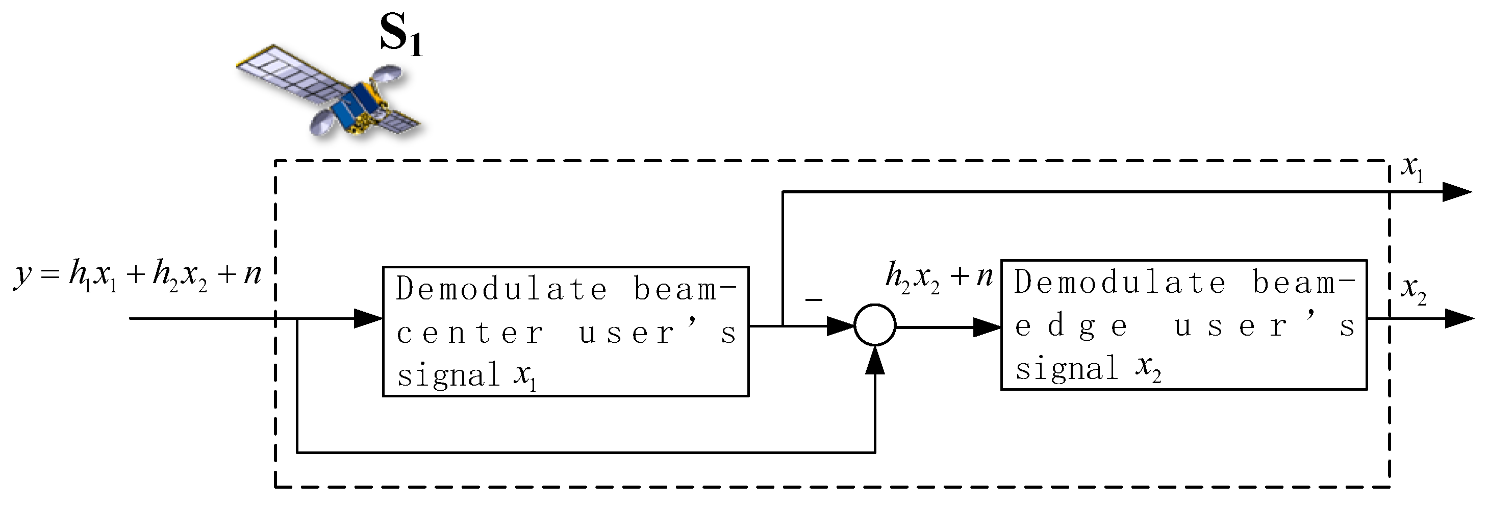
In downlink NOMA, which has been widely discussed, the weak user’s signal should be firstly decoded at the strong user side since the power allocated to the weak user’s signal is always high. However, as the signals of beam-center and beam-edge users may experience different channel attenuation in uplink SATCOM, the signal of beam-center user is considered to be demodulated first at the satellite, which is shown in Figure 2.
Provided a demodulation threshold T 1 , the outage probability of U 1 can be defined as P r 1 = P ( S I N R 1 < T 1 ) . Let β = P σ 2 . Then, we have the following theorem.
Theorem 1.
The outage probability of beam-center user in the uplink LEO NOMA is provided by
P r 1 = P ( S I N R 1 < T 1 ) = 1 κ 2 , l i = 1 n ω i F ( x i κ 2 , l ) ,
where F ( x ) = ε 1 , l k = 0 ( m 1 , l ) k ν 1 , l k ( k ! ) 2 κ 1 , l k + 1 t = 0 ( 1 ) t t ! ( k + 1 + t ) T 1 ( x K 2 α β + 1 ) K 1 ( 1 α ) β κ 1 , l k + 1 + t ε 2 , l 1 F 1 ( m 2 , l ; 1 ; ν 2 , l x ) . Here, K 1 = l 2 ( d l ) G 1 G l ( θ 1 ) and K 2 = l 2 ( d l ) G 2 G l ( θ 2 ) , x i and ω i denote the Gauss–Laguerre quadrature nodes and weights over [ 0 , + ] [25].
Proof. 
According to (4), the outage probability of U 1 can be calculated as
P r 1 = P ( S I N R 1 < T 1 ) = Pr ( | h 1 | 2 ( 1 α ) P | h 2 | 2 α P + σ 2 < T 1 ) = Pr ( | h 1 | 2 < T 1 ( | h 2 | 2 α P + σ 2 ) ( 1 α ) P ) = Pr ( | ρ 1 , l | 2 < T 1 ( | ρ 2 , l | 2 K 2 α β + 1 ) K 1 ( 1 α ) β ) .
Since Shadowed Rician channel model is assumed in this paper, (11) can be further expressed as
P r 1 = 0 0 T 1 ( | ρ 2 , l | 2 K 2 α β + 1 ) K 1 ( 1 α ) β f | ρ 1 , l | 2 ( x ) d x f | ρ 2 , l | 2 ( y ) d y = 0 ε 1 , l k = 0 ( m 1 , l ) k ν 1 , l k ( k ! ) 2 κ 1 , l k + 1 γ ( k + 1 , T 1 ( y K 2 α β + 1 ) K 1 ( 1 α ) β κ 1 , l ) f | ρ 2 , l | 2 ( y ) d y = 0 ε 1 , l k = 0 ( m 1 , l ) k ν 1 , l k ( k ! ) 2 κ 1 , l k + 1 γ ( k + 1 , T 1 ( y K 2 α β + 1 ) K 1 ( 1 α ) β κ 1 , l ) ε 2 , l e κ 2 , l y 1 F 1 ( m 2 , l ; 1 ; ν 2 , l y ) d y .
Motivated by Equation (8.354.1) in [24], Equation (12) can be further derived as
P r 1 = 0 ε 1 , l k = 0 ( m 1 , l ) k ν 1 , l k ( k ! ) 2 κ 1 , l k + 1 t = 0 ( 1 ) t t ! ( k + 1 + t ) T 1 ( y K 2 α β + 1 ) K 1 ( 1 α ) β κ 1 , l k + 1 + t ε 2 , l e κ 2 , l y 1 F 1 ( m 2 , l ; 1 ; ν 2 , l y ) d y = 0 e κ 2 , l y ε 1 , l k = 0 ( m 1 , l ) k ν 1 , l k ( k ! ) 2 κ 1 , l k + 1 t = 0 ( 1 ) t t ! ( k + 1 + t ) T 1 ( y K 2 α β + 1 ) K 1 ( 1 α ) β κ 1 , l k + 1 + t ε 2 , l 1 F 1 ( m 2 , l ; 1 ; ν 2 , l y ) F ( y ) d y = ( a ) 1 κ 2 , l i = 1 n ω i F ( x i κ 2 , l ) ,
where ( a ) follows Gauss–Laguerre quadrature.
The theorem is proved. □
To obtain the information of U 2 , the satellite should correctly decode both x 1 and x 2 . In this case, outage probability of U 2 happens when the satellite failed to demodulate x 1 or x 2 , i.e., P r 2 = P ( S I N R 1 < T 1 o r S N R 2 < T 2 ) . Then, we can derive the following theorem for the beam-edge user.
Theorem 2.
The outage probability of the beam-edge user can be calculated as
P r 2 = P ( S I N R 1 < T 1 o r S N R 2 < T 2 ) = ε 1 , l k = 0 ( m 1 , l ) k ν 1 , l k ( k ! ) 2 κ 1 , l k + 1 γ ( k + 1 , T 2 K 2 α β κ 1 , l ) + e T 2 κ 2 , l α β K 2 κ 2 , l i = 1 n ω i G ( x i κ 2 , l + T 2 α β K 2 ) ,
where G ( y ) = ε 1 , l k = 0 ( m 1 , l ) k ν 1 , l k ( k ! ) 2 κ 1 , l k + 1 γ ( k + 1 , T 1 ( y K 2 α β + 1 ) K 1 ( 1 α ) β κ 1 , l ) ε 2 , l 1 F 1 ( m 2 , l ; 1 ; ν 2 , l y ) . Also, x i and ω i denote the Gauss–Laguerre quadrature nodes and weights over [ 0 , + ] .
Proof. 
The definition of P r 2 can be further written as
P r 2 = P ( S I N R 1 < T 1 o r S N R 2 < T 2 ) = 1 P ( | h 1 | 2 ( 1 α ) P | h 2 | 2 α P + σ 2 T 1 , | h 2 | 2 α P σ 2 T 2 ) = 1 P ( | h 1 | 2 T 1 ( | h 2 | 2 α β + 1 ) ( 1 α ) β , | h 2 | 2 T 2 α β ) = 1 P ( | ρ 1 , l | 2 T 1 ( | ρ 2 , l | 2 K 2 α β + 1 ) K 1 ( 1 α ) β , | ρ 2 , l | 2 T 2 α β K 2 ) .
Following the distribution of Shadowed Rician, (15) can be calculated as
P r 2 = 1 T 2 α β K 2 T 1 ( y K 2 α β + 1 ) K 1 ( 1 α ) β f | ρ 1 , l | 2 ( x ) d x f | ρ 2 , l | 2 ( y ) d y = 1 T 2 α β K 2 ( 1 F | ρ 1 , l | 2 ( T 1 ( y K 2 α β + 1 ) K 1 ( 1 α ) β ) ) f | ρ 2 , l | 2 ( y ) d y = 1 T 2 α β K 2 f | ρ 2 , l | 2 ( y ) d y + T 2 α β K 2 F | ρ 1 , l | 2 ( T 1 ( y K 2 α β + 1 ) K 1 ( 1 α ) β ) f | ρ 2 , l | 2 ( y ) d y = F | ρ 1 , l | 2 ( T 2 α β K 2 ) + T 2 α β K 2 F | ρ 1 , l | 2 ( T 1 ( y K 2 α β + 1 ) K 1 ( 1 α ) β ) f | ρ 2 , l | 2 ( y ) d y = F | ρ 1 , l | 2 ( T 2 α β K 2 ) + T 2 α β K 2 e κ 2 , l y ε 1 , l k = 0 ( m 1 , l ) k ν 1 , l k ( k ! ) 2 κ 1 , l k + 1 γ ( k + 1 , T 1 ( y K 2 α β + 1 ) K 1 ( 1 α ) β κ 1 , l ) ε 2 , l 1 F 1 ( m 2 , l ; 1 ; ν 2 , l y ) G ( y ) d y = ( b ) ε 1 , l k = 0 ( m 1 , l ) k ν 1 , l k ( k ! ) 2 κ 1 , l k + 1 γ ( k + 1 , T 2 K 2 α β κ 1 , l ) + e T 2 κ 2 , l α β K 2 κ 2 , l i = 1 n ω i G ( x i κ 2 , l + T 2 α β K 2 ) ,
where ( b ) also follows Gauss–Laguerre quadrature.
The theorem is proved. □

3.2. Outage Probability of Cooperative OMA

When users move to the beam edge of the LEO satellite, GEO SATCOM network can be used as a complementary solution. In this scenario, the beam-edge user would be served by the GEO satellite with an independent channel. Then, the uplink of beam-center and beam-edge users is viewed as OMA, where the GEO and LEO satellites work cooperatively.
Since the uplink channels of the beam-center user and the beam-edge user are spectrally independent in cooperative OMA, the definitions of both outage probabilities can be expressed as P r 1 = P ( S N R 1 < T 0 ) and P r 2 = P ( S N R 2 < T 0 ) , respectively.
For U 1 , the outage probability can be further calculated as
P r 1 = P ( S N R 1 < T 0 ) = P ( | h 1 | 2 ( 1 α ) β < T 0 ) = P ( | ρ 1 , l | 2 < T 0 ( 1 α ) β K 1 ) = 0 T 0 ( 1 α ) β K 1 f | ρ 1 , l | 2 ( y ) d y = ε 1 , l k = 0 ( m 1 , l ) k ν 1 , l k ( k ! ) 2 κ 1 , l k + 1 γ ( k + 1 , T 0 ( 1 α ) β K 1 κ 1 , l ) .
According to (9), the outage probability of U 2 can be written as
P r 2 = P ( S N R 2 < T 0 ) = P ( | g 2 | 2 α β < T 0 ) = P ( | g 2 | 2 < T 0 α β ) = P ( | ρ 2 , g | 2 < T 0 l 2 ( d g ) G 2 G s α β ) = 0 T 0 l 2 ( d g ) G 2 G s α β f | ρ 2 , g | 2 ( x ) d x .
Let K 2 = l 2 ( d g ) G 2 G s . (18) becomes
P r 2 = 0 T 0 K 2 α β f | ρ 2 , g | 2 ( x ) d x = ε 2 , g k = 0 ( m 2 , g ) k ν 2 , g k ( k ! ) 2 κ 2 , g k + 1 γ ( k + 1 , T 0 K 2 α β κ 2 , g ) .

3.3. Performance with Ordered Channel Gain

Consider that the large-scale fading of beam-edge user is usually much worse than that of the beam-center user. We can derive the following assumption.
Assumption A1.
In LEO NOMA scenario, the uplink channel condition of the beam-center user is considered to be superior compared with that of the beam-edge user, i.e., | ρ 2 , l | 2 < | ρ 1 , l | 2 .
According to Assumption 1, the large-scale fading should be ordered first. The joint probability density function (pdf) of | ρ 1 , l | 2 and | ρ 2 , l | 2 can be expressed as [26]
p i j ( y , z ) = n ! ( i 1 ) ! ( j i 1 ) ! ( n j ) ! [ F ( y ) ] i 1 [ F ( z ) F ( y ) ] j i 1 [ 1 F ( z ) ] n j f ( y ) f ( z ) ,
where y < z . n = 2 denotes the number of users; i = 1 and j = 2 represent the beam-edge and beam-center users. Then, the joint pdf is provided by
p | ρ 2 , l | 2 , | ρ 1 , l | 2 ( y , z ) = 2 f | ρ 2 , l | 2 ( y ) f | ρ 1 , l | 2 ( z ) .
For the beam-center user, uplink outage satisfies | ρ 2 , l | 2 < | ρ 1 , l | 2 < T 1 ( | ρ 2 , l | 2 K 2 α β + 1 ) K 1 ( 1 α ) β after the channel ordering. Then, we have | ρ 2 , l | 2 < T 1 ( K 1 ( 1 α ) T 1 K 2 α ) β . Let χ = T 1 ( K 1 ( 1 α ) T 1 K 2 α ) β . (11) becomes
P r 1 = Pr ( | ρ 1 , l | 2 < T 1 ( | ρ 2 , l | 2 K 2 α β + 1 ) K 1 ( 1 α ) β ) = 2 0 χ y T 1 ( y K 2 α β + 1 ) K 1 ( 1 α ) β f | ρ 1 , l | 2 ( x ) d x f | ρ 2 , l | 2 ( y ) d y = 2 0 χ ε 1 , l k = 0 ( m 1 , l ) k ν 1 , l k ( k ! ) 2 κ 1 , l k + 1 γ ( k + 1 , T 1 ( y K 2 α β + 1 ) K 1 ( 1 α ) β κ 1 , l ) ε 1 , l k = 0 ( m 1 , l ) k ν 1 , l k ( k ! ) 2 κ 1 , l k + 1 γ ( k + 1 , y κ 1 , l ) f | ρ 2 , l | 2 ( y ) d y = 2 0 χ e κ 2 , l y ε 1 , l k = 0 ( m 1 , l ) k ν 1 , l k ( k ! ) 2 κ 1 , l k + 1 γ ( k + 1 , T 1 ( y K 2 α β + 1 ) K 1 ( 1 α ) β κ 1 , l ) ε 1 , l k = 0 ( m 1 , l ) k ν 1 , l k ( k ! ) 2 κ 1 , l k + 1 γ ( k + 1 , y κ 1 , l ) ε 2 , l 1 F 1 ( m 2 , l ; 1 ; ν 2 , l y ) M ( y ) d y = ( c ) χ π N n = 1 N 1 x n 2 M ( y n , 1 ) ,
where x n = cos ( 2 n 1 2 N π ) and y n , 1 = ( x n + 1 ) χ 2 . ( c ) follows Gauss–Chebyshev approximation [27].
The outage probability of the beam-edge user can be further expressed as P r 2 = P ( | h 1 | 2 < T 1 ( | h 2 | 2 α β + 1 ) ( 1 α ) β ) P r 1 + P ( | h 1 | 2 T 1 ( | h 2 | 2 α β + 1 ) ( 1 α ) β , | h 2 | 2 < T 2 α β ) S 1 . Since P r 1 has been derived in (22), we will focus on the deduction of S 1 . Similarly, S 1 can be rewritten as P ( | ρ 1 , l | 2 T 1 K 2 | ρ 2 , l | 2 α β + T 1 ( 1 α ) β K 1 , | ρ 2 , l | 2 < T 2 α β K 2 ) . As | ρ 1 , l | 2 > | ρ 2 , l | 2 is assumed in this section, we have | ρ 1 , l | 2 max { T 1 K 2 | ρ 2 , l | 2 α β + T 1 ( 1 α ) β K 1 , | ρ 2 , l | 2 } . Letting ζ = max { T 1 K 2 | ρ 2 , l | 2 α β + T 1 ( 1 α ) β K 1 , | ρ 2 , l | 2 } , S 1 can be calculated as
S 1 = P ( | ρ 1 , l | 2 ζ , | ρ 2 , l | 2 < T 2 α β K 2 ) = 2 0 T 2 α β K 2 f | ρ 2 , l | 2 ( y ) d y ζ f | ρ 1 , l | 2 ( x ) d x = 2 0 T 2 α β K 2 1 ε 1 , l k = 0 ( m 1 , l ) k ν 1 , l k ( k ! ) 2 κ 1 , l k + 1 γ ( k + 1 , ζ κ 1 , l ) f | ρ 2 , l | 2 ( y ) d y = 2 ε 2 , l k = 0 ( m 2 , l ) k ν 2 , l k ( k ! ) 2 κ 2 , l k + 1 γ ( k + 1 , T 2 α β K 2 κ 2 , l ) 2 0 T 2 α β K 2 e κ 2 , l y ε 2 , l 1 F 1 ( m 2 ; 1 ; ν 2 , l y ) ε 1 , l k = 0 ( m 1 , l ) k ν 1 , l k ( k ! ) 2 κ 1 , l k + 1 γ ( k + 1 , ζ κ 1 , l ) Z ( y ) d y = 2 ε 2 , l k = 0 ( m 2 , l ) k ν 2 , l k ( k ! ) 2 κ 2 , l k + 1 γ ( k + 1 , T 2 α β K 2 κ 2 , l ) T 2 π α β K 2 N n = 1 N 1 x n 2 Z ( y n , 2 ) ,
where x n = cos ( 2 n 1 2 N π ) and y n , 2 = ( x n + 1 ) T 2 2 α β K 2 . Consequently, we obtain the expression of P r 2 = P r 1 + S 1 .

4. Diversity Order Analysis

To provide more insights regarding the outage probability with ordered channel, we provide the diversity order as an asymptotic reliability metric [28,29]. In the context, the diversity order can be defined as
D = lim β log ( P r ( β ) ) log β ,
where P r ( β ) denotes the asymptotic outage probability. Next, we analyze the asymptotic outage probability for U 1 and U 2 .
Corollary 1.
The asymptotic outage probability of U 1 in high-SNR region is provided by
P r 1 ( β ) = χ π N n = 1 N 1 x n 2 ε 1 , l k = 0 ( m 1 , l ) k ν 1 , l k ( k ! ) 2 κ 1 , l k + 1 ( k + 1 ) ( T 1 ( y n , 1 K 2 α β + 1 ) K 1 ( 1 α ) β κ 1 , l ) k + 1 ε 1 , l k = 0 ( m 1 , l ) k ν 1 , l k ( k ! ) 2 κ 1 , l k + 1 ( y n , 1 κ 1 , l ) k + 1 k + 1 × ε 2 , l 1 F 1 ( m 2 , l ; 1 ; ν 2 , l y n , 1 ) .
Proof. 
In (22), we have γ ( k + 1 , T 1 ( y n , 1 K 2 α β + 1 ) K 1 ( 1 α ) β κ 1 , l ) = n = 0 ( 1 ) n ( T 1 ( y n , 1 K 2 α β + 1 ) K 1 ( 1 α ) β κ 1 , l ) k + 1 + n n ! ( k + 1 + n ) . When β , y n , 1 = ( x n + 1 ) χ 2 0 . Thus, T 1 ( y n , 1 K 2 α β + 1 ) K 1 ( 1 α ) β κ 1 , l 0 still holds in high-SNR region. In this case, γ ( k + 1 , T 1 ( y n , 1 K 2 α β + 1 ) K 1 ( 1 α ) β κ 1 , l ) T 1 ( y n , 1 K 2 α β + 1 ) K 1 ( 1 α ) β κ 1 , l k + 1 k + 1 . Consequently, the asymptotic outage probability of U 1 can be derived as (25).
The corollary is proved. □
Remark 1.
Substituting (25) into (24), we can derive the diversity order of the beam-center user as 2.
Following the similar procedure, we have S 1 ( β ) = 2 ε 2 , l k = 0 ( m 2 , l ) k ν 2 , l k ( k ! ) 2 κ 2 , l k + 1 ( k + 1 ) T 2 α β K 2 κ 2 , l k + 1 T 2 π α β K 2 N n = 1 N 1 x n 2 ε 2 , l 1 F 1 ( m 2 ; 1 ; ν 2 , l y n , 2 ) ε 1 , l k = 0 ( m 1 , l ) k ν 1 , l k ( k ! ) 2 κ 1 , l k + 1 ( k + 1 ) ( ζ κ 1 , l ) k + 1 . Then, the asymptotic outage probability of U 2 is derived in the following corollary.
Corollary 2.
The asymptotic outage probability of U 2 in high-SNR region is provided by
P r 2 ( β ) = P r 1 ( β ) + S 1 ( β ) = χ π N n = 1 N 1 x n 2 ε 1 , l k = 0 ( m 1 , l ) k ν 1 , l k ( k ! ) 2 κ 1 , l k + 1 ( k + 1 ) ( T 1 ( y n , 1 K 2 α β + 1 ) K 1 ( 1 α ) β κ 1 , l ) k + 1 ε 1 , l k = 0 ( m 1 , l ) k ν 1 , l k ( k ! ) 2 κ 1 , l k + 1 ( y n , 1 κ 1 , l ) k + 1 k + 1 × ε 2 , l 1 F 1 ( m 2 , l ; 1 ; ν 2 , l y n , 1 ) + 2 ε 2 , l k = 0 ( m 2 , l ) k ν 2 , l k ( k ! ) 2 κ 2 , l k + 1 ( k + 1 ) T 2 α β K 2 κ 2 , l k + 1 T 2 π α β K 2 N n = 1 N 1 x n 2 ε 2 , l 1 F 1 ( m 2 ; 1 ; ν 2 , l y n , 2 ) ε 1 , l k = 0 ( m 1 , l ) k ν 1 , l k ( k ! ) 2 κ 1 , l k + 1 ( k + 1 ) ( ζ κ 1 , l ) k + 1 .
Remark 2.
Substituting (26) into (24), we can derive the diversity order of the beam-edge user as 1.

5. Simulation Results

In this section, we provide simulation results of LEO NOMA and cooperative OMA methods. Then, the transmission reliability is further discussed. Throughout the simulation, system and Shadowed Rician fading channel parameters are provided in Table 1 and Table 2 [30]. Let R 1 = log ( 1 + T 1 ) and R 2 = log ( 1 + T 2 ) denote the achievable rate of U 1 and U 2 at thresholds T 1 and T 2 in the LEO NOMA method, respectively. For comparable reasons, we set R 0 = R 1 + R 2 = log ( 1 + T 0 ) as the achievable rate for both U 1 and U 2 in a cooperative OMA scheme.

5.1. Outage Probability Without Channel Ordering

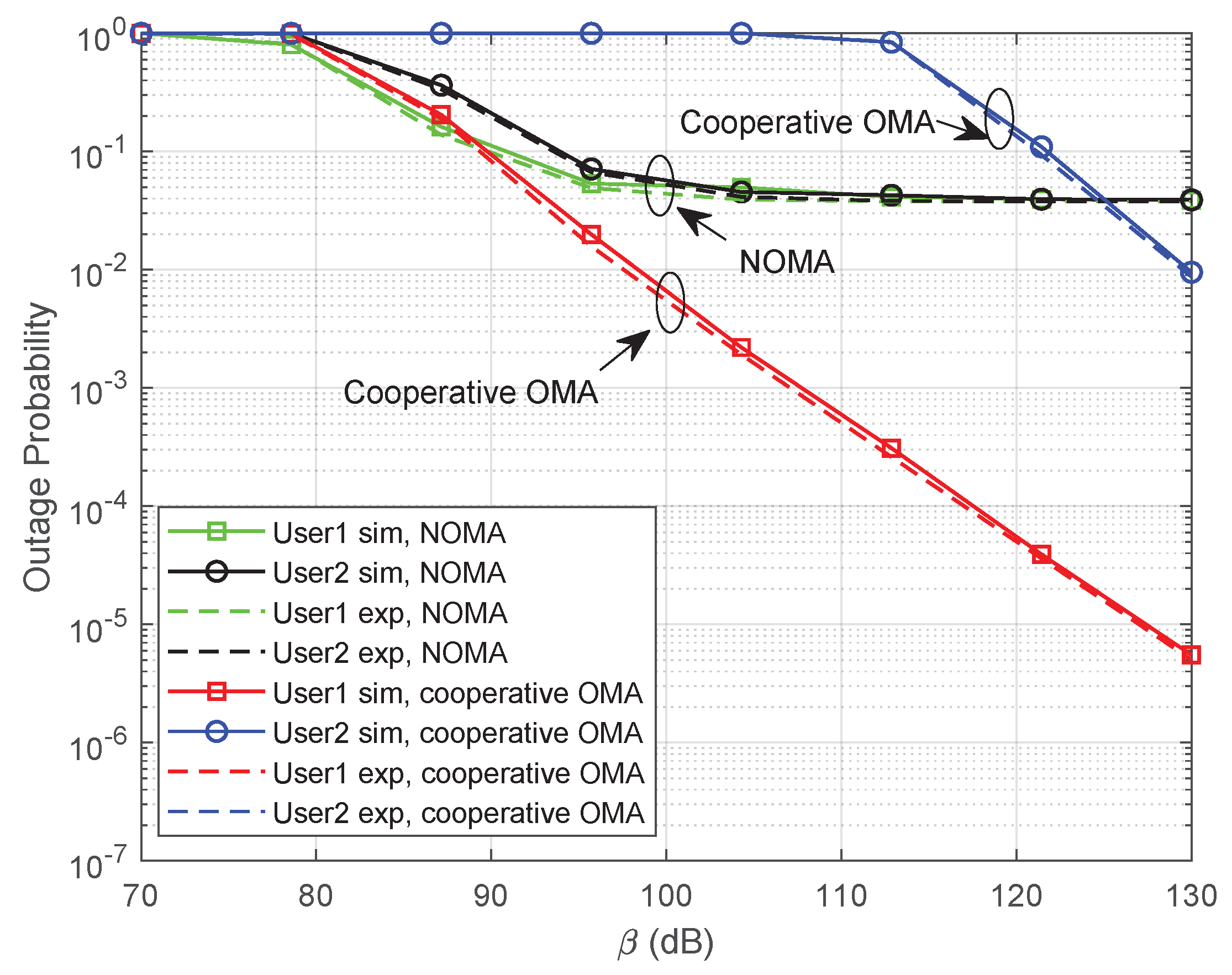
In this subsection, we focus on the outage probability performance without Assumption 1. We first consider the FHS channel condition. The values of achievable rate for U 1 and U 2 are set as R 1 = 0.4 bps and R 2 = 0.3 bps. The power factor for U 2 is assumed as α = 0.2 . Figure 3 illustrates the results of outage probability with variable β . It is clearly shown that the curves of analytical expressions perfectly match with those of numerical simulations, which validates the correctness of Theorems 1 and 2. From Figure 3, we can deeply find out that the NOMA method outperforms the cooperative OMA in the low-SNR region; even U 2 could not be guaranteed in the OMA scheme. It can be explained by the fact that interference from x 2 exists when decoding the signal of U 1 in uplink NOMA. In this case, the outage probability of U 1 could not be improved; even SNR grows to high values. Since x 1 should also be demodulated when decoding the signal of U 2 , the outage probability error floor could not be avoided for the curve of U 2 . In addition, by substituting (10) and (14) into (24), respectively, the diversity order can be found as zero. Thus, the outage probability could not be improved even in the high-SNR region. However, we can choose to apply cooperative OMA when SNR is relatively high.
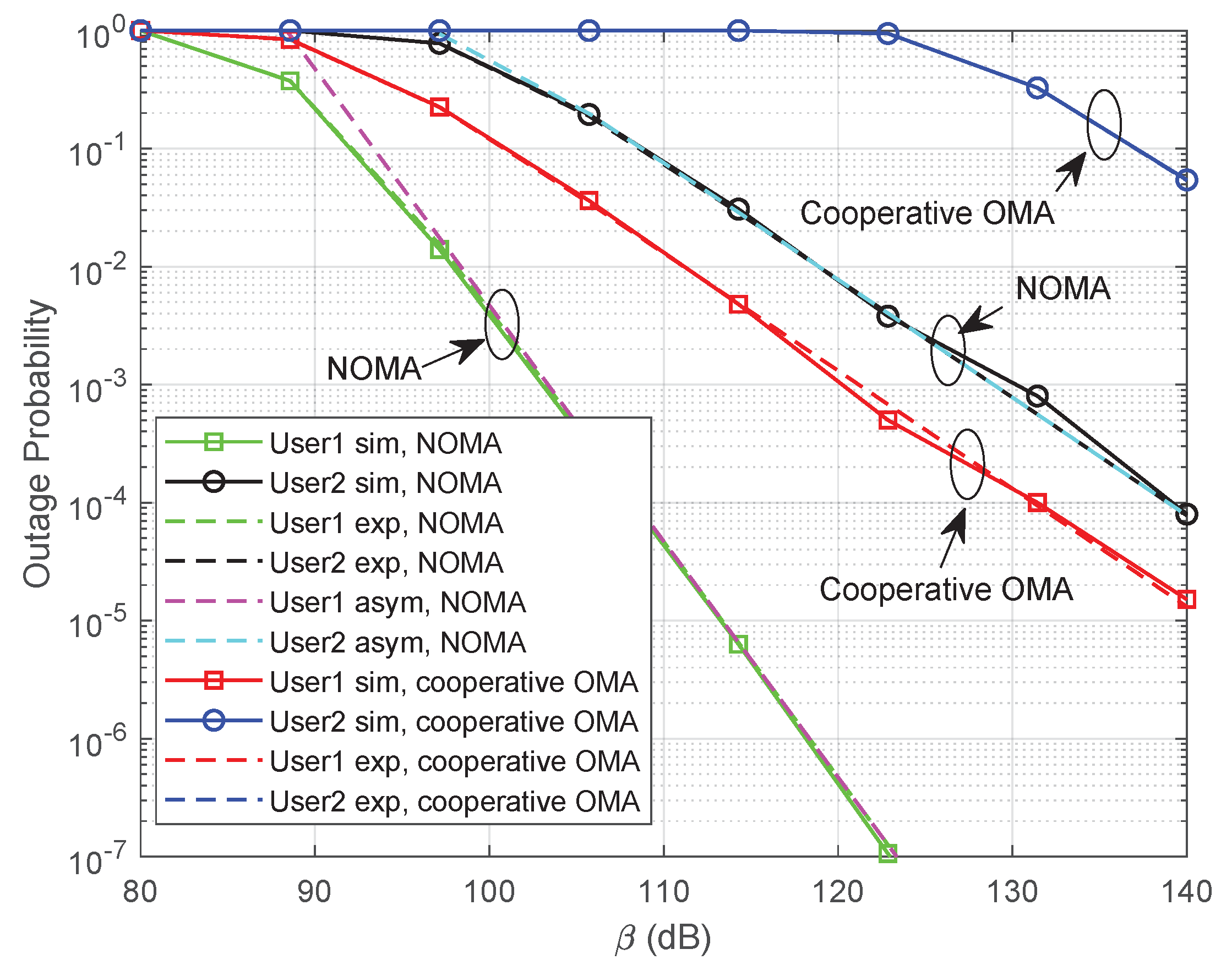
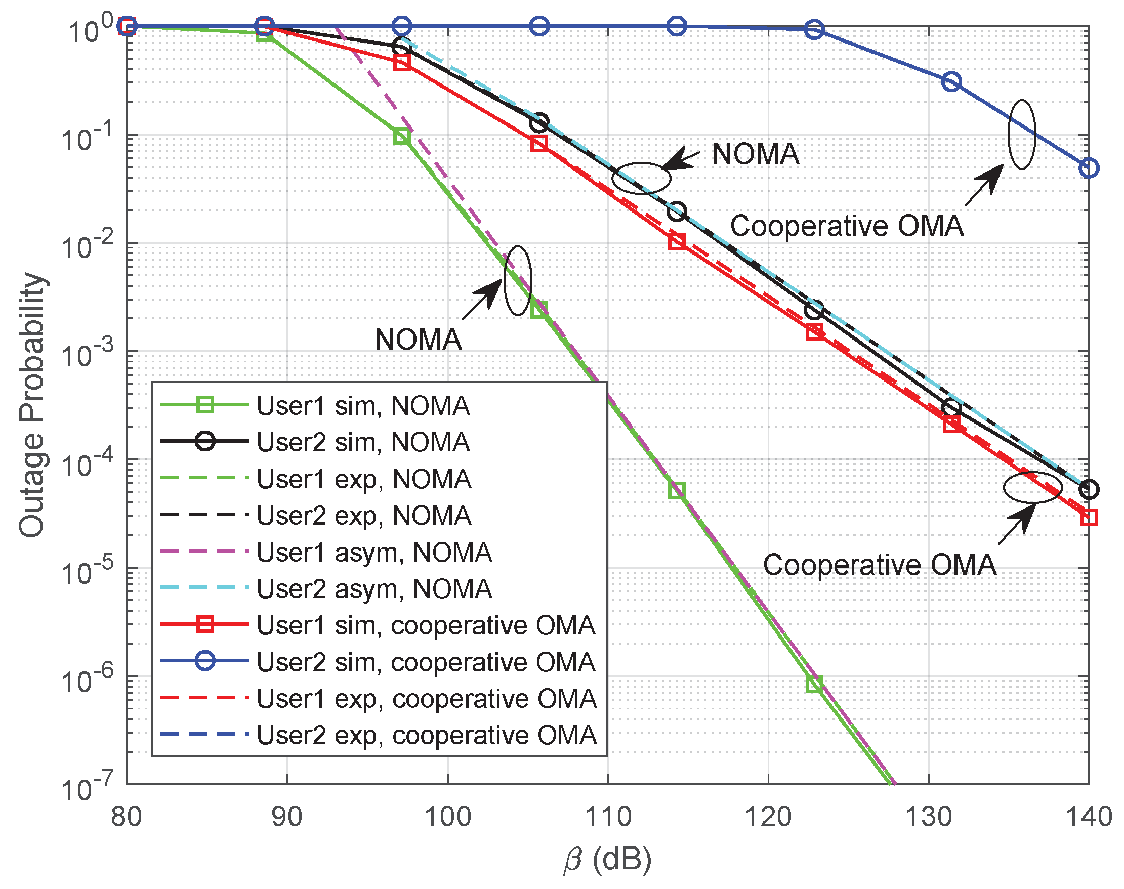
Figure 4 shows the result in an AS transmission environment. It is noteworthy that the outage probability can be greatly improved since the channel condition is better compared with FHS. Again, we can derive the conclusion that the NOMA scheme performs better in the low-SNR region and is more friendly for beam-edge users. This is because the uplink signals of the beam-edge user experience more transmission path loss when the beam-edge user connects the GEO satellite in a cooperative OMA scheme. When we allocate more power resources to U 2 , cooperative OMA is more promising compared with NOMA, which can be clearly determined in Figure 5.
From Figure 5, it can be clearly noticed that the outage probability performance of U 1 in both methods degrades since more transmission power has been allocated to the beam-edge user. Fortunately, the performance of U 2 can be improved by taking more power resources, which may help the cooperative OMA to be practicable in the low-SNR region.

5.2. Outage Probability With Ordered Channel Gain

In this subsection, we provide simulation results under the condition of Assumption 1. Figure 6 illustrates the results in an FHS environment with α = 0.2 . It can be clearly noticed that NOMA can provide a huge performance gain compared with cooperative OMA when we consider channel ordering. This is because | ρ 2 , l | 2 < | ρ 1 , l | 2 is assumed in channel ordering circumstances. In this case, | h 2 | 2 < | h 1 | 2 always holds when calculating the SINR. Then, the interference can be relatively relieved while the diversity order of U 1 and U 2 increases. The result can also be confirmed from Remarks 1 and 2. In real uplink transmission scenarios, the channel ordering exists since the signal of a beam-edge user often experiences significant path loss. Further, we can find that the asymptotic outage probability approximates the exact outage probability curves well, which validates the correctness of Corollaries 1 and 2.
By setting a relatively high achievable rate for U 1 and U 2 , we derive the outage probability in Figure 7, where R 1 = 0.7 bps and R 2 = 0.4 bps. The power factor for U 2 is assumed to be α = 0.4 . It is noteworthy that the performance of U 1 has degraded since the system provides less power for U 1 . Another reason is that we set a higher achievable rate for U 1 . This will cause outage probability performance degradation. Again, NOMA outperforms cooperative OMA when the channel is ordered.

6. Conclusions

In this paper, we studied the uplink outage probability for LEO NOMA and cooperative OMA, where both GEO and LEO satellites are considered. Realizing that there exists much uplink beam gain difference between beam-center and beam-edge users, we can allocate these two users in one resource block with the help of NOMA. To deeply analyze the performance of outage probability, we provided analytical expressions for beam-edge and beam-center users under the circumstances of LEO NOMA and GEO–LEO cooperative OMA. Considering the channel fading difference in the beam-center and beam-edge users, the outage probability is further discussed under the condition of channel ordering. Moreover, the asymptotic outage probability is analyzed and the diversity order is also derived. The simulation results show that NOMA outperforms cooperative OMA in the low-SNR region. Since NOMA will provide interference in the process of demodulation, the diversity order would be zero, which may cause the outage probability to attain an error floor in the high-SNR region. When the uplink channel is assumed to be ordered, the interference would be relieved, which can be judged from Remarks 1 and 2. In this case, NOMA is able to provide a promising outage probability compared with cooperative OMA. Note that high reliable transmission methods for a multi-user scenario would be discussed in our future work. One possible solution for multi-user uplink NOMA is that we separate users as beam-center and beam-edge sets. Then, we select one user from each set as a user pair. The two users in one pair are allocated in one resource block, while different pairs take separate timeslots or carrier resource blocks. This can be viewed as TDMA–NOMA or FDMA–NOMA. Following this, user paring would be one of the key technologies that should be solved.

Author Contributions

Conceptualization, G.L. and T.L.; Methodology, T.L. and G.L.; Validation, T.L. and X.Y.; Writing—Original Draft Preparation, T.L., X.Y., T.H. and B.D.; Writing—Review and Editing, T.L., X.Y., T.H. and B.D. All authors have read and agreed to the published version of the manuscript.

Funding

This work was supported by the National Natural Science Foundation of China under Grant Nos. 62201533 and 62201283.

Data Availability Statement

Not applicable.

Conflicts of Interest

The authors declare no conflict of interest.

Appendix A. Symbols and Acronyms

The symbols and acronyms used in this paper are summarized below.
Table A1. A list of symbols and acronyms.
6GSixth Generation
ASAverage Shadowing
BERBit Error Rate
BSBase Station
CSCGCircularly Symmetric Complex Gaussian
FDMAFrequency Division Multiple Access
FHSFrequent Heavy Shadowing
GEOGeostationary Earth Orbit
ILSInfrequent Light Shadowing
IPInternet Protocol
LEOLow Earth Orbit
LoSLine of Sight
MbpsMegabits per Second
MEOMedium Earth Orbit
NOMANon-Orthogonal Multiple Access
NTNNon-Terrestrial Network
OMAOrthogonal Multiple Access
pdfProbability Density Function
SATCOMSatellite Communication
SICSuccessive Interference Cancellation
SINRSignal-to-Interference-Noise Ratio
SNRSignal-to-Noise Ratio
TDMATime Division Multiple Access

References

  1. Al-Hraishawi, H.; Chougrani, H.; Kisseleff, S.; Lagunas, E.; Chatzinotas, S. A Survey on nongeostationary satellite systems: The communication perspective. IEEE Commun. Surv. Tutor. 2023, 25, 101–132. [Google Scholar] [CrossRef]
  2. 3GPP. Study on Integration of Satellite Components in the 5G Architecture: TR 23.700-28 v0.3.0. 2022. Available online: https://portal.3gpp.org/desktopmodules/Specifications/SpecificationDetails.aspx?specificationId=4012 (accessed on 1 July 2023).
  3. Zhang, X.; Zhu, L.; Li, T.; Xia, Y.; Zhuang, W. Multiple-User transmission in space information networks: Architecture and key techniques. IEEE Wirel. Commun. 2019, 26, 17–23. [Google Scholar] [CrossRef]
  4. Sun, C. Research status and problems for space-based transmission network and space-ground integrated information network. Radio Eng. 2017, 47, 1–6. [Google Scholar]
  5. Chen, S.; Sun, S.; Kang, S. System integration of terrestrial mobile communication and satellite communication-the trends, challenges and key technologies in B5G and 6G. China Commun. 2020, 17, 156–171. [Google Scholar] [CrossRef]
  6. Neinavaie, M.; Khalife, J.; Kassas, Z.M. Acquisition, doppler tracking, and positioning with starlink LEO satellites: First results. IEEE Trans. Aerosp. Electron. Syst. 2022, 58, 2606–2610. [Google Scholar] [CrossRef]
  7. Ren, S.; Yang, X.; Wang, R.; Liu, S.; Sun, X. The interaction between the LEO satellite constellation and the space debris environment. Appl. Sci. 2021, 11, 9490. [Google Scholar] [CrossRef]
  8. Lyu, X.; Hristov, S.; Gashinova, M.; Stove, A.; Cherniakov, M. Ambiguity function analysis of the Inmarsat I-4 and Iridium signals. In Proceedings of the International Conference on Radar Systems (Radar 2017), Belfast, Northern Ireland, 23–26 October 2017. [Google Scholar]
  9. Mota, S.; Rocha, A.; Cupido, L.; Oliveira, M.; Costa, J. Challenges and achievements setting up a propagation campaign with MEO satellites. In Proceedings of the 17th European Conference on Antennas and Propagation (EuCAP), Florence, Italy, 26–31 March 2023. [Google Scholar]
  10. Kassas, Z.M.; Kozhaya, S.; Kanj, H.; Saroufim, J.; Hayek, S.W.; Neinavaie, M.; Khairallah, N.; Khalife, J. Navigation with multi-constellation LEO satellite signals of opportunity: Starlink, OneWeb, Orbcomm, and Iridium. In Proceedings of the 2023 IEEE/ION Position, Location and Navigation Symposium (PLANS), Monterey, CA, USA, 24–27 April 2023. [Google Scholar]
  11. Liang, Y.C.; Tan, J.; Jia, H.; Zhang, J.; Zhao, L. Realizing intelligent spectrum management for integrated satellite and terrestrial networks. J. Commun. Inf. Netw. 2021, 6, 32–43. [Google Scholar] [CrossRef]
  12. Yan, X.; Xiao, H.; An, K.; Zheng, G.; Tao, W. Hybrid satellite terrestrial relay networks with cooperative non-orthogonal multiple access. IEEE Commun. Lett. 2018, 22, 978–981. [Google Scholar] [CrossRef] [Green Version]
  13. Zhu, X.; Jiang, C.; Yin, L.; Kuang, L.; Ge, N.; Lu, J. Non-orthogonal multiple access based integrated terrestrial-satellite networks. IEEE J. Sel. Areas Commun. 2017, 35, 2253–2267. [Google Scholar] [CrossRef]
  14. Elhalawany, B.M.; Gamal, C.; Elsayed, A.; Elsherbini, M.M.; Fouda, M.M.; Ali, N. Outage analysis of coordinated NOMA transmission for LEO satellite constellations. IEEE Open J. Commun. Soc. 2022, 3, 2195–2202. [Google Scholar] [CrossRef]
  15. Li, T.; Hao, X.; Yue, X. A power domain multiplexing based co-carrier transmission method in hybrid satellite communication networks. IEEE Access 2020, 8, 120036–120043. [Google Scholar] [CrossRef]
  16. Li, T.; Hao, X.; Yue, X. A spectrum-saving transmission method in multi-antenna satellite communication star networks: Sharing the frequency with terminals. Entropy 2023, 25, 113. [Google Scholar] [CrossRef]
  17. Tegos, S.A.; Diamantoulakis, P.D.; Xia, J.; Fan, L.; Karagiannidis, G.K. Outage performance of uplink NOMA in land mobile satellite communications. IEEE Wirel. Commun. Lett. 2020, 9, 1710–1714. [Google Scholar] [CrossRef]
  18. Yan, X.; Xiao, H.; An, K.; Zheng, G.; Chatzinotas, S. Ergodic capacity of NOMA-based uplink satellite networks with randomly deployed users. IEEE Syst. J. 2020, 14, 3343–3350. [Google Scholar] [CrossRef]
  19. Lee, J.H.; Joo, J.S.; Kim, P.; Ryu, J.-G. Random beam-based non-orthogonal multiple access for massive MIMO low earth orbit satellite networks. IEEE Access 2023. early access. [Google Scholar] [CrossRef]
  20. Ge, R.; Cheng, J.; An, K.; Zheng, G. Non-orthogonal multiple access enabled two-layer GEO/LEO satellite network. In Proceedings of the 29th European Signal Processing Conference (EUSIPCO), Dublin, Ireland, 23–27 August 2021; pp. 890–894. [Google Scholar]
  21. Ge, R.; Bian, D.; Cheng, J.; An, K.; Hu, J.; Li, G. Joint user pairing and power allocation for NOMA-Based GEO and LEO satellite network. IEEE Access 2021, 9, 93255–93266. [Google Scholar] [CrossRef]
  22. Liu, R.; Guo, K.; An, K.; Zhou, F.; Wu, Y.; Huang, Y.; Zheng, G. Resource allocation for NOMA-enabled cognitive satellite-UAV-terrestrial networks with imperfect CSI. IEEE Trans. Cogn. Commun. Netw. 2023. early access. [Google Scholar] [CrossRef]
  23. Yan, X.; Xiao, H.; Wang, C.; An, K. Outage performance of NOMA-based hybrid satellite-terrestrial relay networks. IEEE Wirel. Commun. Lett. 2018, 7, 538–541. [Google Scholar] [CrossRef]
  24. Gradshteyn, I.S.; Ryzhik, I.M. Table of Integrals, Series and Products, 7th ed.; Academic Press: New York, NY, USA, 2007; pp. 1005–1006. [Google Scholar]
  25. Hildebrand, F.B. Introduction to Numerical Analysis, 2nd ed.; Dover publications: New York, NY, USA, 1987; pp. 392–393. [Google Scholar]
  26. David, H.A.; Nagaraja, H.N. Order Statistics, 3rd ed.; Wiley: Hoboken, NJ, USA, 2003. [Google Scholar]
  27. Abramowitz, M.; Stegun, I.A. Handbook of Mathematical Functions with Formulas, Graphs, and Mathematical Tables; American Journal of Physics: Washington, DC, USA, 1988. [Google Scholar]
  28. Ding, Z.; Yang, Z.; Fan, P.; Poor, H.V. On the performance of non-orthogonal multiple access in 5G systems with randomly deployed users. IEEE Signal Process. Lett. 2014, 21, 1501–1505. [Google Scholar] [CrossRef] [Green Version]
  29. Ashraf, S.; Ahmed, T.; Aslam, Z.; Muhammad, D.; Yahya, A.; Shuaeeb, M. Depuration based efficient coverage mechanism for wireless sensor network. J. Electr. Comput. Eng. Innov. 2020, 8, 145–160. [Google Scholar]
  30. Abdi, A.; Lau, W.C.; Alouini, M.-S.; Kaveh, M. A new simple model for landmobile satellite channels: First- and second-order statistics. IEEE Trans. Wirel. Commun. 2003, 2, 519–528. [Google Scholar] [CrossRef] [Green Version]
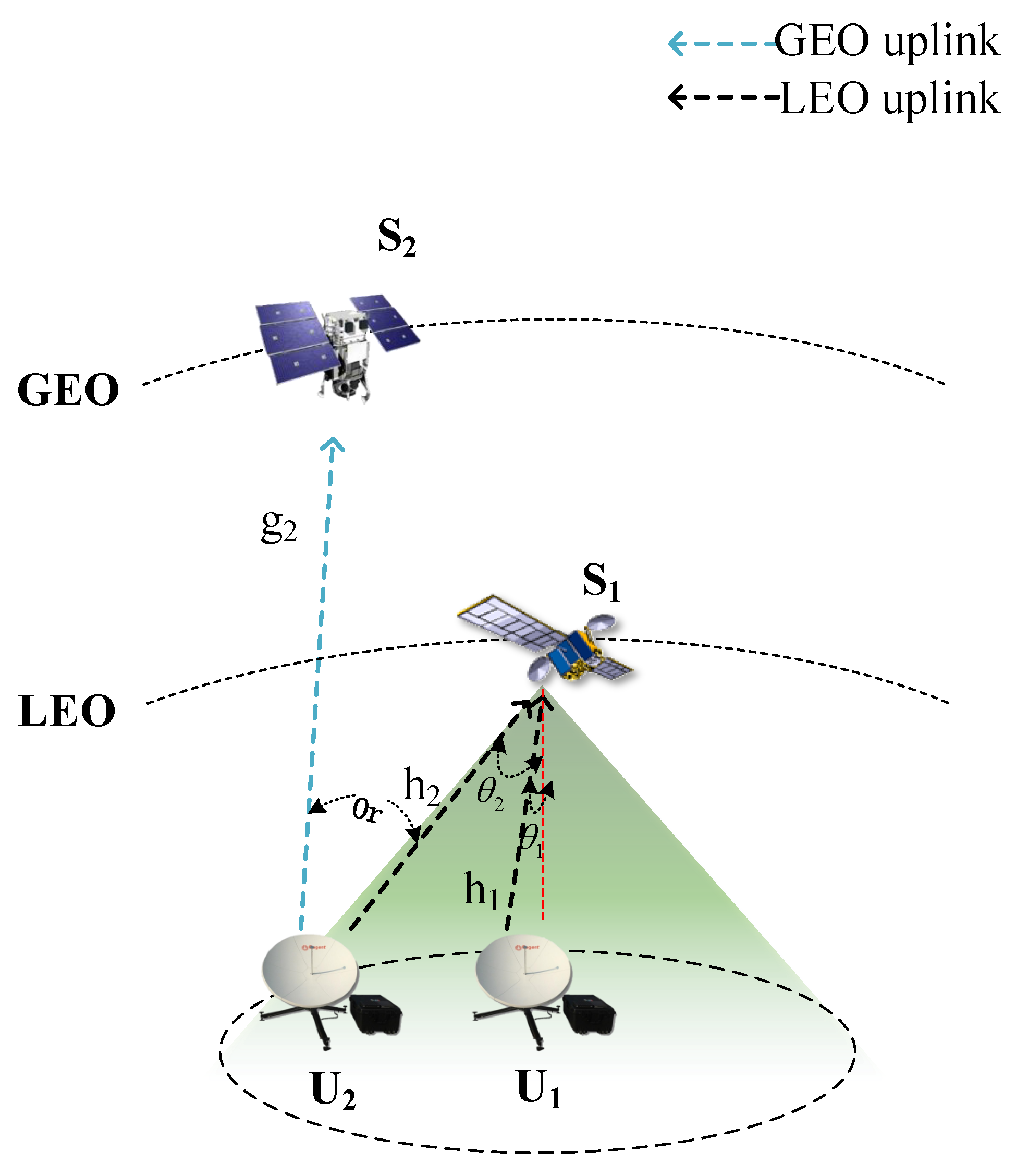
Figure 1. The GEO–LEO heterogeneous SATCOM network.
Applsci 13 08611 g001
Figure 2. The receiver structure of the satellite.
Applsci 13 08611 g002
Figure 3. Outage probability without channel ordering in FHS when α = 0.2 .
Applsci 13 08611 g003
Figure 4. Outage probability without channel ordering in AS when α = 0.2 .
Applsci 13 08611 g004
Figure 5. Outage probability without channel ordering in AS when α = 0.4 .
Applsci 13 08611 g005
Figure 6. Outage probability with channel ordering in FHS when α = 0.2 .
Applsci 13 08611 g006
Figure 7. Outage probability with channel ordering in FHS when α = 0.4 .
Applsci 13 08611 g007
Table 1. System parameters.
System ParameterValue
Orbit height of GEO satellite d g 36,000 km
Orbit height of LEO satellite d l 700 km
Carrier frequency28 GHz
Angle of 3 dB beam width at the LEO satellite θ 3 d B 2 . 5
Beam gain of the GEO receive antenna G s 54 dB
Normal-direction beam gain of LEO receive antenna G l 50 dB
Transmit beam gain of user terminals G i 45 dB
Table 2. Shadowed Rician fading channel parameters.
Shadowingbm Ω
Frequent heavy shadowing (FHS) 0.063 0.739 8.97 × 10 4
Average shadowing (AS) 0.126 10.1 0.835
Infrequent light shadowing (ILS) 0.158 19.4 1.29
Disclaimer/Publisher’s Note: The statements, opinions and data contained in all publications are solely those of the individual author(s) and contributor(s) and not of MDPI and/or the editor(s). MDPI and/or the editor(s) disclaim responsibility for any injury to people or property resulting from any ideas, methods, instructions or products referred to in the content.