Abstract
Considering the factors affecting the surrounding rock stability of gob-side entry retaining, the applicability of a large-diameter, concrete-filled steel tube roadside support body in a top-coal caving fully mechanized face is discussed, and a new approach to gob-side entry retaining is proposed in this study. The mechanical model of the surrounding rock structure of gob-side entry retaining in a top-coal caving fully mechanized face was established, the critical state of column–roof contact shear slip instability was clarified through Prandtl foundation failure theory, and the deformation mechanism of the surrounding rock of the retained roadway was analyzed through numerical simulation. The results indicated that the range of the tensile stress zone and extreme tensile stress of the roof between columns are closely related to the spacing of columns, which is the key factor influencing the deformation of the retained roadway. In addition, besides uncontrollable factors, the stability of the contact interface between the roof and columns is directly related to the area of the contact interface between the concrete-filled steel tubes and the roof, and the size of the critical contact area is directly related to the properties of top-coal mass. Finally, a field test was carried out in 91–101 working panels in the Wang-Zhuang Coal Mine; the maximum convergence of the roof and floor was 510 mm, and the area of the retained roadway section reached 12.9 m2, which is within a reasonable range.
1. Introduction
To reduce the amount of roadway excavation and improve the resource recovery rate [1] in recent decades, a pillarless longwall mining method called gob-side entry retaining (GER) has been studied and applied under different geological conditions in China [2]. Gob-side entry retaining technology not only reduces the waste of coal resources, but also makes the ventilation form with a “Y” layout, which can eliminate the risk of gas accumulation in the upper T-junction of the longwall [3]. At present, some types of gob-side entry retaining technology have been successfully applied in coal mines with a shallow buried depth, thin coal seams, and simple roof structures [4,5]. With the average mining depth of coal seams increasing, geological conditions are more complex, causing too many difficulties in the application of gob-side entry retaining under the condition of a large buried depth coal seam [6]. In this case, He M.C, etc. [7,8,9], proposed the means of gob-side entry retaining by using directional blasting to cut off the overhanging roof on the side of the gob and set large deformation constant resistance anchor cables in the roof of the roadway to reinforce the roof, make the severed, overhanging roof fall down, and form a roadway subsequently. This technology opens up new ideas and directions for pillarless mining in large-depth coal seams and achieves a good application effect in Yu-Lin mining areas in northern Shaanxi province [10]. The application effect of ‘self-forming roadway by roof cutting’ is good in thin coal seams and medium–thick coal seams with a thickness of less than 4.5 m, and most studies are also mainly focused on the application of ‘self-forming roadway by roof cutting’ in the conditions of thin coal seams and medium–thick coal seams [11]. However, for coal seam thicknesses greater than 4.5 m, due to the complex spatial relationship between the hydraulic supports in front of the working longwall, the top-coal mass, and the overlying rock strata, there is a great risk of hydraulic supports being crushed during the process of top-coal falling after the pre-splitting blasting cuts off the main roof [12]. Moreover, the problems of residual coal and gas accumulation pose a great safety risk through use of delayed blasting cutting roof. Therefore, it is difficult to realize a ‘self-forming roadway by roof cutting’ under the condition of top-coal caving; the applicability of the ‘self-forming roadway by roof cutting’ is not good in thick coal seams with top-coal caving; thus, gob-side entry retaining with side support still is an effective safety method in thick coal seams of fully mechanized working longwall [13].
Past research has shown that the deformation of the immediate roof, side wall, and immediate floor of the gob-side retained roadway are closely related [14]. The deformation of the immediate roof directly above the roadside support body determines the rotation of the main roof; excessive rotary deformation of the roof directly above the roadside support body will cause a series of chain reactions, such as failure and bulge of the solid coal wall, separation and breakage of the roof, the anchor cable sheared off, etc. Moreover, since the conversion of unloading–supporting determines a certain given deformation of the roof, strictly controlling the unmanageable deformation of the roof will cause a sharp increase in costs, instability of roadside support, and roof punching failure [15]. Thus, the key to surrounding rock control of gob-side entry retaining in the top caving longwall is to ensure that the deformation of the roof above the side support is within a reasonable range. This requires that the roadside support body not only has great support resistance in the early stage to ensure that the contact surfaces of the top-coal, immediate roof, and main roof are not separate, but also have the good post-peak bearing characteristic of ‘cracked but not broken’ and ensures the support body will not become invalid suddenly under a load of the overburden rock mass. This puts forward higher requirements for the roadside support body: a faster rate of resistance increase, higher terminal support strength, better post-peak load-bearing characteristics, and deformation adaptability. Based on this, Bai J.B, Xie S.R, etc. [16,17,18], proposed using a concrete- or high-water-material-filled flexible formwork as the roadside support body in gob-side entry retaining and applied this technology in the Zhang-Cun Coal Mine and Gao-He Coal Mine of the Lu’an Chemical Group successfully. Although the concrete- or high-water-material-filled flexible formwork wall has a great bearing capacity and deformation applicability, this kind of roadside support body has high requirements for its coal mine transportation capacity, which limits the use of this technology. Gao Y.F, Huang W.P, et al. [19,20] put forward using concrete-filled steel tubes combined with gangue bags as the roadside support in gob-side entry retaining and applied this in the Lu’xi coal area successfully. Concrete-filled steel tubes have high support strength and require less transportation, but the use of gangue bags has greatly increased labor intensity [21]. In this case, this study put forward the technology of gob-side entry retaining in a fully mechanized top-coal caving longwall with a large-diameter, core sleeve structure, concrete-filled steel tube as the roadside supports. Concrete-filled steel tubular columns with sleeve structures have several advantages: higher support resistance, better post-peak bearing characteristics, a larger cross-sectional of the retained roadway, lower transportation capacity requirements, lower labor intensity, a simpler process flow, etc. Since this technology eliminates the auxiliary support, gangue bags, wood pillars, etc., between the concrete-filled steel tubes, the stability control of the roof between the concrete-filled steel tubes becomes a critical issue. Therefore, further research and discussion are needed on the problems of the stress distribution characteristics of roofs between columns and the optimization of roadway side support parameters.
Taking 91–101 working faces (the thickness of top coal is about 2.95 m, and the top coal is induced to cave through a tail boom device behind the hydraulic support in a working face) in the Wang-Zhuang Coal Mine of Shanxi Lu’an Chemical Group as the background, the focus was on the problem of the high pressure of the surrounding rock and the poor stability of the roadside support in the gob-side entry retaining in a fully mechanized top-coal caving longwall; a mechanical analysis model of a roof structure of gob-side entry retaining in a fully mechanized top-coal caving longwall was built, the calculation formula of the roadside support parameters was derived, and the evolution analysis model of the conical tensile stress zone between the columns was established. Combined with the numerical simulation, the stress evolution law and deformation characteristics of the surrounding rock of the gob-side retained roadway with a large-diameter, sleeve structure, concrete-filled steel tube roadside support in a fully mechanized top-coal working face were studied [22,23]. Meanwhile, a safe and efficient construction process of gob-side entry retaining with a large-diameter, concrete-filled steel tube roadside support in fully mechanized caving face is proposed, with the key point of advance roadway roof reinforcement, large diameter core sleeve structure concrete filled steel tube discontinuous roadside support, cross bracing I-steel roof protection between columns and rapid prototyping roof contacting. Filed practice was carried out and the actual length of the gob-side entry retained roadway reached 2500 m, field data monitoring showed that the deformation of roadway roof and floor reached stability after about 100–120 m lagging behind the working longwall. This study can provide a reference for similar condition coal mines.
2. Engineering Background
2.1. Engineering Geology Overview
The field test area was located in the 91–101 working panel of the Wang-Zhuang Coal Mine in Shanxi Province. The mine ground altitude is 930~932 m and the working panel altitude is 339~408 m. The minable length of the 91–101 working panel is 2465 m, the length of the 91–101 working longwall is 309 m, the average thickness of the coal seam is 6.55 m, the average bulk density of the coal is 1.42 t/m3, the industrial reserves are about 5.961 million tons, and the recoverable reserves are about 5.544 million tons. The average compressive strength of coal rock is about 9.8 MPa. The 91–101 working face is connected to the belt roadway in the east, with its heading face in the south and with an untapped area in the northwest. The 91–101 working face presents a synclinal structure as a whole. The dip angle of the coal seam is 2–5°, the immediate roof and main roof of the coal seam are mudstone and sandstone, respectively, and the immediate floor and main floor are mudstone and sandy mudstone, respectively. The top coal at the end of the working face is not subjected to caving treatment. The top coal in the working face is induced to collapse by the tail beam after passing through the hydraulic support. The layout of the 91–101 working panel and a histogram of the rock formations are shown in Figure 1.
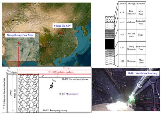
Figure 1.
Location and layout of 91–101 ventilation roadway of Wang-Zhuang Coal mine.
2.2. Basic Supporting Parameter of Roadway
The section of the 91–101 ventilate roadway is rectangular, with a width of 5500 mm, a height of 3500 mm, and an area of 19.8 m2. The original support parameters are described below.
2.2.1. Roof Support
Anchor bolt: Each row is equipped with seven high-strength rebar steel anchor bolts with a diameter of 22 mm and a length of 2400 mm. The length of the anchorage end is 1500 mm, and the anchor lockset is a high-strength steel plate with a length of 150 mm, width of 150 mm, thickness of 10 mm, and arch height of 36 mm. The anchor bolts have a row spacing of 900 mm and a spacing of 850 mm. The anchor bolt at the top corner position is 200 mm away from the coal wall with an incline toward both coal walls of 15°. A metal mesh is laid between the anchor plate and the roof and connected by a set of double-reinforced double beam ladders, each with a diameter of 14 mm and a length of 80 mm. Anchor cable: The anchor cable is a large-aperture prestressed cable with a diameter of 18.9 mm, a hole depth of 8000 mm, a length of 8300 m, and an anchorage length of 2200 mm. The anchor lockset is a high-strength steel plate with a length of 300 mm, width of 300 mm, thickness of 10 mm, and arch height of 60 mm. The anchor cables are arranged in the form of 3-2-3; the anchor cables are connected perpendicular to the roadway by a double beam ladder with a diameter of 14 mm and length of 4500 mm when the roadway cross-section is equipped with three anchor cables, and the anchor cables are connected parallel to the roadway by a double beam ladder with a diameter of 14 mm and length of 4100 mm when the roadway cross-section is equipped with two anchor cables.
2.2.2. Coal Wall Support
Seven high-strength rebar steel anchor bolts (diameter 22 mm and length 2000 mm) are equipped on both sides of the coal wall. The length of the anchorage end is 1200 mm, and the lockset is a high-strength steel plate with a length of 150 mm, width of 150 mm, thickness of 10 mm, and arch height of 36 mm. The anchor bolts in the coal wall have a row spacing of 900 mm and a spacing of 1000 mm, and the anchor bolt at the top corner position is 250 mm away from the coal roof with an incline toward the roof of 15°. A metal mesh is laid between the anchor plate and the coal wall and connected by a set of double-reinforced double beam ladders, each with a diameter of 14 mm and length of 3400 mm. The basic support structure of the roadway is shown in Figure 2.
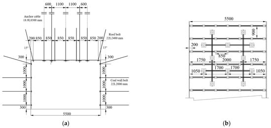
Figure 2.
Basic support structure of the 91–101 ventilation roadway. (a) Roadway section; (b) roadway roof.
2.3. Roadside Support
A basic mechanics test of the concrete-filled steel tubes was carried out in the laboratory, as shown in Figure 3a. The bearing characteristics of concrete-filled steel tubes with core sleeve structures was obtained and tested, and numerical simulation results showed that the presence of the inner cylinder not only improved the load-bearing capacity of the concrete-filled steel tube, but also ensured that the tube maintained a non-unloading state for a period of time after reaching the peak load. The compression curve of a concrete-filled steel tube with a core sleeve structure (C-CFST) is shown in Figure 3b. The roadside support of gob-side entry retaining in the 91–101 ventilation roadway uses concrete-filled steel tubes with core sleeve structures. The outer tubes are made of hot-rolled seamless steel pipe with a diameter of 1220 mm and thickness of 10 mm, and the inner tubes are made of a waste gas drainage pipe with a diameter of 425 mm and thickness of 3.5 mm, respectively, as shown in Figure 3c. In addition, C40 concrete is used to fill the steel tubes. Through laboratory tests and theoretical calculations, the stiffness and strength of the core constraints in a steel tube column with a diameter of 1220 mm were found to be approximately 37.4 GPa and 82.5 MPa, respectively.
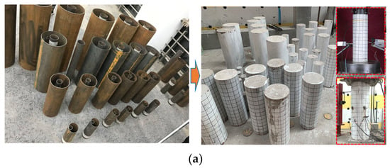
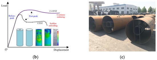
Figure 3.
Concrete-filled steel tube roadway side supports with core sleeve structures. (a) C-CFST scaling mechanical test; (b) bearing characteristic contrast of samples; (c) on-site photos of steel tubes.
3. Stability Analysis of an Integral Load-Bearing Structure of GER
3.1. Roof Structure of GER in a Fully Mechanized Top Coal Caving Longwall
The bearing characteristics of the concrete-filled steel tube enable it to limit the separation between the top coal and the roof in the early stage, so that the roadway’s surrounding ‘small structure’ rock can participate in the migration balance of overlying ‘large structure’ strata in a timely manner. In addition, the interaction between the roof and the roadside supports presents a new characteristic under discontinuous laying of concrete-filled steel tubes. During the movement of the strata, the long length of the lateral cantilever main roof causes the surrounding rock of the roadway to enter a high-stress state. The hinged balance between the main roof and the key block on the gob side is under the combined action of the roadside support resistance and the overburden pressure, which is significant to gob-side entry retaining. A structural mechanics model of this situation is shown in Figure 4.
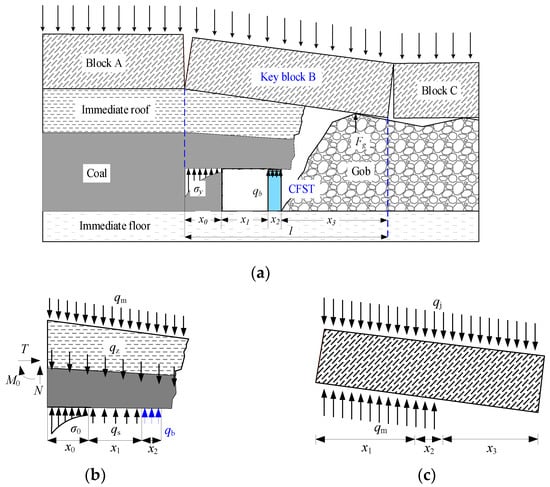
Figure 4.
Mechanical model of GER in a fully mechanized top coal caving longwall. (a) Mechanical model of GER; (b) immediate roof; (c) main roof.
The basic assumptions of this model are as follows [24,25,26]: (1) internal cracks in the immediate roof have been compacted, and the immediate roof is uniformly compressed under the overburden pressure; (2) the sliding friction between the immediate roof and top coal is neglected; (3) under the support of large-diameter, sleeve structure concrete-filled steel tubes, the immediate roof and top coal do not separate, and the deformation of the immediate roof and top coal remain coordinated. In this model, the width of the retained roadway is x1, the width of the roadside support body is x2, the length of the hanging roof is x3, and the forces include self-weight qz, overburden pressure qj, roadway basic supporting force qs, and roadside supporting force qb. Due to the interaction between the main roof and the immediate roof, it is necessary to further analyze the main roof and immediate roof separately.
Let qm be the supporting force of the immediate roof to the main roof. Before the main roof is broken, the coordinate origin point is regarded as the fixed end constraint of the main roof, and there is a constraint force that does not affect the rotation and sinking of the main roof [27,28]. The displacement of the main roof at the point above the roadside support under the combined action of two external forces is Δc, the deflection w curve equation of the cantilever beam is as follows:
Substituting the main roof weight qz, overburden pressure qj, and cantilever distance lj = x1 + x2 + x3 into Formula (1), the displacement wj of rock mass above the roadside support when qj acts alone is given by Formula (2) [27,28]:
Substituting the supporting force of the immediate roof qm and cantilever distance lz = x1 + x2 into Formula (1), the displacement wm of rock mass above the roadside support when qm acts alone can be calculated by Formula (3):
According to the deformation compatibility relation of the main roof, the displacement Δc equal to the algebraic sum of the displacement caused by qj and qm acting alone on the rock mass above the roadside support is calculated as follows:
There are unknown parameters in Formula (4); therefore, it is necessary to further analyze the force of self-weight qz, the support resistance in the roadway qs, the roadside support resistance qb, and the reaction force interacting with the main roof qm. The moment of each force to the coordinate origin O is calculated using Formula (5):
The distribution intensity of each external force acting on the immediate roof is simplified as uniform load, and by shifting the term, the following can be obtained:
By substituting Formula (6) into Formula (4), the displacement of the main roof above the roadside support under the action of various external forces can be obtained using Formula (7):
According to Formula (7), the rotary sinking of the main roof is related to the resistance of the roadside support, the support strength of the anchor bolt and anchor cable in the roadway, the overburden pressure, and the material and geometric properties of the main roof. Among these factors, except for the resistance of the roadside support and the support strength in the roadway, the other parameters cannot be controlled artificially. When the overlying rock pressure and the material properties of the main roof are kept constant, the deformation of the main roof is negatively correlated with the roadside support resistance. The reduction in roadside support resistance will cause the internal bending force in the main roof above the solid coal wall to increase sharply. In the whole system of the rock beam, the dangerous section of internal bending force is located above the solid coal wall and roadside support body, and the passive roof cutting of the main roof outside the roadway requires the roadside support body to have a high support resistance.
3.2. Interaction Mechanism of Discontinuous Arrangement Roadside Support
3.2.1. Stress Distribution between Columns
The discontinuous arrangement of concrete-filled steel tubes forms an empty roof area between the columns, as shown in Figure 5a. According to previous studies, the stability of the roof between two columns is closely related to the span of columns; excessive span will form a tensile stress area in the middle of the two columns, resulting in an uneven deformation of the shallow roof [29,30,31,32]. Meanwhile, the roadside support is located at the edge of the gob and is disturbed by multiple overburden activities. The repeated mutual extrusion of the shallow part of the roof and the roadside support will cause the roof to become broken, which is disadvantageous to gob-side entry retaining.
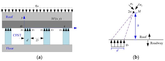
Figure 5.
Mechanical model of roof between columns. (a) Physical model of discontinuous alley side support; (b) additional stress calculation model.
The analysis of the mechanical characteristics of the roof between the columns focuses on the change in the roof along the direction of the roadway. When the change in stress in the roadway direction is continuous and gradual, the stress state of the roof above the adjacent roadside supports is basically the same [33,34,35]. Therefore, we can regard the analysis of the stress state of the roof between the columns as a mechanical problem of solving the internal stress distribution of the semi-infinite plane boundary under uniformly distributed loads. Thus, a mechanical model of the roof between two columns was established, as shown in Figure 5b, and the roof of the retained roadway was shown to be affected by support resistance and the overburden strata pressure. Before conducting the analysis of the roof between the columns, the basic assumptions on the calculation model were set as follows: (1) the model can be regarded as a plane strain problem along the direction of the roadway and (2) the supporting force of the concrete-filled steel tube to the roof is a uniform load along the direction of the roadway.
Assuming that the semi-infinite plane is subjected to a distributed load concentration qb(s) at the free boundary, the force element of unit length at the point distance from the coordinate origin O can be approximately regarded as a concentrated force with value df = qb(s)dx. Under the action of a concentrated force, the stress at any point on the semi-infinite planar body can be obtained from the theory of elastic mechanics.
The stress state at any point in the semi-infinite plane under the action of distributed load concentration qb(s) can be obtained by integrating the mechanical response of all force elements of the distributed load concentration, as seen in Formula (8).
Under the assumption that the overlying strata is isotropic elastic material, the additional stress caused by multiple adjacent concrete-filled steel tubes on the roof can be calculated by linear superposition. The additional stress caused by a discontinuous arrangement of multiple concrete-filled steel tubular columns in the roof can be calculated using Formula (9):
Taking the geological condition of the 91–101 working panel as the background, the relevant parameters were substituted into Formula (9) to calculate the additional stress in the roof between the columns, and a vertical stress contour map was drawn using MATLAB, as shown in Figure 6.
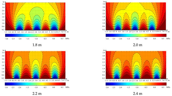
Figure 6.
Vertical stress distribution in the roof between columns with different spacing.
For the concrete-filled steel tube roadside supports, the change in spacing had a strong influence on the distribution range and extreme value of the tensile stress zone between two columns. The tensile stress zone of the roof between the columns was distributed in an arch shape; the arch feet were located at the edge of the concrete-filled steel tubes, and the arch crown was located at the middle line between the two columns. The roof of the roadway in the top caving working panel was coal rock full of cracks, which is prone to tensile damage and leads to instability in the whole load bearing structure. Thus, reasonable spacing must be controlled to ensure the stability of the rock mass between columns. It can be seen from Figure 6 that when the spacing between columns was 1.8 m, the tensile stress zone between columns was within the range of 0.3 m of the roof’s depth. However, when the spacing reached 2.0 m, the tensile stress zone between columns extended to the range of 1.2 m of depth; when the spacing reached 2.2 m, the tensile zone between columns extended to the range of 2.2 m of depth, and when the spacing reached 2.4 m, the range of tensile zone between columns was greater than 2.6 m of depth, which exceeds the control depth of the basic anchor bolt support system of the 91–101 ventilation roadway. Thus, to ensure the stability of the roof between columns and the whole roadside support system, the spacing between the concrete-filled steel tubes should not be greater than 2.2 m.
3.2.2. Roof-Support Body Shear Failure Mechanism
Assuming that the contact surface between the roadside support body and the roof is in a limit equilibrium state, the limit equilibrium zone of the roof above the roadside support can be divided into three parts: (1) The area directly above the roadside support body is zone Ⅰ, in which the contact surface is the maximum principal stress surface, the pressure in the vertical direction of the roadside support body is the maximum principal stress, and the horizontal stress perpendicular to the depth direction of the roof is the minimum principal stress. The two sets of shear surface and the roadway roof present an angle of (45 + φ/2)°, as shown in Figure 7a. (2) As the pressure of the “large structure” of the overlying strata diverges to the “small structure”, zone Ⅰ is squeezed to both sides, and zone Ⅲ becomes a passive state zone due to the horizontal stress acting as the maximum principal stress. The shear surface is also composed of two groups of planes, and because the roof surface becomes the minimum principal stress plane, the shear surface and the roof surface present an angle of (45 − φ/2)°. (3) The middle of zone Ⅰ and zone Ⅲ is the transition zone Ⅱ. One of the shear surfaces of zone Ⅱ is the radiation line, and the other is the logarithmic spiral curve, as shown in Figure 7b.
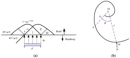
Figure 7.
Shear slip surface of roadway roof. (a) Shear slip surface-radiation line; (b) shear slip surface-logarithmic spiral line.
In Formula (10), r represents the distance from the point O to any point m, r0 is the distance of On along any selected axis, θ is the angle between On and Om, and the radius of curvature corresponding to any point m is angle φ with the normal direction of the logarithmic spiral curve.
The theoretical formula of the limit load of roadway roof is given in Formula (11):
Where c represents the cohesion of rock mass of the roadway roof and φ represents the angle of internal friction. When qb < qu, the rock mass at the contact surface between the roadside support body and the roof will not be sheared to failure. Additionally, it can be seen from Formula (11) that the limit load of rock mass at the contact surface between the roadside support body and the roof is positively related to the φ and c of the roof rock mass. As the overburden pressure and the properties of rock mass are uncontrollable factors, three reinforcement measures can be considered to ensure that the contact surface between the roadside support and roof does not suffer shear failure: (1) increasing the contact area between the roadside support body and the roof of the roadway; (2) pre-grouting the roadway roof to increase the c, φ value of the rock mass; and (3) pre-setting the additional anchor cable in advance of the working longwall. Calculations were carried out by substituting the geological parameters of the 91–101 working longwall, and the results showed that, assuming the load borne by the concrete-filled steel tube reaches 80% of its ultimate load, the diameter of the concrete-filled steel tube must be greater than 980 mm to ensure that the roof and floor of the roadway do not undergo shear failure.
4. Analyses of Discontinuous Supporting in Gob-Side Entry Retention
To explore the deformation law of the surrounding rock mass of gob-side entry retaining with large-diameter, concrete-filled steel tube roadside supports, a numerical model was established with the geologic parameters of the 91–101 working panel of Wang-Zhuang Coal Mine, as shown in Figure 8. The three-dimensional size was given by a length, width, and height of 205 m, 128 m, and 18 m, respectively. The diameter of the concrete-filled steel tube was 1.2 m. The model consisted of 961,280 units and 984,330 nodes. A uniform vertical stress of about 10 MPa was applied at the top of the model to represent the weight of overburden rock, the lateral pressure coefficient was set as 1.2, and the factors of the anchor bolts and cables support were not considered in this article. The model was set up with slip boundaries around the perimeter and fixed boundaries at the bottom. In addition, in order to clarify the impact of the concrete-filled steel tubes’ future strength development on the deformation of the retained roadway surrounding rock, the model took into account the strength development characteristic of the concrete and servo-assigned the parameters of the concrete-filled steel tubes with the excavation.
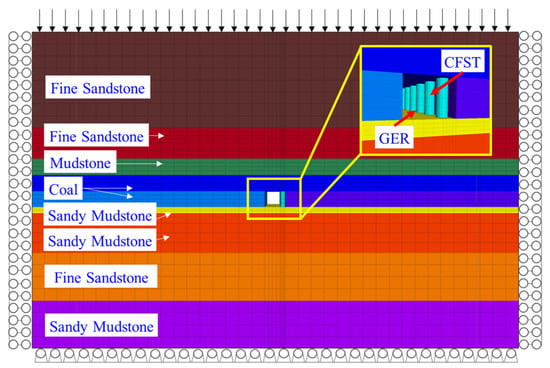
Figure 8.
Numerical model.
The constitutive model of rock stratum adopted the Mohr–Coulomb model, and the corresponding parameters of each rock stratum are shown in Table 1.

Table 1.
Physical and mechanical parameters of numerical model stratum.
Due to the fact that no built-in constitutive model of FLAC can accurately represent the mechanical properties of concrete-filled steel tubes, this study assumed the steel tube material as being in an elastic state and adopted an elastic constitutive model. Meanwhile, according to the literature, the strain-softening model is appropriate for concrete materials restrained by steel tubes, which reflects the diverse post-peak properties of concrete-filled steel tubes by setting the relationship between the cohesion and the internal friction angle and plastic shear strain. Table 2 and Table 3 show the parameters corresponding to the elastic and plastic stages of the strain-softening model.

Table 2.
Elastic parameters of the strain-softening model.

Table 3.
Plastic parameters of the strain-softening model.
The double yield model was adopted for the goaf, and the stiffness of broken rock in the goaf increased with the decrease in the volume of fractured rock, which is expressed as an increase in support to the overlying strata.
The vertical displacements of the roof in the mining direction under different column spacings are shown in Figure 9. The cloud map shows that as the spacing of columns increased, the displacement of the roof and floor between the columns also increased. The area directly above the concrete-filled steel tubes was in a compression state, and the maximum tensile stress value of the roof and floor between the columns was sensitive to the change in column spacing. With the increase in column spacing, the maximum tensile value also increased. In order to make the arrangement of non-continuous supports achieve the effect of continuous wall roadside supports, the compressive stress field in the roof directly above the columns and the roof between the columns must form an “intersection circle” at the shallow part of the roadway roof and floor.
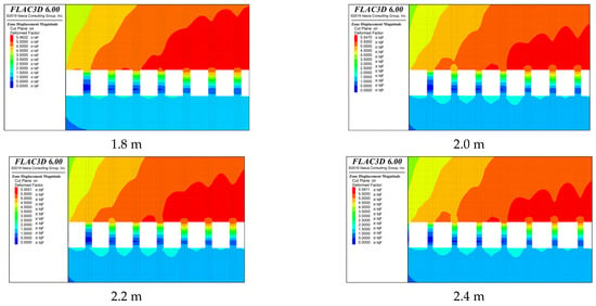
Figure 9.
Displacement distribution characteristics of surrounding rock under different columns spacing.
The displacement of the roof in the section perpendicular to the mining direction under different column spacing was extracted for analysis, and the section plane was located in the middle line between the roadside support columns, as shown in Figure 10. Under different column spacing conditions, the difference in roof displacement in the deep part of the solid coal wall was small. This part of the roof is above the elastic core area of the solid coal wall. However, looking at the roof above the solid coal wall from the deep to shallow end, the difference in roof subsidence caused by column spacing became gradually obvious. When the column spacing was 1.8 m, the roof subsidence above the surface of the solid coal wall and middle line of the roadway were about 200 mm and 240 mm, respectively, and when the column spacing was 2.4 m, the roof subsidence above the surface of the solid coal wall and middle line of the roadway reached about 300 mm and 370 mm, respectively. In addition, as the column spacing increased from 1.8 m to 2.4 m, the rate of growth of the roof subsidence above the concrete-filled steel tube roadside support body increased continuously. For different geological conditions, adopting the optimal spacing of concrete-filled steel tube (CFST) columns can improve the economy, reduce labor intensity, and ensure the stability of the retained roadway.
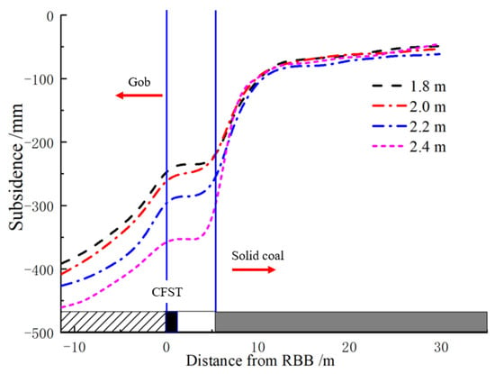
Figure 10.
Roof subsidence with difference columns spacing.
5. Field Application
Field tests were carried out in the 91–101 working panel of Wang-Zhuang Coal Mine in Chang Zhi City. Through underground field observation, it could be seen that the deformation of surrounding rock in the roadway advance longwall area and the concrete pouring area could be controlled using the following methods: (1) temporarily strengthening the support and grouting the rock mass modification in the roadway advance longwall area; (2) rapidly connecting the concrete-filled steel tube column and roof; (3) modifying the concrete with early strength agents, etc. The structural deformation in the active zone of the roof is the deformation that appears in the later stage of gob-side entry retaining, which can be controlled by adjusting the parameter of the concrete-filled steel tubes and optimizing the span of the columns. In this study, specific construction technical parameters are proposed after field investigation and calculation to achieve the purpose of optimizing construction process, improving working quality, optimizing overburden structure, increasing surrounding rock strength, and reducing the load acting on hydraulic props. The specific support forms and parameters of gob-side entry retaining in the 91–101 ventilation roadway are as follows.
5.1. Pre-Strengthening Treatment of Roof
- (1)
- Pre-strengthening of the roof between the hydraulic supports of the working longwall: three rows of anchor cables with specs Φ22L7300 mm are set on both sides of 2# and 3# hydraulic support, with a spacing of 1600 mm. The combination of 8# channel steel with a length of 300 mm and a steel plate with a length of 120 mm, width of 60 mm, and thickness of 12 mm is adopted to the anchor lockset. An anchor exposed end length of 250 mm and not less than 200 KN of pre-tightening force of the anchor cable is required.
- (2)
- Roadway roof strengthening: a group of anchor cables with specs Φ22L7300 mm are set on the roadway roof close to the gob side. Two anchor cables are in each group, one of them being 200 mm away from the roadside support body side, and the other being 1500 mm away from the roadside support body side. Two anchor cables are linked by a double-reinforced steel strip with a length of 1600 mm, and the spacing between each group of anchor cables is 1800 mm in the mining direction. The steel plate with a length of 300 mm, width of 300 mm, and thickness of 16 mm is adopted to the lockset of the anchor cable, and not less than 200 KN of pre-tightening force of anchor cable is required.
5.2. Process of Roadway Retaining
According to the previous analysis, when the spacing was selected as 2.2 m, the tensile stress area between the columns was within the range of the anchor bolt support system; thus, the on-site spacing of the concrete-filled steel tubes was selected as 2.2 m. Π-beams with a length of 5000 mm and single-hydraulic props were installed 30 m ahead of the working longwall for temporary reinforcement of support in the roadway. Each Π-beam was matched with two single-hydraulic props and arranged vertically to the direction of the mining, as shown in Figure 11.
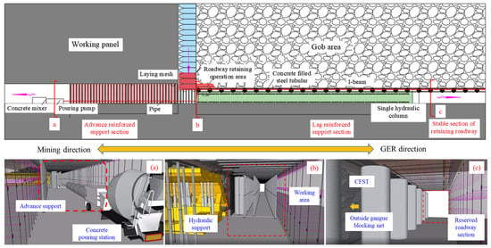
Figure 11.
Process of gob-side entry retaining with large-diameter, concrete-filled steel tubes in a fully mechanized working panel. (a) Advanced section of working face; (b) CFST construction area; (c) retained roadway.
Anchor-cable-suspended I-beams with a length of 1800 mm were used to strengthen the rock mass of the roof between the concrete-filled steel tube columns. In the roadway retained behind the working longwall, two 3000 mm long Π-beams were arranged on the both sides; each Π-beam was matched with three hydraulic props and the spacing of the Π-beams, perpendicular to the mining direction, were 200 mm and 2900 mm, respectively. The Π-beams + hydraulic props were arranged 60–100 m behind the working longwall, and whether to withdraw the Π-beams + hydraulic props was determined according to the field condition of pressure and deformation of the roadway roof. A double-deck steel wire mesh was laid in front of the five groups of hydraulic supports at the end of the working longwall, overlapping with steel wire mesh in the roadway. The construction process of concrete-filled steel tubes is presented in Figure 12.
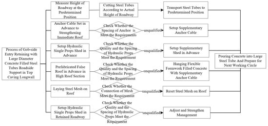
Figure 12.
Flow chart of CTST gob-side entry retaining.
5.3. Effects of Gob-Side Entry Retaining with CFST
The convergence deformation of the roof and bottom of the roadway was measured using a deep base displacement meter. The 91–101 working longwall has an average of five production cycles per day with a mining advance of 0.8 m per cycle, and the footage of roadway retaining is 4.0 m per day. Monitoring stations A and B were set up in the middle of the retained roadway for monitoring the deformation of the roof and floor of the retained roadway during the mining. Monitoring station A was located 370 m from the open-off cut point, and monitoring station B was located 680 m from the open-off cut point. Figure 13 shows the displacement curves of the two monitoring points.
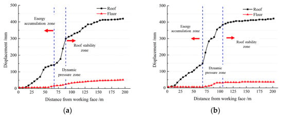
Figure 13.
Displacement curves of retained roadway roof and floor. (a) Monitoring point A; (b) monitoring point B.
As can be seen from Figure 14, the deformations of the roof and floor of the retained roadway at the two monitoring points showed the same characteristics, which can be divided into three stages. Stage 1: When the monitoring point was located 0–65 m behind the working longwall, the deformations of the roof and floor showed slowly increasing trends. The maximum deformation of the roof located 65 mm behind the working longwall reached about 150 mm, and there was basically no floor heave in the range of 0–65 m behind the longwall. Stage 2: When the monitoring point was 75 mm behind the working longwall, the point entered the dynamic pressure influence zone and the roof of the roadway subsided dramatically in a short time, accompanied by floor heave. Stage 3: When the monitoring point was more than 105 m behind the working longwall, the velocity of the roadway roof deformation slowed down, gradually approaching stability. The final subsidence of the roof was about 430 mm, and the floor heave value reached about 80 mm.
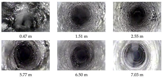
Figure 14.
Screenshots taken from video obtained down boreholes at different depths.
The roof of the retained roadway was probed at monitoring point A, as shown in Figure 14. It can be seen from the figure that the shallow part of the roadway roof was broken, the hole wall was relatively intact at a depth of 1.51 m, the position of the coal–rock interface was reached at a depth of 2.55 m, and there was no separation at the coal–rock interface. At the depth of 5.77 m, it can be seen that there were ring and longitudinal cracks in the hole wall. At the depth of 7.03 m, the rock masses were intact. The depth of the anchorage end of the anchor cable in the 91–101 ventilation roadway was greater than 7 m; therefore, the strength of the roadway anchorage system was less affected by roof activities, and the stability of the retained roadway roof was good. Figure 15 shows the realistic view of gob-side entry retaining with large-diameter, concrete-filled steel tubes in the 91–101 ventilation roadway.

Figure 15.
Realistic view of gob-side entry retaining in 91–101 working longwall. (a) CFST construction area; (b) T-junction of working longwall; (c) retained roadway.
6. Conclusions
This paper, taking the 91–101 ventilation roadway of Wang-Zhuang Coal Mine as the engineering background, studied the deformation characteristics of the surrounding rock mass of gob-side entry retaining with large-diameter, concrete-filled steel tube roadside support in a fully mechanical top caving working panel. The following conclusions were drawn:
- Considering the high strength an adaptability requirements of the roadside supports for roof deformation in gob-side entry retaining in a top caving longwall, large-diameter, sleeve-structured, concrete-filled steel tubes have been proposed as a roadside support body. According to the surrounding rock large-structure characteristics of gob-side entry retaining in a fully mechanized top caving working panel, a mechanical model was established, and a calculation method for roof subsidence was obtained.
- A mechanical analysis model of roof rock mass between columns was established to clarify the distribution form of the tensile stress zone, and the Prandtl foundation failure criterion was introduced to determine the critical condition of shear-slip instability in the contact surface between the concrete-filled steel tubes and the roof, which provided a design basis for the stability control and support scheme for the roof between columns.
- Aiming at the difficulty of surrounding rock control of gob-side entry retaining in a top caving longwall, the process and parameters of gob-side entry retaining with large-diameter, concrete-filled steel tube roadside support were put forward, which effectively guarantee the safe and efficient construction of gob-side entry retaining.
- Field tests were carried out in the 91–101 ventilation roadway. The roadside support of gob-side entry retaining in the 91–101 ventilation roadway consists of concrete-filled steel tubes with a core sleeve structure; the outer tube is made of a hot-rolled seamless steel pipe with a diameter of 1220 mm and thickness of 10 mm, and the inner tube is made of a waste gas drainage pipe with a diameter of 425 mm and thickness of 3.5 mm, respectively. The deformations of the roof and floor of the roadway were monitored and the results showed that the deformations of the retained roadway roof and floor could be divided into three stages: slow deformation stage, dynamic pressure influence stage, and gradual stability stage. The maximum subsidence of the retained roof reached about 430 mm, and the floor heave of the retained roadway reached 80 mm. The roof probe results showed that the main roof above the roadway was relatively intact, and the basic roadway support system was still in a stable state. The area of the retained roadway section reached 12.9 m2.
In summary, this technology is an important breakthrough in the technical field of non-pillar mining and can be used to reduce the waste of coal pillars and improve the recovery rate of coal resources.
Author Contributions
Conceptualization, Z.-L.L. and Z.-G.M.; methodology, Z.-L.L. and O.I.K.; software, Y.L.; formal analysis, P.G.; investigation, Z.-L.L. and P.G.; writing—original draft preparation, Z.-L.L.; writing—review and editing, Z.-G.M. and X.-Y.N. All authors have read and agreed to the published version of the manuscript.
Funding
This research was funded by the National Key Research and Development Projects of China, under Grant Nos. 2019YEE0118500 and 2019YFC1904304; Natural Science Foundation of Jiangsu Province, under Grant No. BK20200634; The Natural Science Foundation of the Jiangsu Higher Education Institutions of China, under Grant Nos. 21KJB130004; National Natural Science Foundation of China, under Grant Nos. 52104107 and 51734009.
Institutional Review Board Statement
Not applicable.
Informed Consent Statement
Not applicable.
Data Availability Statement
The data used to support the finding of this study are included within the article.
Conflicts of Interest
The authors declare no conflict of interest.
References
- Tan, Y.L.; Yu, F.H.; Ning, J.G.; Zhao, T.B. Design and construction of entry retaining wall along a gob side under hard roof stratum. Int. J. Rock Mech. Min. 2015, 77, 115–121. [Google Scholar] [CrossRef]
- Xie, S.; Pan, H.; Chen, D.; Zeng, J.; Song, H.; Cheng, Q.; Xiao, H.; Yan, Z.; Li, Y. Stability analysis of integral load-bearing structure of surrounding rock of gob-side entry retention with flexible concrete formwork. Tunn. Undergr. Space Technol. 2020, 103, 103492. [Google Scholar] [CrossRef]
- Li, J.Z.; Zhang, M.; Li, Y.; Hu, H. Surrounding rock control mechanism in the gob-side retaining entry in thin coal seams, and its application. J. S. Afr. Inst. Min. Metall. 2018, 118, 471–480. [Google Scholar] [CrossRef]
- Bai, J.; Shen, W.; Guo, G.; Wang, X.; Yu, Y. Roof Deformation, Failure Characteristics, and Preventive Techniques of Gob-Side Entry Driving Heading Adjacent to the Advancing Working Face. Rock Mech. Rock Eng. 2015, 48, 2447–2458. [Google Scholar] [CrossRef]
- Guo, P.; Yuan, Y.; Ye, K.; Sun, D. Fracturing mechanisms and deformation characteristics of rock surrounding the gate during gob-side entry retention through roof pre-fracturing. Int. J. Rock Mech. Min. 2021, 148, 104927. [Google Scholar] [CrossRef]
- Qi, F.; Ma, Z.; Yang, D.; Li, N.; Li, B.; Wang, Z.; Ma, W. Stability Control Mechanism of High-Stress Roadway Surrounding Rock by Roof Fracturing and Rock Mass Filling. Adv. Civ. Eng. 2021, 2021, 6658317. [Google Scholar] [CrossRef]
- He, M.; Gao, Y.; Yang, J.; Gong, W. An Innovative Approach for Gob-Side Entry Retaining in Thick Coal Seam Longwall Mining. Energies 2017, 10, 1785. [Google Scholar] [CrossRef]
- Wang, Q.; He, M.; Yang, J.; Gao, H.; Jiang, B.; Yu, H. Study of a no-pillar mining technique with automatically formed gob-side entry retaining for longwall mining in coal mines. Int. J. Rock Mech. Min. 2018, 110, 1–8. [Google Scholar] [CrossRef]
- Yang, J.; He, M.; Cao, C. Design principles and key technologies of gob side entry retaining by roof pre-fracturing. Tunn. Undergr. Space Technol. 2019, 90, 309–318. [Google Scholar] [CrossRef]
- Zhang, X.; Chen, L.; Gao, Y.; Hu, J.; Yang, J.; He, M. Study of An Innovative Approach of Roof Presplitting for Gob-Side Entry Retaining in Longwall Coal Mining. Energies 2019, 12, 3316. [Google Scholar] [CrossRef]
- Wang, Y.; Wang, Q.; He, M.; Hou, S.; Yang, J.; Gao, Y. Stress and deformation evolution characteristics of gob-side entry retained by the N00 mining method. Geomech. Geophys. Geo-Energy Geo-Resour. 2021, 7, 84. [Google Scholar] [CrossRef]
- Sun, X.; Zhao, C.; Zhang, Y.; Chen, F.; Zhang, S.; Zhang, K. Physical model test and numerical simulation on the failure mechanism of the roadway in layered soft rocks. Int. J. Min. Sci. Technol. 2021, 31, 291–302. [Google Scholar] [CrossRef]
- Cheng, S.; Ma, Z.; Gong, P.; Li, K.; Li, N.; Wang, T. Controlling the Deformation of a Small Coal Pillar Retaining Roadway by Non-Penetrating Directional Pre-Splitting Blasting with a Deep Hole: A Case Study in Wangzhuang Coal Mine. Energies 2020, 13, 3084. [Google Scholar] [CrossRef]
- Wang, P.; Ding, L.; Ma, Y.; Feng, T.; Sun, G.; Zhu, Y.; Ren, H.; Li, P.; Zhang, Y.; Wang, X.; et al. A Case Study on Gob-Side Entry Retaining Technology in the Deep Coal Mine of Xinjulong, China. Adv. Civ. Eng. 2020, 2020, 8849093. [Google Scholar] [CrossRef]
- Qi, F.; Yang, D.; Zhang, Y.; Hao, Y. Analysis of Failure Mechanism of Roadway Surrounding Rock under Thick Coal Seam Strong Mining Disturbance. Shock Vib. 2021, 2021, 9940667. [Google Scholar] [CrossRef]
- Zhang, G.; Li, Q.; Zhang, Y.; Du, F. Failure characteristics of roof in working face end based on stress evolution of goaf. Geomech. Geophys. Geo-Energy Geo-Resour. 2021, 7, 53. [Google Scholar] [CrossRef]
- Liu, S.M.; Sun, H.T.; Zhang, D.M. Nuclear magnetic resonance study on the influence of liquid nitrogen cold soaking on the pore structure of different coals. Phys. Fluids 2023, 35, 012009. [Google Scholar] [CrossRef]
- Xie, S.; Wang, E.; Chen, D.; Sun, Y.; Cheng, Q.; Ji, C.; Yan, Z.; Xiao, H. Failure analysis and control mechanism of gob-side entry retention with a 1.7-m flexible-formwork concrete wall: A case study. Eng. Fail. Anal. 2020, 117, 104816. [Google Scholar] [CrossRef]
- Huang, W.; Wang, X.; Shen, Y.; Feng, F.; Wu, K.; Li, C. Application of concrete-filled steel tubular columns in gob-side entry retaining under thick and hard roof stratum: A case study. Energy Sci. Eng. 2019, 7, 2540–2553. [Google Scholar] [CrossRef]
- Qu, G.L.; Gao, Y.F.; Yang, L.; Xu, B.J.; Liu, G.L.; Meng, D.J. Strength Assessments of Concrete-Filled Steel Tubular Support of Soft Rock Roadway. Adv. Mater. Res. 2013, 838–841, 1884–1890. [Google Scholar] [CrossRef]
- Chen, P.; Wang, Y.; Zhang, S. Size effect prediction on axial compression strength of circular CFST columns. J. Constr. Steel Res. 2020, 172, 106221. [Google Scholar] [CrossRef]
- Li, Y.; Yang, S.Q.; Li, Y. Experiment and numerical simulation on cracking behavior of marble containing double elliptic holes under uniaxial compression. Theor. Appl. Fract. Mech. 2021, 112, 102928. [Google Scholar] [CrossRef]
- Li, Y.; Yang, S.Q.; Liu, Z.L.; Sun, B.W.; Yang, J.; Xu, J. Study on mechanical properties and deformation of coal specimens under different confining pressure and strain rate. Theor. Appl. Fract. Mech. 2022, 118, 103287. [Google Scholar] [CrossRef]
- Yang, H.Y.; Cao, S.G.; Wang, S.Q.; Fan, Y.C.; Wang, S.; Chen, X.Z. Adaptation assessment of gob-side entry retaining based on geological factors. Eng. Geol. 2016, 209, 143–151. [Google Scholar] [CrossRef]
- Deng, Y.H.; Tang, J.X.; Zhu, X.K.; Fu, Y.; Dai, Z.L. Analysis and application in controlling surrounding rock of support reinforced roadway in gob-side entry with fully mechanized. Int. J. Min. Sci. Technol. 2010, 6, 841–845. [Google Scholar] [CrossRef]
- Palchik, V. Bulking factors and extents of caved zones in weathered overburden of shallow abandoned underground workings. Int. J. Rock Mech. Min. Sci. 2015, 79, 227–240. [Google Scholar] [CrossRef]
- Zhang, Y.Q.; Tang, J.X.; Xiao, D.Q. Spontaneous caving and gob-side entry retention of thin seam with large inclined angle. Int. J. Min. Sci. Technol. 2014, 24, 441–445. [Google Scholar] [CrossRef]
- Li, W.F.; Bai, J.B.; Peng, S.S. Numerical modeling for yield pillar design: A case study. Rock Mech. Rock Eng. 2015, 48, 305–318. [Google Scholar] [CrossRef]
- Kazanin, O.I.; Ilinets, A.A. Ensuring the excavation workings stability when developing excavation sites of flat-lying coal seams by three workings. J. Min. Inst. 2022, 253, 41–48. [Google Scholar] [CrossRef]
- Zubov, V.P.; Phuc, L.Q. Development of resource-saving technology for excavation of flat-lying coal seams with tight roof rocks (on the example of the quang ninh coal basin mines). J. Min. Inst. 2022, 257, 795–806. [Google Scholar] [CrossRef]
- Zubov, V.P.; Golubev, D.D. Prospects for the use of modern technological solutions in the flat-lying coal seams development, taking into account the danger of the formation of the places of its spontaneous combustion. J. Min. Inst. 2021, 250, 534–541. [Google Scholar] [CrossRef]
- Sidorenko, A.A.; Sidorenko, S.A.; Ivanov, V.V. Numerical modelling of multiple-seam coal mining at the taldinskaya-zapadnaya-2 mine. ARPN J. Eng. Appl. Sci. 2021, 16, 568–574. [Google Scholar]
- Zuev, B.Y.; Istomin, R.S.; Kovshov, S.V.; Kitsis, V.M. Physical modeling the formation of roof collapse zones in vorkuta coal mines. Bull. Miner. Res. Explor. 2020, 162, 225–234. [Google Scholar] [CrossRef]
- Sidorenko, A.A.; Ivanov, V.V.; Sidorenko, S.A. Numerical simulation of rock massif stress state at normal fault at underground longwall coal mining. Int. J. Civ. Eng. Technol. 2019, 10, 844–851. [Google Scholar]
- Phuc, L.Q.; Dmitriev, P.N.; Van Duy, T.; Yunpeng, L. Influence of the main roof on the parameters of the abutment pressure zone in the selvedge of the seam. Min. Inf. Anal. Bull. 2022, 6, 68–82. [Google Scholar] [CrossRef]
Disclaimer/Publisher’s Note: The statements, opinions and data contained in all publications are solely those of the individual author(s) and contributor(s) and not of MDPI and/or the editor(s). MDPI and/or the editor(s) disclaim responsibility for any injury to people or property resulting from any ideas, methods, instructions or products referred to in the content. |
© 2023 by the authors. Licensee MDPI, Basel, Switzerland. This article is an open access article distributed under the terms and conditions of the Creative Commons Attribution (CC BY) license (https://creativecommons.org/licenses/by/4.0/).