Abstract
Increased volumes of freight turnover in international transportation require the situational adaptation of the existing wagon fleet to the transportation of containers, which are commonly used at present. The research presented in this article substantiates the possibility of transporting containers in open wagons. It has been found that taking into account the possible displacements of containers in the body, the stresses at the operating modes can be twice as high as the permissible ones if an open wagon is part of the combined train. In this regard, it is proposed that a detachable multifunctional module for securing containers in the open wagon body be used. The detachable module is fixed through the fitting stops, either stationary or hinged, in the body. The rationale for the choice of the detachable module profile, as well as the results of its strength calculation, is given. The strength of the open wagon body during container transportation has been studied taking into account the proposed fastening diagram. The results of the calculations have shown that the maximum stresses in the body do not exceed permissible values. The results of the study will contribute to improvement in the efficiency of container transportation and the transport industry as a whole. Also, these results may be useful developments for designing modular vehicles.
1. Introduction
The development of transportation towards international transport corridors requires the introduction of vehicles intended for different types of freight. It is known that containers are frequently used for international freight transportation. Mostly they are transported on flat wagons. There are special flat wagons equipped with fitting stops for fastening containers. The lack of special flat wagons for container transportation has stimulated the modernization of the existing flat wagon fleet by mounting stationary or hinged fitting stops. At the same time, higher rates of freight transportation in international traffic have led to a shortage of flat wagons. In this regard, there is a need for the situational adaptation of other wagon types to be used for container transportation. And one of these wagons is the open wagon (Figure 1).
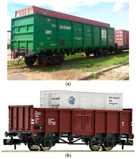
Figure 1.
Containers in (a) a 1520 mm gauge open wagon, Reprinted with permission from Ref. [1]. 2023, Rail.insider; (b) a 1425 mm gauge open wagon, Reprinted with permission from Ref. [2]. 2023, EURO TRAIN HOBBY.
As a rule, a typical open wagon design is not adapted to container transportation. This can cause structural failures in operation at certain load modes, as well as a risk to the safety of freight transportation. Therefore, in order to increase the efficiency of freight transportation in international traffic, it is expedient to study the possibility of the situational adaptation of open wagon bodies to container transportation.
The stability of containers on wagons during transportation can be ensured by means of lashing devices. Usually, wagons are equipped with fitting stops, both stationary and hinged, which are attached to the wagon frame.
In order to increase the efficiency of container transportation, new fastening diagrams are being developed. Thus, in [3], a special flat wagon for container transportation is proposed. Its special feature is vertical racks that provide the container stability during transportation.
Green Brier Europe offers the wagon design for the transportation of road cars, minibuses, as well as containers [4]. This wagon is equipped with wheel stops for fastening road vehicles. When transporting containers, these stops are dismantled, and special folding elements are installed on the wagon frame. The wagon design is in conformity with international standards.
However, these transportation technologies are very costly, since they require the introduction of new vehicle designs.
An assembly for securing containers in the open wagon body is proposed in [5]. It consists of the base plate, pin support in the form of a profile, rod element with a rounded top, and flat side faces. It also includes an axis, thrust plate, eyelet, tube, bottom plate, and fixing elements. This assembly has a rather complex configuration, which will cause difficulties in maintenance and repair. In addition, when a wagon moves along the rail track, an additional load on the body can occur due to its interaction with the assembly components.
The patent in [6] presents a load assembly for fastening freight, including containers, for railway transportation. The assembly contains a frame base, dividing partition, and first support for the freight. The partition is located at the end of the frame base. The first support for freight and the partition form the support channel. The first support consists of the first upper beam, first shock-absorbing element, and first stiffener. One end of the first shock-absorbing element is connected to the lower beam, and its second end is connected to the first upper beam. The lower part of the first stiffener rests against the upper side of the frame base. The first stiffener side rests against the first lower beam and/or the first shock-absorbing element. However, this assembly design does not allow the open wagon to be adapted to the safe transportation of containers by rail.
In [7], the authors propose the modernized bearing structure of the wagon intended for the transportation of containers by installing fitting stops. The results of experimental studies into the strength of the bearing structure of a wagon at the most unfavorable operating loads are presented. It is demonstrated that the proposed modernization ensures the strength of the bearing structure of the wagon.
Peculiarities of modernization of the wagon for container transportation are covered in [8]. The authors propose the use of a detachable frame to accommodate 20- and 40-foot containers. The results of the strength calculation of the frame are presented. It was found that the proposed design solutions are appropriate. It should be noted that this modernization was implemented on the example of flat wagons. In case of their shortage, it is advisable to use this modernization for other wagon types, including open wagons, it being the most common wagon type in operation.
The authors of studies [9,10] propose the use of detachable modules for the situational adaptation of wagons to the transportation of various types of freight, including containers. These modules operate as swap bodies. The structural features of these detachable modules were substantiated and the strength was calculated at main operational load modes. At the same time, these modules are adapted to transportation on flat wagons, which narrows the demand for them.
Of scientific interest is [11], in which the authors propose the design of the wagon for the combined transportation of various types of freight both in the body and in containers to avoid empty runs. The wagon for combined trains has a frame, running gears with bogies, coupler devices, braking devices, and a body. Here, the body is made in the form of an open wagon with the side and end walls and the bottom. The wagon frame is equipped with stops to secure containers. The stops are installed in the corners of the body and can be either fitting stops or any other.
In [12], a similar design of a wagon is proposed; it contains a body with the frame resting on bogies. The body consists of the end and sidewalls, and the frame has fitting stops for containers. To guide the container during its loading and unloading, corner guide rails are installed on the end walls. Side guide rails are installed on the sidewalls. The side guide rails are located at an angle to the sidewall and can be removed. The corner guide rails consist of two parts.
It should be noted that if containers are fastened according to the diagrams given in [11,12], the load from them is transferred to the body as concentrated loading, i.e., at four points. The technological gaps between the stops and the fittings can induce the container’s own degree of freedom during transportation. This increases the load, not only on its structure, but also on the fitting stop, which can cause its damage.
In article [13], the authors discuss the issues of the systematic and dynamic approach to assessing the effectiveness of the interconnection of trans-border transport infrastructure. A mathematical model was developed that made it possible to determine the quantitative variables. The features of testing this model and its application for the Hong Kong–Zhuhai–Macau Bridge are also given.
An overview of modern approaches to improving the efficiency of transport is covered in [14]. The authors classify all types of methods for analyzing traffic monitoring. Macro-transport flows and micro-road behavior were taken into account.
Also of interest is study [15], in which a new model for forecasting a traffic flow is proposed. This model combines visual methods of quantifying the macroscopic parameters of traffic flow, the density function in time, and the flow feedback in spatial characteristics.
It is important to say that the approaches developed and proposed in [13,14,15] were not considered in relation to rail container transportation, which would also improve operation efficiency.
2. Objective and Main Tasks of the Research
The objective of the research is the situational adaptation of the bearing structure of the open wagon to safe container transportation by rail. To achieve the objective the following tasks were set:
- To determine the dynamic load and the strength of the open wagon body when transporting containers;
- To offer the detachable module design for securing containers in the open wagon body;
- To determine the dynamic load and the strength of the open wagon body during container transportation by taking into account the proposed fastening diagram.
3. Determination of the Dynamic Load and the Strength of the Open Wagon Body When Transporting Containers
The load of the open wagon body when transporting containers was determined with mathematical modeling. For it, the mathematical model given in [16] was applied. However, this model was improved because the study mentioned presented only research into the dynamic load of the flat wagon transporting liquid cargo in tank containers; therefore, the freight had compliance in the middle of the tank.
In our study, it was taken into account that two 1CC containers were placed in the open wagon. The design diagram is shown in Figure 2.
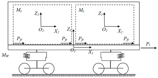
Figure 2.
Design diagram of the open wagon loaded with containers.
This model was compiled using the second-order Lagrange equation, which included that the open wagon loaded with containers moved longitudinally. At the same time, the force Pl = 2.5 MN [17] was applied to the front stops of the couplers, which corresponded to the “stretch–jerk” mode, as one of the most unfavorable in terms of the force action. It should be noted that there is an international document that is similar to the normative document [17]; however, it contains the values of longitudinal loads [18] that are mainly applicable for 1435 mm gauge wagons. As far as the work deals with the transportation of containers in 1520 mm gauge wagons, this stage of the study was based on standards from [17].
It was taken into account that the open wagon body rested on standard bogies of model 18-100. In this regard, the model included the absolute friction force arising in the spring suspension.
In the zones of interaction between the containers and the open wagon, the friction forces (steel–steel) were taken into account.
The model included three degrees of freedom of the open wagon and the containers, which characterized the longitudinal load, the angular load around the transverse axis, and the vertical displacement. Moreover, the containers had the same load and symmetrical displacements relative to the open wagon. The movement of the freight in the container was neglected.
Then, the mathematical model that described the movement of the open wagon looked like:
where M′W is the weight of the open wagon; MW is the weight of the bearing structure of the open wagon; h is the height of the center of gravity of the body; IW is the moment of inertia of the open wagon relative to the longitudinal axis; Pl is the value of the longitudinal force to the coupler; Pfr is the friction force emerging between the container fittings and the open wagon floor; l is a half of the open wagon base; PFR is the absolute value of the dry force in the spring group; k1, k2 are the rigidities of springs in the spring group of the open wagon bogies; mc is the container weight; zci is the height of the center of container weight; Ic is the moment of inertia of the i-th container; xW, ϕW, and zW are the coordinates corresponding to the longitudinal, angular around and transverse axis, and vertical displacements of the open wagon, respectively; xi, ϕi, and zi are the coordinates corresponding to the longitudinal, angular around the transverse axle, and vertical displacements of the container, respectively; and Fz is the vertical force arising between the container and the wagon body.
It should be noted that this model was verified. Previous publications of the authors have conducted theoretical and experimental studies of the load of a flat wagon with containers [19]. The model was verified with the F-test. In this research, the model was adapted so as to determine the load of an open wagon loaded with containers.
When determining the input parameters of the mathematical model, the physical and geometric parameters of the open wagon model 12-295 were taken into account; this wagon was considered as a prototype, as well as a standard 1CC container.
The open wagon’s body weight was taken equal to 14.6 tons, the moment of inertia was 308 t∙m2, and the wagon base was 8.65 m. The rigidity of the spring suspension of the bogie was 8000 kN/m, and the relative friction coefficient was 0.1 These parameters of the spring suspension correspond to the standard parameters of the bogie model 18-100; i.e., they correspond to its technical characteristics.
The weight of the container was 24 tons and the moment of inertia was 220.3 t∙m2. The height of the container was 2.35 m.
The irregularity of the track was neglected in the model, since a short-term disturbance (pulse) corresponding to the “stretch–jerk” mode was taken into account.
The mathematical model was solved using the Runge–Kutta method [20,21,22] in MathCad [23,24,25]. To do this, mathematical model (1) was reduced to the normal Cauchy form, which was integrated with a fixed step using the classical algorithm for solving equations presented in [26].
The initial conditions were taken equal to zero [27,28,29]. The results of the calculation showed that the maximum accelerations acting on the constrainer were about 34 m/s2, and those on the open wagon—about 36 m/s2 (Figure 3). The resulting acceleration value can be explained by the fact that the container was not fastened in the body and had its own degree of freedom. This acceleration value is consistent with that presented in the research by Prof. Bogomaz [16]. However, this concerned the longitudinal dynamics of the flat wagon loaded with tank containers. Moreover, his calculation included the displacements of the tank containers due to the gaps between the fittings and the fitting stops.
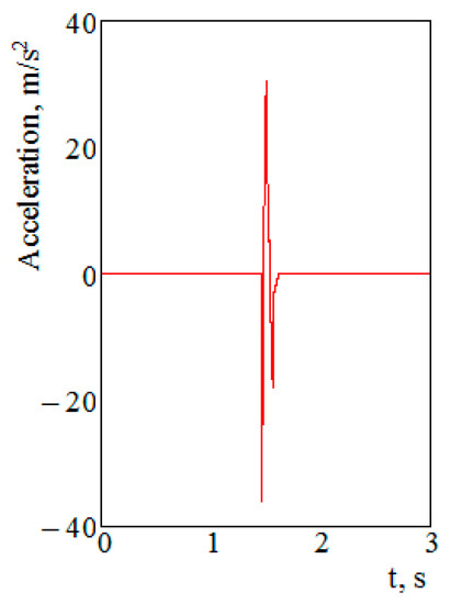
Figure 3.
Accelerations on the open wagon.
The resulting acceleration value was taken into account when calculating the strength of the bearing structure of the open wagon. The calculation was implemented using the finite element method in SolidWorks Simulation [30,31]. This method was chosen for the calculation since it is the most popular for the calculation of machine-building structures.
Based on the corresponding drawings, a spatial model of the supporting structure of the open wagon was built (Figure 4). A 12-295 solid-bottom open wagon was chosen as a prototype.
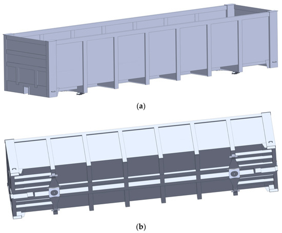
Figure 4.
Spatial model of the bearing structure of the open wagon: (a) top view; (b) bottom view.
When creating a spatial model of the wagon body, the elements that strictly interacted with each other were taken into account. The welding seams were not included; i.e., the model was considered a monolithic structure.
When creating a continuous model, three-dimensional elements, tetrahedrons, were used. The mesh was created on a solid body. The number of nodes was 786,565, and the number of elements—2,410,633. The maximum size of the element was 25 mm, the minimum—5 mm.
The design diagram of the open wagon body (Figure 5) took into account the following loads: vertical Pv, longitudinal Plst applied to the end wall, as well as longitudinal Pl applied to the stops of the coupler and balanced on the opposite side by the forces of the inertia of the wagon weight.
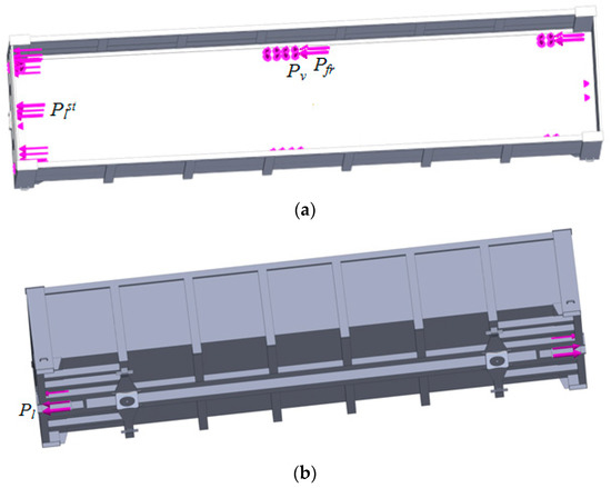
Figure 5.
Design diagram of the bearing structure of the open wagon: (a) top view; (b) bottom view.
The vertical load Pv was applied to the wagon bottom through the plates, the geometry of which was identical to the geometry of the container fittings. It was taken into account that the bearing structure of the open wagon was loaded with four 1CC containers. In this case, the total value of the vertical load Pv from one container to four plates was taken equal to 240 kN, which corresponded to the gross weight of one container. The load was applied to the entire surface of the plates. In these zones, the longitudinal frictional forces Pfr, which emerged due to the displacement of the container relative to the floor, were taken into account. The value of these forces per container was taken equal to 94.2 kN, and the “steel–steel” friction coefficient was 0.4.
The value of the longitudinal load Plst, which acted on the end wall, was determined using the value of the longitudinal acceleration acting on the container. This force was considered to be evenly distributed over the end wall. The longitudinal force Pl, which was applied to the stops of the coupler, was taken equal to 2.5 MN. This force was also considered to be evenly distributed over the vertical surface of the stop.
It was taken into account that the container was not fastened to the body, but rested on the floor. This meant that the option when the container was not fastened to the body was also included.
The body was fastened at the horizontal surfaces of the center plates, which modeled the interaction of the body with the bogie.
The Mises criterion was used for the calculation [32,33,34,35]. The results of the calculation are given in Figure 6 and Figure 7. The maximum stresses in the bearing structure of the open wagon were recorded in the zone of interaction between the transverse belts of the end wall and the corner posts; they amounted to 387.2 MPa. The resulting stresses were almost twice as high as permissible ones, which, for design mode I, were 310.5 MPa [17].
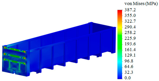
Figure 6.
Stress state of the bearing structure of the open wagon.
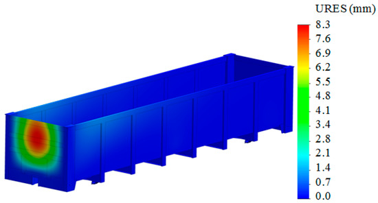
Figure 7.
Displacements in the units of the bearing structure of the open wagon.
The maximum displacements in the structural units were recorded in the upper part of the end wall—8.3 mm. This was because the lower and lateral parts interacted with the body frame, and the upper one was free.
The calculation has demonstrated that if the containers are not fastened to the wagon body, the structural strength of the wagon is not ensured. In this regard, there is a need to implement solutions aimed at ensuring the stability of containers during their transportation in open wagons.
4. Structural Features of the Detachable Module for Securing Containers in the Open Wagon Body
The authors have proposed a detachable module design for fastening containers to the open wagon body (Figure 8). The module includes central beam 1, side beams 2, transverse beams 3, end beams 4, and telescopic cantilever element 5. Containers are fastened with fitting stops 6 to the module, and the module is fastened to the wagon body with fittings 7.
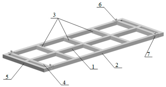
Figure 8.
Detachable module for fixing containers in the open wagon.
The placement of the module in the open wagon is shown in Figure 9. It can be fastened through the corner fitting under fitting stop 6 (through corner holes). This fastener is identical to those used for a typical container. However, it is necessary to provide detachable fitting stops in the open wagon body, which are frequently used in flat wagons for the transportation of containers. Cantilever part 5 is telescopic, which allows the length of the module to be adjusted depending on the inner length of the open wagon body. This will help ensure the immobility of the module at the operating modes as part of the train. The placement of the container on the module is shown in Figure 10, and that in the open wagon—in Figure 11. The container was fastened to the module the same way as in the flat wagon, i.e., through the fittings placed in the corner parts.
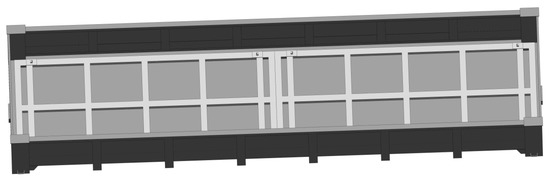
Figure 9.
Placement of modules for fixing containers in the open wagon body.
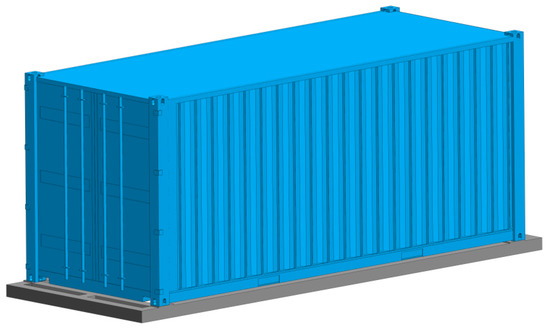
Figure 10.
Placement of the container on the module.
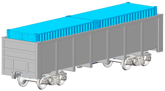
Figure 11.
Placement of containers in the open wagon body.
It should be noted that this module could operate on the principle of the detachable open-type module FLAT RACK [9], which increases its functionality in operation (Figure 12). To secure the freight, the module can be additionally equipped with appropriate brackets, clamps, etc.
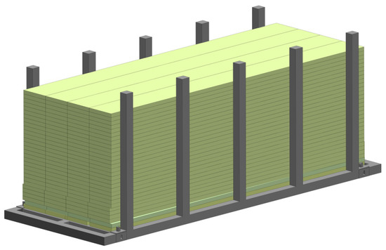
Figure 12.
Module loaded with timbers.
The longitudinal dynamic load of the detachable module was determined using mathematical modeling. In this case, mathematical model (1) was reduced to the following form
where is the weight of the open wagon loaded with containers; is the weight of the bearing structure of the open wagon, loaded with containers; is the moment of inertia of the open wagon loaded with containers relative to the longitudinal axis; and , , and are the coordinates corresponding to longitudinal, angular around the transverse axis, and vertical displacements of the open wagon loaded with containers, respectively.
That is, the model neglected the containers’ own degree of freedom. Therefore, the containers placed on the module were considered as attached masses that repeated the trajectory of the open wagon body. The solution of the mathematical model under the initial conditions equaling zero demonstrated that the acceleration acting on the open wagon was 31.2 m/s2. The acceleration value obtained was 13% lower than that acting on it if containers were not fastened to the body.
This acceleration value was taken into account when choosing the detachable module profile. The calculation was carried out in LIRA-SAPR [36]. The detachable module was studied as a rod system on four supports in the areas where the fittings were placed. The longitudinal loading diagram of the module was taken into account since the main purpose of its application is to eliminate displacements of the containers in the longitudinal plane. They might occur due to technological gaps between container fittings and fitting stops.
When drawing the design diagram of the module, it was taken into account that the longitudinal load Pl, caused by the forces of inertia, acted on the telescopic cantilever part (Figure 13). This load was applied on one side of the module; i.e., it simulated its leaning against the end wall of the open wagon. The calculation was carried out under the condition that the module was loaded with a 1CC standard container.
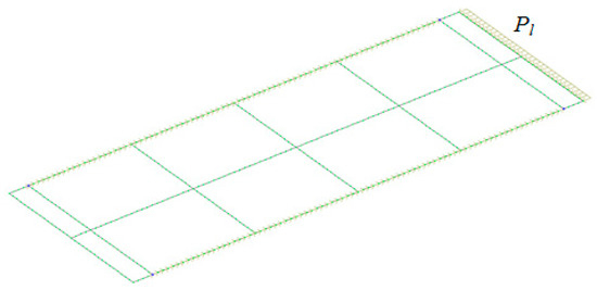
Figure 13.
Design diagram of the detachable module.
The diagram of the longitudinal forces of the detachable module was obtained based on the calculation (Figure 14).
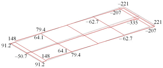
Figure 14.
Longitudinal force diagram (kN).
The maximum value of the longitudinal force was recorded in the middle beam of the cantilever part and amounted to 335 kN.
The diagram of module deformation on an enlarged scale (24:1) is shown in Figure 15. Thus, when the cantilever beam perceived the longitudinal load, the longitudinal and transverse beams moved in the opposite direction from the force action. However, these movements were quite low and did not reach 1 mm.
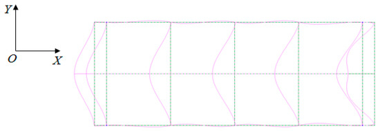
Figure 15.
Diagram of module deformation under the longitudinal load.
The cross-section area of the profile was determined according to the longitudinal force value [37,38]
where F is the longitudinal force acting on the module; [σ] is the permissible stresses.
Taking into account that the profile is made of Steel 09G2C, the value F = 32.03 cm2 is obtained with a safety margin of n = 2.0. It is advisable to use a square pipe with a width and height of 110 mm, which has a cross-sectional area of 8.5 cm2 [39,40]. The weight of 1 m of pipe is 25.14 kg. With this in mind, the weight of the detachable module is about 960 kg.
This profile is chosen because, technologically, it is substantively optimal in manufacture and operation. Also, such a profile has the same moment of resistance relative to the vertical and horizontal axes, which is important so that the strength of the structure can be ensured.
Based on the graphic works, a spatial model of the module for securing containers in the open wagon body was created and its strength was calculated. The design diagram included the vertical load Pv acting on the detachable module from the weight of the containers (Figure 16), the longitudinal loads, Pl and Pl f, conditioned by the forces of inertia and applied, respectively, to the fitting stops from the containers, as well as to the fittings from the fitting stops placed in the open wagon body. The value of the vertical force Pv was taken to be equal to 240 kN. The longitudinal force Pl was about 187 kN. Since the force Pc was the reaction to the force Pl, their values were equal.
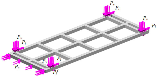
Figure 16.
Design diagram of the module.
Also, the model included the longitudinal load Pc in the zones of interaction between the module and the end wall of the open wagon body.
The module was secured at the corner fittings. Here, a rigid fixing was used. Such securing was justified by the fact that the cantilever part of the module rested on the end wall of the open wagon, which compensated for the module’s own degree of freedom in the longitudinal plane.
When compiling a finite-element model of the module, spatial tetrahedrons were used. The mesh was built taking into account the appropriate compaction in the zones of rounding and interfaces of the structural elements of the module. The number of elements of the mesh was determined with the graphic-analytical method. In this case, the mesh was formed with 46,828 elements. The number of nodes was 15,305. The maximum size of the element was 60 mm, the minimum—12 mm. The model was fastened in the areas of support on the fitting stops placed in the open wagon body. Steel 09G2S was used as a construction material, which is typical in wagon building for the manufacture of bearing structures of vehicles. The results of the calculation showed that the maximum stresses occurred in the zones of fittings and were 176.1 MPa (Figure 17 and Figure 18), i.e., in the zones where the detachable module was fixed. It is important to say that these stresses did not exceed permissible values.
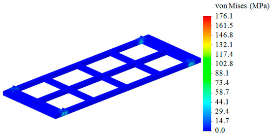
Figure 17.
Stress state of the module.
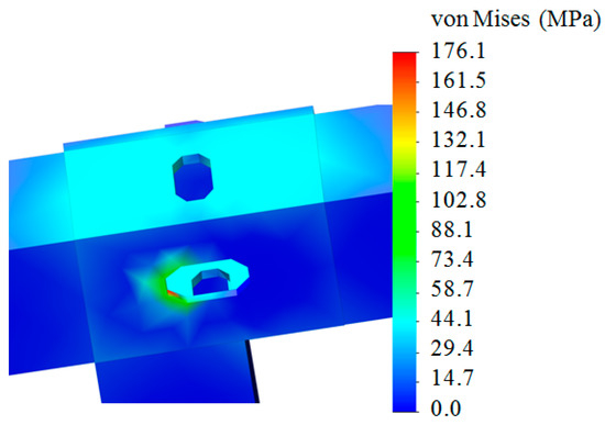
Figure 18.
Stress state of a fitting stop of the module.
The maximum displacements were recorded in the longitudinal beams of the detachable module and they amounted to 2.78 mm (Figure 19).
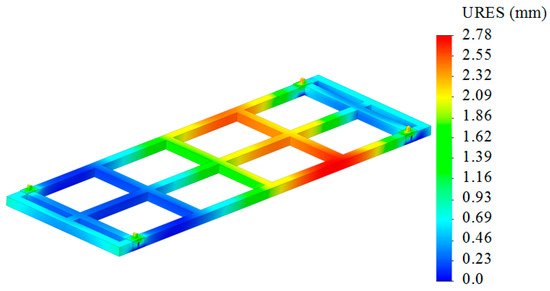
Figure 19.
Displacements in the module units.
5. Determination of the Dynamic Load and the Strength of the Open Wagon Body during Container Transportation by Taking into Account the Proposed Fastening Diagram
The strength of the bearing structure of the open wagon loaded with containers was calculated using the new fastening diagram. The design diagram of the open wagon is shown in Figure 20. It was taken into account that the vertical load Pv acted on the open wagon body and was transferred to it through the module fittings. This load was taken to be equal to 24 kN and evenly distributed over four plates, which simulated the zone on the floor on which the module rested in the open wagon. Also, the longitudinal load Pl, caused by the forces of inertia, was applied to the end wall in the direction of the movement. This load was determined taking into account the acceleration obtained by means of mathematical model (2) and applied to the end wall through the plate and simulated the zone of interaction between the module and the wall.
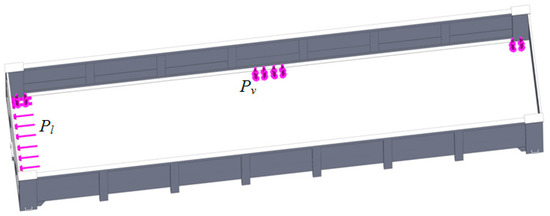
Figure 20.
Design diagram of the open wagon body.
The longitudinal load was applied to the front stops of the coupler balanced on the opposite side by the forces of inertia of the wagon masses. The load value was taken—2.5 MN. The model was fastened at the center plates.
The body was fastened at the horizontal surfaces of the center plates.
Tetrahedrons were used in the finite-element model. The number of nodes was 786,565, and the number of elements—2,410,633. The maximum size of the element was 25 mm, the minimum—5 mm. The results of the calculation are given in Figure 21, Figure 22 and Figure 23. The maximum stresses occurred in the lower part of the end wall and they amounted to 196.2 MPa (Figure 20 and Figure 21), which did not exceed permissible values.
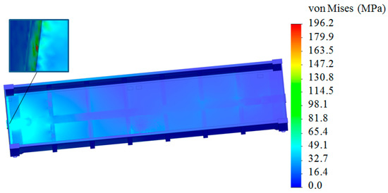
Figure 21.
Stress state of the open wagon body (top view).
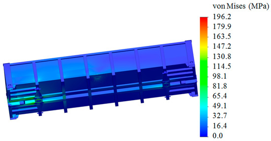
Figure 22.
Stress state of the open wagon body (bottom view).
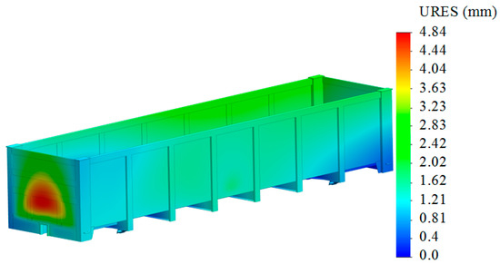
Figure 23.
Displacements in the units of the open wagon body (top view).
The maximum displacements were recorded in the end wall of the body and amounted to 4.84 mm (Figure 23).
These stresses can be reduced by using an energy-absorbing material for the cantilever part of the module or strengthening the lower part of the end wall with a horizontal belt.
6. Results and Discussion
In order to use open wagons for the transportation of containers, appropriate studies were carried out. At the first stage, the dynamic load of the open wagon with containers in the “stretch–jerk” mode was investigated. The accelerations that act on the open wagon in this case were determined. Their numerical value was about 36 m/s2 (Figure 3). The resulting acceleration was taken into account when calculating the strength of the open wagon body. The finite element method was used for the calculation. It was implemented in SolidWorks Simulation. It was found that the strength of the open wagon body, which was not technically adapted for the transportation of containers, was not ensured. The maximum equivalent stresses were 387.2 MPa (Figure 6), which exceeds permissible values.
In this regard, the design of a detachable module was proposed to ensure the situational adaptation of the open wagon for the transportation of containers (Figure 8). This module is installed in the open wagon body for fastening the containers. It should be noted that the authors have filed an application for a patent for this module.
To select design profiles of the detachable module, the strength taken using the rod system was calculated. At the same time, LIRA-SAPR software was used. The results obtained made it possible to determine the loading diagrams (Figure 13 and Figure 14) and, thus, select the module profile. The strength of the detachable module was calculated. It was found that the stresses in its design do not exceed permissible values (Figure 17 and Figure 18), which has allowed us to prove that the choice of the selected profiles was justified.
The next stage of the study included the determination of the load of the open wagon body taking into account the proposed fastening diagram for containers. The calculations confirmed the efficiency of the solutions studied. Taking into account the new fastening diagram for containers, it was found that the stresses in the open wagon body did not exceed permissible values and amounted to 196.2 MPa (Figure 22).
However, the authors did not consider the issues of transitional operation modes for the open wagon with containers when part of a train. These issues will be addressed in further studies.
The advantage of this study, if compared to those analyzed in Section 1 of this article, is that the proposed solution will contribute not only to the situational adaptation of the open wagon to the transportation of containers but also, if necessary, to the detachable modules being used as autonomous cargo units for various types of freight, which will stimulate the demand for them in the transport industry.
The further stage of this research will be the experimental determination of the strength of the open wagon body when transporting containers. The strength of the detachable module, while being transported by various modes of transport, also requires attention in order to justify its operation efficiency.
7. Conclusions
- The dynamic load and the strength of the open wagon body when transporting containers are determined. It was found that the maximum accelerations acting on the container are about 34 m/s2, and on the open wagon—about 36 m/s2. The results of the strength calculation for the open wagon body show that the maximum stresses in its structure arise in the zone of interaction between the transverse belts of the end wall and the corner posts; they are 387.2 MPa. The resulting stresses are almost twice as high as the permissible ones, which, for design mode III, are 210 MPa.
- The design of a detachable module for securing containers in the open wagon body is proposed. This module can operate on the principle of the detachable open-type module FLAT RACK, which increases its functionality in operation. To determine the profile of the detachable module, it was calculated as a rod system in LIRA-SAPR. A square pipe with a width and height of 110 mm, which has a cross-sectional area of 8.5 cm2, was proposed as the detachable module profile. With this in mind, the weight of the detachable module will be about 960 kg.
- The results of the strength calculation for the detachable module show that the maximum stresses occur in the areas of fittings, and they are 176.1 MPa; that is, they do not exceed the permissible values. The maximum displacements are recorded in the longitudinal beams of the removable module and amount to 2.78 mm.
- The dynamic load and the strength of the open wagon body during the transportation of containers were determined using the proposed fastening diagram. It was found that the maximum stresses occur in the lower part of the end wall and are 196.2 MPa, which does not exceed the permissible values. The maximum displacements are recorded in the end wall of the body, and they amount to 4.84 mm.
- The conducted studies will contribute to improving the efficiency of container transportation and the transport industry as a whole. Also, the results of the research will be useful developments for designing modular vehicles.
Author Contributions
Conceptualization, J.G. and A.L.; methodology, G.V. and A.L.; software, A.L.; validation, A.L. and M.P.; investigation, A.L., M.P. and O.K.; resources, A.L. and O.K.; writing—original draft preparation, A.L., M.P. and O.K.; writing—review and editing J.G., A.L. and S.S.; visualization, G.V., A.L. and O.K.; supervision, J.G. and S.S. All authors have read and agreed to the published version of the manuscript.
Funding
This publication was issued thanks to support from the Cultural and Educational Grant Agency of the Ministry of Education of the Slovak Republic in the project “Implementation of modern methods of computer and experimental analysis of properties of vehicle components in the education of future vehicle designers” (Project No. KEGA 036ŽU-4/2021). This research was also supported by the Slovak Research and Development Agency of the Ministry of Education, Science, Research and Sport of the Slovak Republic in Educational Grant Agency of the Ministry of Education of the Slovak Republic in the project and VEGA 1/0513/22 “Investigation of the properties of railway brake components in simulated operating conditions on a flywheel brake stand. Funded by the EU Next Generation EU through the Recovery and Resilience Plan for Slovakia under the project No. 09I03-03-V01-XXXXX” and project “Scholarships for Excellent Researchers Threatened by the Military Conflict in Ukraine”, code 09I03-03-V01.
Institutional Review Board Statement
Not applicable.
Informed Consent Statement
Not applicable.
Data Availability Statement
Not applicable.
Conflicts of Interest
The authors declare no conflict of interest.
References
- At Certain Stations of the Russian Railways, Containers Will Be Transported in Semi-Wagons. Available online: https://www.railinsider.com.ua/na-okremyh-dilnyczyah-rzhd-kontejnery-perevozytymut-u-pivvagonah/ (accessed on 25 March 2023).
- Gondola Car Type Es with Container. Available online: https://www.eurotrainhobby.com/fleischmann-gondola-car-type-es-with-con/p14742c459 (accessed on 25 March 2023).
- Zhao, Z.; Wang, X.; Cheng, S.; Liu, W.; Jiang, L. A New Synchronous Handling Technology of Double Stake Container Trains in Sea-Rail Intermodal Terminals. Sustainability 2022, 14, 11254. [Google Scholar] [CrossRef]
- Laaers L04A. 2×2-Axle Wagon, Series Laadgrs–Open Flat Car Carrier and Container Twin Wagon. Available online: https://www.greenbrier-europe.com/2022/10/08/laaers-l04a-2x2-axle-wagon-series-laadgrs-open-flat-car-carrier-and-container-twin-wagon/ (accessed on 25 March 2023).
- Savushkin, R.A.; Kyakk, K.W.; Kononenko, A.S.; Vladimirov, A.V.; Lyalenko, D.A. Device for Fastening Containers. Russian Patent No. 177439 U1 RU, 13 July 2018. (In Russian). [Google Scholar]
- Li, Z.; Dong, Z.; Sun, Y. Loading Device. Russian Patent No. 2756738 C RU, 27 June 2019. (In Russian). [Google Scholar]
- Reidemeister, A.G.; Kalashnyk, V.A.; Shikunov, A.A. Modernization as a method of improving the use of universal wagons. Science and progress of transport. Bull. Dnipropetr. Natl. Univ. Railw. Transp. 2016, 2, 148–156. (In Ukrainian) [Google Scholar] [CrossRef]
- Shaposhnyk, V.; Shykunov, O.; Reidemeister, A.; Leontii, M.; Potapenko, O. Determining the possibility of using removable equipment for transporting 20- and 40-feet-long containers on an universal platform wagon. East.-Eur. J. Enterp. Technol. 2021, 1, 14–21. [Google Scholar] [CrossRef]
- Panchenko, S.; Gerlici, J.; Vatulia, G.; Lovska, A.; Pavliuchenkov, M.; Kravchenko, K. The Analysis of the Loading and the Strength of the FLAT RACK Removable Module with Viscoelastic Bonds in the Fittings. Appl. Sci. 2023, 13, 79. [Google Scholar] [CrossRef]
- Vatulia, G.; Lovska, A.; Pavliuchenkov, M.; Nerubatskyi, V.; Okorokov, A.; Hordiienko, D.; Vernigora, R.; Zhuravel, I. Determining patterns of vertical load on the prototype of a removable module for long-size cargoes. East.-Eur. J. Enterp. Technol. 2022, 6, 21–29. [Google Scholar] [CrossRef]
- Yushchenko, V.V. Wagon for Combined Transportation. Russian Patent No. 180512 U2 RU, 14 June 2018. (In Russian). [Google Scholar]
- Kravchenko, A.N.; Vedyankin, A.V.; Chekodanov, E.V. Freight Car. Russian Patent No. 196252 U2 RU, 21 February 2020. (In Russian). [Google Scholar]
- Yang, B.; Wu, G.; Yuan, H. System Dynamics Approach for Evaluating the Interconnection Performance of Cross-Border Transport Infrastructure. Adv. Eng. Inform. 2023, 57, 102039. [Google Scholar] [CrossRef]
- Chen, J.; Wang, Q.; Cheng, H.H.; Peng, W.; Xu, W. A Review of Vision-Based Traffic Semantic Understanding in ITSs. IEEE Trans. Intell. Transp. Syst. 2022, 23, 11. [Google Scholar] [CrossRef]
- Chen, J.; Xu, M.; Xu, W.; Li, D.; Peng, W.; Xu, H. A Flow Feedback Traffic Prediction Based on Visual Quantified Features. IEEE Trans. Intell. Transp. Syst. 2023. [Google Scholar] [CrossRef]
- Bogomaz, G.I.; Mekhov, D.D.; Pilipchenko, O.P.; Chernomashentseva, Y.G. Loading of tank-containers located on a railway platform during impacts on the automatic coupler. Collect. Sci. Pract. Dyn. Rotat. Mech. Syst. 1992, 87–95. (In Russian) [Google Scholar]
- DSTU 7598:2014; Freight Wagons. General Requirements for Calculations and Design of New and Modernized Wagons of 1520 mm Track (Non-Self-Propelled). UkrNDNTS: Kiev, Ukraine, 2015; 162p.
- EN 12663-2; Railway Applications–Structural Requirements of Railway Vehicle Bodies–Part 2: Freight Wagons. BSI: Sofia, Bulgaria, 2010; 54p.
- Vatulia, G.; Gerlici, J.; Lovska, A.; Fomin, O.; Okorokov, A.; Pavliuchenkov, M.; Petrenko, D.; Kravchenko, O. Experimental Studies on the Strength of a Flatcar during Shunting Impacts. Appl. Sci. 2023, 13, 4901. [Google Scholar] [CrossRef]
- Sobolenko, O.V.; Ivashchenko, Y.S. Methods of Solving Mathematical Problems in the Mathcad Environment; NmetAU: Dnipro, Ukraine, 2020; 60p. (In Ukrainian) [Google Scholar]
- Goolak, S.; Liubarskyi, B.; Riabov, I.; Lukoševičius, V.; Keršys, A.; Kilikevičius, S. Analysis of the Efficiency of Traction Drive Control Systems of Electric Locomotives with Asynchronous Traction Motors. Energies 2023, 16, 3689. [Google Scholar] [CrossRef]
- Goolak, S.; Liubarskyi, B.; Lukoševičius, V.; Keršys, R.; Keršys, A. Operational Diagnostics System for Asymmetric Emergency Modes in Traction Drives with Direct Torque Control. Appl. Sci. 2023, 13, 5457. [Google Scholar] [CrossRef]
- Riabov, I.; Goolak, S.; Kondratieva, L.; Overianova, L. Increasing the energy efficiency of the multi-motor traction electric drive of an electric locomotive for railway quarry transport. Eng. Sci. Technol. Int. J. 2023, 42, 101416. [Google Scholar] [CrossRef]
- Fomin, O.; Lovska, A.; Skurikhin, D.; Nerubatskyi, V.; Sushko, D. Special Features of the Vertical Loading on a Flat Car Transporting Containers with Elastic-Viscous Links in their Interaction Units. In Proceedings of the 26th International Scientific Conference, Transport Means 2022 Part I, Kaunas, Lithuania, 5–7 October 2022; pp. 629–633. [Google Scholar]
- Nalapko, O.; Shyshatskyi, A.; Ostapchuk, V.; Mahdi, Q.A.; Zhyvotovskyi, R.; Petruk, S.; Lebed, Y.; Diachenko, S.; Velychko, V.; Poliak, I. Development of a method of adaptive control of military radio network parameters. East.-Eur. J. Enterp. Technol. 2021, 1, 18–32. [Google Scholar] [CrossRef]
- Yu, V.D.; Chernyak, G.Y. Fundamentals of Wagon Dynamics; KUETT: Kyiv, Ukraine, 2003; 269p. (In Ukrainian) [Google Scholar]
- Lovskaya, A. Assessment of dynamic efforts to bodies of wagons at transportation with railway ferries. East. Eur. J. Enterp. Technol. 2014, 3, 36–41. [Google Scholar] [CrossRef]
- Dižo, J.; Harušinec, J.; Blatnický, M. Structural Analysis of a Modified Freight Wagon Bogie Frame. MATEC Web Conf. 2017, 134, 00010. [Google Scholar] [CrossRef]
- Panchenko, S.; Gerlici, J.; Vatulia, G.; Lovska, A.; Rybin, A.; Kravchenko, O. Strength assessment of an improved design of a tank container under operating conditions. Commun.-Sci. Lett. Univ. Zilina 2023, 25, B186–B193. [Google Scholar] [CrossRef]
- Kozyar, M.M.; Feshchuk, Y.V.; Parfenyuk, O.V. Computer Graphics: SolidWorks; Oldi-Plus: Kherson, Ukraine, 2018; 252p. (In Ukrainian) [Google Scholar]
- Pustylga, S.I.; Samostyan, V.R.; Klak, Y.V. Engineering Graphics in SolidWorks; Tower: Lutsk, Ukraine, 2018; 172p. (In Ukrainian) [Google Scholar]
- Panchenko, S.; Vatulia, G.; Lovska, A.; Ravlyuk, V.; Elyazov, I.; Huseynov, I. Influence of structural solutions of an improved brake cylinder of a freight car of railway transport on its load in operation. EUREKA Phys. Eng. 2022, 6, 45–55. [Google Scholar] [CrossRef]
- Vambol, O.; Kondratiev, A.; Purhina, S.; Shevtsova, M. Determining the parameters for a 3D-printing process using the fused deposition modeling in order to manufacture an article with the required structural parameters. East.-Eur. J. Enterp. Technol. 2021, 2, 70–80. [Google Scholar] [CrossRef]
- Fomin, O.; Lovska, A.; Gorbunov, M.; Gerlici, J.; Kravchenko, K. Dynamics and strength of circular tube open wagons with aluminum foam filled center sills. Materials 2021, 14, 1915. [Google Scholar] [CrossRef]
- Lovska, A.; Fomin, O.; Píštěk, V.; Kučera, P. Dynamic load and strength determination of carrying structure of wagons transported by ferries. J. Mar. Sci. Eng. 2020, 8, 902. [Google Scholar] [CrossRef]
- Barabash, M.S.; Soroka, M.M.; Suryaninov, M.G. Nonlinear Construction Mechanics with PC Lira-Sapr; Ecology: Odesa, Ukraine, 2018; 248p. (In Ukrainian) [Google Scholar]
- Shvabyuk, V.I. Resistance of Materials; Znannia: Kyiv, Ukraine, 2016; 400p. (In Ukrainian) [Google Scholar]
- Kutsenko, A.; Bondar, M.; Chausov, M. Applied Mechanics (Resistance of Materials); Center for Educational Literature: Kyiv, Ukraine, 2019; 736p. (In Ukrainian) [Google Scholar]
- GOST R54157-2010; Steel Shapes Tubes for Metal Structures. Technical Requirements. IPK Standards Publishing: Moscow, Russia, 2012; 92p. (In Russian)
- DSTU 8940:2019; Steel Profile Pipes. Technical Conditions. UkrNDNTS: Kiev, Ukraine, 2021; 22p. (In Ukrainian)
Disclaimer/Publisher’s Note: The statements, opinions and data contained in all publications are solely those of the individual author(s) and contributor(s) and not of MDPI and/or the editor(s). MDPI and/or the editor(s) disclaim responsibility for any injury to people or property resulting from any ideas, methods, instructions or products referred to in the content. |
© 2023 by the authors. Licensee MDPI, Basel, Switzerland. This article is an open access article distributed under the terms and conditions of the Creative Commons Attribution (CC BY) license (https://creativecommons.org/licenses/by/4.0/).