Abstract
In precision farming technology, the interest of the researchers has been focused on the applications of autonomous mobile robots for agricultural operations such as planting, inspection, spraying, and harvesting. However, each autonomous robot generally performs a single agricultural task. In this context, complete autonomy in precision farming can be achieved by using coordinated multi-robot systems that can easily and safely cooperate to accomplish agricultural tasks. The efficiency of the multi-robot system depends on the number of robots, the size of the robots, the distance between each robot, the instant location and heading angle of the robots, and the size of the farmland. This paper describes the development of wireless Robot to Robot (R2R) communication system architecture and the collision avoidance algorithm for multi-robot precision farming applications. The developed system uses the fusion of a digital compass and GPS receiver for wirelessly broadcasting the spatial and temporal data of the mobile robots through WiFi. In this study, WiFi broadcasting was chosen for reasons such as the advantages of long wireless signal range and strength, not being easily affected by weather and dust, low cost, and so on. The proposed system realizes the real-time wireless broadcasting of the mobile robot information for eliminating the collision of mobile robots and improving the level of safety management. The results show that the system has flexible, reliable, and adaptable solution, and thus can increase the efficiency of the multi-robot system in precision farming applications.
1. Introduction
During the last decade, robotic systems have gained popularity for solving tedious agricultural tasks in field operations. Agricultural field operations are quite complex and different robotic systems were developed to solve these complexities in agricultural field operations, such as seeding [1], weeding [2], harvesting [3], spraying [4], and fertilizing [5]. According to a market research firm, the agricultural robots market is expected to reach from USD 4.6 billion in 2020 to USD 20.3 billion by 2025 [6]. Considering the rapid growth expectation for the agricultural robot market, it shows that the use of robots will increase in all agricultural operations within the agriculture industry in the next 5 years. On the other hand, with the widespread use of robots, the concept of multi-robots, which are programmed to collaborate and form an ecosystem, will emerge for completing agricultural tasks.
Over the next ten years, agricultural robot research needs to focus on the multi-robot systems that collaborate to successfully execute farming tasks [7]. Multi-robot systems consist of mobile robots that work together to accomplish agricultural tasks by moving around in the agricultural environment. Multi-robot systems can accomplish tasks not executable by a single mobile robot. In recent years, several researchers have investigated the development of mobile robot technology to optimize complex operations related to farming procedures and precision treatment [8,9,10]. Most of the proposed techniques are based on single-robot systems, but there are important reasons to consider multi-robot systems as a more advantageous approach for agricultural tasks. Multi-robot systems will direct the agriculture of the future due to the disadvantages of the single-robot systems such as the complexity of agricultural tasks, spatially distributed tasks, and the limited capabilities of single robots [11].
The important parts of the multi-robot system are the robot management system, anti-collision system, and real-time monitoring [12]. The multi-robot system has some advantages over single mobile robots, such as their effectiveness, efficiency, flexibility, and fault tolerance in precision farming applications [13]. The multi-robot systems are divided into two categories homogeneous and heterogeneous. In a homogeneous multi-robot system, the mobile robots each have their controller with the same mechanical structures and control mechanisms. On the other hand, in a heterogeneous multi-robot system, mobile robots may have different hardware structures and control mechanisms. Nevertheless, many agricultural applications require a heterogeneous multi-robot system. Although multi-robot systems have advantages like flexibility, scalability, and robustness in solving complex tasks for precision farming and large-scale agricultural applications, there is not much research on the use of multi-robot systems in the agricultural domain. Also, there is little research conducted on internal communication and radar system to avoid collisions for the multi-robot systems in precision farming applications.
In the literature, some theoretical studies have been reported on multi-robot systems. The first real multi-robot system test has been conducted by the RHEA (Robotics and Associated High-technologies and Equipment for Agriculture) project for precision farming applications [14]. RHEA is an EC-funded research project to create a heterogeneous multi-robot system of small, collaborative ground and air robots equipped with advanced sensors, advanced end effectors, and improved decision control algorithms for both chemical and physical pest management [15]. Emmi et al. [16] developed multi-robot system architecture for both individual robots and robots working in fleets to improve reliability, decrease complexity and costs, and permit the integration of software from different developers. Also, researchers proposed a collision avoidance algorithm to avoid collisions between robots by using the wireless master-slave communication system. Conesa-Muñoz et al. [17] described a distributed multi-level supervisor system for monitoring the operation of autonomous agricultural vehicles in agricultural tasks. The system has a real-time warning system to detect a failure or potentially dangerous situations for notifying the user. In addition, the system performs the anti-collision mechanism to prevent collisions between vehicles by taking action to avoid intersecting trajectories. Gonzalez-de-Santos et al. [18] developed the multi-robot system, which consists of heterogeneous ground and aerial robots for effective weed and pest control aimed at diminishing the use of agricultural chemical inputs, increasing crop quality, and improving the health and safety of production operators.
Wireless access to telemetry data is the current trend in precision farming technology, especially autonomous mobile robots, because of providing quickness, easiness, mobility, feasibility, and flexibility. Peer-to-peer technologies such as Bluetooth [19], ZigBee [20], and WiFi [21] are used to send data wirelessly from point to point in precision farming applications. Especially in multi-robot systems, wireless data exchange is so important for monitoring and controlling the working environment.
In the literature, there are limited studies about wireless R2R communication systems for precision farming applications. Amer et al. [22] developed an autonomous agricultural robot prototype (AgriBot) for performing various agricultural tasks such as seeding, weeding, and spraying fertilizers. The robot is communicated with the operator and other robots through a Wi-Fi communication system. Researchers reported that the basic design of an autonomous robot can work in small areas but, it can be designed to work in large areas of the field with the use of a Wi-Fi signal booster. Jian-sheng [23] proposed the WiFi wireless controlled agricultural robot system to reduce pesticides and improve spraying efficiency. The researcher used a wireless router to monitor the microcontroller core. The wireless router was used to remote control the robot and to transmit video data to the phone. The client-server-based control software was developed using Java language in the Eclipse development platform. Researchers reported that the proposed design realizes spraying pesticides by the robot without any problem and achieves good results. Brinkhoff and Hornbuckle [24] described a new agricultural sensor data gathering and logging platform based on IEEE 802.11 WiFi technology. The proposed system includes many sensor types such as weather, tank and irrigation water levels, and soil status sensing. For this reason, researchers reported that Wi-Fi is an attractive choice for their application because of the wide range of other devices that need connectivity in the system. Zant et al. [25] designed and developed a UV-Robot supervision system for controlling the robot that is used in greenhouse mildew treatment operations. Researchers reported that the position of the robot can be determined through possible Wi-Fi technology in farming areas. Pretto et al. [26] carried out a project to bridge the gap between the current and desired capabilities of agricultural robots by developing an adaptable robotic solution for precision farming that combines autonomous unmanned aerial vehicles and ground vehicles. In a designed system, each robot can communicate with others via Wi-Fi to be able to run coordinated missions between the robots. Researchers reported that the proposed solutions are easily applicable to a wide range of robots, and farm management activities.
The critical issue of the multi-robot systems is providing coordination between the mobile robots while sharing the same workspace for avoiding collision [27]. To solve this problem, mobile robots need to be informed about the temporal and spatial situations of other mobile robots working around them. Most commercial autonomous robots use different range sensors such as radar, sonar, infrared (IR) sensors, single charge-coupled device (CCD) cameras, and vision and laser scanners to detect obstacles. However, recent research shows that these sensors cannot fully detect a moving obstacle and are inadequate to acquire enough information about their environments [28]. For multi-robot systems, one of the promising solutions to improve the collision avoidance system is by integrating a two-way data exchange system R2R communication between autonomous robots.
In this paper, wireless R2R communication system architecture is proposed for eliminating the collision of mobile robots and improving the level of safety management. Also, the wireless communication system for broadcasting the mobile robots’ spatial and temporal information is designed and discussed. The developed system can be applied for communication and distributed control of agricultural ground-based mobile robots using the Wi-Fi protocol.
2. Materials and Methods
The main aim of the designed system is to create a wireless R2R communication system and collision avoidance algorithm for mobile robot-based precision farming applications. The system involves four main structures:
- Hardware structure of the communication system: This part explains the properties of hardware devices to provide WiFi (Wireless Fidelity) communication, and consists of an industrial PC, GPS receiver, and digital compass.
- Data acquisition and WiFi communication system: This part explains the data collection and conversion procedures for data getting from a GPS receiver and digital compass. And it also describes WiFi connectivity between mobile robots.
- Software implementation of R2R communication system: This part explains the developed server-client software to control all the functions of the wireless communication system such as conducting communication flow control, message routing, and data monitoring.
- Collision avoidance algorithm: This part explains and suggests a new algorithm for collision-free navigation of multiple mobile robots with differential steering systems.
The schematic of the wireless R2R communication system architecture for mobile robots in farmland is illustrated in Figure 1.
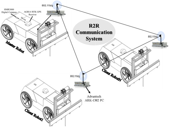
Figure 1.
Whole architecture of the wireless R2R communication system.
2.1. Hardware Structure of the Communication System
The four-wheel drive agricultural mobile robot, which was developed in our previous study [29] and can be steered both autonomously and manually, was used in this study. Advantech ARK-1382 industrial all-in-one touchscreen industrial computer (Advantech Co., Ltd., Taipei, Taiwan) was used to manage and communicate with each other all of the electronic-based equipment placed on the mobile robot. The ARK-1382 fanless and ultra-compact embedded Box PC is an embedded system engaged in edge computing and highly suitable for remote monitoring, control, and mobile applications. It was designed with Intel Core Duo 1.06 GHz processor. It is equipped with an 802.11b/g WLAN (Wireless Local Area Network) card and supports a wide range of input voltages from 9 VDC to 35 VDC. It supports 4× USB 2.0, 1× Giga LAN, and 2× COM ports.
A Topcon AGRI-4 RTK GPS (Topcon Positioning Systems, Inc., Livermore, CA, USA) receiver was used to acquire the location and speed data of the mobile robot. The receiver has up to 10 Hz data output rate. It is easily upgradeable to 2 cm accuracy with RTK radio options, and NTRIP capabilities allow it to connect to Corse-TR (Continuously Operating Reference Stations-Turkey) via a phone data card (SIM Card) to receive correction signals.
Honeywell HMR3000 digital compass was used to collect the heading, pitch, and roll data of the mobile robot. It is used for different applications such as compassing and navigation, dead reckoning backup to GPS systems, marine navigation, antenna positioning, and land surveying. This electronically gimbaled compass provides a fast refresh frequency of up to 20 Hz and a high direction accuracy of 0.5 degrees with 0.1-degree resolution. The tilt range is +/−40 degrees. The hardware components used in the communication system are shown in Figure 2.
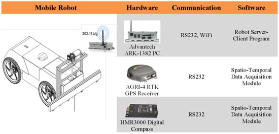
Figure 2.
Hardware components used in communication systems.
2.2. Data Acquisition and WiFi Communication System
The GPS receiver was placed in the rear right corner of each robot. The digital compass was placed in front of the mobile robot. In the study, it was seen that the digital compass did not work when placed close to the GPS receiver. The industrial computer was placed inside the body of the mobile robot. The RS-232 serial communication protocol was used for connecting the industrial computer and other electronic devices and both the GPS receiver and the digital compass have serial communication ports. The serial communication speed of the GPS receiver and the digital compass with the industrial computer was set at 19,200 baud.
NMEA (National Marine Electronics Association) 0183 protocol is a combined electrical and data specification for using communication between electronic devices such as GPS receivers, digital compass, and many other types of devices. The NMEA 0183 standard uses a simple ASCII (American Standard Code for Information Interchange), serial communications protocol that defines how data are transmitted in a “message” from one “device” to multiple “devices” at a time. There are more than 80 different types of NMEA sentences for sending GPS data. Each sentence starts with a “$” sign and the next five characters determine the sentence type. The $GPRMC sentence type is the most important sentence and included spatial and temporal data for the navigating of the mobile robots. In this study, the GPRMC sentence was used to collect latitude, longitude, and speed data of the mobile robot. Spatial data are expressed in decimal degrees or degrees, minutes, and seconds in GPRMC sentences. Although these formats are sufficient for many applications, they should be converted to UTM (Universal Transverse Mercator) coordinates for mobile robot navigation applications, mathematical calculations, and mapping. Similarly, the HMR3000 digital compass communicates with the industrial computer using a standard serial RS 232 connection using the NMEA 0183 output sentence at 19,200 baud. The NMEA 0183 sentence specifications sent by the GPS receiver and the digital compass are shown in Table 1.

Table 1.
The NMEA 0183 sentence specifications of the GPS receiver and digital compass.
The IEEE (Institute of Electrical and Electronics Engineers) 802.11 standard defines the WLAN system for providing connectivity between computers or any wireless devices capable to connect WiFi over public areas networks [30]. The IEEE 802.11b/g supports high data speeds using a 2.4 GHz frequency band and provides the speed for maximum data transmission is 5 to 54 Mbps. The computer used in this study has a built-in 802.11b/g WLAN mini PCI module. For this reason, IEEE 802.11b/g was used for communication among mobile robots.
The designed mobile multi-robot system is based on the client–server model, which allows the participation of different mobile robots and the creation of a multi-robot network. The designed system consists of a mobile robot server and one or more mobile robot clients. The robot server is responsible for authenticating the connection, listening for the incoming connections, accepting mobile robot client connections, reading the incoming data, collecting all mobile robots’ spatio-temporal data in an array, and sending out this array data to all robots. The mobile robot client is responsible for sending its spatio-temporal data to the server and requesting other mobile robots’ spatio-temporal data from the server. Multi-robot wireless communication model is shown in Figure 3.
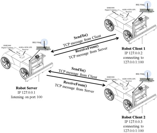
Figure 3.
Multi-robot WiFi communication system.
The client–server model is one of the most usable communication rules in networked systems. In this model, clients communicate with one server at a time. On the other hand, a server communicates with multiple clients at any point in time There are two types of communication protocol used for client–server model, they are TCP/IP (Transmission Control Protocol/Internet Protocol) communication and UDP/IP (User Datagram Protocol/Internet Protocol) communication. In this study, TCP/IP communication was used between robot server and robot clients (Figure 4).
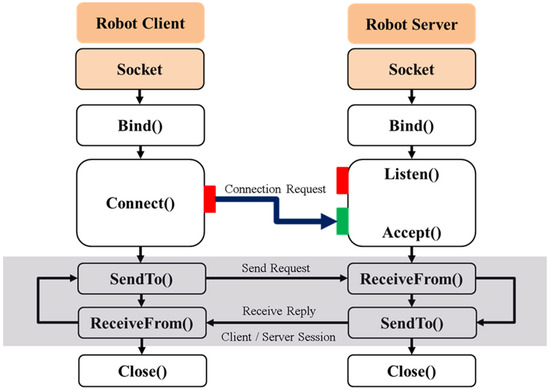
Figure 4.
Multi-robot TCP/IP communication system between robot server and robot clients.
TCP/IP communication model provides a connection-based protocol and includes all the algorithms necessary for opening multiple connections, ensuring error-free data transfer over the network, and then closing the connections. In the designed system, the server socket that is bound to a port number on the same computer and listens to the robot client’s incoming requests is an endpoint to provide a bidirectional communication link between the robot server and robot clients running on the same network. The robot client socket has to know the robot server’s IP address and port number. Once the connection is established between the robot server and the robot client, they can communicate through their sockets for sending and receiving messages. After the connection is established between the robot server and the robot client, the robot server listens to the port to check if any robot client request exists. The robot client sends a message containing its spatio-temporal (UtmX, UtmY, speed, and heading) data. Every robot client connecting to the robot server should be sent this message. When the robot server receives the messages from the robot clients, it collects all data, stores it to an array variable, creates a WiFi message frame, and transfers it to the robot clients via Wi-Fi (Figure 5). The size of the WiFi message frame is a maximum of 2346 bytes and the maximum length of the data field is 2312 bytes. In this study, both the robot server and the robot clients send a Wi-Fi message containing 33 bytes of data.
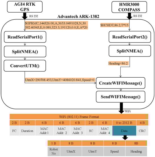
Figure 5.
Data transmission from the robot client to the robot server via WiFi.
2.3. Software Implementation of R2R Communication System
Client–server-based software was developed using C#.NET programming language in Microsoft Visual Studio 2015 platform to create the WiFi communication between the mobile robot server and the mobile robot clients. C# Multithreaded Socket Programming technique was used to communicate with more than one mobile robot client at the same time in the same network in developed software. The Microsoft.NET framework provides two namespaces: System.Net for providing the TCP/IP protocol and System.Net.Sockets for providing the socket class to send and receive data over the network. In multithreaded socket programming, the mobile robot server receives a connection request from the mobile robot client side; the mobile robot server creates a separate mobile robot client thread on the mobile robot server side to communicate with that particular mobile robot client socket. That means the mobile robot client can communicate independently with their mobile robot client thread on the mobile robot server side.
The steps involved in establishing a multithreaded TCP/IP socket on the mobile robot server side are as follows:
- Create a mobile robot server socket with the private static readonly Socket serverSocket = new Socket (AddressFamily.InterNetwork, SocketType.Stream, ProtocolType.Tcp) method.
- Bind the socket to an address using the serverSocket.Bind (new IPEndPoint (IPAddress.Any, PORT)) method.
- Listen for connections with the serverSocket.Listen(0) method.
- Accept a connection with the serverSocket.BeginAccept (AcceptCallback, null) method.
- Send and receive data with the Socket current = (Socket)AR.AsyncState object.
- Close all connections with the serverSocket.Close() method.
The steps for establishing a multithreaded TCP/IP socket on the mobile robot client side are the following:
- Create a mobile robot client socket using the private static readonly Socket ClientSocket = new Socket (AddressFamily.InterNetwork, SocketType.Stream, ProtocolType.Tcp) method.
- Connect the socket to the address of the mobile robot server using the ClientSocket.Connect (IPAddress.Loopback, PORT) method.
- Send data using the ClientSocket.Send (buffer, 0, buffer.Length, SocketFlags.None) method.
- Receive data using the ClientSocket.Receive (buffer, SocketFlags.None) method.
- Close the connection using the ClientSocket.Close() method.
Figure 6 shows the screenshot of the graphical user interface of the R2R wireless communication software. There are two radio buttons in the software window named “Server” and “Client” If “Server” is selected, the mobile robot works as a mobile robot server, or “Client” is selected, and the mobile robot works as a mobile robot client.
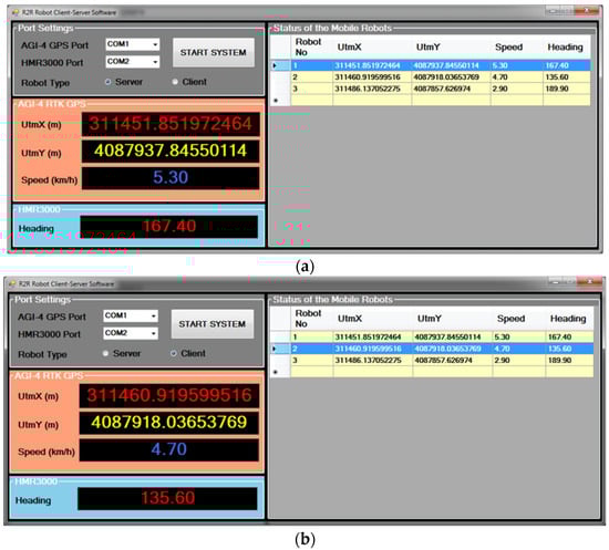
Figure 6.
Graphic user interfaces of the R2R wireless communication software: (a) mobile robot server side and; (b) mobile robot client side.
2.4. Collision Avoidance Algorithm
Four-wheel differential-drive mobile robots use a simple drive mechanism that provides differential speed difference between the right and left wheels. Wheels on both sides of the mobile robot can be independently driven in either a forward or reverse direction. It is assumed that no slip happens between the mobile robot’s wheels and the ground during motion. A schematic illustration of a four-wheel differential-drive mobile robot is shown in Figure 7. The coordinates of points (X1, Y1) define the position of the GPS receiver of the mobile robot in a global frame. In the figure, L is the length of the robot and W is the width.
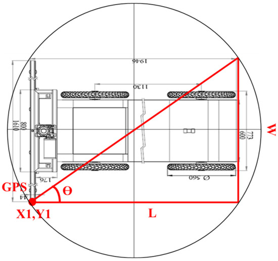
Figure 7.
Schematic illustration of the metrics of a differential-drive mobile robot.
In the proposed collision–avoidance algorithm, it is assumed that all mobile robots move from the source point (X1, Y1) to the target point following a straight line. The main idea of the proposed algorithm is illustrated by taking into account the case in which two mobile robots lie in a trajectory that will lead them to collide. The mathematical operations in the proposed algorithm are based on the condition that the mobile robots moving 180 degrees opposite each other would pass tangential to each other (Figure 8).
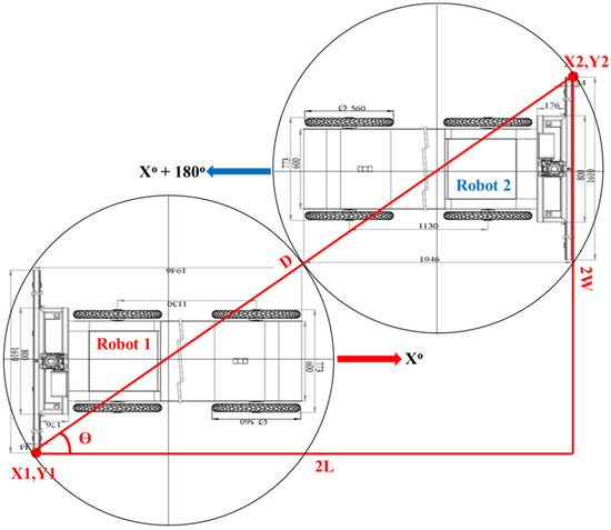
Figure 8.
Illustration of the condition that the mobile robots moving 180 degrees opposite each other would pass tangentially to each other.
The situation shown in Figure 8 is used to calculate the optimum reference distance and angle values to be used in the collision avoidance algorithm. The calculation of optimum reference distance (DRef) and angle () values are performed using the following equations:
where L represents the length of the mobile robot, W is the width of the mobile robot, and D is the longest side of the mobile robot. Mobile robots moving in the field instantly monitor the position and heading angle data of the other mobile robots via the developed R2R communication system. Within the R2R communication system, the real distances (D) and heading angles (tan θ) of all mobile robots to each other are instantly calculated. The calculation of real distance and heading angle values are performed using the following equations:
In the proposed collision avoidance algorithm, when the D = DRef condition is met for two mobile robots coming at 180 degrees relative to each other, the mobile robots are stopped. Meanwhile, the tangent angles of the robots are calculated. If the tan θ angle is greater than or equal to the angle, the mobile robots continue to drive without collision. On the other hand, if the tan θ angle is smaller than the angle, the collision avoidance system is activated. In the collision avoidance system, all mobile robots moving in the field have mobile robot numbers from 1 to N. The basic rule in the proposed algorithm is the definition of the pass priority. Priority pass is a system that defines that the mobile robot with the lower mobile robot number than the two mobile robots in the reference boundaries has to pass superiority. In the case shown in Figure 8, Robot 1 has a pass priority over Robot 2. The schematic illustration of the collision avoidance system is given in Figure 9.
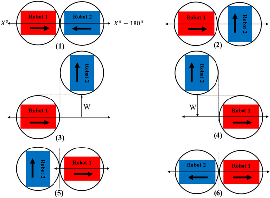
Figure 9.
A step-by-step schematic illustration of the collision avoidance system (1) Step 1 (2) Step 2 (3) Step 3 (4) Step 4 (5) Step 5 (6) Step 6.
The algorithm of the collision avoidance system consists of the following steps:
Step 1. Calculation of the actual values of the variables: GPS coordinates of Robot 1 and Robot 2 ((X1, Y1), (X2, Y2)), heading angles of Robot 1 and Robot 2 (θ1, θ2), the optimum reference distance (DRef) and angle (), the real distances (D) and heading angles (tan θ). Further inputs are the following constants: length of the robots (L), width of the robots (W).
Step 2. When the D = DRef and the tan θ angle is smaller than the angle, both robots stop in their position. If the tan θ is negative, Robot 2 turns 90 degrees to the left in its current position. If the tan θ is positive, Robot 2 turns 90 degrees to the right at its current position.
Step 3. The Robot 2 moves forward by the distance equal to W. Afterwards, the Robot 1 continues its movement in its direction of movement.
Step 4. When the D = DRef, Robot 2 moves back by the distance equal to W.
Step 5. After Robot 2 moves back by a distance equal to W, it stops.
Step 6. Finally, Robot 2 turns left or right according to its target direction of movement. And, both robots move towards their target points without collision.
3. Results and Discussions
This work is focused on the wireless R2R communication mechanism and the collision avoidance algorithm for multi-robot applications in precision farming. The development of modern information technologies and wireless communication technologies are very important to provide connectivity for portable and mobile precision farming applications. And the development of autonomous mobile robots is continuously gaining importance for repetitive agricultural tasks in the agricultural domain. One aspect often neglected during the development of autonomous mobile robots is the communication of the multiple robots working in the same agricultural field. In this paper, a wireless R2R communication system between mobile robots was proposed to solve this aspect. The experimental wireless network contains a mobile robot server and more than one mobile robot client. The proposed mobile robot server reads the spatio-temporal data, which are sent from all the mobile client robots. It stores all the data in an array, creates the WiFi message frame, and sends it to the mobile robot clients. Figure 10 shows an algorithm for collecting and merging the spatio-temporal data of the mobile robot clients with the help of developed software.
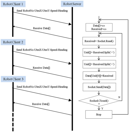
Figure 10.
Algorithm for collecting and merging the WiFi message frame.
The Split() method, which is used to split a string based on the delimiters passed to the string, is part of the string class in C#. The Split() method returns an array of string (Unit[]) generated by splitting the original string separated by the “-” delimiter passed as a parameter in the Split() method. All data from mobile robot clients splits and moves to an array (Data[]) according to robot numbers. As soon as a message is received from any mobile robot client, the algorithm is run and the array containing the data of all mobile robot clients in the network is sent to the relevant mobile robot client.
The maximum length of the data field in a Wi-Fi message frame is 2312 bytes. The spatio-temporal data were sent as 33 bytes of data in this study. This means that the wireless R2R communication system is capable of supporting a maximum of 70 mobile robots per wireless network. The number of supported mobile robots seems to be satisfactory for precision farming applications. In a developed wireless R2R communication system, every mobile robot is capable of working as a mobile robot server or a mobile robot client.
Nowadays, with the increase in the number of mobile robots in farming applications, communication and coordination between robots are necessary to fulfill complex agricultural tasks. Communication plays an important role in the performance of multi-robot systems, where the robots interact with each other to exchange their spatio-temporal data and collected sensor data. In the developed wireless R2R communication system, the Wi-Fi message frame contains 33 bytes of spatio-temporal data (UtmX, UtmY, Speed, and Heading) of the mobile robots. On the other hand, this system is also capable of sending other sensor data within the remaining 2279 bytes in the data section of the Wi-Fi message frame.
The multi-robots in farm areas need to adjust their locations in real time. For this reason, the data exchange of communication among multiple robots is mainly focused on wireless communication technology. This technology mainly involves a wireless local or personal area network such as Wi-Fi, Bluetooth, ZigBee, and IRDA (infrared data association). Among them, Wi-Fi technology has been mostly preferred in agricultural multi-robots [31]. When these three wireless communication technologies are compared, Wi-Fi technology has been used in our study due to its features such as fast transmission speed, long effective distance, reliable connection, and wide coverage.
To evaluate the effectiveness and usefulness of the R2R communication and multi-robot collision system for multi-robot systems, the developed communication system and the algorithm were tested in the field. It evaluated three different cases for validating the collision avoidance algorithm in the field experiment. Firstly, the case of the real distance and the calculated distance are equal, and the real angle is greater than or equal to the calculated angle was tested (Figure 11). Secondly, the case of the positive of the calculated real tangent angle was tested (Figure 12). Lastly, the case of the negative of the calculated real tangent angle was tested (Figure 13).
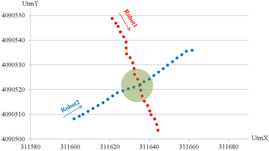
Figure 11.
Test result for case 1.
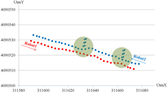
Figure 12.
Test result for case 2.
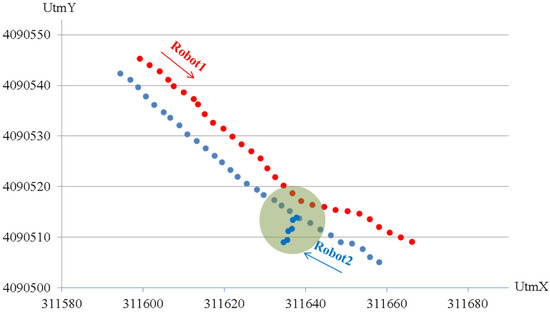
Figure 13.
Test result for case 3.
Figure 11 shows the test result for collision avoidance in the case of the real distance and the calculated distance being equal and the real angle is greater than or equal to the calculated angle. Robot 1 has a passing priority due to its low robot number. Robot 1 moves with a heading angle of approximately 170 degrees. On the other hand, Robot 2 moves at an angle of about 50 degrees. When the robots reach the collision boundary, Robot 2 stops and Robot 1 moves forward. After Robot 1 is out of the collision boundary, Robot 2 resumes its movement.
Figure 12 shows the test result for collision avoidance in the case of the positive of the calculated real tangent angle. Robot 1 moves with a heading angle of approximately 290 degrees. On the other hand, Robot 2 moves at an angle of about 110 degrees. When the robots reach the collision boundary, the robots stop, and Robot 2 starts the collision avoidance maneuver. Robot 2 turns 90 degrees right and moves forward as far as its width; Robot 1 continues to move forward. After Robot 1 moves out of the collision boundary, Robot 2 moves back by its width and turns 90 degrees to the left. Then, Robot 2 continues to move in its direction.
Figure 13 shows the test result for collision avoidance in the case of the negative of the calculated real tangent angle. Robot 1 moves with a heading angle of approximately 130 degrees. On the other hand, Robot 2 moves at an angle of about 310 degrees. When the robots reach the collision boundary, the robots stop, and Robot 2 starts the collision avoidance maneuver. Robot 2 turns 90 degrees left and moves forward as far as its width; Robot 1 continues to move forward. After Robot 1 moves out of the collision boundary, Robot 2 moves back by its width and turns 90 degrees to the right. Then, Robot 2 continues to move in its direction.
Several algorithms for multi-robot collision avoidance have been proposed over the last few decades. These are potential fields [32], the dynamic window [33] inevitable collision states [34], sequential convex programming [35], model predictive control [36], priority-based planning [37], social forces [38], buffered Voronoi cells [39], barrier certificates [40], reciprocal velocity obstacle (RVO) [41], optimal reciprocal collision-avoidance (ORCA) [42], reciprocal orientation algorithm (ROA) [43], and shortest distance algorithm (SDA) [44]. However, none of the algorithms have been supported by a robot-to-robot communication system. In this paper, a new algorithm is suggested to solve the problem of multi-robot collision avoidance. The main idea of the study is to define the transition priority for the robots and to start the maneuver for collision avoidance from the two encountering robots to the one that does not have the transition priority. In this way, it is ensured that the robots for agricultural applications continue their work without leaving the route they should follow. The basis of the developed algorithm is formed by the developed robot-to-robot communication system. When the studies in the literature are evaluated, it is seen that this study is important in terms of communication between ground-based mobile robots. In addition, the collision algorithm is unique in the software prioritization of robots.
4. Conclusions
One key element in multi-robot systems is communicating between robots and providing coordination to achieve well-defined agricultural tasks. The aim of the wireless R2R communication system was based on a client–server model where clients send the spatio-temporal data to the server and the server sends all collected robot data to all robots in a wireless network. The designed wireless R2R communication system is suitable for providing wireless connectivity between the devices which is capable of Wi-Fi communication not only on mobile platforms but also on stationary systems for precision farming applications. This system provides a flexible, reliable, adaptable, and elegant solution to connect all mobile systems in agriculture. In conclusion, the wireless R2R communication system can be used safely in both outdoor and indoor conditions for agricultural mobile systems. In this study, a new and robust collision–avoidance algorithm was introduced for multi-robot systems. This algorithm is based on the kinematics of the robot and robot-to-robot communication system. From the test results, we found that the algorithm is collision-free and straightforward. We believe that the R2R communication system and collision–avoidance algorithm are well suited for real-time computation and sensing thanks to its low computational complexity, which allows for agricultural multi-robot systems. Future work should focus on the multi-robot spraying, fertilizing, and harvesting applications using the proposed R2R communication system and algorithm.
Author Contributions
Conceptualization, İ.Ü.; methodology, İ.Ü. and Ö.K.; software, O.E.; validation, İ.Ü. and O.E.; formal analysis, Ö.K. and G.M.; investigation, İ.Ü., Ö.K. and O.E.; resources, G.M.; data curation, O.E.; writing—original draft preparation, İ.Ü.; writing—review and editing, İ.Ü. and G.M.; visualization, G.M. and Ö.K.; supervision, İ.Ü. and Ö.K.; funding acquisition, G.M. All authors have read and agreed to the published version of the manuscript.
Funding
The APC was funded by the University Politehnica of Bucharest, Romania, within the PubArt Program.
Institutional Review Board Statement
Not applicable.
Informed Consent Statement
Not applicable.
Data Availability Statement
Not applicable.
Conflicts of Interest
The authors declare no conflict of interest.
References
- Lin, H.B.; Yi, C.J.; Liu, Z.M. Experimental Study on Quadruped Wheel Robot for Wheat Precision Seeding. Key Eng. Mater. 2016, 693, 1651–1657. [Google Scholar] [CrossRef]
- Bakker, T.; Asselt, K.; Bontsema, J.; Müller, J.; van Straten, G. Systematic design of an autonomous platform for robotic weeding. J. Terramechanics 2010, 47, 63–73. [Google Scholar] [CrossRef]
- Lili, W.; Bo, Z.; Jinwei, F.; Xiaoan, H.; Shu, W.; Yashuo, L.; Qiangbing, Z.; Chongfeng, W.; Zhou, Q. Development of a tomato harvesting robot used in greenhouse. Int. J. Agric. Biol. Eng. 2017, 10, 140–149. [Google Scholar] [CrossRef]
- Cantelli, L.; Bonaccorso, F.; Longo, D.; Melita, C.D.; Schillaci, G.; Muscato, G. A Small Versatile Electrical Robot for Autonomous Spraying in Agriculture. Agriengineering 2019, 1, 391–402. [Google Scholar] [CrossRef]
- Vakilian, K.A.; Massah, J. A farmer-assistant robot for nitrogen fertilizing management of greenhouse crops. Comput. Electron. Agric. 2017, 139, 153–163. [Google Scholar] [CrossRef]
- MarketsandMarkets. Agricultural Robots Market by Type (Milking Robots, UAVs/Drones, Automated Harvesting Systems, Driverless Tractors), Farm Produce, Farming Environment (Indoor, Outdoor), Application, and Geography—Global Forecast to 2026. Available online: https://www.marketsandmarkets.com/Market-Reports/agricultural-robot-market-173601759.html. (accessed on 4 February 2022).
- Shamshiri, R.R.; Weltzien, C.; Hameed, I.A.; Yule, I.J.; Grift, T.E.; Balasundram, S.K.; Pitonakova, L.; Ahmad, D.; Chowdhary, G. Research and development in agricultural robotics: A perspective of digital farming. Int. J. Agric. Biol. Eng. 2018, 11, 1–14. [Google Scholar] [CrossRef]
- Cheen, F.A.; Caraelli, R. Agricultural robotics: Unmanned robotic service units in agricultural tasks. IEEE Ind. Electron. Mag. 2013, 7, 48–58. [Google Scholar] [CrossRef]
- Bechar, A.; Vigneault, C. Agricultural robots for field operations: Concepts and components. Biosyst. Eng. 2016, 149, 94–111. [Google Scholar] [CrossRef]
- Zhang, C.; Noguchi, N.; Yang, L. Leader–follower system using two robot tractors to improve work efficiency. Comput. Electron. Agric. 2016, 121, 269–281. [Google Scholar] [CrossRef]
- Parker, L.E.; Rus, D.; Sukhatme, G.S. Multiple Mobile Robot Systems. In Springer Handbook of Robotics; Siciliano, B., Khatib, O., Eds.; Springer Handbooks; Springer: Cham, Switzerland, 2016; pp. 1335–1385. [Google Scholar]
- Noguchi, N.; Oscar, C.; Barawid, O.C., Jr. Robot Farming System Using Multiple Robot Tractors in Japan Agriculture. IFAC Proc. Vol. 2011, 44, 633–637. [Google Scholar] [CrossRef]
- Roldan, J.J.; del Cerro, J.; Garzon-Ramos, D.; Garcia-Aunon, P.; Garzon, M.; de Leon, J.; Barrientos, A. Robots in agriculture: State of art and practical experiences. In Service Robots; Neves, A.J.R., Ed.; IntechOpen: London, UK, 2018; pp. 67–90. [Google Scholar]
- RHEA. Robot Fleets for Highly Effective Agriculture and Forestry Management. Available online: https://cordis.europa.eu/project/id/245986. (accessed on 4 February 2022).
- Pérez-Ruiz, M.; Gonzalez-De-Santos, P.; Ribeiro, A.; Fernandez-Quintanilla, C.; Peruzzi, A.; Vieri, M.; Tomic, S.; Agüera, J. Highlights and preliminary results for autonomous crop protection. Comput. Electron. Agric. 2015, 110, 150–161. [Google Scholar] [CrossRef]
- Emmi, L.; Gonzalez-De-Soto, M.; Pajares, G.; Gonzalez-De-Santos, P. New Trends in Robotics for Agriculture: Integration and Assessment of a Real Fleet of Robots. Sci. World J. 2014, 2014, 404059. [Google Scholar] [CrossRef]
- Conesa-Muñoz, J.; Gonzalez-De-Soto, M.; Gonzalez-De-Santos, P.; Ribeiro, A. Distributed Multi-Level Supervision to Effectively Monitor the Operations of a Fleet of Autonomous Vehicles in Agricultural Tasks. Sensors 2015, 15, 5402–5428. [Google Scholar] [CrossRef]
- Gonzalez-De-Santos, P.; Ribeiro, A.; Fernandez-Quintanilla, C.; Lopez-Granados, F.; Brandstoetter, M.; Tomic, S.; Pedrazzi, S.; Peruzzi, A.; Pajares, G.; Kaplanis, G.; et al. Fleets of robots for environmentally-safe pest control in agriculture. Precis. Agric. 2017, 18, 574–614. [Google Scholar] [CrossRef]
- Idbella, M.; Iadaresta, M.; Gagliarde, G.; Mennella, A.; Mazzoleni, S.; Bonanomi, G. AgriLogger: A New Wireless Sensor for Monitoring Agrometeorological Data in Areas Lacking Communication Networks. Sensors 2020, 20, 1589. [Google Scholar] [CrossRef]
- Ünal, İ. Integration of ZigBee based GPS receiver to CAN network for precision farming applications. Peer Peer Netw. Appl. 2020, 13, 1394–1405. [Google Scholar] [CrossRef]
- Gsangaya, K.R.; Hajjaj SS, H.; Sultan MT, H.; Hua, L.S. Portable, wireless, and effective internet of things-based sensors for precision agriculture. Int. J. Environ. Sci. Tech. 2020, 17, 3901–3916. [Google Scholar] [CrossRef]
- Amer, G.; Mudassir, S.M.M.; Malik, M.A. Design and operation of Wi-Fi agribot integrated system. In Proceedings of the 2015 International Conference on Industrial Instrumentation and Control, Pune, India, 28–30 May 2015; pp. 207–212. [Google Scholar]
- Jian-Sheng, P. An Intelligent Robot System for Spraying Pesticides. Open Electr. Electron. Eng. J. 2014, 8, 435–444. [Google Scholar] [CrossRef]
- Brinkhoff, J.; Hornbuckle, J.; Quayle, W.; Lurbe, C.B.; Dowling, T. WiField, an IEEE 802.11-based agricultural sensor data gathering and logging platform. In Proceedings of the 2011 Eleventh International Conference on Sensing Technology (ICST), Sydney, NSW, Australia, 4–6 December 2017; pp. 1–6. [Google Scholar]
- Zant, C.E.; Klement, N.; Bettayeb, B.; Sahnoun, M.; Havard, V. UV-Robot supervision system design and development. In Proceedings of the 25ème Colloque des Sciences de la Conception et de l’Innovation, Budapest, Hungary, 5–6 July 2018; pp. 1–10. [Google Scholar]
- Pretto, A.; Aravecchia, S.; Burgard, W.; Chebrolu, N.; Dornhege, C.; Falck, T.; Fleckenstein, F.V.; Fontenla, A.; Imperoli, M.; Khanna, R.; et al. Building an Aerial–Ground Robotics System for Precision Farming: An Adaptable Solution. IEEE Robot. Autom. Mag. 2020, 28, 29–49. [Google Scholar] [CrossRef]
- Lijina, P.; Nippun, K.A. Bluetooth RSSI based collision avoidance in multirobot environment. In Proceedings of the International Conference on Advances in Computing, Communications and Informatics, Jaipur, India, 21–24 September 2016; pp. 2168–2174. [Google Scholar] [CrossRef]
- Hou, Y.C.; Mohamed Sahari, K.S.; Weng, L.Y.; Foo, H.K.; Abd Rahman, N.A.; Atikah, N.A.; Homod, R.Z. Development of collision avoidance system for multiple autonomous mobile robots. Int. J. Adv. Robot. Syst. 2020, 17, 1–15. [Google Scholar] [CrossRef]
- Ünal, İ.; Kabaş, Ö.; Sözer, S. Real-Time Electrical Resistivity Measurement and Mapping Platform of the Soils with an Autonomous Robot for Precision Farming Applications. Sensors 2020, 20, 251. [Google Scholar] [CrossRef] [PubMed]
- Sharma, P.; Singh, G. Comparison of Wi-Fi IEEE 802.11 Standards Relating to Media Access Control Protocols. Int. J. Comput. Sci. Inf. Secur. 2016, 14, 856–862. [Google Scholar]
- Mao, W.; Liu, Z.; Liu, H.; Yang, F.; Wang, M. Research Progress on Synergistic Technologies of Agricultural Multi-Robots. Appl. Sci. 2021, 11, 1448. [Google Scholar] [CrossRef]
- Khatib, O. Real-time obstacle avoidance for manipulators and mobile robots. Int. J. Robot. Res. 1986, 5, 90–98. [Google Scholar] [CrossRef]
- Brock, O.; Khatib, O. High-speed navigation using the global dynamic window approach. In Proceedings of the 1999 IEEE International Conference on Robotics and Automation, Detroit, MI, USA, 10–15 May 1999; pp. 341–346. [Google Scholar]
- Petti, S.; Fraichard, T. Safe motion planning in dynamic environments. In Proceedings of the IEEE/RSJ International Conference on Intelligent Robots and Systems, Edmonton, AB, Canada, 2–6 August 2005; pp. 2210–2215. [Google Scholar]
- Schulman, J.; Duan, Y.; Ho, J.; Lee, A.; Awwal, I.; Bradlow, H.; Pan, J.; Patil, S.; Goldberg, K.; Abbeel, P. Motion planning with sequential convex optimization and convex collision checking. Int. J. Robot. Res. 2014, 33, 1251–1270. [Google Scholar] [CrossRef]
- Morgan, D.; Chung, S.-J.; Hadaegh, F.Y. Model Predictive Control of Swarms of Spacecraft Using Sequential Convex Programming. J. Guid. Control. Dyn. 2014, 37, 1725–1740. [Google Scholar] [CrossRef]
- Cap, M.; Novak, P.; Kleiner, A.; Selecky, M. Prioritized Planning Algorithms for Trajectory Coordination of Multiple Mobile Robots. IEEE Trans. Autom. Sci. Eng. 2015, 12, 835–849. [Google Scholar] [CrossRef]
- Ferrer, G.; Garrell, A.; Sanfeliu, A. Robot companion: A social-force based approach with human awareness-navigation in crowded environments. In Proceedings of the 2013 IEEE/RSJ International Conference on Intelligent Robots and Systems, Tokyo, Japan, 3–7 November 2013; pp. 1688–1694. [Google Scholar]
- Zhou, D.; Wang, Z.; Bandyopadhyay, S.; Schwager, M. Fast, On-line Collision Avoidance for Dynamic Vehicles Using Buffered Voronoi Cells. IEEE Robot. Autom. Lett. 2017, 2, 1047–1054. [Google Scholar] [CrossRef]
- Wang, L.; Ames, A.D.; Egerstedt, M. Safety Barrier Certificates for Collisions-Free Multirobot Systems. IEEE Trans. Robot. 2017, 33, 661–674. [Google Scholar] [CrossRef]
- Van den Berg, J.; Lin, M.; Manocha, D. Reciprocal velocity obstacles for real-time multi-agent navigation. In Proceedings of the 2008 IEEE International Conference on Robotics and Automation, Pasadena, CA, USA, 19–23 May 2008; pp. 1928–1935. [Google Scholar]
- Van den Berg, J.; Guy, S.J.; Lin, M.; Manocha, D. Reciprocal n-body Collision Avoidance. In Proceedings of the 14th International Symposium of Robotic Research, Lucerne, Switzerland, 31 August–3 September 2009; pp. 3–19. [Google Scholar]
- Rashid, A.; Ali, A.A.; Frasca, M.; Fortuna, L. Multi-robot collision-free navigation based on reciprocal orientation. Robot. Auton. Syst. 2012, 60, 1221–1230. [Google Scholar] [CrossRef]
- Ali, A.A.; Rashid, A.T.; Frasca, M.; Fortuna, L. An algorithm for multi-robot collision-free navigation based on shortest distance. Robot. Auton. Syst. 2016, 75, 119–128. [Google Scholar] [CrossRef]


Disclaimer/Publisher’s Note: The statements, opinions and data contained in all publications are solely those of the individual author(s) and contributor(s) and not of MDPI and/or the editor(s). MDPI and/or the editor(s) disclaim responsibility for any injury to people or property resulting from any ideas, methods, instructions or products referred to in the content. |
© 2023 by the authors. Licensee MDPI, Basel, Switzerland. This article is an open access article distributed under the terms and conditions of the Creative Commons Attribution (CC BY) license (https://creativecommons.org/licenses/by/4.0/).