Article

Distributed Weighted Coverage for Multi-Robot Systems in Non-Convex Environment

1
School of Mechatronic Engineering, Xi’an Technological University, Xi’an 710021, China
2
School of Electronic Information Engineering, Xi’an Technological University, Xi’an 710021, China
3
MESA-Laboratory, School of Engineering, University of California, Merced, CA 95343, USA
*
Author to whom correspondence should be addressed.
Appl. Sci. 2023, 13(14), 8530; https://doi.org/10.3390/app13148530
Submission received: 28 June 2023 / Revised: 17 July 2023 / Accepted: 20 July 2023 / Published: 24 July 2023
(This article belongs to the Section Robotics and Automation)

Abstract

:
Multi-robot coverage systems are widely used in operations such as environmental monitoring, disaster rescue, and pollution prevention. This study considers inherent positioning errors in positioning systems and ground mobile robots with limited communication distance and poor quality in practice. A centroidal Voronoi tessellation algorithm-based formation control technology for multi-robots is optimized. First, by constructing buffered Voronoi cells (BUVCs) for each robot, the collision avoidance ability of the multi-robot formation movement is improved. Next, the formation control problem of multi-robots in a limited communication range and non-convex environment is realized via discrete Voronoi partitioning, a communication distance constraint, and an obstacle avoidance strategy. Simulation and experiment results demonstrate that the proposed method can effectively solve the position generation problem of multi-robot coverage systems in a non-convex environment with actual sizes of the robots and positioning system errors and can further improve the collision avoidance performance of robots and the robustness of BUVC algorithms.

1. Introduction

Swarm robots are composed of simple single agents, which have certain autonomous, local communication, and perception abilities. By imposing some simple rules, the entire system exhibits complex group behavior characteristics, such as self-organization and cooperation [1]. Swarm robots are inspired by many biological species in nature that exhibit collective behaviors [2,3]. Technological advances and cost reductions in communication, computing, control, and sensing devices for intelligence, as well as the advantages of multi-intelligent body systems over single intelligence, collaborative control of multi-agent systems, and mobile sensor networks, have attracted considerable attention in recent years. Particularly, a group of agents is deployed to desired locations according to different task scenarios and requirements. The execution of different tasks in the same environment is the principal application scenario in collaborative multi-agent systems. However, based on different scenarios, these distributed tasks may vary. Some examples of distributed tasks include forest fire monitoring and detection [4,5,6], environmental monitoring [7,8], pollution source monitoring and control [9,10], and environmental coverage [11,12]. However, multi-robot systems are also robust and scalable for area coverage.
Ref. [13] proposed an overlay control law that moves each mobile sensor to the centroid of its Voronoi cell. Ref. [14] solved the problem of distribution neutralization during the two-dimensional diffusion of toxic substances by a distributed agent control method, where the location of the agent is optimized by centroidal Voronoi tessellation (CVT). Cortes et al. [15] introduced distributed control laws using non-smooth analysis and computational geometry, which have applications in network robot coordination problems. Thomas Chevet [16] drove a multi-intelligent system into a static Chebyshev structure by proposing a new chance-constrained model predictive control algorithm-based on-state estimation, where each agent is located at the Chebyshev center of its Voronoi cell, and the noise problem in the system model is effectively solved. Ref. [17] proposed a distributed control scheme for the coverage of Voronoi-based discrete-time multi-agent dynamic systems in a multi-dimensional static convex polyhedron environment. By using a local control law to steer each robot toward the Chebyshev center of its associated time-varying Voronoi neighborhood, the mechanism by which subsets of robots agree on intra-neighbor distances was revealed. Distributed coordination algorithms for increasing the coverage sensing range of non-identical mobile sensor networks are provided in Refs. [18,19]. In [20], an algorithm was developed to maximize the contribution of each mobile robot to the overall coverage by adding several mobile sensors to a static sensor network and positioning them appropriately in the required field.
Although the abovementioned studies and related contributions can enhance the effective application of multi-robots for environmental coverage, they are all based on some hypothetical premises. These include the assumption that the robots can communicate mutually, they operate in an obstacle-free environment, and factors such as localization errors and robots’ sizes in real systems are negligible. For covering problems in non-convex environments, Carlos [21] and Xiaotian [22] mapped a class of connected regions in non-convex environments to convex regions via a diffeomorphism. By combining with the Lloyd algorithm, the coverage problem in a simple non-convex environment can effectively be solved. However, this method has limitations in covering problems with multiple obstacles or complex non-convex environments. Nair [23] replaced the traditional Euclidean distance with the geodesic distance. However, the collision avoidance performance of this method in complex environments is not reflected. Moreover, obstacles have significant implications on the robot’s trajectory. Thus, the algorithm convergence is slow. Finally, because the calculation of the geodesic distance is expensive, the robot can fall to extreme points because of obstacles. To address robot collision problems that may occur within the geodesic distance, Andreas [24] combined the classical Lloyd algorithm with the local path planning TangentBug to calculate robotic motion near obstacles and corners based on the definition of geodesic distance. In addition, the concept of a virtual generator is proposed to address centroid unreachability problems to map the centroids of accessible regions. The convergence and optimality of the algorithm are validated. Lu [25] and Mahboubi [26] proposed a visibility-based definition of a Voronoi diagram based on the decay of sensor capabilities due to boundaries or obstacles. This definition extends the continuous-time Lloyd method for convex domains and modifies the conditions related to the visibility of Voronoi boundaries. Lu used the projection of a centroid to solve problems wherein centroids are not located in Voronoi cells and introduced smoothness constraints during deployment of robots to avoid accidents at sharp turns. As can be observed in the aforementioned contributions on non-convexity, algorithms with simple CVTs, CVTs and the combination of a differential homogeneous embryo, geodesic lines, and artificial potential fields cannot be easily adapted to complex environments but can only adapt to the cluster controls in simpler environments with poor stabilities. Moreover, a greater computational effort is required to adapt algorithms containing geodesic lines and differential homogeneous embryos to non-convex regions.
Robots with different capabilities are applied in search and rescue, patrol, surveillance, and other fields. The control problem of multi-robots with different capabilities has been an important topic in robot research. In addition, the uncertainty of the sensors used in robot positioning also increases the concern about the problem of imprecise positioning. Alyssa [27] aimed to adapt a group of robots to study the performance changes among different robots while enabling them to complete collaborative tasks online. He proposed a distributed approach to the online learning of the relative performance changes among robots and automatically compensated the learning approach by assigning smaller environment shares to weaker robots and larger environment shares to stronger robots. Based on this, the algorithm proposed by Mert [28] uses an energy-saving coverage optimal control scheme and a Hopfield neural network to create a power Voronoi diagram. The weights of each agent are calculated according to the different driver performances to independently achieve the optimal coverage configuration. Sotitis [29,30] aimed at the area coverage problem of mobile robot networks with inaccurate agent positioning. The convex space was divided according to the guaranteed Voronoi (GV) principle, and the responsibility area of each robot corresponded to its GV cell, bounded by hyperbolic arcs. The scheme based on gradient rise was used for area coverage and guarantees the Voronoi tessellation of the monitored area.
In this study, an effective multi-robot coverage control method is developed to coordinate a group of mobile robots to effectively cover the region of interest in the environment at a minimum cost. Primarily aiming at solving the inherent positioning error problem in a positioning system and the inability of a robot to be mass-pointed, this study introduces the positioning uncertainty factor and robot radius. This can buffer uncertainty Voronoi cells for robot construction and create larger cells for robots with large positioning uncertainties, while the introduction of buffer strips ensures that robots close to Voronoi boundaries do not collide. Subsequently, for a non-convex environment, both discrete and constrained Voronoi partitions are used to solve the non-convex limitations of CVTs. Therefore, considering that the communication ranges of the robots are generally limited [31], the communication distance constraint is used to solve the problem of inaccurate Voronoi partitioning and robot collision due to limited communication distance. By using multi-robot formations in a MATLAB simulation, we demonstrate that the proposed method can effectively solve the non-convex environment limited communication distance of robot localization in the uncertainty of a division, ensuring that each robot is in a safe area, even when the robot’s center is located at the edge of an adjacent BUVC. Thus, the collision avoidance performance and the robustness of a BUVC method in the process of multi-robot coverage are further improved.
The structure of the remainder of this article is as follows. In Section 2, the principle of a CVT and some problems occurring in practical applications are described. In Section 3, a BUVC partition with localization uncertainty and robot radius parameters is proposed to solve these problems. Thereafter, a constrained Voronoi partition and a communication distance constraint are proposed for a non-convex environment and the communication distance constraint, respectively. In Section 4, corresponding simulation results are presented to verify the effectiveness of the proposed algorithm. Section 5 and Section 6 present the distributed control strategy and numerical simulations employed in this study, respectively. Section 7 discusses the BUVC experiments using TurtleBot3 robots. Conclusions and future prospects are presented in Section 8.

2. Problem Statement

We suppose that n ground mobile robots p i with limited communication ranges are randomly distributed in a 2D convex region Q containing fixed obstacles. P = p 1 , p 2 , , p n represents the robots’ positions, and each robot has the same dynamic model and size with radius r. If the region Q is divided into convex polygon regions v i , each polygon contains only a single robot whose position is referred to as the generating point of the polygon, and the distance from any point in the polygon to the generating point is less than that to any other point in Q. If v i v j = ϕ , i j and { v i } i = 1 n = Q , the Voronoi partition of the region is generated, where the generating point p i corresponds to the Voronoi cell v i , and the partition structure is called the Voronoi diagram. The Voronoi partition v i generated by the robot p i can be described by the equation:
v i = { x Q q p i 2 < q p j 2 , i , j = 1 , 2 n , i j } .
where q is any observation point in Q, and | | · | | is the Euclidean distance between two points in Q. If the Voronoi cells of two robots share one edge, they are called neighbors, and the neighbors of robot p i are represented by N i .
Suppose that the coverage priority of different points in the region is specified by the region density function ρ ( q ) , and the function value in this function is non-negative. For the region point q that can be directly observed by the robot, the cost of monitoring the point by the robot is expressed in. For different robots, the function may be different. However, for any points with an equal distance to the same robot, the function is the same, that is q p i 2 = q p j 2 , q j , q k = Q .
Let a group of robots divide the task area into n areas, then place each agent in the appropriate position in the area, so that each point in the area is monitored by one robot. The cost function (the objective function to be optimized) for multiple robots to form the optimal configuration in the task area can be expressed as:
F ( P , V ) = i = 1 n q v i ρ ( q ) q p i 2 d q .
The CVT is a special case of a Voronoi partition. Suppose that in a given region, the density function in the environment region is ρ ( q ) ; the centroid of the Voronoi cell of the i-th robot can be obtained as
c v i = p v i q ρ ( q ) d q p v i ρ ( q ) d q , i = 1 , , n .
Where the density function ρ ( q ) refers to a distribution of interesting attributes in the environment. As the function value increases, the density value of an attribute increases. When the generating point of a Voronoi cell is the same as the centroid of the cell, it is called a centroid Voronoi tessellation. According to relevant convergence and stability proofs, when the robot moves to the centroid position, the cost function can be minimized, thus rendering the algorithm convergent and stable [32].
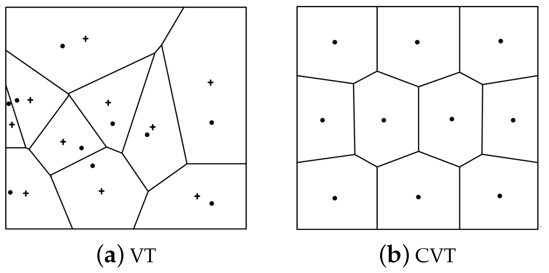
Figure 1a,b show the Voronoi tessellation and CVT, respectively. The “+” sign in Figure 1a represents the centroid c v i of the Voronoi cells, and the “.” sign and irregular multilaterals in Figure 1a,b represent the generating points and corresponding Voronoi cells, respectively.
When the position errors of the robots are zero, the robots’ sizes are negligible, no obstacles are found in the task area, and the robots can communicate mutually. If for the same point in a region, all the robots have the same detection cost, then the traditional CVT can provide the best division for the robots. However, when considering the abovementioned problems, the traditional CVT is no longer the best solution.

3. Buffer Uncertain Voronoi Cell (BUVC)

For a distributed multi-robot system operating in a task environment, a collision avoidance control strategy should be designed, especially for robots that cannot be presented as points. Although a CVT provides an obstacle avoidance attribute for robots, in practicality, they have real sizes. When the robots are simultaneously located at the edge of a Voronoi cell, a collision may occur, even if the robots’ centers are located in the cell. To solve the abovementioned problems, this study introduces the concept of a buffer zone and appropriately shrinks the edge of the original Voronoi cell so that the robots’ centers are located at the edge of the Voronoi cell and the robots do not collide with each other.
The traditional Voronoi cell boundary renders the robots i and j equidistant from their shared Voronoi edges. The buffer zone in this study adds weights based on the original equation, as follows:
v i b = { q Q p i q 2 p j q 2 ω i j } .
ω i j = ( r i + r j ) p i p j .
In Equation (5), ω i j is the cell weight value between robot i and its neighbor j, and r is the radius of the robot. Equations (4) and (5) create a gap between the boundaries of the Voronoi cells as a safe buffer zone to ensure that robots that are close to the edge of the cell do not collide.
Notably, each robot can measure its position through a positioning technology or communicate with its neighboring robots. However, owing to errors in the positioning system, the position of each robot cannot be accurately obtained. Therefore, in general, under laboratory conditions, each robot has different positioning uncertainties. Assuming that the upper bound of the positioning uncertainty of each robot R i u is known, to describe the positioning uncertainty, the positioning uncertainty factor λ i [ 0 , 1 ] is introduced to measure the positioning uncertainty (positioning error) of the robot. If λ i is close to 1, the radius of the robot’s positioning uncertainty is closer to the upper bound (that is, the positioning error is significant). On the contrary, the lower the robot’s positioning uncertainty, the smaller the positioning error.
ω i j = [ 1 + 1 2 ( λ i λ j ) ] ( r i + r j ) p i p j 1 2 ( λ i λ j ) p i p j 2 .
v i b , u = { q Q p i q 2 p j q 2 ω i j } .
When Equation (6) is changed to (5), both robots are located at the edge of their respective cells, and the distance between the two robots is d i j = ( r i + r j ) . In Equation (6), when ω i j increases, the Voronoi cell of the robot also increases.
v i b , u = { q Q p i q 2 p j q 2 = ω i j } .
According to hyperbolic theories, Equation (8) represents a single branch equation of a hyperbolic equation. The positions of the two robots are located at the focus points of the long axis. The parameter v i b , u may either be convex or non-convex because ω i j may either be positive or negative.
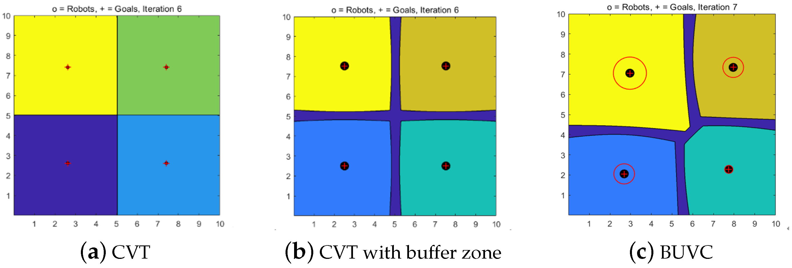
(a) When a buffer zone of a Voronoi cell and the positioning uncertainty of a robot are not considered, r = 0, λ i = 0, and ω i j = 0 . The distribution of the robots is governed by CVT, as shown in Figure 2a. The cell edge between the robots is located on the vertical line of the robot and is symmetrically distributed.
(b) When the buffer zone of the Voronoi cell is introduced, r i 0 , λ i =0, and ω i j = ( r i + r j ) p i p j . The distribution of the robots is shown in Figure 2b, wherein the black discs represent the actual robot sizes, and the buffer zone between the robots is located on the vertical bisector between the robots and is symmetrically distributed.
(c) When the buffer zone and the robots’ positioning uncertainties are introduced, r i 0 and λ i 0 , Equation (7) is obtained. The distribution of the BUVCs of multiple robots is shown in Figure 2c. The red circles represent the positioning uncertainties of the robots. The buffer zone between the robots tends to move toward the small side, demonstrating an asymmetric distribution.

4. BUVC under Limited Communication Distance in Non-Convex Environment

4.1. BUVC under Non-Convex Environment

Considering the limited communication distance in reality and the limitations of the non-convex environment of the traditional CVT, the task environment can be partitioned into convex and non-convex environments according to the geometry. A non-convex environment primarily refers to an environment with holes and large obstacles. Herein, the connection between any two points in an area is not blocked. For a strictly convex environment, based on the Lloyd algorithm, the controller can ensure that the robot asymptotically converges to the centroids of their respective Voronoi regions. However, this process is no longer applicable to an internal non-convex environment, as shown in Figure 3a, or an edge non-convex environment, as shown in Figure 3b. Therefore, for a non-convex task environment, the traditional CVT method needs to be improved.
First, BUVC division under a convex environment is performed for the non-convex environment Q R N containing a group of robots P = ( p 1 , p 2 , , p n ) . A group of divisions is obtained as follows:
V = { v i b , u } i = 1 n v i b , u = { q Q p i q 2 p j q 2 ω i j } .
Each robot computes all the discrete points within its designated region that satisfy the BUVC conditions, resulting in the partitioning of Voronoi cells.
Next, relevant information about the non-convex region O i can be obtained using moving robots. By constraining the non-convex region O i for division in the convex environment V, the BUVC division V o under the constraint of the non-convex environment can be obtained as follows:
V o = { v o , i b , u } i = 1 n v i b , u = { q Q p i q 2 p j q 2 ω i j } . v o , i b , u = v i b , u Q O
Figure 4 lists the division of the BUVC in three non-convex environments. The areas indicated by O in Figure 4a–c are holes, obstacles, and edge depressions, respectively. The small circle represents the robot, the colored area indicates the location of the robot in the Voronoi cell, and the red cross indicates the centroid of that area.

4.2. BUVC under Limited Communication Distance

Considering that the communication range of the robots in practice is limited rather than assuming that robots can communicate mutually in a given region as in the traditional CVT, the normal communication between a robot and its neighbors and the aforementioned discrete analog sensors is affected. Consequently, incorrect Voronoi regions may be developed around some robots, and the cost function may deteriorate. When the robots cannot move to the correct regional centroid, the cost function does not converge. Moreover, the robots may collide. A limited communication distance conforms to the characteristics of actual robots and reduces the communication and computing costs of the robots.
To solve the abovementioned problems after constructing the division V o of the BUVC under non-convex environment constraints, a limited communication distance is introduced. When calculating the points q Q contained in the Voronoi region of p i , only the satisfying analog sensors q and p i p j r c , i robots in p i are considered, where r c is the communication radius of each robot. The division V o of the BUVC under a limited communication distance can be obtained as follows:
V o = { v o , i b , u } i = 1 n v o , i b , u = { q Q , q Q O p i q r c , i 2 } . p i q 2 p j q 2 ω i j
The BUVC before and after introducing the limited communication range is shown in Figure 5. As shown in Figure 5b, after the constraint of the limited communication range is introduced, the Voronoi region of each robot is reduced, and its centroid is correspondingly shifted.
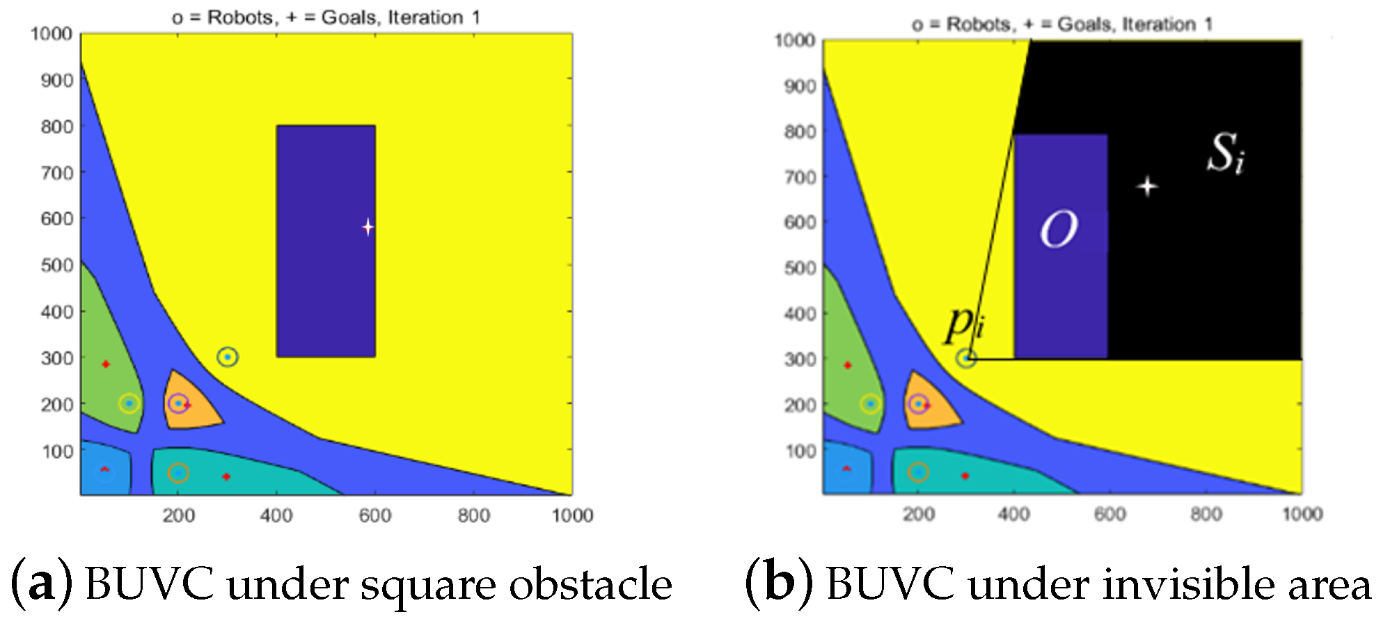
For several common centroid invisibility problems under BUVCs in non-convex environments during the division process, a centroid can be located in the invisible area relative to a robot, resulting in a collision with the non-convex part or the inability of the robot to reach the centroid. The concept of the invisible region S i , q , q Q is introduced as the region S i comprises all the relative and invisible points q corresponding to the robot p i in Q, as shown in Figure 6.
When the positions of the robots and their centroids are as shown in Figure 6, the robots can safely avoid obstacles and thus reach the final target by introducing the following obstacle avoidance strategies.
When the robot p i is in the safe area O + r i of the non-convex part O, and the centroid c v i of the Voronoi cell v o , j b , u of the robot is in the inaccessible area S i , q O at time k, the following conditions appear. ① and ② represents two different robots.
(a) If the motion direction of the robot at time k-1 p i , k 1 p i , k is not perpendicular to the boundary O of the non-convex part O, the robot moves to the virtual centroid c ¯ v i = p i , k + δ (the position of the robot at time k plus the threshold value δ ) in the projection direction of the obstacle boundary O according to the motion direction at time k-1 until the real centroid c v i of the Voronoi cell can be reached, as shown by the robot ① in Figure 7.
(b) If the motion direction of the robot at time k-1 p i , k 1 p i , k is perpendicular to the boundary O of the non-convex part O, the motion direction of the robot closest to the robot under consideration at time k is considered as the motion direction p i , k 1 p i , k and the robot moves towards the virtual centroid c ¯ v i = p i , k + δ until the real centroid c v i of the Voronoi cell can be reached, as shown by the robot ② in Figure 7.
The schematic of the obstacle avoidance strategy shown in Figure 7 illustrates specific obstacle avoidance strategies.

5. Multi-Robot Control Strategy with BUVC

5.1. Multi-Robot Control Strategy

In this section, we describe the coverage control of a group of mobile agents in an obstacle-free environment. Each mobile agent is modeled as follows:
p ¨ i = u i .
where u i is the control input of the robot k. It is assumed that each robot can communicate with other robots in the neighboring Voronoi cell and calculate its BUVC area in a distributed manner. Therefore, we developed a multi-robot position control law using the BUVC method to better coordinate the motion of multiple robots. The robot position control method is proposed as follows:
u i = K p ( p i c v i ) K d p ˙ i .
The Lyapunov function is defined as follows
V p i = 1 2 K p p i c v i + 1 2 p ˙ .
Subsequently, the derivative of the Lyapunov function is obtained as follows
V ˙ ( p i ) = K p ( p i c v i ) p i ˙ + p i ˙ p i ¨ .
By replacing the parameter p i ¨ with p i ˙ in Equation (15), we obtain
V ˙ ( p i ) = p i ˙ K p ( p i c v i ) K p ( p i c v i ) K d p i ˙ .
The further simplification of Equation (16) yields
V ˙ ( p i ) = K d p i ˙ 2 .
These equations reveal that the Lyapunov function is semi-negative. As time tends to infinity, the system is asymptotically stable in a large range if and only if the input is zero, V ˙ ( p i ) = 0 . According to LaSalle’s principle, if the surface fine diversity is limited, the robot gradually converges to the centroid of the specified Voronoi cell.
p i = c v i .
The specific algorithm of coverage control in the limited communication distance and non-convex environment is presented in Algorithm 1.
Algorithm 1 The pseudocode of the coverage control for limited communication distance and non-convex environment
1 Require: Initial position P : p i i = 1 n of a group of robots, the r i , λ i and r c of each robot;
2         boundary information Q of task area Q, area density function ρ ( q ) ;
3  Procedure:
4         Calculate the BUVC V o = v o , i b , u i = 1 n of the set of robot positions P within the communication distance r c
5         in a non-convex environment and the corresponding centroid c v i i = 1 n ;
6         While:  ( ( e r r ( p i ) = p i c v i ) ε ) && min ( F ( p ) )
7                if:  ( p i O + r i ) && ( c v i S i , q U )
8                   if:  p i , k 1 p i , k O  then
9                      Virtual centroid c ¯ v i = p i , k + δ ( The direction is p i , k p j , k )
10                  else: Virtual centroid c ¯ v i = p i , k + δ (The direction is the projection direction of p i , k 1 p i , k on O )
11                  end if:
12               end if:
13            Drive the robot to the center of mass position such that p i = c v i , ( i = 1 , , n ) ;
14            Generate a new set of robot positions P : p i = c v i i = 1 n
15            Calculate the centroid c v i i = 1 n of the new Voronoi cell and the BUVC V o = v o , i b , u i = 1 n of the robot position setP
16         end While

5.2. Safety Proof

For robots p i , p j , and their buffer uncertainty Voronoi cells (BUVC) v i , v j , use p ˙ i , p j ˙ to represent any point within the cells where the two robots are located. The distance between two arbitrary points p ˙ i and p ˙ j is d i j = p ˙ i p ˙ j 0 .
Proof: For any point
p ˙ i v i : p i p ˙ i 2 p j p ˙ i 2 ,
For any point
p ˙ j v j : p j p j ˙ 2 p i p j ˙ 2 ,
Equivalent to
p i p ˙ ı 2 + p j p j ˙ 2 p j p ˙ ı 2 + p i p j ˙ 2 ,
Through p i p j p j p i ,
p ˙ i p ˙ j T p i p j r i + r j p i p j ,
Through a b a T b , it can be inferred that
p ˙ i p ˙ j p i p j p i p j p ˙ i p ˙ j T p i p j p i p j p i p j p i p j .
It can be proven that p ˙ i p ˙ i 0 , for any two points p ˙ i v i and p ˙ j v j , i j . That is, the distance between robots is greater than or equal to zero, and both robots in adjacent Voronoi cells are at a safe distance from each other.

6. Numerical Simulation

The simulation experiment performed in this study is conducted on MATLAB on the Windows operating system. In MATLAB, the size of the specified area is 1000 × 1000. Nine robots can be controlled in this area to complete the coverage under different density functions and environments. The density function of the BUVC can be manually specified in advance to control the robots to form the desired coverage formation.
The novelty of this study is highlighted by considering the multi-robot motion control based on a CVT and BUVC under a constant density function and comparing it with the traditional CVT. Subsequently, in Scenarios 3 and 4, the communication range is added to the algorithm, and the density function of the robot task area is changed in Scenario 4. While the effectiveness of the algorithm is verified, the robustness under different density functions is reflected. Finally, by considering multi-robot motion control under different obstacle environments in Scenarios 5 and 6, the proposed method can effectively classify different non-convex environments. Thus, robots with actual sizes, positioning errors, and limited communication ranges can effectively cover different task environments.
Scenario 1. Multi-robot motion control based on CVT under constant density function.
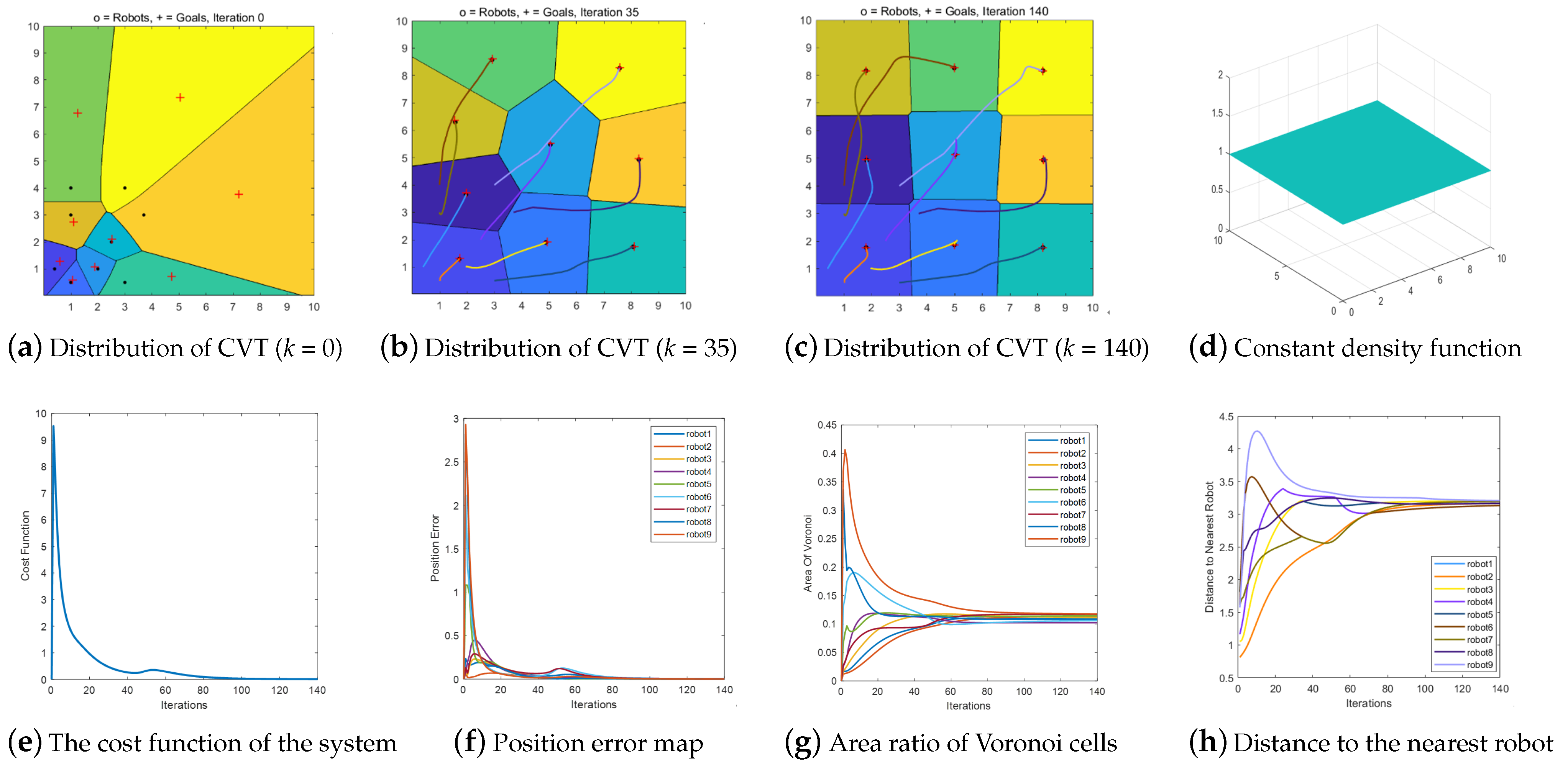
The simulation utilizes nine robots to verify the CVTs of multiple robots under the constant density function shown in Figure 8d. Figure 8a represents the initial positions of the robots. Herein, the black points represent the current position of the robot, the red crosses represent the centroid positions of the Voronoi cell, and the colored regions where the robots are located represent the Voronoi cell of the robots. Figure 8b illustrates the CVT in the robot task environment when the number of iterations k = 35. The colored curve represents the trajectory of the robot. Notably, each robot tracks its centroid in its Voronoi cell. Figure 8c shows the final configuration of all the robots under the constant density function, which is symmetrical; that is, the edge of the Voronoi cell between every two robots is located on the vertical bisector of the robots. Figure 8g,c reveal that the areas of the nine robots are equal. Moreover, the distribution conforms to the CVT characteristics, that is, the edges of the Voronoi cells are all located on the vertical bisector between the robots, and the areas of the cells are approximately equal. When measuring the workloads of the robots using the size of the work area, the workload of each robot is considered to be approximately equal.
Figure 8e shows that the cost function of the multi-robots finally reaches the minimum value, that is, the optimal solution. Figure 8f depicts the error of the current position of each robot relative to the position of the centroid in each iteration. Notably, the position error of each robot is zero when the iteration reaches 140, and the cost function of the system is also minimized. When the optimal distribution of multi-robots in the task environment is obtained, the experiment is stopped. According to the distance between each pair of consecutive robots during the process of the multi-robot movement, the robots can be observed to be at safe distances from each other, as shown in Figure 8h.
All the subsequent simulations in this study use nine robots. Their initial positions and corresponding parameters are listed in Table 1.
Scenario 2. Multi-robot motion control based on BUVC under constant density function.
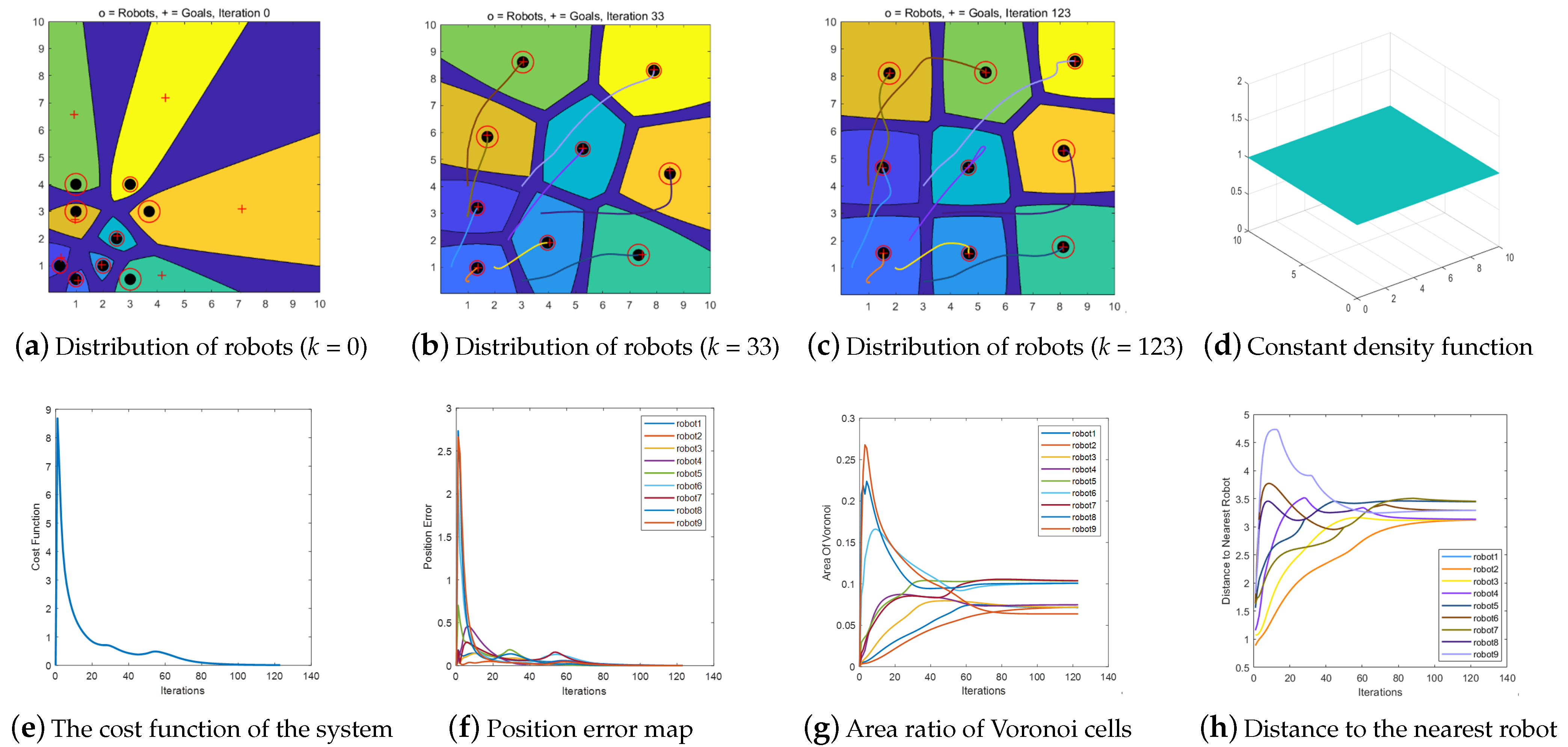
In this scenario, the initial positions of the robots are the same as those in Scenario 1, and the coverage motion control of multiple robots under the density function shown in Figure 9d is verified. Figure 9a shows the distribution of the Voronoi cells corresponding to the robot position when the number of iterations k = 0. The black discs represent the current positions and dimensions of the robots. As the sizes of the red circles increase, both the positioning uncertainties and positioning accuracies of the robot increase. The regions represent the Voronoi cells of the robots, and the dark blue areas between the Voronoi cells represent the buffer zones between the cells. Figure 9b shows the position distribution and trajectory diagram of the robot task environment when the number of iterations k = 33. Figure 9c represents the final configuration of multi-robot coverage under the constant density function. Figure 9c,g reveal that the buffer area of the Voronoi cell of a robot increases as the robot’s positioning uncertainty increases. This is consistent with the characteristics of the BUVC. This means that the boundary between the Voronoi cells is biased toward the side with less positioning uncertainty and divides the cells asymmetrically. The buffer zones of the cells represent robots that cannot be treated as single points.
Figure 9e indicates that the cost function of the multi-robots finally reaches the minimum value, that is, the optimal solution. Figure 9f shows that the position error of each robot tends to zero after 123 iterations. At this time, the optimal distribution of the robots in the task environment is obtained, and the iteration is stopped. Figure 9h shows that during the multi-robot movement, all the robots are at safe distances from each other.
Scenario 3. Multi-robot motion control of BUVC based on communication distance constraint under constant density function.
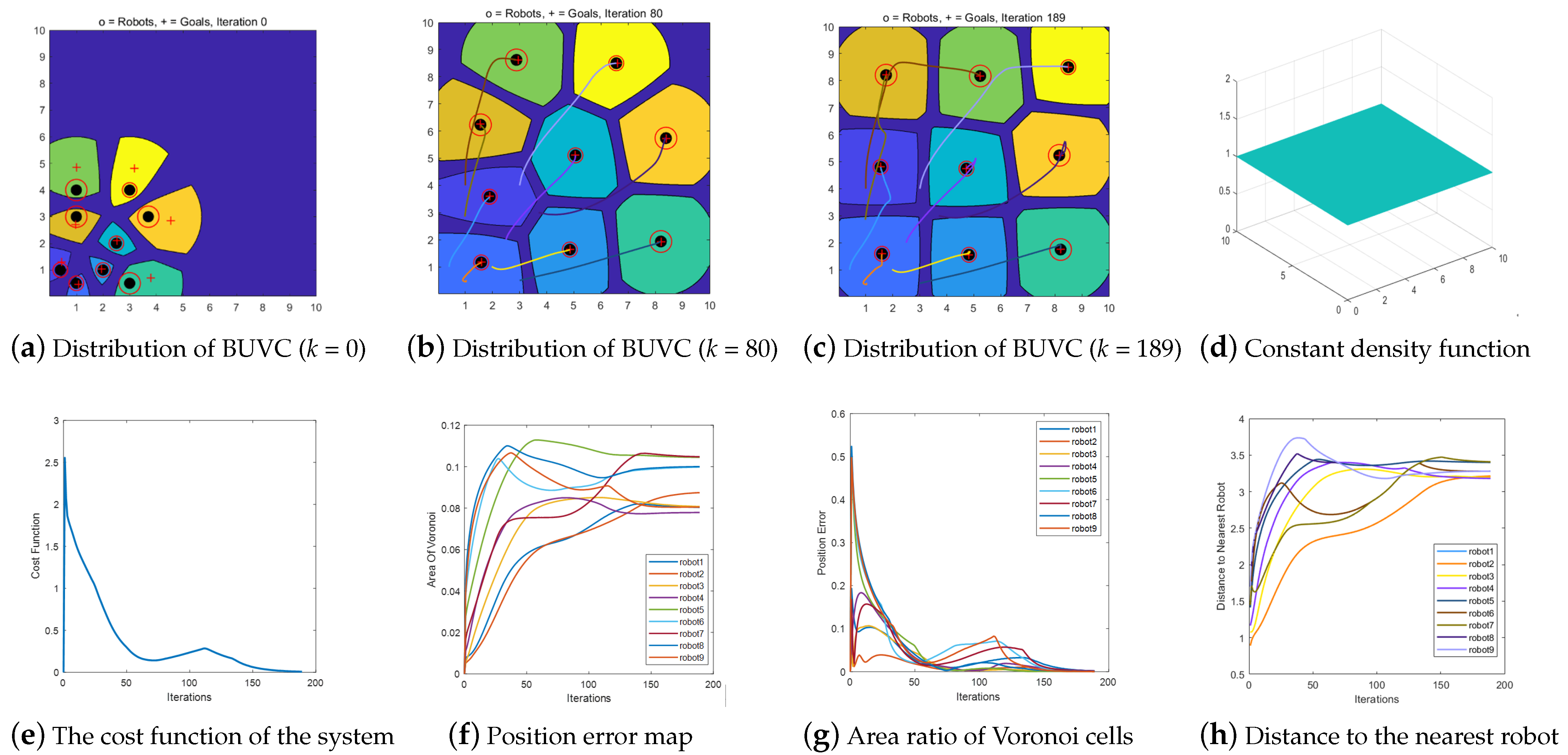
In this scenario, the initial positions of the robots are the same as those in Scenarios 1 and 2. Herein, we verify the coverage motion control of multiple robots under the density function shown in Figure 10d. Figure 10a represents the initial position of the robot. Herein, the Voronoi cells corresponding to the robots are all constrained to 0.5 times the communication range. Figure 10b shows the BUVC division in the robot task environment when the number of iterations k = 80. Figure 10c shows the final configuration of 10 robots under a constant density function, demonstrating an asymmetric distribution. Figure 10c,g indicate that the area of the Voronoi cell of a robot increases as the robot’s positioning uncertainty increases. Moreover, the Voronoi buffer between the robots is biased toward the side containing robots with low positioning uncertainties, and the distribution is asymmetric. This is consistent with the BUVC characteristics and in stark contrast with the final configuration of the BUVC without the communication range constraints, as shown in Figure 9c.
Figure 10e,f show that both the cost function and position error in the multi-robot operation tend to zero. Figure 10h shows that in the process of multi-robot motion, the robots are all at safe distances from each other.
Scenario 4. Multi-robot motion control of BUVC based on communication distance constraint under Gaussian density function.
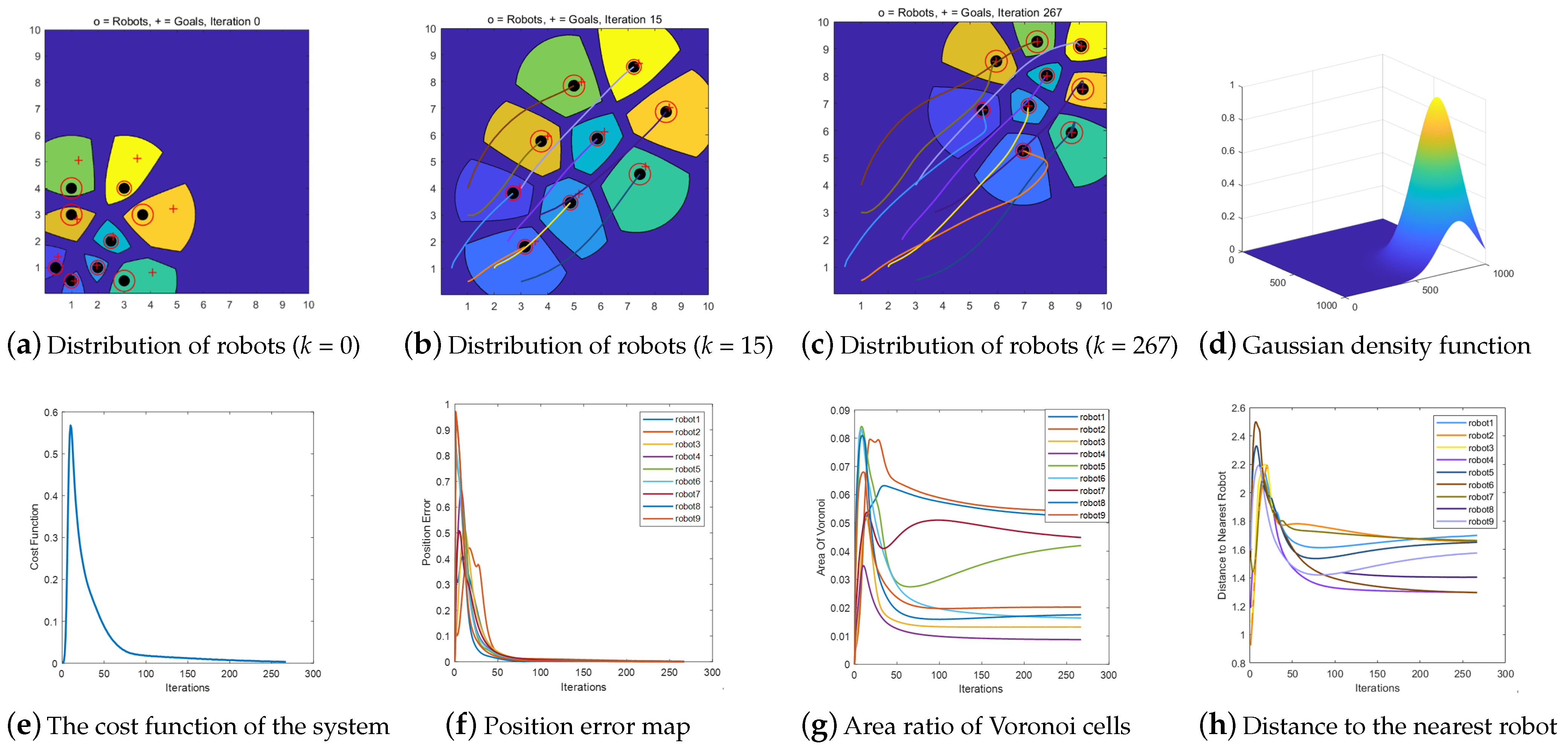
In this scenario, the initial positions of the robots are the same as those in Scenarios 1, 2, and 3. The coverage motion control of the multiple robots under the Gaussian density function, shown in Figure 11d, is verified. The density function is obtained using Equation (24). Figure 11a shows the initial positions of the robots. Figure 11c shows the final configuration of the nine robots under the Gaussian density function, demonstrating an asymmetric distribution. Figure 11c,g reveal that the area of the Voronoi cell of a robot increases as the robot’s positioning uncertainty increases. Moreover, the Voronoi buffer between the robots is biased toward the side containing robots with low positioning uncertainties, and the distribution is asymmetric, which is consistent with the BUVC characteristics.
σ ( x , y ) = e δ ( a ( x x c ) 2 + b ( y y c ) 2 ) 2
Figure 11e,f show that the cost function and position error of the multi-robot operation tend to zero. Figure 11h indicates that during the multi-robot motion, the robots are all at safe distances from each other.
Scenario 5. Multi-robot motion control of BUVC based on communication distance constraint under Gaussian density function.
In this scenario, the initial positions of the robots are the same as those in Scenarios 1, 2, 3, and 4. However, the presence of an obstacle in the upper right corner of the area under consideration transforms the area into a non-convex environment. The coverage motion control of the multi-robots under the Gaussian density function shown in Figure 12d is verified. The density function is obtained using Equation (24). Figure 12a shows the initial position of the robots. Figure 12c shows the final configuration of the nine robots under the Gaussian density function, showing an asymmetric distribution. Figure 12c,g show that the area of the Voronoi cell of a robot increases as the robot’s positioning uncertainty increases. Moreover, the Voronoi buffer between the robots is also biased toward the side containing robots with low positioning uncertainties, that is, the distribution is asymmetric. This is consistent with the BUVC characteristics. Figure 12e,f show that both the cost function and position error in the multi-robot operation tend to zero. Figure 12h shows that the robots are all at safe distances from each other during the multi-robot movement.
Scenario 6. Multi-robot motion control of BUVC based on communication distance constraint under Gaussian density function.
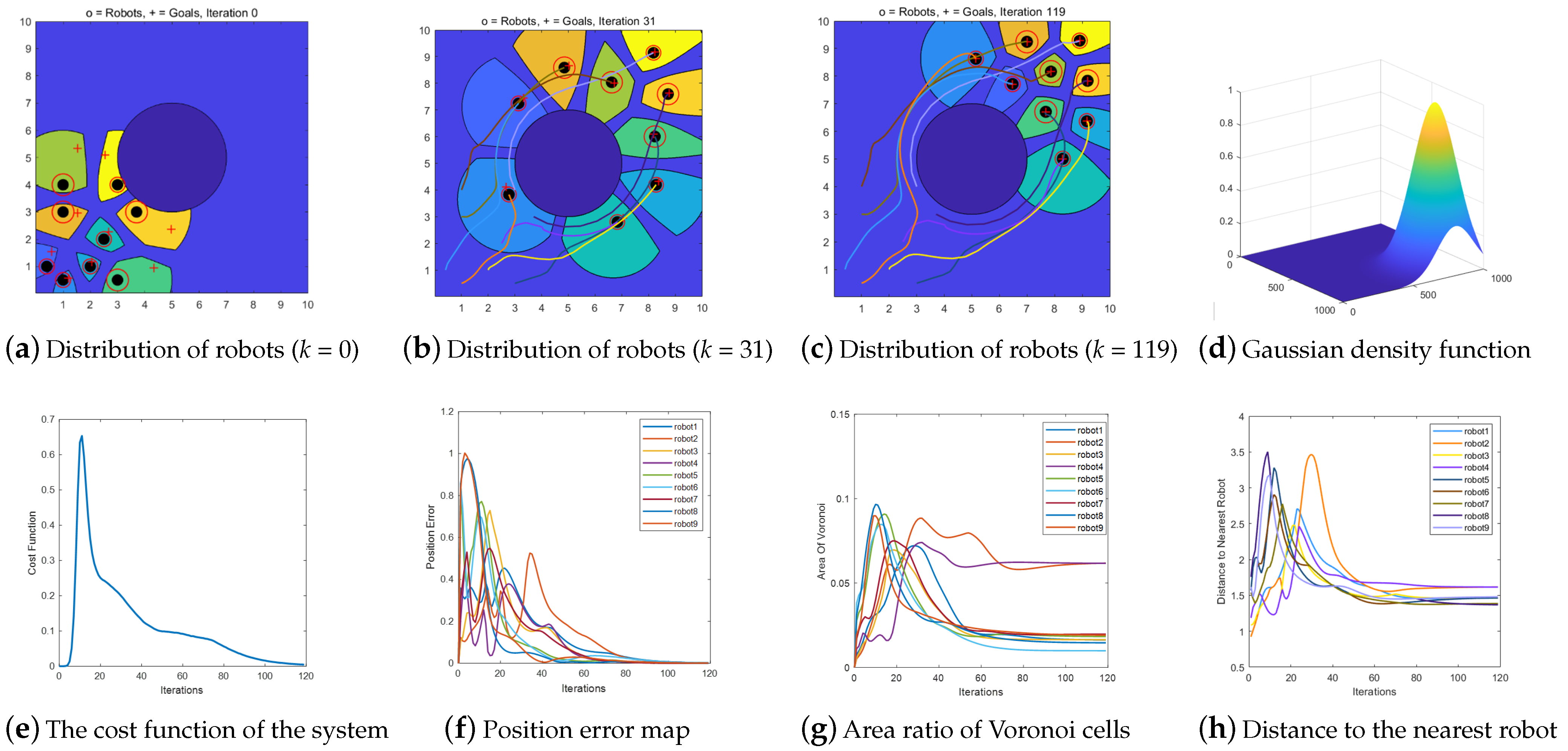
In this scenario, the initial positions of the robots are the same as those in Scenarios 1, 2, 3, 4, and 5. However, the presence of a circular obstacle in the middle of the area under consideration transforms the area into a non-convex environment. The coverage motion control of multi-robots under the Gaussian density function shown in Figure 13d is verified. The density function is obtained using Equation (24). Figure 13a shows the initial position of the robots. Figure 13c shows the final configuration of the nine robots under the Gaussian density function, which shows an asymmetric distribution. Figure 13c,g show that the area of the Voronoi cell of a robot increases as the robot’s positioning uncertainty increases. Moreover, the Voronoi buffer between the robots is also biased toward the side containing robots with low positioning uncertainties, that is, the distribution is asymmetric. This is consistent with the BUVC characteristics.
Figure 13e,f reveal that both the cost function and position error in the multi-robot operation tend to zero. Figure 13h shows that during the multi-robot movement, all the robots are at safe distances from each other.
The results of the multi-robot coverage simulations in the six scenarios are compared and analyzed. The comparison results are presented in Table 2. Notably, the number of iterations in Scenario 2 is less than that in Scenario 1, under stable conditions. This is because the existence of the buffer zone between the robots under the BUVC relatively reduces the area under consideration. This means that the area where the robots should operate is reduced, so the convergence speed is accelerated, which also reflects the advantages of the BUVC. However, the number of iterations and average position errors when the system is stable in both scenarios are the same. This shows that the method proposed in this study does not reduce the position accuracies of the robots when the positioning errors and actual sizes of the robots are considered.
By introducing communication distance constraints, the number of iterations in Scenario 3 is more than that in Scenario 2. This is because following the introduction of the communication distance constraint, the Voronoi regions of the robots are constantly reduced. Thus, the positions of the robots’ centroids are constrained, and the final number of iterations is increased.
One of the reasons for the reduction in the number of iterations in Scenarios 5 and 6 relative to that in Scenario 4 is that the introduction of obstacle areas in the task environment reduces the workspace. As the working area of the robots is reduced, the convergence speed of the robot-covering system is increased. Another reason is that the final to-be-covered area is partially occluded by obstacles. Therefore, the robot coverage system needs to adjust less frequently when it is almost stable.
7. ROS Robot Experiment

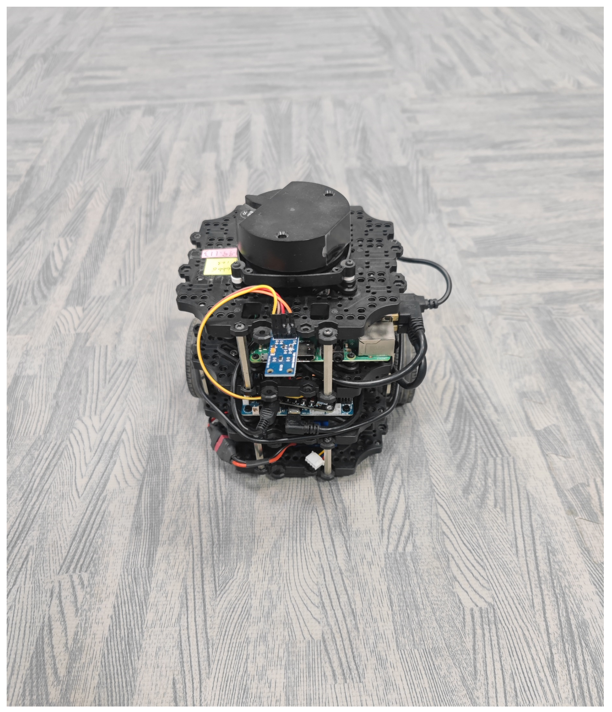
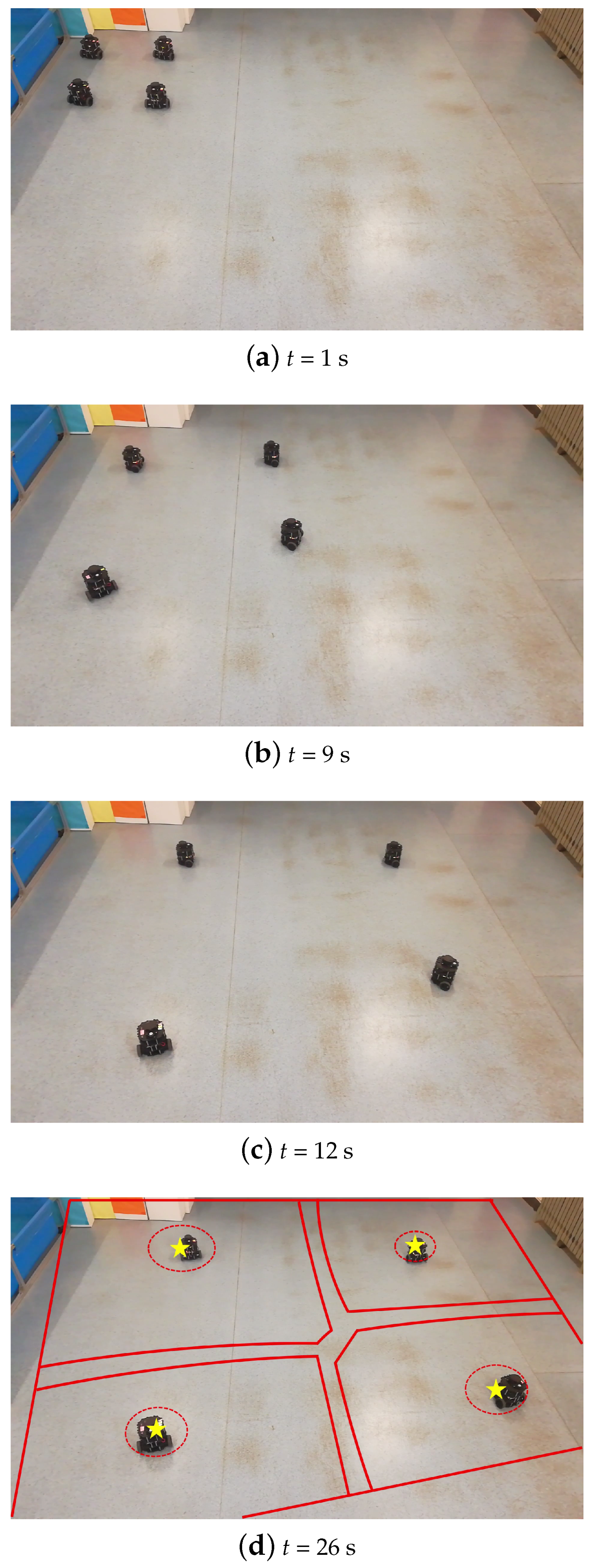
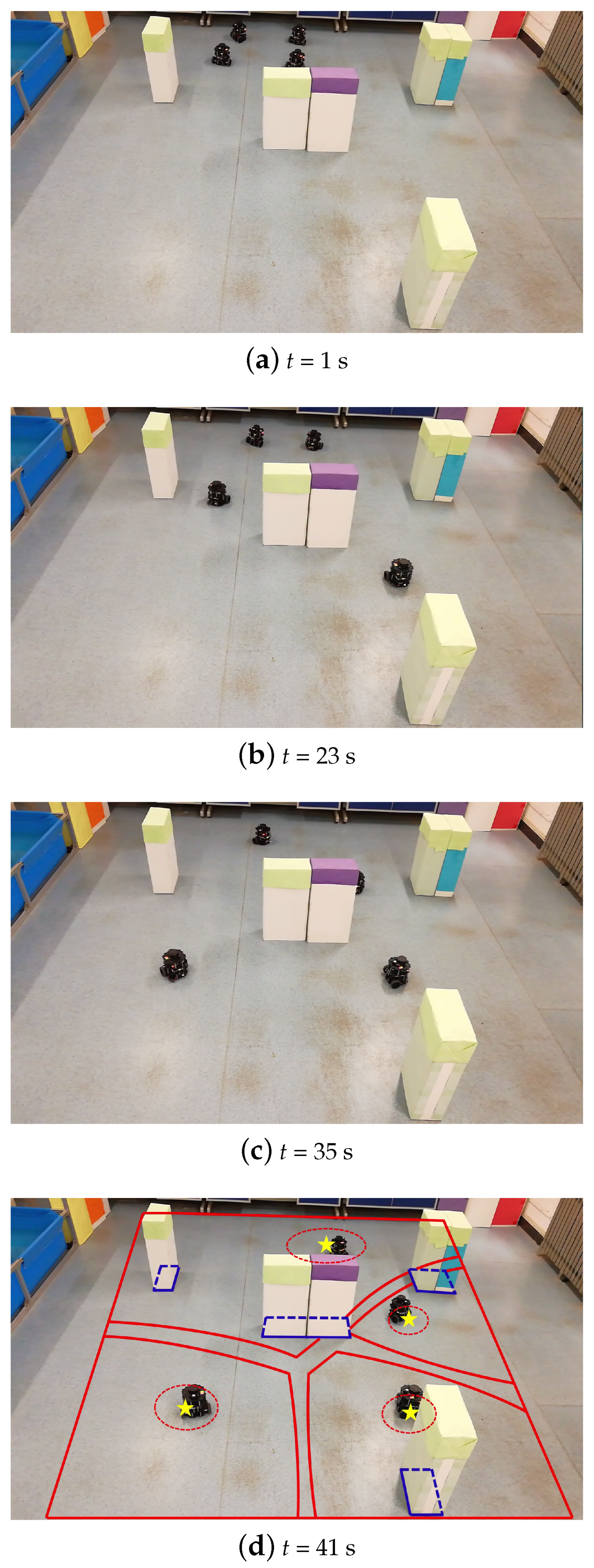
We set an experimental environment with size of 5 m × 5 m. In this experimental environment, we validated the feasibility of the algorithm using four Turtlebot3 robots, as shown in Figure 14. Two experiment scenarios were conducted: one with no obstacles and another with obstacles for the BUVC experiment. In both scenarios, the density function of the experimental environment remains a constant density function, and the initial positions of the robots are consistently located in the top left corner. The size radius of each robot was set to 0.15 m, with uncertainties defined as λ 1 = 0.8, λ 2 = 0.7, λ 3 = 0.6 and λ 4 = 0.3, respectively. The maximum velocity of the robots in the experiment was 1 m/s. At the beginning of the experiment, it was assumed that each robot had knowledge of the environmental density information and the obstacle positions.
The main procedure of the experiment is as follows: (a) The environment map is constructed using Simultaneous Localization and Mapping (SLAM) technology to enable the robots to acquire real-time global position information. (b) The robots transmit their positional data to the control terminal (computer) through the Robot Operating System (ROS) control system. (c) The control terminal employs the BUVC algorithm to calculate the centroid’s position for the next step and sends control commands to the TurtleBot3 robots. (d) The robots continuously track the centroid’s position until the algorithm convergence condition is met.

7.1. CVT in Obstacle-Free Scenario

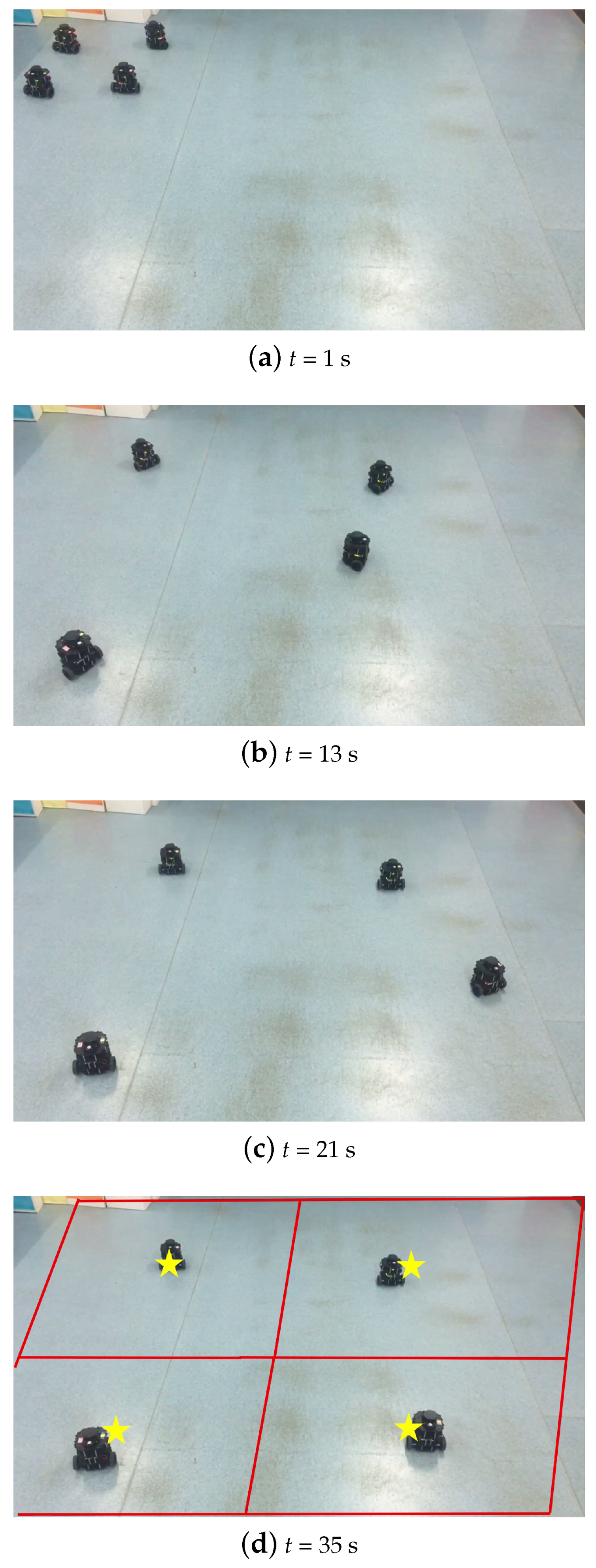
In the obstacle-free scenario, the primary task of the robots is to achieve a complete coverage of the designated area. The experimental process is illustrated in Figure 15, where irregular polygons represented by red lines depict the Voronoi cells of different robots, and yellow pentagrams indicate the centroid positions of the Voronoi cells.

7.2. BUVC in Obstacle-Free Scenario

With the same experimental setup as described above, the BUVC is employed for area coverage. The overall formation process based on this algorithm is illustrated in Figure 16. It can be observed that the robots achieve the final allocation after 26 s, as shown in Figure 16d.

7.3. BUVC in Obstacle Scenario

In the obstacle environment, we set a square obstacle as shown in Figure 17a. Due to the absence of obstacle avoidance strategies in the original CVT, robots may collide with obstacles during formation. The introduction of obstacle avoidance strategies enables robots to execute obstacle avoidance strategies based on known obstacle information, ultimately completing BUVC partitioning under obstacles. As shown in Figure 17d, the four robots reached the centroid position at 41 s, indicating algorithm convergence.
The effectiveness of the proposed algorithm was verified by deploying it on the Turtlebot3 robots. In the experiment of this section, constant density function is used as the control input of CVT, respectively, and two scenarios, namely obstacle-free and square obstacle environments, are used for the experiment. The feasibility of the algorithm was confirmed by assigning different constraint Voronoi cells to each robot. Furthermore, the performance of the algorithm remained robust when the density function was changed to elliptical or linear density functions. It is worth noting that due to the self-positioning error of the TurtleBot3 and the odometer error caused by the tire slip, there exists some deviation between the final position of the robot and the center of mass position.

8. Conclusions

In this study, we proposed a buffer uncertain Voronoi cell with communication distance constraints in a non-convex environment to optimize the multi-robot formation control strategy while improving the robustness of the formation. The main contents of the work are summarized as follows:
1.
In the traditional CVT, an actual robot cannot be treated as a single point. To address this limitation, we created a buffer zone between the Voronoi cells by introducing the radius weight of the robot. Subsequently, we shrank the edge of the Voronoi cell to the safe radius of the robot to improve the collision avoidance performance of the robot when it was close to the boundaries.
2.
Second, considering the inherent positioning error in the positioning system, a positioning uncertainty factor was introduced as a weighting value. Consequently, the robots had high positioning uncertainty factors. In other words, the size of a Voronoi cell increased with an increase in the value of the position error. The size of the Voronoi cell could be varied in the area under consideration according to the positioning error of the current robot, thereby further improving the collision avoidance performance and robustness of the BUVC division in the process of a multi-robot formation movement.
3.
Next, considering the limitation of the non-convex environment of the traditional CVT, this study realized a BUVC partition in a non-convex environment by introducing a discretized Voronoi partition and non-convex constraints. Moreover, the challenge of the unreachable centroid in a non-convex environment was solved by a non-visibility area and the corresponding obstacle avoidance strategy. This enabled the robots to achieve an effective area division for non-convex working areas with obstacles and ensured their working safety during the working process.
4.
Given the limited communication distance of the robots in practice, this study constrained the BUVC of each robot in the non-convex environment obtained through the communication distance constraint. Furthermore, we addressed challenges such as robot collision, deterioration of the cost function, and failure to consider the centroid of the cell that may generate errors under the condition of limited communication distance.
Finally, the proposed algorithm was improved with regard to the traditional CVT, and the robustness of the proposed algorithm to the formation of robots with communication distance constraints, actual sizes, and positioning errors in a non-convex environment were simulated in six simulation scenarios and two experiments. Thus, the innovation and effectiveness of the proposed algorithm were validated.
In future work, we will extend the proposed algorithm to more complex obstacle environments, including 3D environments for multi-robot formation control. Another future work will consist of the adjustment of the Voronoi division of designated areas in time to restore the stable state of a multi-robot system in a short time when a robot fails or a new robot joins the system.

Author Contributions

Conceptualization, K.C., Y.C. and S.G.; Methodology, K.C. and D.A.; Software, K.C. and H.D.; Validation, K.C., Y.C., H.D. and D.A.; Formal analysis, K.C.; Investigation, K.C. and D.A.; Data curation, H.D. and D.A.; Writing—original draft, K.C.; Writing—review & editing, Y.C. and S.G.; Visualization, H.D.; Supervision, Y.C. and S.G.; Project administration, S.G.; Funding acquisition, S.G. All authors have read and agreed to the published version of the manuscript.

Funding

This research was funded by the National Natural Science Foundation of China grant number 62103315, the Key R & D Program Project of Shaanxi Province grant number 2022GY-238, 2022GY-242, 2022GY-243 and the Key Industrial Innovation Chain Project of Shaanxi Province grant number 2022QFY01-16, 2023-ZDLNY-63.

Data Availability Statement

Data sharing is not applied.

Acknowledgments

The authors are grateful to the reviewers for their valuable suggestions.And grateful to the Shaanxi Autonomous Systems and Intelligent Control International Joint Research Center for providing the experimental field and MESA Lab.

Conflicts of Interest

The authors declare no conflict of interest.

References

  1. Kaushal, P.; Khurana, M.; Ramkumar, K.R. A systematic review of swarm intelligence algorithms to perform routing for VANETs communication. ECS Trans. 2022, 107, 5027. [Google Scholar] [CrossRef]
  2. Zong, X.; Yi, J.; Wang, C. An Artificial Fish Swarm Scheme Based on Heterogeneous Pheromone for Emergency Evacuation in Social Networks. Electronics 2022, 11, 649. [Google Scholar] [CrossRef]
  3. Bredeche, N.; Fontbonne, N. Social learning in swarm robotics. Philos. Trans. R. Soc. B Biol. Sci. 2022, 377, 20200309. [Google Scholar] [CrossRef]
  4. Si, L.; Shu, L.; Wang, M. Study on forest fire danger prediction in plateau mountainous forest area. Nat. Hazards Res. 2022, 2, 25–32. [Google Scholar] [CrossRef]
  5. Bailon-Ruiz, R.; Bit-Monnot, A.; Lacroix, S. Real-time wildfire monitoring with a fleet of UAVs. Robot. Auton. Syst. 2022, 152, 104071. [Google Scholar] [CrossRef]
  6. Yadav, S.K.; Tiwari, K.; Pandey, H.M. A review of multimodal human activity recognition with special emphasis on classification, applications, challenges and future directions. Knowl.-Based Syst. 2022, 223, 106970. [Google Scholar] [CrossRef]
  7. Kantaros, Y.; Schlotfeldt, B.; Atanasov, N. Sampling-based planning for non-myopic multi-robot information gathering. Auton. Robot. 2021, 45, 1029–1046. [Google Scholar] [CrossRef]
  8. Alitappeh, R.J.; Jeddisaravi, K. Multi-robot exploration in task allocation problem. Appl. Intell. 2022, 52, 2189–2211. [Google Scholar] [CrossRef]
  9. Chen, Y.Q.; Wang, Z.; Liang, J. Optimal dynamic actuator location in distributed feedback control of a diffusion process. Int. J. Sens. Netw. 2007, 2, 169–178. [Google Scholar] [CrossRef]
  10. Chen, Y.Q.; Wang, Z.; Liang, J. Actuation scheduling in mobile actuator networks for spatial-temporal feedback control of a diffusion process with dynamic obstacle avoidance. IEEE Int. Conf. Mechatron. Autom. 2005, 2, 752–757. [Google Scholar]
  11. Abpeikar, S.; Kasmarik, K.; Tran, P.V. Tuning swarm behavior for environmental sensing tasks represented as coverage problems. In Artificial Intelligence and Data Science in Environmental Sensing; Academic Press: New York, NY, USA, 2007; pp. 9122–9151. [Google Scholar]
  12. Fernando, M.; Senanayake, R.; Swany, M. CoCo Games: Graphical Game-Theoretic Swarm Control for Communication-Aware Coverage. IEEE Robot. Autom. Lett. 2022, 7, 5966–5973. [Google Scholar] [CrossRef]
  13. Cortes, J.; Martinez, S.; Karatas, T. Coverage control for mobile sensing networks. IEEE Trans. Robot. Autom. 2004, 20, 243–255. [Google Scholar] [CrossRef]
  14. Chen, J.; Zhuang, B.; Chen, Y.Q. Diffusion control for a tempered anomalous diffusion system using fractional-order PI controllers. ISA Trans. 2018, 82, 94–106. [Google Scholar] [CrossRef]
  15. Graham, R.; Cortés, J. Asymptotic optimality of multicenter Voronoi configurations for random field estimation. IEEE Trans. Autom. Control 2009, 54, 153–158. [Google Scholar] [CrossRef]
  16. Chevet, T.; Maniu, C.S.; Vlad, C. Chance-constrained MPC for Voronoi-based multi-agent system deployment. IFAC-Pap. 2020, 53, 6969–6974. [Google Scholar] [CrossRef]
  17. Hatleskog, J.; Olaru, S.; Hovd, M. Voronoi-based deployment of multi-agent systems. In Proceedings of the 2018 IEEE Conference on Decision and Control, Miami, FL, USA, 17–19 December 2018; pp. 5403–5408. [Google Scholar]
  18. Mahboubi, H.; Moezzi, K.; Aghdam, A.G. Distributed deployment algorithms for efficient coverage in a network of mobile sensors with nonidentical sensing capabilities. IEEE Trans. Veh. Technol. 2014, 63, 3998–4016. [Google Scholar] [CrossRef]
  19. Mahboubi, H.; Moezzi, K.; Aghdam, A.G. Distributed sensor coordination algorithms for efficient coverage in a network of heterogeneous mobile sensors. IEEE Trans. Autom. Control 2017, 62, 5954–5961. [Google Scholar] [CrossRef]
  20. Wang, D.; Liu, J.; Zhang, Q. Mobility-assisted sensor networking for field coverage. In Proceedings of the IEEE Globecom 2007-IEEE Global Telecommunications Conference, Washington, DC, USA, 26–30 November 2007; pp. 1190–1194. [Google Scholar]
  21. Caicedo-Nunez, C.H.; Zefran, M. A coverage algorithm for a class of non-convex regions. In Proceedings of the IEEE Conference on Decision & Control, Cancun, Mexico, 9–11 December 2008; pp. 4244–4249. [Google Scholar]
  22. Xu, X.; Diaz-Mercado, Y. Multi-robot Control Using Coverage Over Time-Varying Non-Convex Domains. In Proceedings of the IEEE International Conference on Robotics and Automation, Paris, France, 17–21 May 2020; pp. 4536–4542. [Google Scholar]
  23. Nair, V.G.; Guruprasad, K.R. GM-VPC: An Algorithm for Multi-robot Coverage of Known Spaces Using Generalized Voronoi Partition. Robotica 2019, 38, 1–16. [Google Scholar] [CrossRef]
  24. Breitenmoser, A.; Schwager, M.; Metzger, J.C. Voronoi coverage of non-convex environments with a group of networked robots. In Proceedings of the IEEE International Conference on Robotics and Automation, Anchorage, Alaska, 3–8 May 2010; pp. 4982–4989. [Google Scholar]
  25. Lu, L.; Choi, Y.K.; Wang, W. Visibility-based coverage of mobile sensors in non-convex domains. In Proceedings of the 2011 Eighth International Symposium on Voronoi Diagrams in Science and Engineering, Qingdao, China, 28–30 June 2011; pp. 105–111. [Google Scholar]
  26. Mahboubi, H.; Sharifi, F.; Aghdam, A.G. Distributed control of multi-agent systems with limited communication range in the fixed obstacle environments. IEEE Access 2019, 7, 118259–118268. [Google Scholar] [CrossRef]
  27. Pierson, A.; Figueiredo, L.C.; Pimenta, L.C. Adapting to sensing and actuation variations in multi-robot coverage. Int. J. Robot. Res. 2017, 36, 337–354. [Google Scholar] [CrossRef] [Green Version]
  28. Turanli, M.; Temeltas, H. Multi-robot Energy-Efficient Coverage Control with Hopfield Networks. Stud. Inform. Control 2020, 29, 179–188. [Google Scholar] [CrossRef]
  29. Papatheodorou, S.; Stergiopoulos, Y.; Tzes, A. Distributed area coverage control with imprecise robot localization. In Proceedings of the 24th Mediterranean Conference on Control and Automation (MED), Athens, Greece, 21–24 June 2016; pp. 214–219. [Google Scholar]
  30. Papatheodorou, S.; Tzes, A.; Giannousakis, K. Distributed area coverage control with imprecise robot localization: Simulation and experimental studies. Int. J. Adv. Robot. Syst. 2018, 15, 1729881418797494. [Google Scholar] [CrossRef] [Green Version]
  31. Daniel, A.D.; Armando, A.N.; Leonardo, A.M.; Fernando, O.S. Control and Reorganization of Heterogeneous Vehicle Platoons after Vehicle Exits and Entrances. Int. J. Control Autom. Syst. 2022, 20, 2437–2446. [Google Scholar]
  32. Cao, K.; Chen, Y.Q.; Gao, S.; Dang, H.X. Multi-robot Formation Control Based on CVT Algorithm and Health Optimization Management. Appl. Sci. 2022, 12, 755. [Google Scholar] [CrossRef]
Figure 1. Schematic diagram of Voronoi cells.
Applsci 13 08530 g001
Figure 2. Multi-robot distribution before and after introducing uncertainty and robot size wright.
Applsci 13 08530 g002
Figure 3. Non-convex environment.
Applsci 13 08530 g003
Figure 4. BUVC in non-convex environment.
Applsci 13 08530 g004
Figure 5. BUVC before and after introducing limited communication range.
Applsci 13 08530 g005
Figure 6. BUVC before and after the introduction of invisible area.
Applsci 13 08530 g006
Figure 7. Schematic diagram of obstacle avoidance strategy.
Applsci 13 08530 g007
Figure 8. CVT distribution and related data of multi-robot under constant density function.
Applsci 13 08530 g008
Figure 9. Multi-robot motion control based on BUVC under constant function.
Applsci 13 08530 g009
Figure 10. BUVC distribution and related data for multi-robot with communication distance constraints under constant density function.
Applsci 13 08530 g010
Figure 11. Multi-robot coverage motion control based on BUVC under Gaussian density function.
Applsci 13 08530 g011
Figure 12. BUVC distribution and related data for multi-robot with communication distance constraints in a non-convex environment.
Applsci 13 08530 g012
Figure 13. Multi-robot coverage control based on BUVC in non-convex environment.
Applsci 13 08530 g013
Figure 14. Turtlebot3.
Applsci 13 08530 g014
Figure 15. Formation experiment of obstacle-free scenario under CVT.
Applsci 13 08530 g015
Figure 16. Formation experiment of obstacle-free scenario under BUVC.
Applsci 13 08530 g016
Figure 17. Formation experiment of obstacle scenario under BUVC.
Applsci 13 08530 g017
Table 1. Initial positions and corresponding parameters of the nine robots.
    p 1 p 2 p 3 p 4 p 5 p 6 p 7 p 8 p 9
Coordinate p ( k = 0 ) (0.4, 1)(1, 0.5)(2, 1)(2.5, 2)(3, 0.5)(1, 4)(1, 3)(3.7, 3)(3, 4)
Radius r i 0.20.20.20.20.20.20.20.20.2
Positioning uncertainty λ i 0.50.50.50.50.50.50.50.50.5
Table 2. Comparison of simulation results of multi-robot formation based on BUVC in six scenarios.
AlgorithmScenariosThe Number of Iterations when the System Is StableCost Function when the System Is StableAverage Position Error When the System Is Stable
Convex environmentCVTScenarios 11400.00740.00083
BUVC+Communication distance constraintsScenarios 21230.00790.00094
Scenarios 31890.00780.00012
Scenarios 42670.00190.00089
Non-convex environmentScenarios 51460.00360.00110
Scenarios 61190.00470.00121
Disclaimer/Publisher’s Note: The statements, opinions and data contained in all publications are solely those of the individual author(s) and contributor(s) and not of MDPI and/or the editor(s). MDPI and/or the editor(s) disclaim responsibility for any injury to people or property resulting from any ideas, methods, instructions or products referred to in the content.