Article

Research on Active Precontrol Strategy for Shape and Performance of Helicopter Spiral Bevel Gears

1
School of Mechanical Engineering, Jiangnan University, Wuxi 214122, China
2
Jiangsu Pacific Precision Forging Co., Ltd., Taizhou 225500, China
3
Jiangsu Key Laboratory of Advanced Food Manufacturing Equipment and Technology, Wuxi 214122, China
4
College of Mechanical and Electrical Engineering, Nanjing University of Aeronautics and Astronautics, Nanjing 210016, China
*
Author to whom correspondence should be addressed.
These authors contributed equally to this work.
Appl. Sci. 2023, 13(14), 8527; https://doi.org/10.3390/app13148527
Submission received: 1 June 2023 / Revised: 1 July 2023 / Accepted: 13 July 2023 / Published: 24 July 2023

Abstract

:
Gear vibration becomes unmanageable under extreme conditions, which shortens the time between overhauls of the helicopter reducer and affects the service efficiency of helicopters. For this purpose, an active precontrol strategy for shape and performance was developed for spiral bevel gear (SBG) systems, thus prolonging the reliable service period of helicopters. Firstly, the perfect pinion surface was built based on the preset contact path (CP) and transmission error (TE). Secondly, through a combination of tooth contact analysis (TCA) and loaded tooth contact analysis (LTCA), the loaded transmission error (LTE), meshing stiffness (MS), and meshing impact (MI) of the SBG transmission were obtained. Thirdly, an eight-degrees-of-freedom (8-DOF) dynamic model was built, and a simplified dynamic model was generated based on this. As regards the dynamic response, the root mean square of normal vibration acceleration (RMA) of the SBG transmission was obtained by solving the differential equation of motion. The RMA of the SBG transmission was also analysed based on the basic theory of vector structural mechanics. Finally, an optimization model aimed at reducing the RMA of the SBG transmission was established using ease-off, and a redesigned SBG transmission with good dynamic performance was obtained through optimization. Simulation analysis showed that the LTE and MS amplitudes of the optimized gear were smaller than those of the original gear. The impact force and impact velocity of the optimized gear were 27.02% and 25.81%, respectively, lower than those of the original gear. The RMA value of the optimized gear was much lower than that of the original gear. The normal vibration velocity and displacement of the optimized gear transmission were also cut down. Therefore, the design approach can effectively increase the performance of gear transmission.

1. Introduction

Due to the advantages of having a strong loaded capacity, smooth transmission, and low noise, SBG systems are used in the power transmission systems of airplanes. They are the key components of the transmission system and have high requirements in all aspects. With technological advancements, SBG systems are becoming more high-speed and heavy-load, but their running vibration is also becoming more and more severe. Flank redesign is one of the most effective methods for reducing SBG transmission vibration and improving their dynamic performance.
Research on SBG transmissions mainly focuses on the static characteristics due to the complex flank geometry, and the optimization goal is to lower the LTE amplitude. Tang Jinyuan analysed the influence of the TE on the gear dynamic characteristics [1]. Wang improved the gear dynamic characteristics by optimizing the machining settings based on the local synthesis method [2]. Simon put forward a novel way to cut down the LTE of gears by optimizing their machining settings [3,4,5,6,7,8]. Astoul put forward an innovative means for lowering the LTE amplitude of gears based on the optimization process [9]. Based on ease-off technology, Artoni minimized the LTE amplitude of hypoid gears [10,11], and Kolivand put forward a method to lower the LTE of gear pairs and improve meshing performance [12,13]. Jiang Jinke put forward the optimization method to improve the meshing performance of hypoid gears [14,15]. Cao Xuemei analysed the vibration mechanism and then summarized an approach to lower the vibration of gears [16]. Kong proposed an innovative adaptive data-driven loaded transmission error modelling, prediction and optimal control system by modifying misalignment evaluations [17]. Mu proposed a novel wave-tooth-surface design method to reduce the loaded transmission error of high-contact-ratio spiral bevel gears based on ease-off technology [18]. However, the flank design parameters that offer gear transmission the best static meshing performance may not offer the best dynamic performance [19].
To overcome the defects of Gleason technology, Litvin put forward a “local synthesis method (LSM)” [20,21]. Fang further improved the LSM [22]. The Orlikon Company proposed ease-off technology, which has become a research hotspot regarding flank design for SBG transmissions. Ease-off topography was introduced to LTCA technology for gear transmission by Kolivand [12,13]. Shih [23,24] and Su [25] proposed an ease-off approach to improving the meshing performance of gears. Artoni [26,27] proposed a means for improving the functional property of hypoid gears. Based on the theory of rack-gear common-tangential conjugate generation, Wei studied the construction of an ease-off surface by means of the topology modification of a polynomial surface [28]. Chen presented a direct preset method for solving the ease-off tooth surface of spiral bevel gears and achieving the global integrated control of the spiral bevel gear tooth surface [29]. Peng proposed a manufacturing process for fabricating ease-off surfaces for face gear drives that delivered controllable unloaded meshing performance and local bearing contact [30]. Wang proposed an approach for designing fourth-order transmission motion based on ease-off modification for spiral bevel gears [31]. Mu proposed an ease-off flank modification method for high-contact-ratio spiral bevel gears to improve the dynamic performance of spiral bevel gear transmissions [32,33]. Wang proposed an approach entailing ease-off flank modification for hypoid gears to improve the meshing performance of automobile drive axles [34]. Li proposed a new active ease-off topography modification approach for hypoid gears to improve the meshing performance based on a fourth-order transmission error model and a modified error sensitivity analysis method [35]. However, ease-off technology is mainly used in research into the static characteristics of gears, and flank design is carried out with the goal of minimizing the LTE of gears. Considering this issue, Mu proposed a novel multi-objective optimization method for reducing the LTE and the MI based on ease-off to control SBG transmission vibration [36]. The research results of flank modification on the basis of ease-off to maximise the dynamic characteristic of gears have not been published.
The most common methods for studying the vibration response characteristics of SBG transmissions are the finite element method (FEM) and the lumped mass method. The lumped mass method has a fast calculation speed, but the selection of excitation parameters has a certain degree of subjectivity, which affects the objectivity and accuracy of the calculation. The FEM model is precise and highly simulated, which can produce the most realistic reflection of the vibration characteristics of gears, but it takes a long calculation time and has poor convergence. Professor Ding of Purdue University proposed that vector structural mechanics has good convergence, low grid sensitivity, and strong objectivity of the model [37], which provides a new idea for the vibration response research of high-speed SBG system but lacks the dynamic theory applicable to the SBG system. Hou proposed a calculation expression for vector finite elements and hexahedral elements and analysed the meshing quality of the SBG system [38].
To control the SBG transmission vibration, and increase the time between overhauls of the main reducer of helicopters, thereby improving the utilization rate of helicopters, an active precontrol strategy for shape and performance for helicopter SBG transmission is proposed. Firstly, the perfect pinion surface is built with the ease-off method. Secondly, combined with TCA and LTCA, the LTE, MS and MI of the SBG transmission are obtained. Thirdly, the RMA of the SBG transmission is obtained based on the lumped mass method, in which the MS excitation, LTE excitation and MI excitation are applied to the dynamic model. Finally, an optimization model aimed at reducing the RMA of the SBG transmission was established with ease-off, and the redesigned SBG transmission with good dynamic performance was obtained through optimization. The RMA of the SBG transmission was also analysed with the structural dynamics method based on the basic theory of vector structural mechanics to verify the effectiveness of active precontrol strategy of vibration for helicopter SBG transmission. This exploration serves a significant technique for bettering the SBG transmission capability.

2. Design of Perfect Surface

The basic principle for the design of the perfect surface is as follows. Firstly, the pinion auxiliary tooth surface is built based on the preset TE. Secondly, the CP on pinion surface and its modification curve along the instantaneous meshing line are preset based on the design requirements. Thirdly, the correction value of the auxiliary pinion surface along the instantaneous meshing line is calculated, and it is superimposed on the pinion auxiliary surface. After this, the perfect pinion surface, which satisfied the functional requirements, is obtained. The detailed process is as follows.
According to the designed contact ratio, the CP is designed as follows:
y = ( x - x M ) tan η + y M
where xM and yM denote the coordinate of reference point, and η is the direction angle.
According to the functional requirements, the transmission error curve of the SBG transmission is designed as follows:
δ φ 2 = 0.5 m 21 ( φ 1 - φ 1 ( 0 ) ) 2
where φ1 and φ1(0) denote the actual and original pinion meshing angle, and m′21 denotes the first derivative of the contact ratio function.
According to the machining theory, the gear surface is built as follows:
r 2 = r 2 ( s g , θ g , φ g ) n 2 = n 2 ( s g , θ g , φ g ) f 2 ( s g , θ g , φ g ) = 0
where n2 and r2 denote gear normal and position vector, θg and sg are the flank parameter, f2 denotes the meshing equation, and φg is the gear cradle angle.
According to the meshing process of the SBG transmission, the auxiliary pinion surface is generated with the gear surface used as the cutter as follows:
r 1 = M 1 h ( φ 1 ) M h 2 ( φ 2 ) r 2 n 1 = L 1 h ( φ 1 ) L h 2 ( φ 2 ) n 2 f 12 ( s g , θ g , φ g , φ 1 ) = 0
where φ1 and φ2, respectively, denote the pinion meshing angle and the gear cutter meshing angle, and f12 denotes the meshing equation. Mh2 and M1h are the coordinate transform matrices. L1h and Lh2 are the upper-left 3 × 3 submatrices of M1h and Mh2.
M h 2 = cos Σ sin Σ sin φ 2 sin Σ cos φ 2 0 0 cos φ 2 sin φ 2 0 sin Σ cos Σ sin φ 2 cos Σ cos φ 2 0 0 0 0 1   M 1 h = 1 0 0 0 0 cos φ 1 sin φ 1 0 0 sin φ 1 cos φ 1 0 0 0 0 1
To obtain the perfect pinion surface shown in Figure 1, the auxiliary pinion surface obtained through Equation (4) needs to be modified along the meshing line. And in Figure 1, the blue line is the perfect pinion surface, and the black line is the auxiliary pinion surface.
The position vectors of the perfect surface (Figure 1) are obtained as follows:
p i = p i + n i δ y i
where p and n denote the position and normal vectors of the auxiliary pinion surface, and δy denotes the correction.

3. Analysis of Dynamic Performance

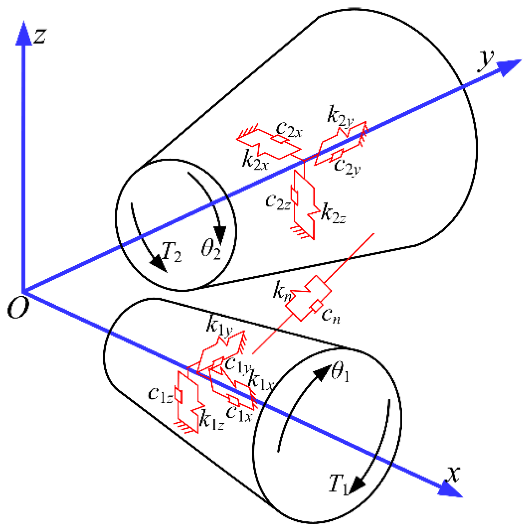
3.1. Dynamic Analysis Based on Lumped Mass Method

The SBG transmission dynamic equation (Equation (6)) is built based on the 8-DOF dynamic model with the lumped mass method (Figure 2) [39]. The 2-DOF dynamic model was established by simplifying the 8-DOF dynamic model, and the dynamic equation is built as Equation (7). Finally, the RMA is counted by applying the MS excitation, LTE excitation and MI excitation to the dynamic model. The MS and the LTE are counted using the LTCA method. The MI is counted with the MI theory [40].
m 1 X ¨ 1 + c 1 x X ˙ 1 + k 1 x X 1 = F x m 1 Y ¨ 1 + c 1 y Y ˙ 1 + k 1 y Y 1 = F y m 1 Z ¨ 1 + c 1 z Z ˙ 1 + k 1 z Z 1 = F z J 1 θ ¨ 1 = T 1 F n r 1 + F s r 1 m 2 X ¨ 2 + c 2 x X ˙ 2 + k 2 x X 2 = F x m 2 Y ¨ 2 + c 2 y Y ˙ 2 + k 2 y Y 2 = F y m 2 Z ¨ 2 + c 2 z Z ˙ 2 + k 2 z Z 2 = F z J 2 θ ¨ 2 = T 2 + F n r 2 F s r 2
where Fs represents the impact force, and it is obtained based on the impact theory.
Fn represents the normal load, and
F n = k n ( t ) f ( λ n ) + c n λ ˙ n
kn represents the meshing stiffness. The LTE and MS are obtained by LTCA.
λn represents the normal relative displacement of the gear meshing point.
Fx, Fy, Fz represent the components of a normal load Fn along the x, y and z axes, respectively.
F x = a 1 F n F y = a 2 F n F z = a 3 F n
ai(i = 1, 2, 3) represents the component of the normal vector at the meshing point along the x, y and z axes, respectively.
k1x, k1y and k1z represent the supporting stiffness of the driving gear along x, y and z axes, respectively.
k2x, k2y and k2z represent the supporting stiffness of the driven gear along x, y and z axes, respectively.
c1x, c1y and c1z represent the damping of the driving gear along x, y and z axes, respectively.
c2x, c2y and c2z represent the damping of the driven gear along x, y and z axes, respectively.
cn represents the meshing damping.
T1 and T2 represent the torque of the driving gear and driven gear, respectively.
M1 and M2 represent the mass of the driving gear and driven gear, respectively.
I 1 x θ 1 x = T 1 F n r 1 + F s r 1 I 2 y θ 2 y = T 2 + F m r 2 F s r 1
where I represents the moment of inertia.

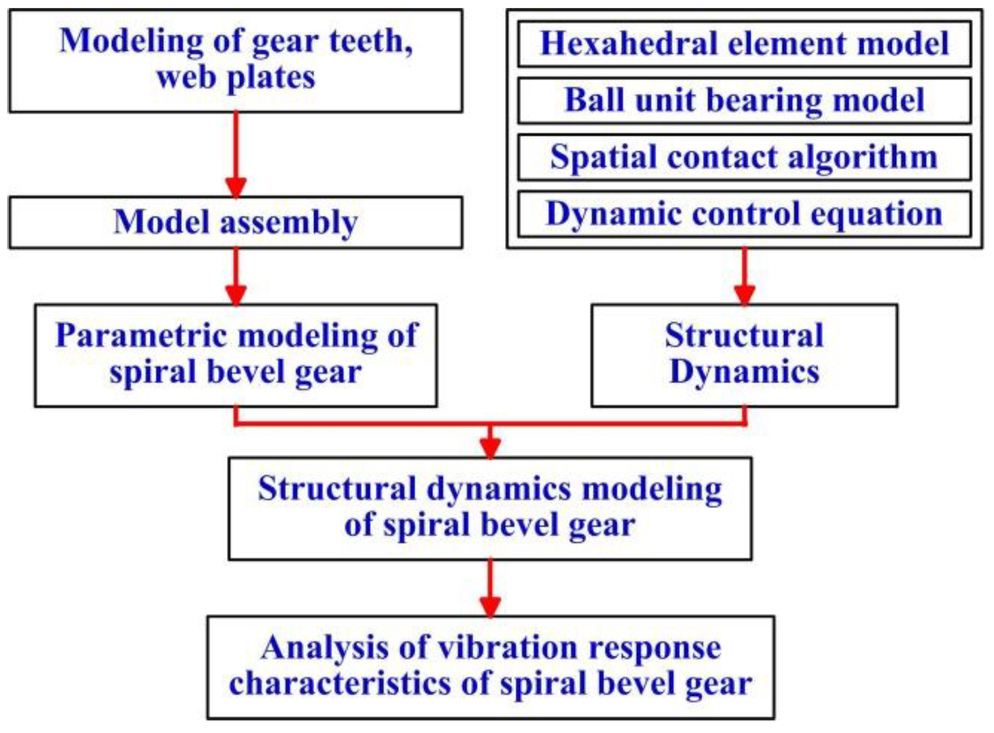
3.2. Structural Dynamics

The basic principle of structural dynamics for the SBG transmission is shown in Figure 3.
(1)
With the help of the basic theory of vector structural mechanics, a simplified calculation model of a three-dimensional (3D) hexahedron element is constructed, and the calculation expression of the hexahedron element is derived by combining the solution method of reverse motion.
(2)
Aimed at the characteristics of high-speed ball bearings in helicopter transmission systems, a ball-bearing unit model is proposed, which simplifies the bearing balls into ball units, whose position information is determined by the centre of the circle.
(3)
Drawing on the spatial contact algorithm and combining the contact behaviour characteristics of key components such as high-speed SBG transmissions and bearings, a contact calculation model is constructed. The primary-secondary algorithm is used for a global search, and internal and external algorithms are used for a local search. The spatial contact algorithm equation suitable for vector finite elements is derived.
(4)
Drawing inspiration from the meshing damping model in the theory of gear system dynamics, the relative speed of gear and pinion is used as the calculation basis for the meshing damping force to define damping and propose a variable damping model. Based on the variable damping model, the dynamic control equation is derived.
(5)
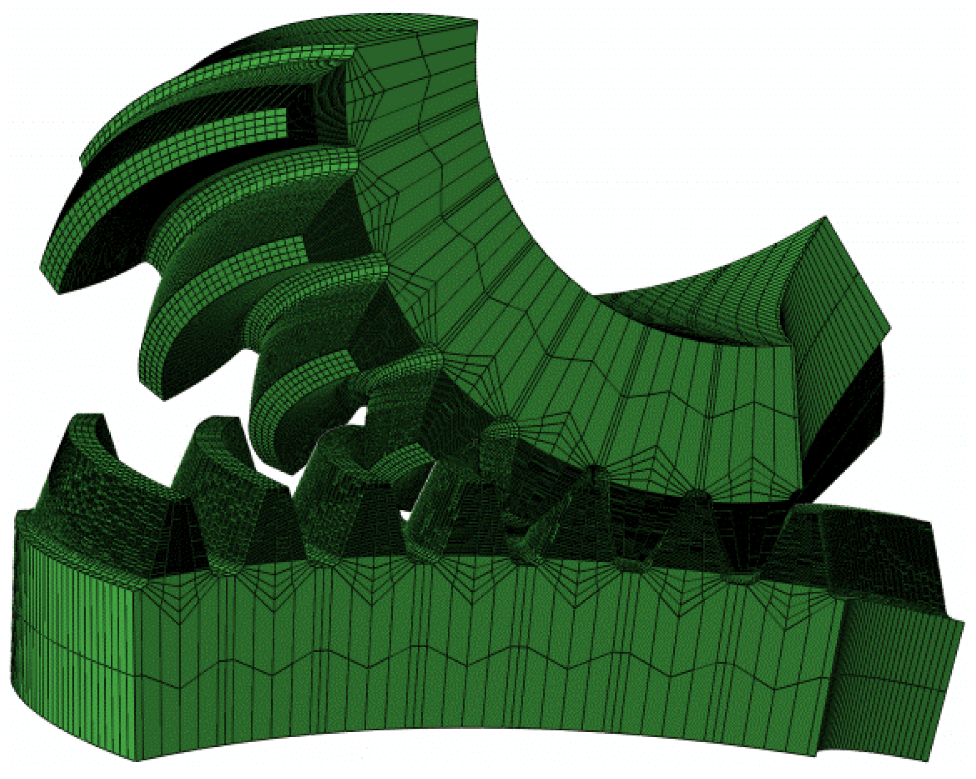
According to the machining principle of the SBG transmissions, parameterised tooth surfaces and transition surfaces are generated based on tooth surface equations with machining parameters as variables, and high-precision finite element 3D models of gear and pinion are constructed.
(6)
Based on the relative position and contact relationship between various components, the node coordinates are transformed from the local coordinate system to the assembly coordinate system, completing the assembly of the SBG transmission.
(7)
The parameterised model of SBG transmission is combined with vector dynamics to establish a model of vector dynamics of the high-speed SBG transmission system for helicopters.

3.3. Optimization Model Based on Dynamic Performance

The position vector and unit normal vector of the pinion modified tooth surface are as follows:
r 1 = r 1 ( s p , θ p , φ p , φ 1 ) n 1 = n 1 ( s p , θ p , φ p , φ 1 )
where sp and θp denote tool parameters, φp represents the angle of the shaking table, andφ1 represents the angle of the pinion.
Then, the normal deviation of discrete point i on the perfect pinion surface and the modified tooth surface is defined as:
h i ( d ) = ( p i p i ) n i ( i = 1 , 2 , , k )
where d is the pinion machining parameter. The parameters pi and ni represent the position and unit normal vectors of the pinion modified surface, respectively.
The normal deviation between the pinion modified surface and the perfect surface is as follows:
h ( d ) = [ h 1 ( d ) , h 2 ( d ) , , h k ( d ) ] T
Finally, the optimal mathematical model is created by taking the minimum sum of squares of the normal deviation, the RMA as optimization objectives and the pinion-machining parameters as optimization variables. The modified pinion surface is obtained by the following genetic algorithm:
min f 1 ( d ) = h T h min f 2 ( d ) = R a a i , b i [ χ 1 , χ 2 ]
where d are the variables. Ra represents the root mean square of the normal vibration acceleration of gear transmissions. χ1 and χ2 are the minimum and maximum variables, respectively.

4. Numerical Example

The parameters of the SBG system are shown in Table 1, Table 2 and Table 3. The load is 2300 N·m, and the input speed is 8000 rpm. Figure 4 is the normal deviation of pinion surface before and after optimization, in which the blue line and the red line represent the surface of the SBG system before and after optimization based on the active precontrol strategy of vibration, respectively. The meshing performances of the SBG system are analysed based on TCA, and shown in Figure 5, in which the red line and the blue line represent the optimized SBG system and the preset SBG system, respectively. It is found that the design contact ratio of optimized gear transmission is bigger than that of the preset gear transmission.
MS and LTE are the SBG vibration excitation sources. When the load is 2300 N·m, the LTE and MS of gears are analysed by LTCA and listed in Figure 6 and Figure 7, respectively. By comparing analyses, it can be determined that the LTE of the preset SBG transmission is 11.080″ and that the LTE of the optimized SBG transmission is 3.278″, which is 70.42% lower than that of the preset SBG transmission. The MS of the preset SBG transmission is 4.3896 × 10⁸ N/m; the MS of the optimized SBG transmission is 4.912 × 10⁸ N/m, which is 10.63% bigger than that of the preset SBG transmission; and the MS amplitude of the optimized SBG transmission is also obviously lower than the preset SBG transmission. Based on the active precontrol strategy for shape and performance, the SBG meshing qualities can be significantly improved.
To further prove the strong points of the optimized gears in MS, the MSs of gears obtained through LTCA are compared with those obtained through FEA. To ensure the accuracy of the FEA results, first of all, the accuracy of the FEA model should be guaranteed. The accuracy of the FEA model can be divided into the following two parts: tooth surface accuracy and gear assembly accuracy. To ensure tooth surface accuracy, based on the tooth surface equation, the finite element mesh model of tooth surface is built by rotating and arraying the position coordinates of discrete points of the tooth surface, and the tooth surface obtained by this method can meet the requirements of high accuracy. The solid model of the gear and the pinion is constructed with the discrete points, and then the gear and the pinion are placed in the same meshing coordinate system based on the principle of coordinate transformation to complete the assembly of the SBG system. The seven-tooth FEA model of the SBG system, shown in Figure 8, is obtained, and the assembly accuracy meets the requirements. According to the FEA model, the FEA results of gears are carried out and shown in Figure 9 and Figure 10. The comparative analysis of Figure 6 and Figure 9 reveals that the LTE amplitude obtained using the FEA method are slightly smaller than those obtained using the LTCA method, indicating that the variation of the LTE curve obtained using the two methods are basically the same. The comparative analysis of Figure 7 and Figure 10 reveals that the fluctuation amplitude of MS obtained based on FEA is comparable with those obtained based on LTCA and that the variation of the MS curve obtained using the two methods are basically the same. In conclusion, the loaded meshing performance of the optimized gear transmission is obviously improved.
The MIs of the gear pair were calculated when the input speed is 8000 rpm and load is 2300 N·m and are listed in Figure 11. Comparative studies show the impact velocity of the preset gear is 0.3495 m/s, and that of the optimized gear is 0.2593 m/s, which is 25.81% lower than that of the preset gear. The impact force of the preset gear is 3687.0 N, and that of the optimized gear is 2690.7 N, which is 27.02% lower than that of the preset gear. After optimization, the MIs of gear are reduced, and their meshing quality is also improved.
Based on the SBG dynamic model (Figure 2), the dynamic performance of gears are analysed, and their results are illustrated in Figure 12, Figure 13, Figure 14, Figure 15, Figure 16 and Figure 17. A comparative analysis found that the RMA value of the preset SBG is 851.41 m/s2, and the RMA value of the optimized gear is 196.57 m/s2, which is 76.91% lower than that of the preset gear. The dynamic load factor of the preset gear is 1.19, while that of the optimized gear is only 1.060, which is lower than that of the preset gear. It can be seen from Figure 14, Figure 15, Figure 16 and Figure 17 that the normal vibration velocity and displacement of the optimized gear transmission are considerably decreased. Therefore, based on the active precontrol strategy for shape and performance, the vibration of the SBG are reduced, and its dynamic characteristic is improved.
To further prove the strong points of the optimized gears in dynamic performance, the RMA of the gears are analysed based on the structural dynamics and shown in Figure 18. The comparative analysis of Figure 12 and Figure 18 reveals that the RMA obtained by the structural dynamics are comparable to those obtained by the lumped mass method and that the RMA curve obtained by the two methods are basically the same. In conclusion, the dynamic performance of the optimized SBG transmission is obviously improved.

5. Conclusions

The running vibration of the SBG transmission is out of control under high speed and heavy load, which shortens the time between overhauls of the main reducer of helicopters and affects the service efficiency of helicopters. For this purpose, the active precontrol strategy for shape and performance was developed for the SBG transmission so as to extend the reliable service period of helicopter.
(1)
The MS, LTE and MI are the main internal excitation sources of gears vibration. Combined with TCA, LTCA and MI theory, the MS, LTE and MI of gears are obtained. Based on lumped mass method, the dynamic model is built, and the gear dynamic performance is analysed by solving the differential equation of motion using a numerical method. An optimization model aimed at reducing the RMA of the SBG transmission is established with ease-off, and the redesigned SBG transmission with good dynamic performance is obtained through optimization.
(2)
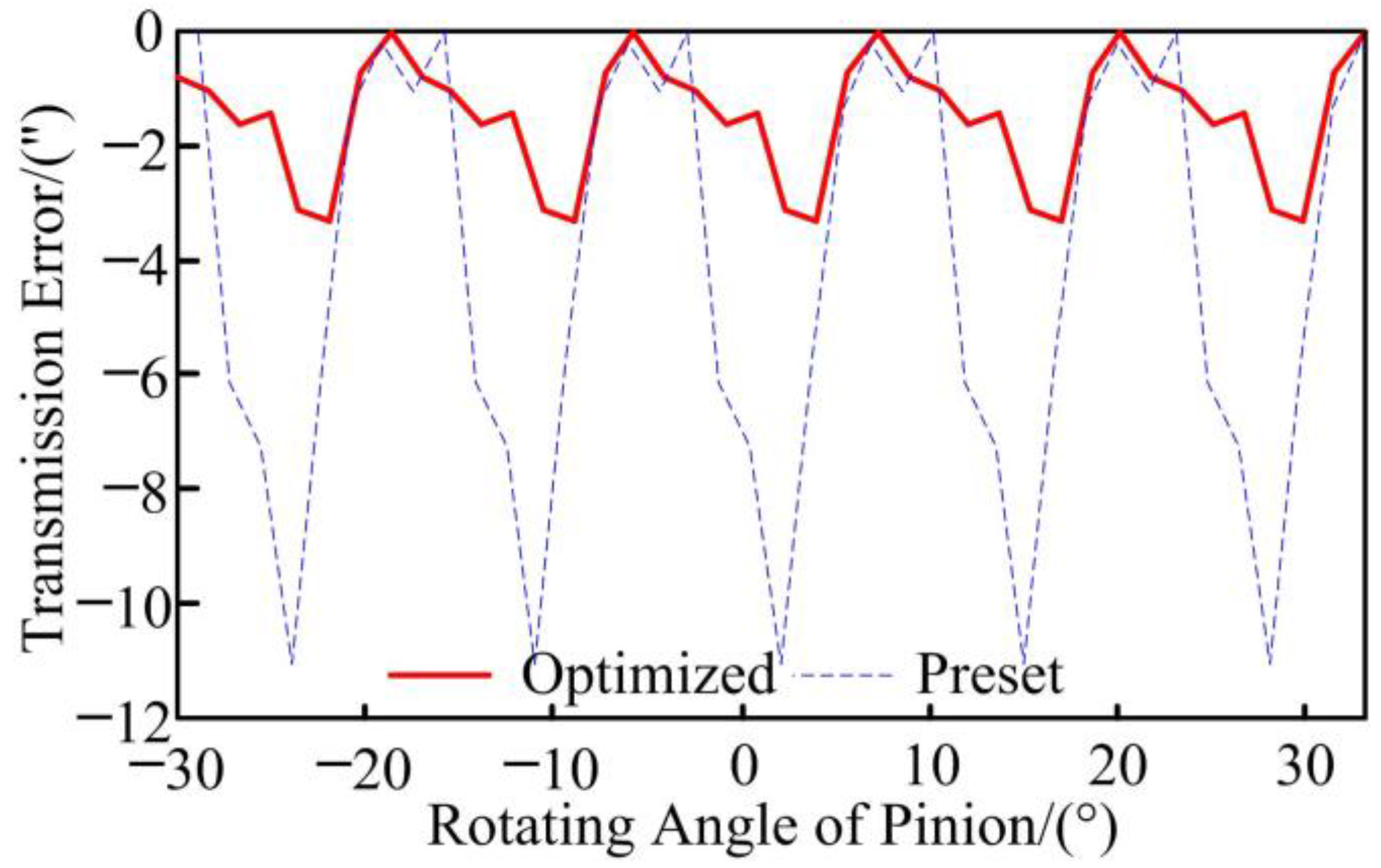
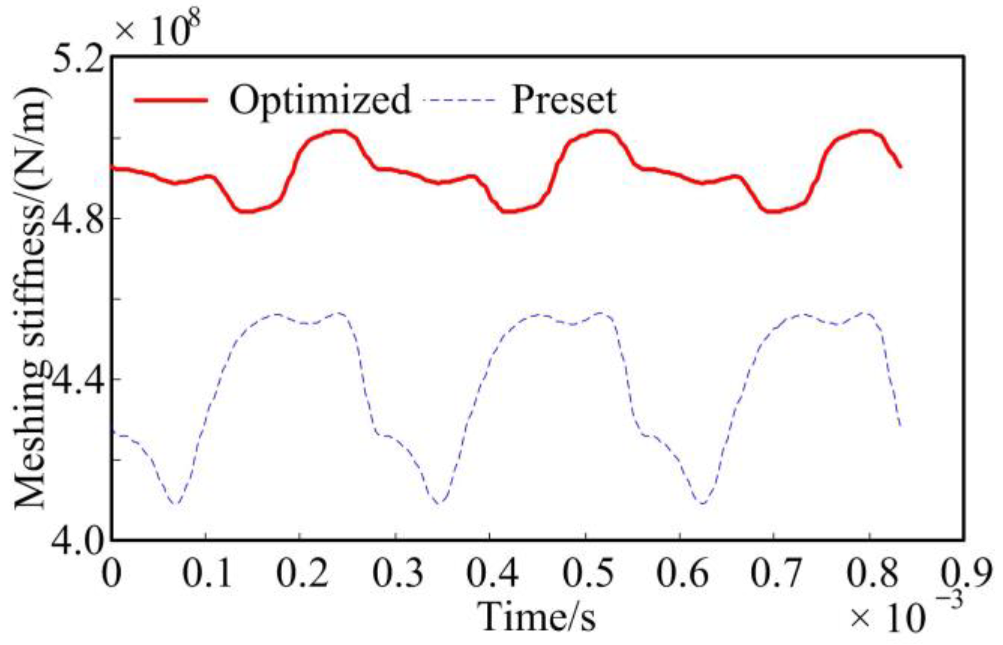
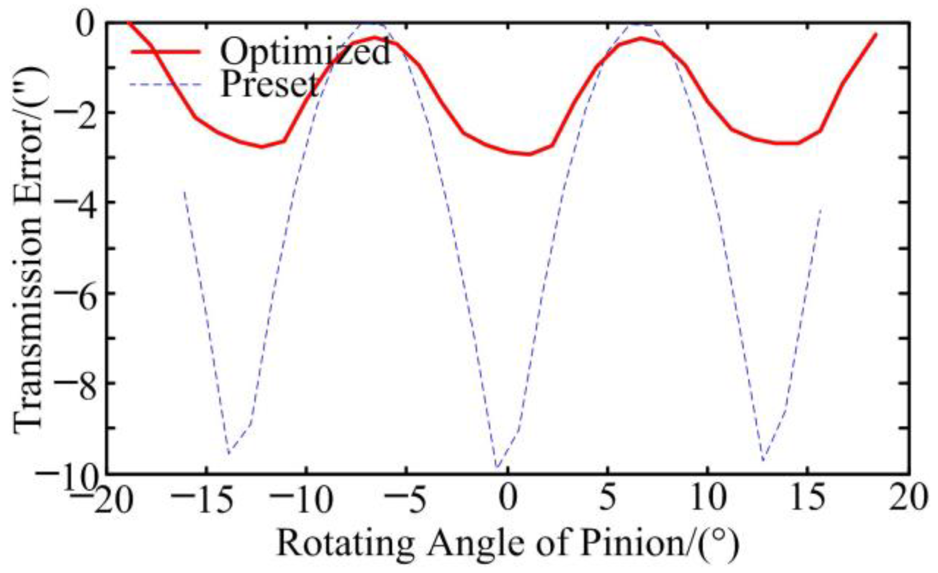
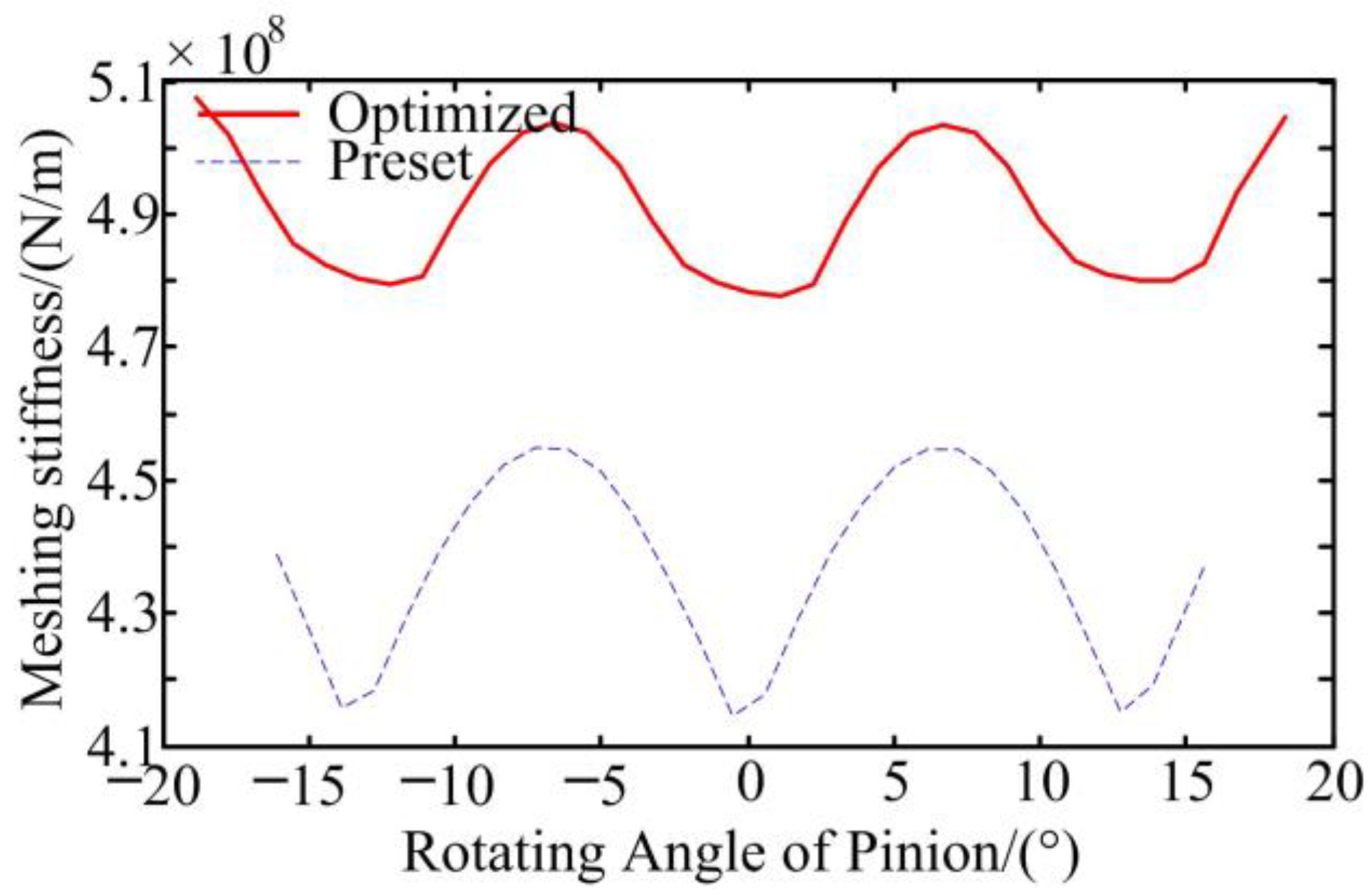
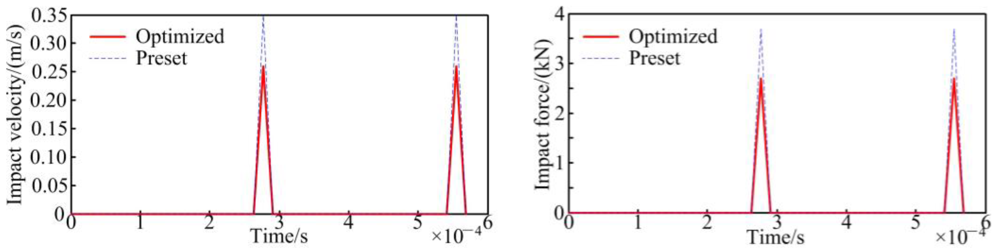
The LTCA results show that the MS and LTE amplitude of the optimized gear is significantly lower than those of the preset gear, and their accuracy has also been verified using the FEA method. The impact force and impact velocity of the optimized gear are 27.02% and 25.81% lower than the preset gear. Therefore, the meshing quality of the optimized gears is obviously improved.
(3)
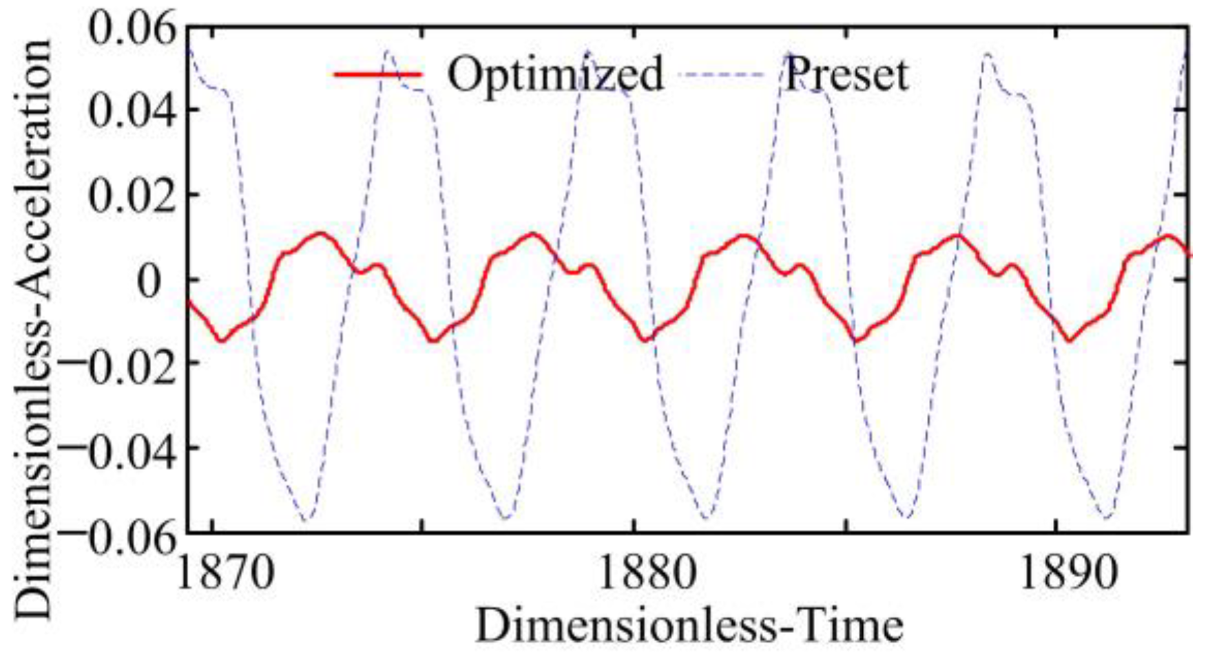
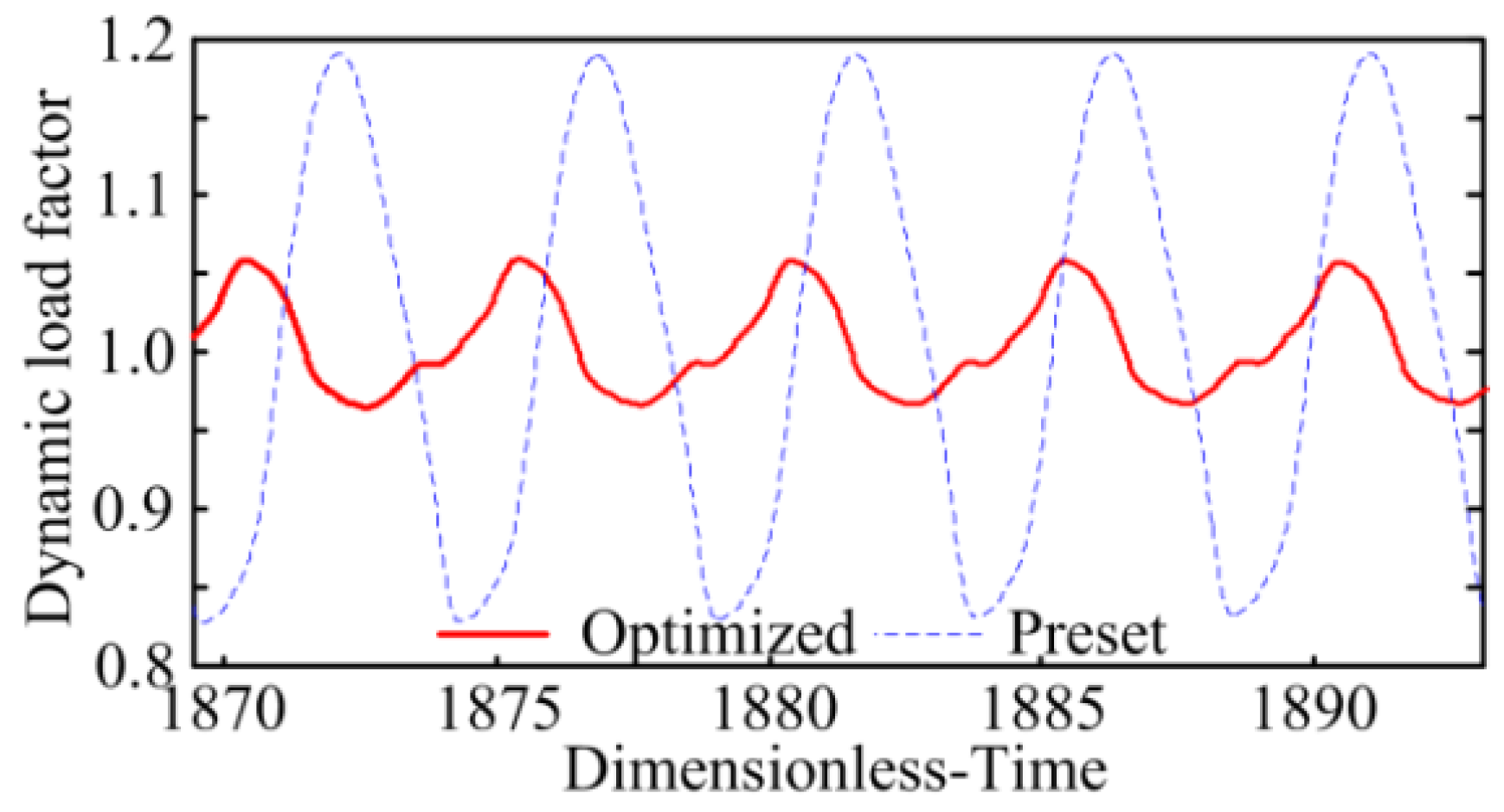
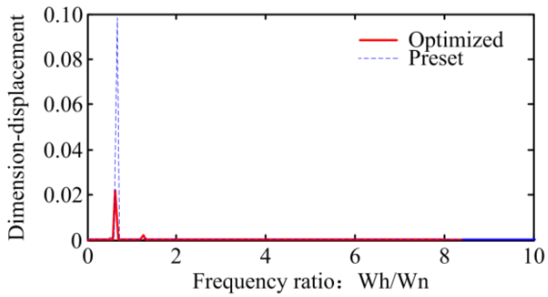
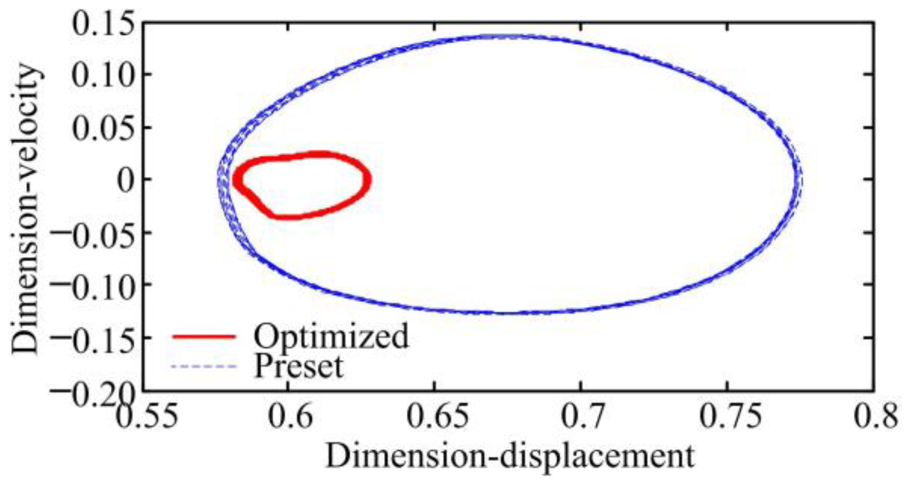
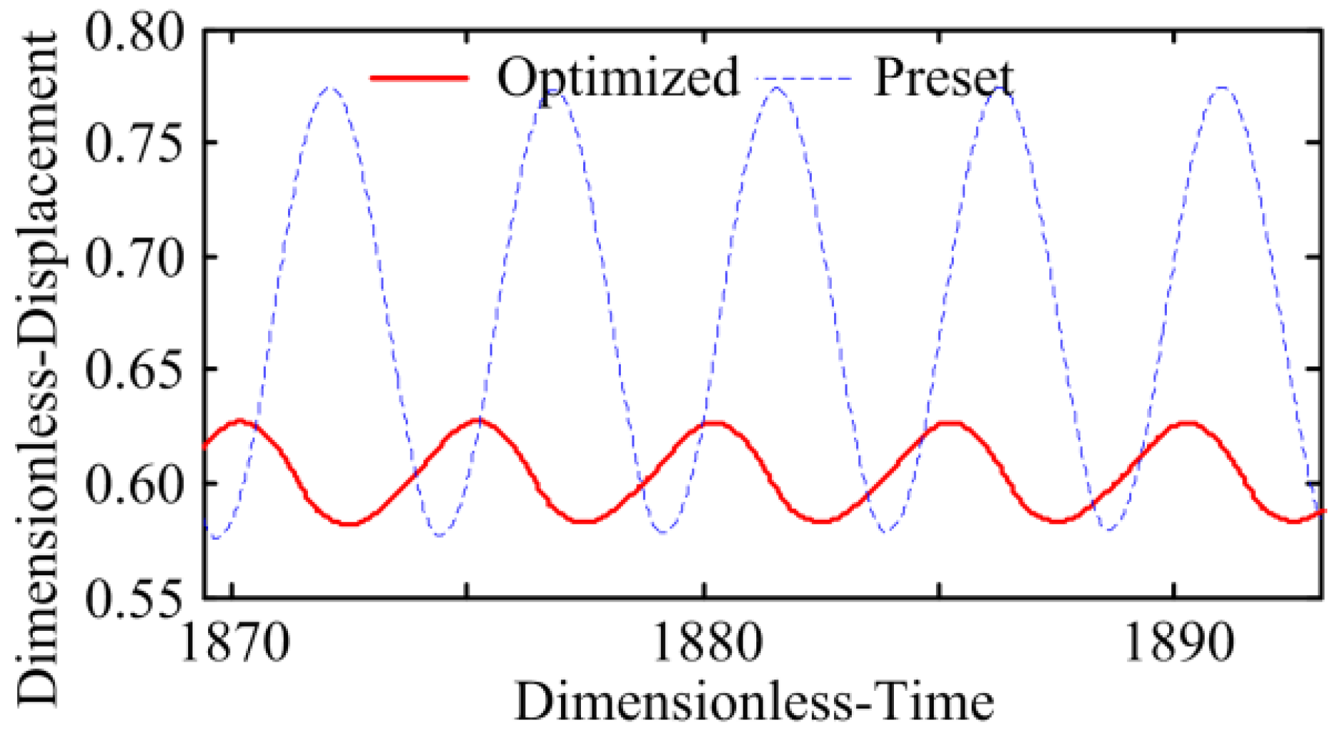
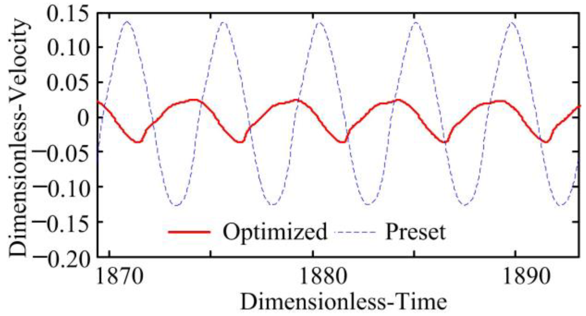
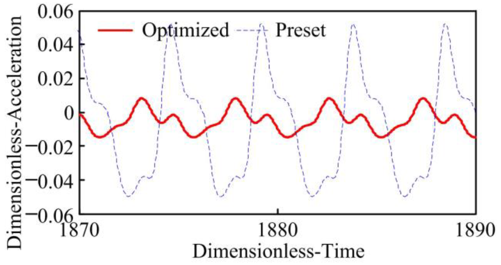
The results of dynamic analysis based on the lumped mass method show that the dynamic load factor of the optimized gears is much lower than that of the preset gear. The RMA value of the optimized gear is 76.91% lower than that of the preset gear, and they are all validated by the structural dynamics method. The normal vibration velocity and displacement of the optimized gears are obviously lower than the preset gears. Therefore, the running vibration of the gears is cut down after optimization, and their dynamic quality is improved.
Therefore, the active precontrol strategy for shape and performance can obviously improve the dynamic quality of the SBG transmissions. It can also be used for the design and analysis of other gears.

Author Contributions

Conceptualization, Y.M. and X.H. (Xiangying Hou); data curation, Y.M.; formal analysis, Y.M.; funding acquisition, Y.M. and X.H. (Xiangying Hou); methodology, Y.M. and X.H. (Xiangying Hou); resources, X.H. (Xueming He); supervision, X.H. (Xueming He); visualization, X.H. (Xueming He); writing—original draft, Y.M. and X.H. (Xiangying Hou). All authors have read and agreed to the published version of the manuscript.

Funding

The National Key Research and Development Program of China (No. 2020YFB2008100). The National Science Foundation of China (No. 52205056).

Institutional Review Board Statement

The study did not require ethical approval.

Informed Consent Statement

The study did not involve humans.

Data Availability Statement

Data is unavailable due to privacy or ethical restrictions.

Acknowledgments

We thank all reviewers and editors for their valuable comments and suggestions.

Conflicts of Interest

The authors declare no conflict of interest.

References

  1. Tang, J.Y.; Hu, Z.H.; Wu, L.J. Effect of static transmission error on dynamic responses of spiral bevel gear. J. Cent. South Univ. 2013, 22, 640–647. [Google Scholar] [CrossRef]
  2. Wang, X.; Fang, Z.D.; Mu, Y.M. Optimization design of loaded transmission error for HGT hypoid gear drives. J. Vib. Shock 2017, 36, 34–40. (In Chinese) [Google Scholar]
  3. Simon, V. Design of face-hobbed spiral bevel gears with reduced maximum tooth contact pressure and transmission errors. Chin. J. Aeronaut. 2013, 26, 21–37. [Google Scholar] [CrossRef] [Green Version]
  4. Simon, V. Optimal machine-tool settings for the manufacture of face-hobbed spiral bevel gears. ASME J. Mech. Des. 2014, 136, V005T11A001. [Google Scholar] [CrossRef]
  5. Simon, V. Manufacture of optimized face-hobbed spiral bevel gears on computer numerical control hypoid generator. J. Manuf. Sci. Eng. Trans. Asme 2014, 136, 031008. [Google Scholar] [CrossRef]
  6. Simon, V. Optimization of face-hobbed hypoid gears. Mech. Mach. Theory 2014, 77, 164–181. [Google Scholar] [CrossRef]
  7. Simon, V. Design and manufacture of spiral bevel gears with reduced transmission errors. ASME J. Mech. Des. 2015, 131, 041007–041017. [Google Scholar] [CrossRef]
  8. Simon, V. Optimal machine tool settings for face-hobbed hypoid gears manufactured on CNC hypoid generator. Int. J. Adv. Manuf. Technol. 2017, 88, 1579–1594. [Google Scholar] [CrossRef]
  9. Astoul, J.; Mermoz, E.; Sartor, M. New methodology to reduce the transmission error of the spiral bevel gears. CIRP Ann. Manuf. Technol. 2014, 63, 165–168. [Google Scholar] [CrossRef]
  10. Artoni, A.; Bracci, A.; Gabiccini, M. Optimization of the loaded contact pattern in hypoid gears by automatic topography modification. ASME J. Mech. Des. 2009, 31, 011008. [Google Scholar] [CrossRef]
  11. Artoni, A.; Kolivad, M.; Kahraman, A. An ease-off based optimization of the loaded transmission error of hypoid gears. ASME J. Mech. Des. 2011, 132, 011010. [Google Scholar] [CrossRef]
  12. Kolivand, M.; Kahraman, A. A load distribution model for hypoid gears using ease-off topography and shell theory. Mech. Mach. Theory 2009, 44, 1848–1865. [Google Scholar] [CrossRef]
  13. Kolivand, M.; Kahraman, A. An ease-off based method for loaded tooth contact analysis of hypoid gears having local and global surface deviations. ASME J. Mech. Des. 2010, 132, 071004. [Google Scholar] [CrossRef]
  14. Jiang, J.K.; Fang, Z.D.; Liu, Z. Design of multi-objective tooth optimization for hypoid gear with ease-off topological modification. J. Xi’an Jiaotong Univ. 2013, 53, 44–53. (In Chinese) [Google Scholar]
  15. Jiang, J.K.; Liu, Z.; Fang, Z.D. Optimization design of vibration reduction for hypoid gears with ease-off flank modification. J. South China Univ. Technol. Nat. Sci. Ed. 2020, 48, 138–145+152. (In Chinese) [Google Scholar]
  16. Cao, X.M.; Zhou, Y.W.; Deng, X.Z. Relationship between transmission error, contact ratio and noise of spiral bevel gear. J. Mech. Transm. 2003, 27, 43–45. (In Chinese) [Google Scholar]
  17. Kong, X.N.; Ding, H. Adaptive data-driven modeling, prediction and optimal control for loaded transmission error of helicopter zerol spiral bevel gear transmission system. Mech. Mach. Theory 2021, 165, 104417. [Google Scholar] [CrossRef]
  18. Mu, Y.M.; He, X.M.; Fang, Z.D. Wave tooth surface design of high contact ratio spiral bevel gear with minimum loaded transmission error. J. Aerosp. Power 2021, 36, 2080–2089. [Google Scholar]
  19. Yang, J.J.; Shi, Z.H. Dynamic analysis of spiral bevel and hypoid gears with high-order transmission errors. J. Sound Vib. 2018, 417, 149–164. [Google Scholar] [CrossRef]
  20. Litvin, F.L.; Cutman, Y. A method of local synthesis of gears grounded on the connection between the principal and geodetic curvatures of surfaces. ASME J. Mech. Des. 1981, 103, 114–125. [Google Scholar] [CrossRef]
  21. Litvin, F.L.; Zhang, Y. Local Synthesis and Tooth Contact Analysis of Face-Milled Spiral Bevel Gears; NASA Lewis Research Center: Chicago, IL, USA, 1991. [Google Scholar]
  22. Tian, X.B.; Fang, Z.D. Overall optimization on machine-tool settings of spiral bevel gears. J. Aerosp. Power 2000, 15, 75–77. (In Chinese) [Google Scholar]
  23. Shih, Y.P. A novel ease-off flank modification methodology for spiral bevel and hypoid gears. Mech. Mach. Theory 2010, 45, 1108–1124. [Google Scholar] [CrossRef]
  24. Shih, Y.P.; Chen, S.D. A flank correction methodology for a five-axis CNC gear profile grinding machine. Mech. Mach. Theory 2012, 47, 31–45. [Google Scholar] [CrossRef]
  25. Su, J.Z.; He, Z.X. High-precision modification of tooth surface for spiral bevel gears. J. South China Univ. Technol. Nat. Sci. Ed. 2014, 42, 91–96. (In Chinese) [Google Scholar]
  26. Artoni, A.; Gabiccini, M. Multi-objective ease-off optimization of hypoid gears for their efficiency, noise, and durability performances. ASME J. Mech. Des. 2010, 133, 267–277. [Google Scholar]
  27. Artoni, A.; Gabiccini, M. Ease-off based compensation of tooth surface deviations for spiral bevel and hypoid gears: Only the pinion needs corrections. Mech. Mach. Theory 2012, 61, 1108–1124. [Google Scholar] [CrossRef]
  28. Wei, B.Y.; Li, J.Q. Calculation of gear mesh stiffness and loaded tooth contact analysis based on ease-off surface topology. Adv. Mech. Eng. 2022, 14, 16878132221133979. [Google Scholar] [CrossRef]
  29. Chen, P.; Wang, S.M.; Li, F. A direct preset method for solving ease-off tooth surface of spiral bevel gear. Mech. Mach. Theory 2022, 179, 105123. [Google Scholar] [CrossRef]
  30. Peng, X.L.; Zhang, L. Manufacturing process for a face gear drive with local bearing contact and controllable unloaded meshing performance based on ease-off surface modification. J. Mech. Des. 2016, 138, 043302. [Google Scholar] [CrossRef]
  31. Wang, Q.; Zhou, C. An ease-off based approach to designing a high-order transmission motion for face-milled spiral bevel gears. Int. J. Veh. Des. 2019, 81, 241–264. [Google Scholar] [CrossRef]
  32. Mu, Y.M.; He, X.M.; Fang, Z.D. Design and dynamic performance analysis of high-contact-ratio spiral bevel gear based on ease-off technology. Int. J. Precis. Eng. Manuf. 2021, 22, 1963–1973. [Google Scholar] [CrossRef]
  33. Mu, Y.M.; He, X.M.; Fang, Z.D. An innovative ease-off flank modification method based on the dynamic performance for high-speed spiral bevel gear with high-contact-ratio. Mech. Mach. Theory 2021, 162, 104345. [Google Scholar] [CrossRef]
  34. Wang, Q.; Jiang, J.K. Design and analysis for hypoid gears with ease-off flank modification. Appl. Sci. 2022, 12, 822. [Google Scholar] [CrossRef]
  35. Li, G.; Zhu, W.D. An active ease-off topography modification approach for hypoid pinions based on a modified error sensitivity analysis method. J. Mech. Des. 2019, 141, 093302141. [Google Scholar] [CrossRef]
  36. Mu, Y.M.; He, X.M.; Fang, Z.D. Multiobjective ease-off optimization of high-speed spiral bevel gear for loaded meshing performance. J. Braz. Soc. Mech. Sci. Eng. 2021, 43, 382. [Google Scholar] [CrossRef]
  37. Ting, E.C.; Shih, C.; Wang, Y.K. Fundamentals of a vector form intrinsic finite element: Part II. Plane solid elements. J. Mech. 2004, 20, 123–132. [Google Scholar] [CrossRef]
  38. Hou, X.Y.; Fang, Z.D.; Zhang, X.J. Static contact analysis of spiral bevel gear based on modified VFIFE (vector form intrinsic finite element) method. Appl. Math. Model. 2018, 60, 192–207. [Google Scholar] [CrossRef]
  39. Su, J.Z.; Fang, Z.D.; He, Z.X. Study on dynamic of spiral bevel gears based on meshing characteristics. Mech. Sci. Technol. Aerosp. Eng. 2016, 35, 50–55. [Google Scholar]
  40. Mu, Y.M.; Fang, Z.D.; Li, W.L. Impact analysis and vibration reduction design of spiral bevel gears. Proc. Inst. Mech. Eng. Part K J. Multi Body Dyn. 2019, 233, 668–676. [Google Scholar] [CrossRef]
Figure 1. The perfect surface.
Applsci 13 08527 g001
Figure 2. Dynamic model of the SBG transmission.
Applsci 13 08527 g002
Figure 3. The basic principle of structural dynamics.
Applsci 13 08527 g003
Figure 4. The normal deviation of tooth surface.
Applsci 13 08527 g004
Figure 5. The TCA results.
Applsci 13 08527 g005
Figure 6. The LTE of gears based on LTCA.
Applsci 13 08527 g006
Figure 7. The MS of gears based on LTCA.
Applsci 13 08527 g007
Figure 8. The FEA model of the SBG system.
Applsci 13 08527 g008
Figure 9. The LTE of gears based on FEA.
Applsci 13 08527 g009
Figure 10. The MS of gears based on FEA.
Applsci 13 08527 g010
Figure 11. MI of gear before and after optimization.
Applsci 13 08527 g011
Figure 12. Vibration acceleration with lumped mass method.
Applsci 13 08527 g012
Figure 13. Dynamic load factor with lumped mass method.
Applsci 13 08527 g013
Figure 14. Dimensionless displacement with lumped mass method.
Applsci 13 08527 g014
Figure 15. Normal vibration phase diagram with lumped mass method.
Applsci 13 08527 g015
Figure 16. Vibration displacement with lumped mass method.
Applsci 13 08527 g016
Figure 17. Vibration velocity with lumped mass method.
Applsci 13 08527 g017
Figure 18. Vibration acceleration with structural dynamics.
Applsci 13 08527 g018
Table 1. Gear parameters.
ParameterPinionGear
Number of teeth2774
Module/mm3.85
Pressure angle/(°)20
Mean spiral angle/(°)30
Hand of spiralLHRH
Shaft angle/(°)87
Face width/mm40
Table 2. Processing parameters of gear.
ParameterGear
Radial setting/mm119.687
Initial cradle angle setting/(°)−43.568
Roll ratio1.084
Vertical offset/mm0
Increment of machine centre to back/mm0
Sliding base feed setting/mm−1.741
Machine root angle/(°)66.005
Table 3. Processing parameters of pinion.
ParameterPresetOptimized
Radial setting/mm115.269113.106
Initial cradle angle setting/(°)43.53543.111
Roll ratio2.8842.834
Vertical offset/mm−3.584−5.580
Increment of machine centre to back/mm−2.063−3.226
Sliding base feed setting/mm0.0700.446
Machine root angle/(°)18.89718.897
Second-order coefficients0.0590.039
Third-order coefficients0.0030.019
Disclaimer/Publisher’s Note: The statements, opinions and data contained in all publications are solely those of the individual author(s) and contributor(s) and not of MDPI and/or the editor(s). MDPI and/or the editor(s) disclaim responsibility for any injury to people or property resulting from any ideas, methods, instructions or products referred to in the content.

