Article

Compressive Behavior of a Novel Hexagonal Nodes-Based 3D Chiral Auxetic Structure

1
School of Architecture and Civil Engineering, Shenyang University of Technology, Shenyang 110870, China
2
Multidisciplinary Center for Infrastructure Engineering, Shenyang University of Technology, Shenyang 110870, China
3
Liaoning Provincial Key Laboratory of Infrastructure Engineering Safety and Protection, Shenyang University of Technology, Shenyang 110870, China
4
College of Aerospace and Civil Engineering, Harbin Engineering University, Harbin 150001, China
*
Author to whom correspondence should be addressed.
Appl. Sci. 2023, 13(14), 8480; https://doi.org/10.3390/app13148480
Submission received: 16 June 2023 / Revised: 17 July 2023 / Accepted: 20 July 2023 / Published: 22 July 2023

Abstract

:
The energy absorption capacity of materials with negative Poisson’s ratio (NPR) is attracting interest from both industry and academia due to the excellent impact resistance of the local shrinkage of materials. However, understanding the compressive behavior of 3D auxetic structures at different strain rates and developing design methods are challenging tasks due to the limited literature and insufficient data. This paper presents a study on the behavior of Poisson’s ratio of an advanced 3D chiral structure, which is formed of two orthogonally positioned 2D hexagonal nodes-based chiral structures. Firstly, both theoretical analysis and numerical simulations are conducted to identify the Poisson’s ratio of 2D chiral structures. The same theoretical value of −1 is obtained for 2D chiral structures with a bending-dominated ligaments assumption. Thereafter, the Poisson’s ratio of 3D chiral structures is determined numerically using a low-speed loaded model composed of 5 × 5 × 8 3D unit cells for eliminating the boundary effects. The results show that impact velocity can strongly affect the energy absorption and deformation behavior of the proposed 3D chiral structure. Increasing the beam radius results in reduced energy absorption capability. However, the energy absorption capability of the 3D chiral structure is not sensitive to the yield strength of nodes. Impact direction affects the energy absorption performance of the 3D chiral structure, depending on the crushing strain. The research results could be used to optimize the design of the proposed novel 3D chiral honeycombs for various applications, such as impact energy absorbers and vibration-resistant dampers.

1. Introduction

Cellular structures provide engineers and researchers with the possibilities of applying lightweight and high-energy absorption structures in sophisticated industries, such as the automotive, aerospace and shipbuilding industry. When the metal foams or honeycomb structures undergo compressive loading, the stress–strain curve usually experiences a long stress plateau before the densification. This is highly advantageous for applications as an energy absorber. The impact kinetic energy is effectively dissipated by transforming it into plastic strain energy with structural deformation. The successful utilization of cellular structures as protective shields in impact mitigation has drawn a lot of attention [1,2,3]. Apart from direct applications of cellular structures, they have been widely used as core structures of sandwich panels, which present a combination of high strength to weight ratio and excellent energy absorption capacity [4,5]. Meanwhile, the concept of cellular structures filled with thin-wall composite structures has been proved to be effective in improving the energy absorption capacity [6,7,8]. Motivated by the potential enhancement in impact resistance, cellular structures possessing negative Poisson’s ratio (NPR) have attracted considerable interest in the past few decades.
The structures deform with the NPR effect, also known as auxetic structures or auxetics, shrink in the transverse direction when compressed in the longitudinal direction, and vice versa. Specifically, the shrinkage effect can densify the local material in the vicinity of the impact zone and further improve the impact resistance [9]. For isotropic and elastic materials, strain energy should satisfy the non-negativity requirement. Poisson’s ratio can theoretically occur in a range between −1 and 1/2 [10]. The existence of auxetic materials in the natural world was doubtful until Love [11] reported the NPR behavior of iron pyrite. To date, there are a number (more than 20 types) of natural materials and structures known to be auxetic and observed, for example, in the skin of mammals, certain forms of bone and crystalline solids [12,13,14,15]. However, the naturally occurring auxetic materials are difficult to apply practically in protection engineering because of the lack of available candidate materials. Typically, technologies and measures, such as laser cutting, welding and water-jet cutting, are commonly applied in manufacturing two-dimensional (2D) auxetics [16,17,18], while manufacturing processes, such as artificial synthesis and three-dimensional (3D) printing, have usually been used for creating 3D auxetics [19,20,21]. In addition, 3D auxetics are also conceptualized from their 2D substructures.
Regarding the in-plane impact performance of 2D auxetic structures, re-entrant honeycomb has been discussed the most. Wu et al. [22] proposed a graded design of 2D re-entrant honeycomb by changing the cell wall angle along the crushing direction. Then, they numerically investigated the effectiveness of the angle-graded design in the enhancement of structural energy absorption capacity. They identified that the re-entrant honeycomb with angle-graded design absorbed more energy when subjected to quasi-static or low-speed impact loading. However, this enhanced energy absorption capacity could only happen to certain impact direction as increasing impact speed. In order to compare the impact performance between re-entrant honeycomb and hexagonal honeycomb, Liu et al. [23] carried out a numerical study with the consideration of various values of crushing velocity. The results revealed that re-entrant honeycomb was superior in plastic energy absorption to conventional hexagonal honeycomb, which, however, exhibited lower peak stress at the same dissipated plastic energy. A similar conclusion was drawn by Ingrole et al. [24] through an experimental and numerical investigation. Zhou et al. [25] and Yu et al. [17] carried out experimental and numerical studies on the impact behavior of aluminum re-entrant honeycombs filled by concrete foam and polyurethane (PUR) foam, respectively. Enhanced energy absorption capacity was identified. In addition to re-entrant auxetic honeycombs, Gao et al. [26] carried out a theoretical and numerical study on the in-plane impact behavior of chiral honeycomb. The theoretical solution of yield stress at quasi-static loading was analyzed. Chiral honeycomb showed inapparent peak stress under both low-speed and high-speed impact when compared to conventional hexagonal honeycomb, although the conventional honeycomb exhibited better performance in plastic energy absorption. Airoldi et al. [27] experimentally and numerically investigated the in-plane local impact resistance of foam-filled chiral composite structures. The participation of foam could further enhance the energy absorption capacity of the chiral structure. Xu et al. [28] first produced a new type of cementitious auxetic structure via 3D-printing technologies. High specific energy absorption and 2.5% reversible deformation were observed. In the last decade, there has been growing interest in the study of 2D auxetic structures. To the authors’ knowledge, however, the application of 2D auxetic structures in practical engineering for impact protection is currently lacking.
Regarding the mechanical properties of 3D auxetic structures, relatively few studies have explored the dynamic compressive behavior. Imbalzano et al. [29] performed a numerical study on the blast resistance of a sandwich composite structure with a 3D re-entrant honeycomb core. Maximum 70% and 30% reductions in velocity and displacement at the back were, in fact, obtained when compared with an equivalent monolithic panel. Logakannan et al. [30] experimentally and numerically investigated the dynamic performance of a 3D re-entrant honeycomb, considering the effects of structural geometric parameters and impact velocity. Enhanced energy absorption capacity compared to its 2D structure was confirmed beyond a certain strain. Mohsenizadeh et al. [31] proposed a fabrication process for re-entrant foam. Afterwards, the crashworthiness evaluation of an auxetic foam-filled tube under quasi-static axial loading was investigated through experimental tests and numerical simulations. The superiority of the re-entrant foam-filled square tube was confirmed in terms of all defined crashworthiness parameters when compared to empty and conventional foam-filled square tubes. Although several types of 3D chiral structures [32,33,34,35,36] have been proposed, the investigations have generally limited on the quasi-static mechanical properties in elastic deformation or dynamic response at low strain rate.
Since the above studies on 3D auxetic structures are among the first on this topic, most of them are limited in elastic scope, and the main research objectives are 3D re-entrant structures. With the development of 3D printing, nowadays, 3D auxetic structures can be fabricated easily. Thus, the mechanical properties of various 3D auxetic structures deserve consideration. To the best of the authors’ knowledge, there has been no study on the failure behavior and energy absorption of 3D hexagonal chiral structures under compressive loadings. Consequently, there are insufficient data to develop a comprehensive understanding of the effects of various parameters on compressive behavior for the development of design methods in practical engineering.
To address the limitations mentioned above, following the authors’ prior study on the 2D chiral auxetic structure, this study aims to investigate the compressive response of the novel 3D chiral auxetic structure with the aid of ABAQUS/Explicit. The novel 3D chiral auxetic is designed by orthogonally assembling two 2D chiral auxetics but replacing the circular nodes-based conventional chiral auxetics (ACs) with hexagonal nodes-based chiral auxetics (AHs). Firstly, the FE models were validated against the literature experimental data. Then, the in-plane Poisson’s ratio of 2D AH was measured numerically. Afterwards, the behavior of 3D AHs under compressive loading was simulated in terms of failure mode, stress–strain response and energy dissipation, with special focus on the effects of strain rate, beam radius and node yield strength, impact direction and impact mass. Finally, based on the simulations, the underlying mechanisms of dynamic compressive behavior of 3D chiral auxetic structures were discussed in depth.

2. Geometric Design

Since being proposed and theoretically investigated by Prall and Lakes [37], in-plane mechanical properties and practical applications of chiral structure have attracted a lot of interest. According to the original demonstration based on the ligament bending theory, the chiral structure exhibits an in-plane NPR of −1 in two orthogonal directions. In order to extend the in-plane NPR effect of the chiral structure to be spatial, two in-plane chiral unit cells are positioned orthogonally, as presented in Figure 1. Ligament-1 and Ligament-2 intersect each other, and they form a common midpoint for the two ligaments. It should be pointed out that the circular nodes of conventional chiral auxetics (ACs) are replaced with hexagonal nodes (Figure 2) so as to simplify the pre-processing of FE simulations and effectively avoid the initial penetration between each adjacent node and ligament. The side length of the hexagonal node is kept the same as the radius of the previous circular node. The geometric relation θ = 30° remains for hexagonal nodes-based chiral auxetics (AHs), but the geometric parameter β is determined by the following relation since the ligaments do not need to be tangential to the nodes:
cos β = R 2 + L 2 4 r 2 2 R L
Referring to the definition of relative density for 2D AC by Spadoni and Ruzzene [26], the relative density of 3D AHs can be defined as the ratio of the volume occupied by the unit cell to the whole unit cell involved in 3D space. Then, for a 3D AH, which is structured by circular cross-section members with a radius of rAH, the relative density is calculated as
ρ ¯ = 12 π r A H 2 r + 6 L π r A H 2 R 3 cos 2 θ

3. Poisson’s Ratio

3.1. Poisson’s Ratio of 2D AH

Before going ahead with the 3D model, the 2D AH, as shown in Figure 2, is simulated in ABAQUS 6.14 to identify the in-plane Poisson’s ratio in two directions. According to the original research revealed in [37], the ultimate orthogonal strains in both X and Y directions are ε X = ε Y = ϕ r / R , where ϕ is the angular deflection induced by the rotation of nodes. The shapes of nodes have no influence on the Poisson’s ratio of chiral auxetics since ϕ = ϕ , which is illustrated in Figure 2. Later on, Spadoni and Ruzzene [38] refined the estimation of elasto-static behavior of chiral structures considering the axial and shear deformations of ligaments, and they found that the expression of Poisson’s ratio is υ m = 4 ( t / L ) 2 ( t / L ) 4 cos 2 β + 1 cos 2 β + 3 ( t / L ) 2 1 , where t is the wall thickness of nodes and ligaments. Incorporating with Equation (1), the following equation (Equation (3)) is obtained. Then, it can be seen from above that the parameter L determines the different Poisson’s ratio between AC and AH when replacing the circular nodes with hexagonal ones.
υ m = 4 t 2 L 2 L 2 4 r 2 + R 2 2 4 L 2 R 2 + 3 t 2 L 2 + t 4 L 2 4 r 2 + R 2 2 4 L 6 R 2 + 1 1
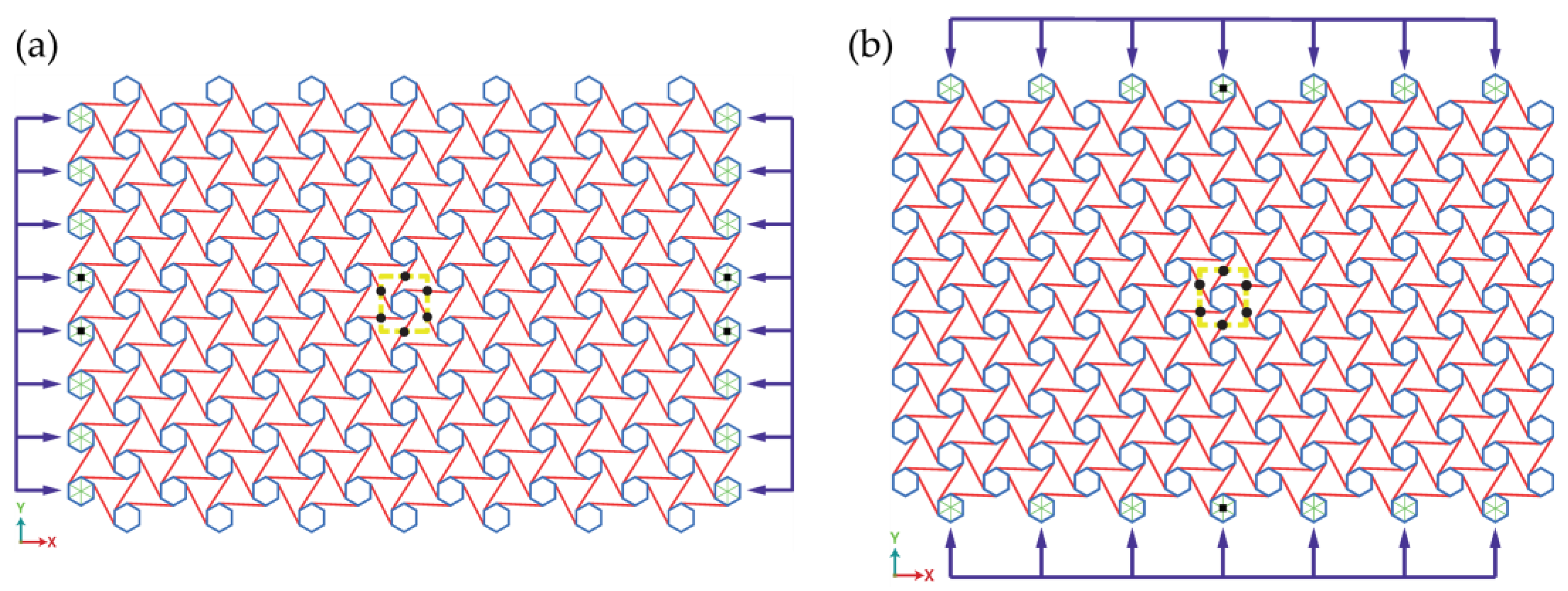
The FE model of 2D AH is set up with a geometric topology L/R = 0.85, and the value of L is initially set to 100 mm. The nodes and ligaments are modelled with 2-node linear Timoshenko beam elements (B31), and they share the same beam section profile of circular shape with a radius of 0.5 mm. The 2D AH is discretized with an element size of 5 mm. For the purpose of mimicking the ligament-bending-dominated deformation assumption considered by Prall and Lakes [37], Young’s modulus of nodes is ten-times the one of the ligaments, as recommended by Hassan and Scarpa [39]. The boundary conditions of 2D AH, as depicted in Figure 3a,b, are defined as below: only in-plane deformations are allowed for the whole model; displacement boundary conditions are applied at the center of each side node in either the X or Y direction, and nodes are constrained to be rigid. In order to eliminate rigid displacements, nodes on the loaded side are limited to travel along the loaded direction. The Poisson’s ratio of 2D AH is obtained by measuring the shrinkage of the yellow rectangle, the sides of which pass through the half of ligaments embracing the central node of the model.
In addition, force−displacement curves obtained from the explicit model developed using shell elements in ABAQUS were also assessed against the results of the experimental test, which was conducted in the laboratory. The specimens of chiral structure were manufactured via 3D printing, with a dimension of 140.8 × 124.5 mm2 in plane and 15 mm in depth. The geometric topology of test specimens has an L/R of 0.85, L of 30 mm and wall thickness of 2 mm. The material used for 3D printing is DSM’s Somos®14120, which has an elastic modulus of 2460 MPa, Poisson’s ratio of 0.23 and tensile strength of 45 MPa. The MTS universal testing machine was used for the tests, with a compressive speed of 0.1 mm/s. The capability of FE models to capture the failure modes and stress–strain response of 3D auxetic structures is validated with the available experimental tests in the literature for 3D re-entrant lattices [30]. The specimen has a dimension of 65 × 65 × 56 mm3 and a compressive velocity of 5 m/s.
Figure 4 plots the compression forces–deformations curves for both the numerical simulation and experimental test. Good agreements are observed throughout, which shows that both the 2D and 3D explicit dynamic models used in the present study are effective and reasonable. In Figure 4a, the lower initial stiffness in the experimental test than that in the simulation may be attributed to the initial space between the specimen and the load cell. In addition, the uneven surface and irregular shape of the specimens from the fabrication errors may also cause this. Figure 5 plots the variation in Poisson’s ratio at different compression strains, and it is observed that the Poisson’s ratios (νxy and νyx) of 2D AHs almost remain constant and approach a theoretical value of −1, as obtained in 2D ACs. This can be easily explained from Equation (3) that switching L from tangent length (100 mm) to extremity length (101.9 mm) brings about a negligible influence on υ m .

3.2. Poisson’s Ratio of 3D AH

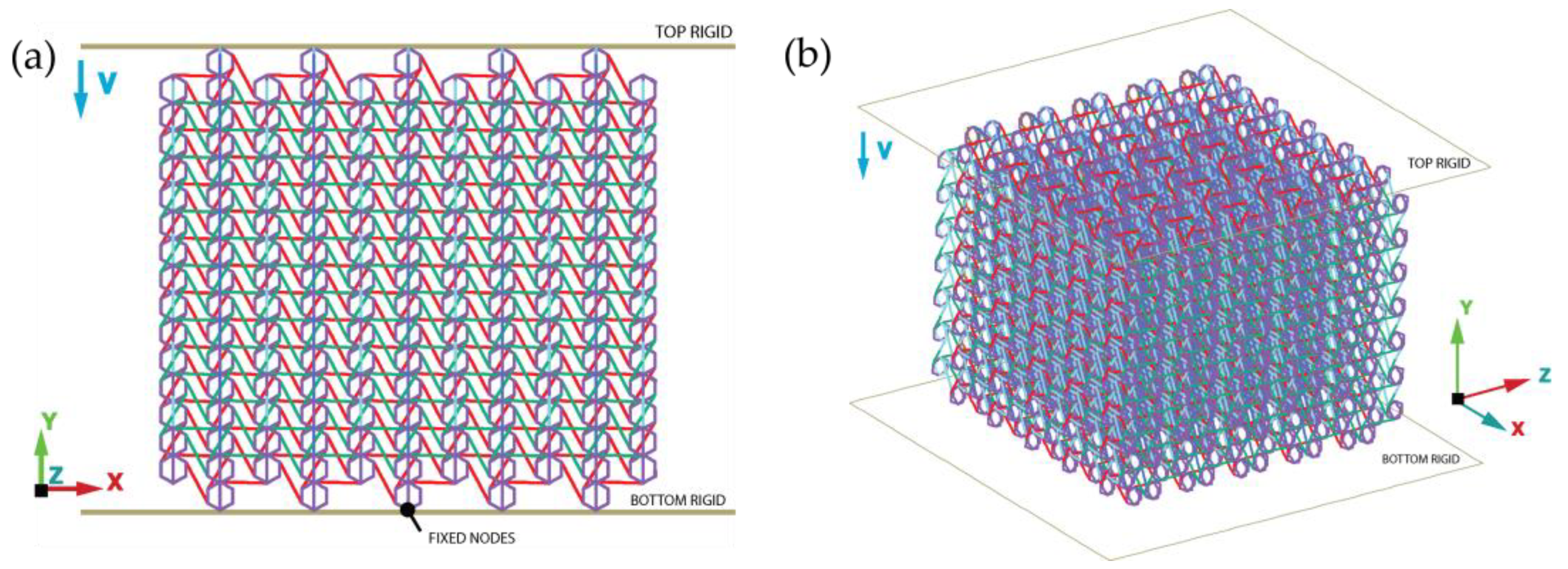
The Poisson’s ratio of 3D AH, as presented in Figure 6, is confirmed numerically considering a geometric topology of L/R = 0.85 and L = 50 mm. The same type of beam elements (B31) used for modelling 2D AH is adopted herein to simulate the dynamic crushing process of 3D AH, which has a circular cross-section of radius equal to 0.5 mm. The elastic-ideally plastic material model is adopted with a Young’s modulus (E) of 70 GPa, yield stress (σY) of 130 MPa, Poisson’s ratio (ν) of 0.3 and density (ρ) of 2.7g/cm3 to represent the material properties of aluminum. There are 5 × 5 × 8 3D unit cells involved in the 3D AH model with a dimension of 536.26 × 536.26 × 505.57 mm3. The 3D AH is sandwiched between two rigid plates, namely the top rigid (plate) and the bottom rigid (plate), which are constrained to travel along the unique direction (-Y) and fixed at the reference node, respectively. In addition, a set of central nodes at the bottom of 3D AH are fixed as well to eliminate the rigid displacements. The “General Contact” is used to consider all possible contact interactions during the crushing processes, and no friction is considered in the present study. The accuracy of the numerical model is verified through a mesh convergence study. It turns out that discretizing the whole model with 5 mm length B31 is reasonable to evaluate the dynamic performance of 3D AH, as shown in Figure 7. In comparison with the crushing force and plastic energy dissipation, the B31 model agrees very well with the B32 (3-node quadratic Timoshenko beam elements) model, but the B31 model is more time-efficient with the same mesh control as that of the B32 model.
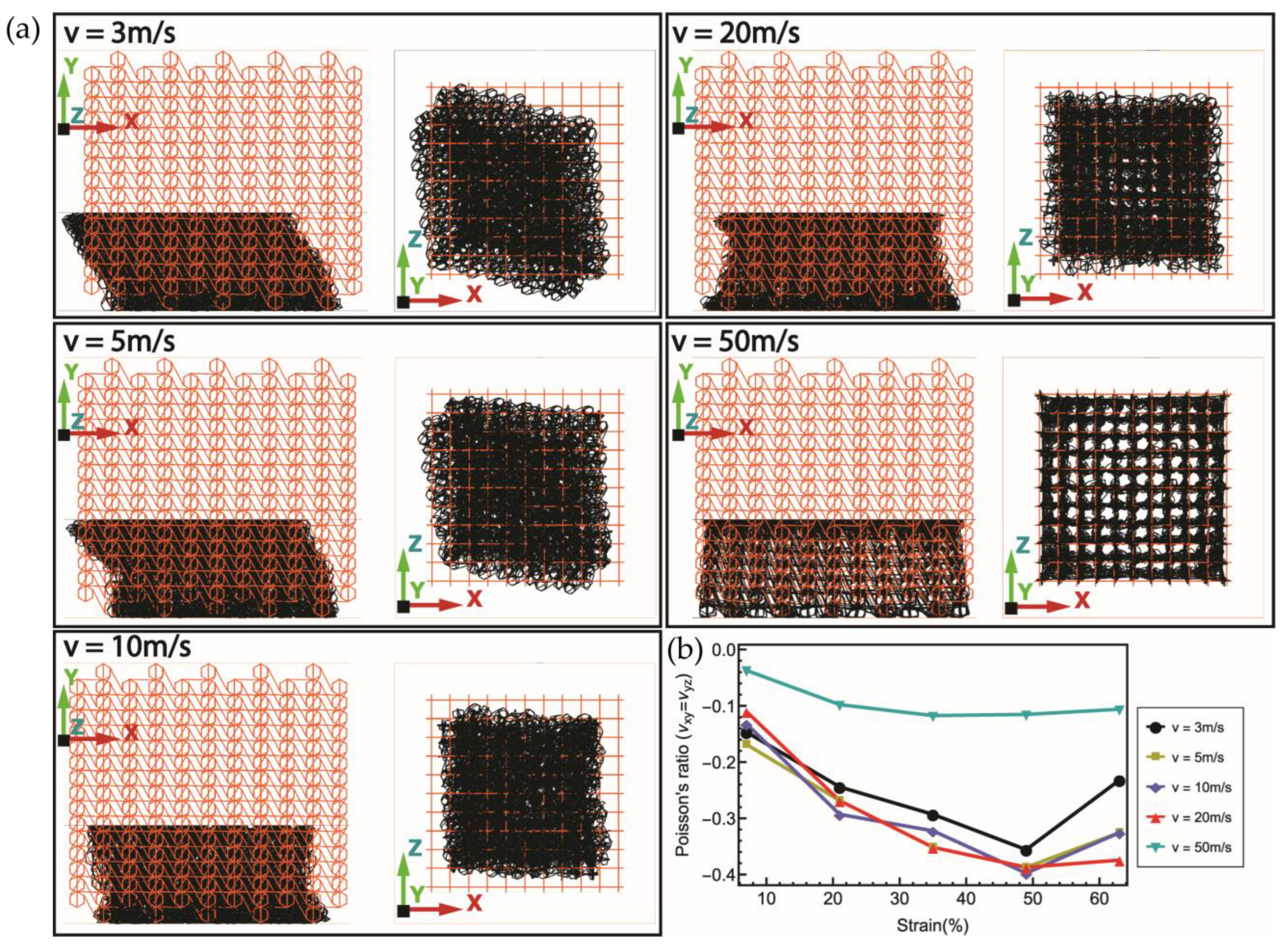
Figure 8a shows the Poisson’s ratio (PR) behavior of 3D AHs subjected to various impact velocities. Almost the same magnitude of Poisson’s ratios ( υ xz and υ zx ) is observed when the 3D AH is loaded along the Y direction up to a crushing strain of 63%. Following the increase in crushing strain, the original orthogonally placed 2D AH presents large deflections along the out-of-plane directions because of the contractility, which hauls the cross-section of the 3D AH to be diamond under relatively low impact velocities. However, this phenomenon is not apparent when the impact velocity is higher than 10 m/s. As plotted in Figure 8b, the PR–strain curves exhibit initial small absolute values of NPR, which increase with strain and then go down with the densification of materials. The 3D AH presents a maximum NPR approximately equal to −0.4, corresponding to impact velocities ranging from 3 to 20 m/s. As the impact velocity increases to 50 m/s, the 3D AH still presents an NPR behavior, the value of which hovers over a relatively low value of −0.1.

4. Compressive Behavior

To further investigate the compressive response of 3D AHs to be used for structural impact protection, design parameters, such as impact velocity, impactor mass, relative density, stiffness of nodes and impact location, on which the assessment of crashworthiness features is based, will be considered in this section. The same FE model of 3D AH used in Section 3 will be selected as the benchmark model discussed herein.

4.1. Effects of Impact Velocity and Mass

Three crushing velocities, 3, 5, 20 and 50 m/s, along the Y and -Y directions are, respectively, applied to the bottom and top rigid plates of the 3D AH model so as to investigate the effects of impact velocities on the behavior of PR. The same aforementioned FE model of 3D AH is adopted in this study, and the ultimate crushing strain of the 3D AH model is 70%. Figure 9 shows the variation in normalized stress σ ¯ and plastic energy dissipation U ¯ P with crushing strain. Here, the normalized stress is defined as σ ¯ = σ / ρ ¯ , and the normalized plastic energy dissipation is expressed as U ¯ P = U p / σ YC AL 0 , where U p is the plastic energy dissipation and σ YC = 0 . 5 ρ ¯ 2 σ Y is the effective yield stress for chiral structures.
It can be seen from Figure 9a that the normalized stress is inclined to exhibit a plateau phase after experiencing peak stress under high-velocity impact. However, when subjected to relatively low impact velocities, like 3 m/s and 5 m/s, no obvious peak stress can be observed. The curves plotted in Figure 9b showed a growing trend of plastic energy dissipation when increasing the impact velocities. This results from the more effective plastic deformation of materials in the vicinity of impact.
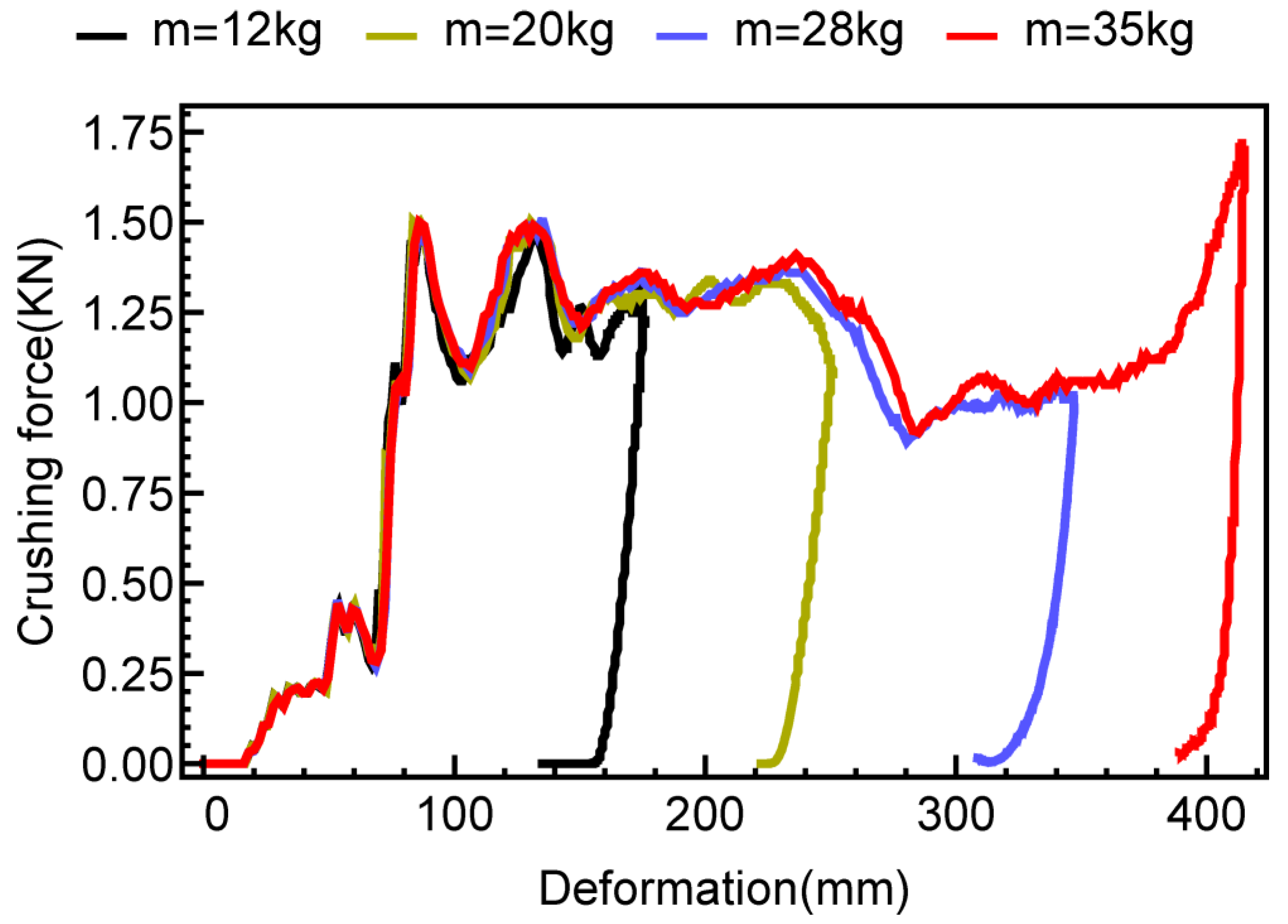
The effect of impact mass on the dynamic response of 3D AH is intuitively depicted in Figure 10, which plots the crushing force–deformation curves corresponding to variable impact mass (m = 12 kg, m = 20 kg, m = 28 kg and m = 35 kg) but constant initial impact velocity of v0 = 5 m/s. It is observed that the change in initial impact mass brings about nothing but the maximum crushing deformation of the structure. The implication is that the crushing process relies on the initial kinetic energy possessed by the impactor, which determines the ultimate structural deformation but not the dynamic characteristic of impact force if constant initial impact velocity is adopted.

4.2. Effects of Beam Radius and Node Yield Strength

Figure 11 shows the normalized plastic energy dissipation against strain of 3D AH at low-speed (V = 5 m/s) impact and high-speed (V = 50 m/s) impact. It is noticed in both impact scenarios that the energy absorption performance deteriorates due to the increase in beam radius. This can be explained by the deformation and failure mode of 3D AH under dynamic compressive loadings. When it is subjected to low-speed impact (such as v0 = 5 m/s), the 3D AH converts impact stroke into rotation and lateral collapse, which is rather a feature of rigid body motion with the increase in beam radius. The 3D AH with larger beam radius corresponds to higher plastic energy absorption capacity as the stronger dynamic effect, where the strain rate effect plays a dominant role in the plastic energy absorption.
Figure 12 compares the performance of plastic energy absorption of the chiral structures corresponding to different yield strengths of the nodes. It is observed that the yield strength of the node has a marginal effect on the energy absorption capability of 3D AH.

4.3. Effect of Impact Direction

Due to the unique spatial configuration of 3D AH, the deformation modes may be different when the impact varies in location. To investigate these effects, the two models of 3D AH were impacted in the X direction and in the Y direction, respectively. Similar to impact scenarios we considered in a previous parametric study, the chiral structures were loaded at velocities of 5 m/s and 50 m/s. Figure 13a,b present the normalized stress ( σ ¯ ) and normalized plastic strain energy ( U ¯ ) of chiral structures under low-speed impact and high-speed impact. It can be seen that in both cases, the chiral structure under impact in the X direction experiences larger impact stress and plastic energy dissipation than the chiral structure loaded in the Y direction in the initial crushing deformation, such as strain less than 30%. Afterwards, the impact behavior of the chiral structure in the Y direction leads to larger impact stress and better energy absorption performance. This can be explained by the different initial failure modes due to the impact in two directions. The dominant mechanism of plastic strain energy with the impact in the X direction is the axial and shear deformations of ligaments. Although the bending deformation of ligaments results in the main plastic energy dissipation in the initial stage of Y-direction impact, combined crushing of nodes, axial crushing and bending of ligament participate in the impact resistance afterwards.

5. Conclusions

This paper presents a numerical study on the impact behavior of a novel chiral auxetic possessing three-dimensional (3D) deformation capability. The new 3D chiral auxetic is designed by orthogonally assembling two 2D chiral auxetics but replacing the circular nodes-based conventional chiral auxetics (ACs) with hexagonal nodes-based chiral auxetics (AHs). The capability of the ABAQUS/Explicit model is validated against experimental results. The Poisson’s ratio of 2D AH is numerically obtained close to the theoretical value of −1, but parameter L determines the different value of Poisson’s ratio between 2D AC and 2D AH when considering the axial and shear deformations of ligaments, although this deflection is very limited. Thereafter, the study on compressive behavior of 3D AH is performed numerically using a model composed of 5 × 5 × 8 3D unit cells to eliminate the boundary effect. Based on the simulation results, the main conclusions can be drawn as follows:
  • The deformation modes of 3D AH highly depend on impact velocities. The σ ¯ and U ¯ increase as the impact velocity increases. When the impact velocity remains constant, larger initial impact mass results in an increase in maximum crushing deformation.
  • Increasing the beam radius leads to a decrease in specific energy absorption under both low-speed and high-speed compressive loadings. However, the energy absorption capability of 3D AH is not sensitive to the yield strength of nodes.
  • The impact behavior that occurred in the X direction results in higher impact stress and better energy absorption performance than the impact in the Y direction in the initial stage of compression (approximately 25% for low-speed impact and 19% for high-speed impact). Afterwards, the crushing deformation in the Y direction gives rise to a stronger capability of plastic energy dissipation than the impact in the X direction.
In practice, the 3D AH can be employed in the crashworthiness design and optimization of auxetic structures as energy absorbers used for structural protection and safety, since it ensures bidirectional shrinkage at the loaded zone and then results in higher resistance against impact and blast loads. The behavior and failure modes under various loadings, e.g., local impact loading and blast loading, are of larger practical relevance and will be the focus of future work. Additionally, the experimental study on impact behavior of 3D AH considering the effect of material properties, e.g., aluminum alloy and plastic used in 3D printing, will be carried out in our future work. The direct comparison of the impact mechanical properties of different 3D auxetic structures accounting for the same impact scenarios is of importance for optimum choice in practical application, which is an ongoing work and will be presented in a future publication.

Author Contributions

Methodology, D.G.; supervision, C.Z.; writing—original draft, D.G.; writing—review and editing, J.Z. All authors have read and agreed to the published version of the manuscript.

Funding

This research was funded by the National Natural Science Foundation of China (grant No.: 52201331), the National Key R&D Program of China (grant No.: 2021YFB2600800), the Natural Science Foundation of Liaoning Province (grant No.: 2023-MS-217), the Key Laboratory of Liaoning Province (2022JH13/10200060), the QNPY Foundation of Shenyang University of Technology (grant No.: 070/200005808) and the Talent Introduction Plan of Shenyang University of Technology (grant No.: 060/100030095). And the APC was funded by the National Key R&D Program of China (grant No.: 2021YFB2600800).

Institutional Review Board Statement

Not applicable.

Informed Consent Statement

Not applicable.

Data Availability Statement

The data presented in this study are available on request from the corresponding author.

Acknowledgments

The authors are very grateful to the editor and the anonymous reviewers for their precious time and insightful comments.

Conflicts of Interest

The authors declare no conflict of interest.

References

  1. Peroni, M.; Solomos, G.; Pizzinato, V. Impact behaviour testing of aluminium foam. Int. J. Impact Eng. 2013, 53, 74–83. [Google Scholar] [CrossRef]
  2. Ashab, A.S.M.; Ruan, D.; Lu, G.; Wong, Y.C. Quasi-static and dynamic experiments of aluminum honeycombs under combined compression-shear loading. Mater. Des. 2016, 97, 183–194. [Google Scholar] [CrossRef]
  3. Nian, W.; Subramaniam, K.V.L.; Andreopoulos, Y. Experimental investigation on blast response of cellular concrete. Int. J. Impact Eng. 2016, 96, 105–115. [Google Scholar] [CrossRef] [Green Version]
  4. Yahaya, M.A.; Ruan, D.; Lu, G.; Dargusch, M.S. Response of aluminium honeycomb sandwich panels subjected to foam projectile impact—An experimental study. Int. J. Impact Eng. 2015, 75, 100–109. [Google Scholar] [CrossRef] [Green Version]
  5. Imbalzano, G.; Linforth, S.; Ngo, T.D.; Lee, P.V.S.; Tran, P. Blast resistance of auxetic and honeycomb sandwich panels: Comparisons and parametric designs. Compos. Struct. 2018, 183, 242–261. [Google Scholar] [CrossRef]
  6. Zarei, H.; Kröger, M. Optimum honeycomb filled crash absorber design. Mater. Des. 2008, 29, 193–204. [Google Scholar] [CrossRef]
  7. D’Mello, R.J.; Waas, A.M. Inplane crush response and energy absorption of circular cell honeycomb filled with elastomer. Compos. Struct. 2013, 106, 491–501. [Google Scholar] [CrossRef]
  8. Liu, Q.; Fu, J.; Wang, J.; Ma, J.; Chen, H.; Li, Q.; Hui, D. Axial and lateral crushing responses of aluminum honeycombs filled with EPP foam. Compos. Part B-Eng. 2017, 130, 236–247. [Google Scholar] [CrossRef]
  9. Evans, K.E.; Alderson, A. Auxetic materials: Functional materials and structures from lateral thinking! Adv. Mater. 2000, 12, 617–628. [Google Scholar] [CrossRef]
  10. Evans, K.E. Auxetic polymers: A new range of materials. Endeavour 1991, 15, 170–174. [Google Scholar] [CrossRef]
  11. Love, A.E.H. A Treatise on the Mathematical Theory of Elasticity; Dover Publications: New York, NY, USA, 1944. [Google Scholar]
  12. Ren, X.; Das, R.; Tran, P.; Ngo, T.D.; Xie, Y.M. Auxetic metamaterials and structures: A review. Smart Mater. Struct. 2018, 27, 023001. [Google Scholar] [CrossRef]
  13. Pelliciari, M.; Pasca, D.P.; Aloisio, A.; Tarantino, A.M. Size effect in single layer graphene sheets and transition from molecular mechanics to continuum theory. Int. J. Mech. Sci. 2022, 214, 106895. [Google Scholar] [CrossRef]
  14. Pelliciari, M.; Tarantino, A.M. A nonlinear molecular mechanics model for graphene subjected to large in-plane deformations. Int. J. Eng. Sci. 2021, 167, 103527. [Google Scholar] [CrossRef]
  15. Qin, Z.Z.; Qin, G.Z.; Hu, M. Origin of anisotropic negative Poisson’s ratio in graphene. Nanoscale 2018, 10, 10365–10370. [Google Scholar] [CrossRef] [PubMed]
  16. Gao, D.; Wang, S.; Zhang, M.; Zhang, C. Experimental and numerical investigation on in-plane impact behaviour of chiral auxetic structure. Compos. Struct. 2021, 267, 113922. [Google Scholar] [CrossRef]
  17. Yu, R.; Luo, W.; Yuan, H.; Liu, J.; He, W.; Yu, Z. Experimental and numerical research on foam filled re-entrant cellular structure with negative Poisson’s ratio. Thin Wall Struct. 2020, 153, 106679. [Google Scholar] [CrossRef]
  18. Bettini, P.; Airoldi, A.; Sala, G.; Landro, L.D.; Ruzzene, M.; Spadoni, A. Composite chiral structures for morphing airfoils: Numerical analyses and development of a manufacturing process. Compos. Part B-Eng. 2010, 41, 133–147. [Google Scholar] [CrossRef] [Green Version]
  19. Li, T.T.; Chen, Y.Y.; Hu, X.Y.; Li, Y.B.; Wang, L.F. Exploiting negative Poisson’s ratio to design 3D-printed composites with enhanced mechanical properties. Mater. Des. 2018, 142, 247–258. [Google Scholar] [CrossRef]
  20. Wang, X.-T.; Wang, B.; Li, X.-W.; Ma, L. Mechanical properties of 3D re-entrant auxetic cellular structures. Int. J. Mech. Sci. 2017, 131–132, 396–407. [Google Scholar] [CrossRef]
  21. Wu, W.; Geng, L.; Niu, Y.; Qi, D.; Cui, X.; Fang, D. Compression twist deformation of novel tetrachiral architected cylindrical tube inspired by towel gourd tendrils. Extrem. Mech. Lett. 2018, 20, 104–111. [Google Scholar] [CrossRef]
  22. Wu, X.; Su, Y.; Shi, J. In-plane impact resistance enhancement with a graded cell-wall angle design for auxetic metamaterials. Compos. Struct. 2020, 247, 112451. [Google Scholar] [CrossRef]
  23. Liu, W.; Wang, N.; Luo, T.; Lin, Z. In-plane dynamic crushing of re-entrant auxetic cellular structure. Mater. Des. 2016, 100, 84–91. [Google Scholar] [CrossRef]
  24. Ingrole, A.; Hao, A.; Liang, R. Design and modeling of auxetic and hybrid honeycomb structures for in-plane property enhancement. Mater. Des. 2017, 117, 72–83. [Google Scholar] [CrossRef]
  25. Zhou, H.; Jia, K.; Wang, X.; Xiong, M.-X.; Wang, Y. Experimental and numerical investigation of low velocity impact response of foam concrete filled auxetic honeycombs. Thin Walled Struct. 2020, 154, 106898. [Google Scholar] [CrossRef]
  26. Gao, D.; Zhang, C. Theoretical and numerical investigation on in-plane impact performance of chiral honeycomb core structure. J. Struct. Integr. Main. 2018, 3, 95–105. [Google Scholar] [CrossRef]
  27. Airoldi, A.; Novak, N.; Sgobba, F.; Gilardelli, A.; Borovinšek, M. Foam-filled energy absorbers with auxetic behaviour for localized impacts. Mater. Sci. Eng. A 2020, 788, 139500. [Google Scholar] [CrossRef]
  28. Xu, Y.; Zhang, H.; Schlangen, E.; Luković, M.; Šavija, B. Cementitious cellular composites with auxetic behavior. Cem. Concr. Comp. 2020, 111, 103624. [Google Scholar] [CrossRef]
  29. Imbalzano, G.; Tran, P.; Ngo, T.D.; Lee, P.V.S. A numerical study of auxetic composite panels under blast loadings. Compos. Struct. 2016, 135, 339–352. [Google Scholar] [CrossRef]
  30. Logakannan, K.P.; Ramachandran, V.; Rengaswamy, J.; Ruan, D. Dynamic Performance of a 3D Re-entrant Structure. Mech. Mater. 2020, 148, 103503. [Google Scholar] [CrossRef]
  31. Mohsenizadeh, S.; Alipour, R.; Shokri Rad, M.; Farokhi Nejad, A.; Ahmad, Z. Crashworthiness assessment of auxetic foam-filled tube under quasi-static axial loading. Mater. Des. 2015, 88, 258–268. [Google Scholar] [CrossRef]
  32. Frenzel, T.; Kadic, M.; Wegener, M. Three-dimensional mechanical metamaterials with a twist. Science 2017, 358, 1072. [Google Scholar] [CrossRef] [PubMed] [Green Version]
  33. Fu, M.-H.; Zheng, B.-B.; Li, W.-H. A novel chiral three-dimensional material with negative Poisson’s ratio and the equivalent elastic parameters. Compos. Struct. 2017, 176, 442–448. [Google Scholar] [CrossRef]
  34. Wang, Q.S.; Yang, Z.Y.; Lu, Z.X.; Li, X. Mechanical responses of 3D cross-chiral auxetic materials under uniaxial compression. Mater. Des. 2020, 186, 108226. [Google Scholar] [CrossRef]
  35. Ha, C.S.; Plesha, M.E.; Lakes, R.S. Chiral three-dimensional lattices with tunable Poisson’s ratio. Smart Mater. Struct. 2016, 25, 054005. [Google Scholar] [CrossRef] [Green Version]
  36. Fu, M.H.; Liu, F.M.; Hu, L.L. A novel category of 3D chiral material with negative Poisson’s ratio. Compos. Sci. Technol. 2018, 160, 111–118. [Google Scholar] [CrossRef]
  37. Prall, D.; Lakes, R.S. Properties of a chiral honeycomb with a poisson’s ratio of—1. Int. J. Mech. Sci. 1997, 39, 305–314. [Google Scholar] [CrossRef]
  38. Spadoni, A.; Ruzzene, M. Elasto-static micropolar behavior of a chiral auxetic lattice. J. Mech. Phys. Solids 2012, 60, 156–171. [Google Scholar] [CrossRef] [Green Version]
  39. Hassan, M.R.; Scarpa, F.; Ruzzene, M.; Mohammed, N.A. Smart shape memory alloy chiral honeycomb. Mater. Sci. Eng. A 2008, 481–482, 654–657. [Google Scholar] [CrossRef]
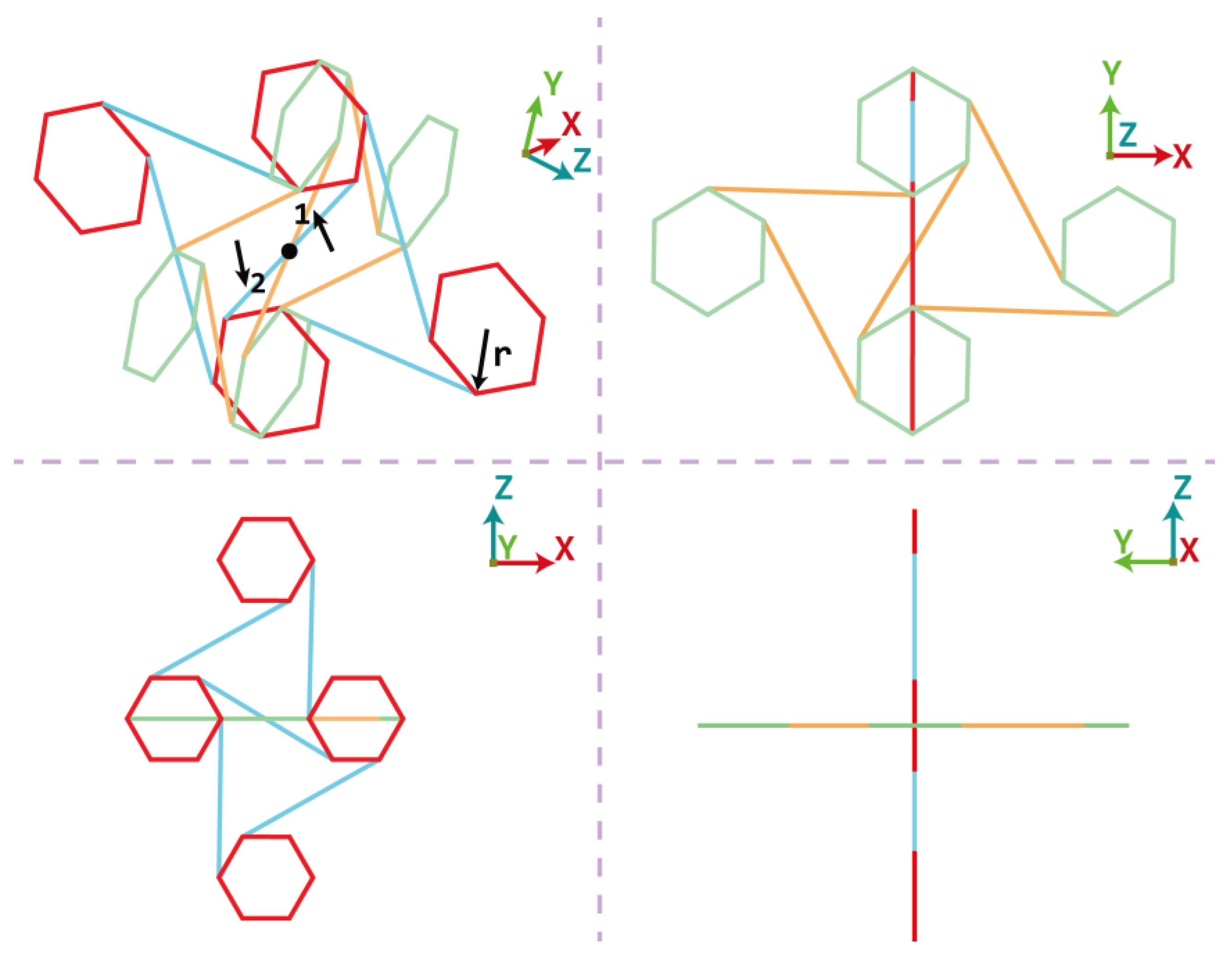
Figure 1. Schematic diagram of 3D chiral structure by orthogonally assembling two 2D unit cells of chiral auxetic structure while replacing the conventional circular nodes with hexagonal nodes. The hexagonal nodes with a radius r. The ligaments 1 and 2 from each unit cell joint together at the black point.
Applsci 13 08480 g001
Figure 2. Linear elastic deformation mechanism of 2D AH. The solid lines denote the undeformed state before load application. The dashed lines denote the deformed state when the uniaxial stress is applied.
Applsci 13 08480 g002
Figure 3. Measurement of Poisson’s ratio for 2D AH subject to displacement boundary conditions in (a) X direction, and (b) Y direction.
Applsci 13 08480 g003
Figure 4. Compression force−displacement curves and stress–strain curves of chiral structures measured from FE simulation and experimental test for (a) 2D and (b) 3D auxetic structures. Reprinted with permission from ref. [30], Copyright 2020 Elsevier.
Applsci 13 08480 g004
Figure 5. Poisson’s ratio νxy and νyx of 2D AH for loading along X (horizontal) and Y (vertical) directions, respectively.
Applsci 13 08480 g005
Figure 6. FE model of 3D AH in (a) front view, and (b) 3D view.
Applsci 13 08480 g006
Figure 7. Force−deformation curves and plastic energy dissipation−deformation curves of 3D AH corresponding to (a) different sizes and (b) different types of beam elements.
Applsci 13 08480 g007
Figure 8. (a) Deformed shapes of 3D AH against the crushing strain up to 50% at impact speed of 3 m/s (top left), 5m/s (middle left), 10m/s (bottom left), 20m/s (top right) and 50 m/s (middle right), respectively. (b) PR of 3D AH with strain corresponding to the impact speed between 3 m/s and 50 m/s.
Applsci 13 08480 g008
Figure 9. Compressive response of chiral structures under various impact velocities. (a) Normalized stress against strain; (b) normalized plastic energy dissipation against strain.
Applsci 13 08480 g009
Figure 10. Crushing force–deformation curves of 3D AH under different impact mass increasing from m = 12 kg to m = 35 kg.
Applsci 13 08480 g010
Figure 11. Normalized plastic energy dissipation against crushing strain of 3D AH with various beam radiuses, (a) impact at a velocity of 5 m/s; (b) impact at a velocity of 50 m/s.
Applsci 13 08480 g011
Figure 12. Normalized plastic energy dissipation against crushing strain of 3D AH with different values of nodes yield strength, (a) impact at a velocity of 5 m/s; (b) impact at a velocity of 50 m/s.
Applsci 13 08480 g012
Figure 13. Normalized plastic energy dissipation against crushing strain of 3D AH with different impact directions, (a) impact at a velocity of 5 m/s; (b) impact at a velocity of 50 m/s.
Applsci 13 08480 g013
Disclaimer/Publisher’s Note: The statements, opinions and data contained in all publications are solely those of the individual author(s) and contributor(s) and not of MDPI and/or the editor(s). MDPI and/or the editor(s) disclaim responsibility for any injury to people or property resulting from any ideas, methods, instructions or products referred to in the content.