Abstract
The parallelism of rule execution in membrane computing provides support for improving computational efficiency. Membrane computing models have been applied in many fields. In arithmetic operations, designing basic arithmetic operation spiking neural P systems using fewer neurons and rule types has been an important field of membrane computing application research in recent years. We discuss the application of locally homogeneous spiking neural P systems in arithmetic operations. The purpose is to design a spiking neural P system with fewer neurons and rule types to perform arithmetic operations. We designed the addition and subtraction of a locally homogeneous spiking neural P system without weight and delay. They include two input neurons to achieve any two binary number subtraction, one input neuron to achieve any two binary number addition and subtraction, and one input neuron to achieve any n binary number addition and subtraction. This is an attempt to apply the locally homogeneous spiking neural P system in arithmetic operations. Compared with the current excellent spiking neural P system performing arithmetic operations, our designed locally homogeneous spiking neural P system is more concise. The system we designed reduces the number of neurons required for n number addition operations by k − 6 and reduces the number of rule types by 5k − 14.
1. Introduction
Membrane computing [1,2] is one of the newest branches of biological computing. Membrane computing is inspired by cells and neural networks in the human body. The aim is to abstract the computational model from the way that living cells process compounds in a hierarchical structure, and obtain a new distributed and parallel computational model, which is called the P system. The spiking neural P system [3] (in short SN P system) is a biological computing system established with the idea of membrane computing. SN P system is one of the main types of P system. SN P system has the advantages of distribution, parallelism, and uncertainty. It provides a new algorithm model for biological system modeling and simulation. It also introduces new computational ideas and methods to computer science.
The spiking neural P system [1] consists of neurons, synapses, spikings, and rules. Intuitively, the SN P system is usually to represented as a graph. In the graph, nodes denote neurons, edges between nodes denote synapses, spikings and rules are seen as properties of nodes. Neurons are connected by synapses. Neurons send or receive spiking along the synapses. Rules in a neuron are designed according to its function. In each time slice, each neuron with an applicable rule must use and can use only one rule [4]. The spiking neural P system achieves computation with great parallelism of rule execution among neurons, resulting in powerful computational power. In recent years, researchers have proposed several variants of the SN P systems, which also have high computational performance and computational completeness. For example, a homogeneous SN P system with the same set of rules in each neuron. The Materials and Methods should be described with sufficient details to allow others to replicate and build on the published results. For example, ref. [5] proposed a homogeneous SN P system HSNPS with the same rule set in each neuron. Ref. [6] proposed a weighted fuzzy spiking neural P system WFSNPS, which can represent and process fuzzy and uncertain knowledge. Ref. [7] proposed an SN P systems RSSNPS that uses synapses as processors (synapses with rules). Ref. [8] proposed an astroglial spiking neural P system SNPAS composed of astrocytes and neurons. Ref. [9] proposed an SN P system ESNPS for combinatorial optimization problem solving with selection probability. Ref. [10] proposed an SN P system SNPSPS for synaptic remodeling accomplished by the invocation of rules in neurons. Ref. [11] proposed an adaptive optimization SN P system AOSNPS.
Homogeneous spiking neural P system (in short HSNP systems) is a new type of SN P system derived from the development of SN P systems. It has become one of the hotspots of membrane computing in recent years. Pan Linqiang et al. proposed the concept of HSNPS in the homogeneous spiking nervous P system in [5]. All neurons in the new SN P system are unified. All neurons in the P system have the same rule set. Since HSNPS was proposed, many variants of HSNP systems and different modes of operation have been studied. For example, ref. [12] proves that the HSNP system is universal as both generator and receiver in a sequential mode with a maximum number of spikes. Ref. [13] studied the small universal HSNP system with weights. Ref. [14] studied the HSNP system with reverse spiking without delay rule and synaptic weight. In [15], the HSNP system without delay rule is studied under the two conditions of weighted and unweighted synapses. Ref. [16] studied the number of neurons needed when the HSNP system works with maximum sequence and maximum spiking. Ref. [17] studied that the HSNP system with inhibitory synapses can reduce the types of neurons in the system. Ref. [18] applied the no-amnesia rule and HSNP system with astrocytes in the design of the logic gate, and constructed a more complex Boolean circuit. Ref. [19] verifies that the locally homogeneous spiking neural P system (LHSNP system) with the same set of rules for neurons in the same module can reduce the execution time of the system. HSNP systems with spikes and the same set of rules are studied in [20]. The HSNP system with structural plasticity that can delete and generate synapses has been studied in [21]. Ref. [22] studied the tag language generation method of the HSNP system with structural plasticity. Ref. [23] studied locally homogeneous SN P systems with local neurons having the same set of rules.
The research on arithmetic operations in the HSNP system is the foundation of the application research of the HSNP systems. At present, although there are more theoretical studies based on HSNP systems, there are fewer studies on the application of HSNP systems, especially arithmetic operations. The research results that can be used for reference mainly come from the research on arithmetic operations in SN P systems. For example, ref. [24] investigated SN P systems with n input neurons for addition, subtraction, and multiplication operations. Ref. [25] studied an SN P system with one input neuron and no weights in the synapse to perform the product of n natural numbers and any two natural numbers multiply. Ref. [26] studied an SN P system with multiple input neurons. It can perform integer arithmetic operations with signed operands. Refs. [27,28] studied an SN P system with multiple input neurons and takes the time interval between two spikings as the calculation result. They can perform arithmetic operations on any two natural numbers. Refs. [29,30] studied SN P systems with anti-spiking. It can perform addition and subtraction of symmetric three-valued integers. Ref. [31] studied an SN P system that uses CMOS circuits to implement the arithmetic module. Ref. [32] studied an SN P system with multiple input neurons and no delay. It can perform arithmetic operations. An SN P system with four neurons controlled by astrocytes was implemented through an arithmetic circuit [33]. An SN P system with rule sets and weights at synapses for calculating the maximum common divisor [34].
The fact that each neuron in the HSNP system has the same structure provides good support for the implementation of SN P systems. However, this also makes it difficult to represent the complexity and diversity of the computational process using the HSNP system. We studied the SN P system for performing arithmetic operations based on the LHSNP system. Our main contributions are as follows:
① This LSHNP system was designed to perform arithmetic operations and has no weight or delay. And we have added overflow monitoring neurons to monitor the overflow of calculation results in the system.
② We designed two LHSNP systems for addition. They are an LHSNP system with one input neuron that performs any two k-bit binary number addition operations. And an LHSNP system with one input neuron that performs any n k-bit binary number addition operations.
③ We designed three LHSNP systems for subtraction. LHSNP systems with multiple input neurons perform any 2 k-bit binary number subtraction operations. An LHSNP system with one input neuron can perform any 2 k-bit binary number subtraction operations. An LHSNP system with one input neuron can perform any n k-bit binary number subtraction operations.
The rest of the paper is structured as follows. Section 2 gives a brief description of the SN P system. In Section 3, we discussed the design of two LHSNP systems for addition, and in Section 4 we discussed the design of three LHSNP systems for subtraction. In Section 5, the conclusions of this paper and the issues to be further investigated are given.
2. Related Research
2.1. Spiking Neuronal P System
An SN P system of degree m (m ≥ 1) composed of five elements: the singleton alphabet, the neurons, the set of synapses, the input neurons, and the output neurons is a construct of the form [3]:
where:
П = (O, σ1, σ2, …, σm, syn, in, out)
- O = {a} is the singleton alphabet, and a is spiking;
- σ1, σ2, …, σm are neurons of the form σi = (ni, Ri), 1 ≤ i ≤ m, ni is the initial number of spiking in the neuron σi at the beginning of the calculation, ni ≥ 0. Ri is the finite set of rules in each neuron. Ri has two forms of rules (we collectively refer to them as spiking rules):
- ①
- E/ac → ap; d, where E is a regular expression over O, c ≥ 1, p ≥ 1, and c ≥ p, d indicates delayed time, d ≥ 0;
- ②
- E′/as → λ, s ≥ 1, for any rule E/ac → ap; d from any Ri, all meet the condition L(E)∩L(E′) = Φ;
- syn is the set of synapses. The element in syn is an ordered pair of elements shaped like (i, j). (i, j) indicates neurons σi to σj are connected by synapses, with i, j ∈ {1, 2, …, m}, i ≠ j;
- in, out ∈ {1, 2, …, m} indicate the input and output neurons.
In the SN P system, E/ac → ap; d is called a generalized firing rule. If L(E) = {ac}, then the rule can be written in the simplified form ac → ap; d. If p = 1, then the rule E/ac → a; d is called the standard firing rule. If p = 1 and d = 0, then the rule can be written in the simplified form E/ac → a. E′/as → λ is called the forgetting rule. If L(E) = {as}, then the rule can be written in the simplified form as → λ.
In this work, we use the no delayed rule (i.e., d = 0). Spiking rules are applied as follows: if at a time slice, neuron σi contains k spikings and ak ∈ L(E), k ≥ c, then the rule E/ac → ap ∈ Ri is enabled, σi is fired. σi will consume c spikings (only k-c spikes remain in σi) and send p spikings to all neurons connected to it. When σi contains s spikings (s ≥ 1), activating the forgetting rule as → λ ∈ Ri in σi. σi consum s spikings and do not send spikings to any neurons connected to it.
When all neurons in an SN P system have the same firing and forgetting rules, the system is called a homogeneous SN P system (HSNP system) [5]. The limitation of the HSNP system is that it is difficult to express efficient computation in the absence of redundant rules in neurons. For example, a binary adder with two input neurons can not be represented by an HSNP system without redundant rules. Therefore, this paper will study the local HSNP system (LHSNP system).
If the neurons in the system can be divided into several groups, and the neurons in each group use the same rules without redundancy, then we call it the LHSNP system. The goal of designing an LHSNP system that can perform effective calculations is to use the fewest number of neurons and the fewest number of neuronal groups in the system. For example, Formula (2) is an LHSNP system ПAdd1 with two input neurons that can perform binary addition.
where:
ПAdd1 = (O, σin1, σin2, σAdd, syn, Input1, Input2, out)
- (1)
- O = {a};
- (2)
- σin1 = (0, Rin);
- (3)
- σin2 = (0, Rin);
- (4)
- σAdd = (0, RAdd);
- (5)
- syn = {(in1, Add), (in2, Add)};
- (6)
- in1 = Input1, in2 = Input2;
- (7)
- out = Add;
- (8)
- Rin = {aa}, Radd = {aa, a2/, a3/a2a}.
2.2. Related Literature
The arithmetic operations we discussed in the article are performed in the eld of natural numbers (integers not less than 0) or their binary representation. The natural number N can be expressed as the k-bit binary number shown in Formula (3). The 2i (0 ≤ i ≤ k − 1) is called the bit weight, and ai is the value of the i + 1 bit (0 ≤ i ≤ k − 1).
N = a0*20 + a1*21 + a2*22 + a3*23 + … + ak−1*2k−1
In the LHSNP system, we assume that the system has a global clock to realize the synchronous execution of neuronal rules in parallel, with each rule executed in a time slice. The LHSNP system we designed to perform addition arithmetic operations is mainly compared to [25,34], and the LHSNP system that performs subtraction operations is mainly compared to [23].
Zhang Xingyi designed an SN P system with one input to perform n natural number addition in [25], which is weightless and has a delay. This SN P system with 3k + 5 neurons and 9 rule types requires (n + 1) k + 4 time slices to complete addition operations.
Wang Huifang designed an SN P system with one input to perform n natural number addition in [34], which has weights and delays. This SN P system with 2k + 4 neurons and 5k − 1 rule types requires a 5k − 1 time slice to complete addition operations.
Zeng Xiangxiang designed an SN P system with multiple inputs to perform two natural number subtraction in [23], which has no weight and delay. This SN P system with 12 neurons and 4 rule types requires a time slice that is free.
3. An Locally Homogeneous Spiking Neural P System for Addition
In this section, we will present two kinds of LHSNP systems with one input neuron. It can perform k-bit (k ≥ 4) binary number addition. They, respectively, perform addition operations on two numbers and on multiple numbers. In our designed system, if the representation of k-bit (k ≥ 4) binary numbers is less than k bits, the high bits of the binary numbers are automatically zeroed in.
The binary numbers involved in the calculation are input in order from low to high. The binary number 0 represents 0 spiking. The binary number 1 represents 1 spiking. The calculation results are output in the form of a spiking sequence (0 spiking represents binary number 0, 1 spiking represents binary number 1, and 4 spikings represent data overflow) to the environment.
3.1. An LHSNP System with 1 Input Neuron for 2 Numbers Addition
An LHSNP system ПAdd2 with one input neuron as Formula (4). The structure of ПAdd2 is shown in Figure 1. In Figure 1, the solid arrows represents the directed connection between two neurons. The dashed arrows indicates the omission of connections between multiple neurons. ПAdd2 design idea is as follows: ① Input part of the system is divided into two modules, which are the input module and the input cache module. The input module is composed of an input assist module and an input selection module. The input module controls the input of the summand and addend. It controls the summand through the auxiliary neuron σaux3 transmitted, and the addend through the additive neuron σaddend transmitted. When the summand input is completed and the addend input begins, with the assistance of the input auxiliary module, blocking addend pass through σaux3, and firing addend auxiliary neuron σaddend to transmit addend numbers. ② Auxiliary neuron σaux4 monitors the input of the highest bit of two binary numbers. When the highest bit of these two binary numbers arrived in the addition neuron σAdd. Auxiliary neurons σaux4 mark the highest bit corresponding spiking. ③ Summand and addend are calculated in the adder σAdd and the calculation result is sent to the environment. ④ Overflow monitoring neuron σOF monitors the calculation results whether overflow.
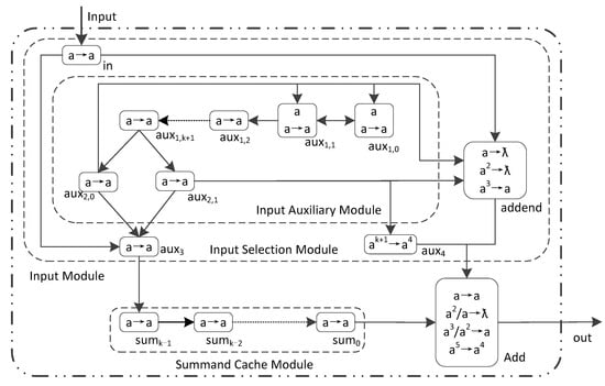
Figure 1.
The LHSNP system ПAdd2 with 1 input neuron for 2 k-bit binary numbers addition.
The rules of ПAdd2 are divided into four groups: (1) Homogeneous neurons: auxiliary neurons, summand catch neurons, and input neurons use rule set Raux = {a → a}. (2) Overflow monitoring neurons σaux4 uses rule set Raux4 = {ak + 1 → a4}. (3) Addend neuron σaddend uses rule set Raddend = {a → ƛ; a2 → ƛ; a3 → a}. (4) Adder neuron σAdd uses ruleset RAdd = {a → a; a2/a → ƛ; a3/a2 → a; a5 → a4}.
The formal definition of ПAdd2 is as Formula (4):
where:
ПAdd2 = (O, σin, σaddend, σaux1,0, σaux1,1, …, σaux1,k + 1, σaux2,0, σaux2,1, σaux3, σaux4, σsum0, σsum1, …, σsumk−1, σAdd, syn, Input, out)
- (1)
- O = {a};
- (2)
- σin = (0, Raux);
- (3)
- σaddend = (0, Raddend);
- (4)
- σaux1,i = (1, Raux), i = 0, 1;
- (5)
- σaux1,i = (0, Raux), i = 2, …, k + 1;
- (6)
- σaux2,i = (0, Raux), i = 0, 1;
- (7)
- σaux3 = (0, Raux);
- (8)
- σaux4 = (0, Raux4);
- (9)
- σsumi = (0, Rsum), i = 0, …, k − 1;
- (10)
- σAdd = (0, RAdd);
- (11)
- syn = {(in, aux3), (in, addend), (addend, Add), (aux1,1, aux1,0), (aux1,k + 1, aux2,0), (aux1,k + 1, aux2, 1), (aux2,0, aux3), (aux2,1, aux3), (aux2,0, addend), (aux2,1, addend), (aux2,0, aux1,0), (aux2,0, aux1,1), (aux2,1, aux4), (aux4, Add), (aux3, sumk−1), (sum0, Add)}∪{aux1,i, aux1,i + 1}|i ∈ {0, 1, …, k}∪{sumi + 1, sumi}|i ∈ {0, 1, …, k − 2};
- (12)
- in = Input;
- (13)
- out = Add.
Analysis of ПAdd2 and its rule set shows that ПAdd2 contains 8 rules and 2k + 9 neurons. Performing the addition operation of 2 k-bit binary numbers requires 2k + 3 time slices. Furthermore, we have the following conclusions:
Theorem 1.
ПAdd2 with 1 input neuron can perform any 2 k-bit binary number addition. In other words, ПAdd2 after receiving the spiking corresponding to each binary number bit in order from low to high, ПAdd2 can correctly perform addition and output the results to the environment.
Proof of Theorem 1.
Let t represent time slice. At the initial state t = 0, there is one spiking in σaux1,0 and σaux1,1. Starting from t = 1 time slice, two binary addends are in order received by σin from low to high. When the binary bit is 1, σin received 1 spiking, otherwise σin received 0 spiking. The corresponding binary bit of the summand are sequentially passed to σAdd along σaux3, σsumi (0 ≤ i ≤ k − 1) in summand cache module. The addend are sequentially passed to σAdd through σaddend. The calculation process of ПAdd2 is as follows:
- ①
- Input Auxiliary Module
The function of the input auxiliary module is to distinguish the summand from the addend. t = 1 to k + 1, the input auxiliary module does not generate spiking output. During this period, the spiking from σin (each bit of summand) is sent to the summand cache module through σaux3. σaddend consumed these spiking using rule a→λ. At t = k + 2 time slice, σaux2,0 and σaux2,1, respectively, send 1 spiking to σaux3. Maintain at least 2 spikings in σaux3. This prevents the addition input by σin from entering the neurons of the summand cache module. At the same time, σaddend received two spikings from σaux2,0 and σaux2,1, at least two spikings in σaddend. Thereby enabling the addend bit to enter σAdd to perform addition operations. The operation process of the input auxiliary module is as follows:
- (1)
- At t = 0 time slice, there is 1 spiking in σaux1,0 and σaux1,1.
- (2)
- t = 1 to k + 1, σaux1,0 and σaux1,1 send 1 spiking to each other and maintain 1 spiking. At the same time, σaux1,1 send 1 spiking to σaux1,2, which will follow the neurons σaux1,3, σaux1,4, …, σaux1, k + 1 sequential transmission. The input auxiliary module has no spiking output. At t = k + 1 time slice, there is 1 spiking in homogeneous neurons in the input auxiliary module.
- (3)
- t = k + 2 to 2k + 3, the input auxiliary module continues to generate spiking output. σaux2,0 send 1 spiking to σaux1,0 and σaux1,1 at each time slice to prevent σaux1,0 and σaux1,1 from continuously generating spiking. At t = k + 3 to 2k + 2 time slice, the spikings in σaux1,2, σaux1,3, …, σaux1,k + 1 are sequentially cleared. At t = 2k + 3 time slice, the spikings in σaux2,0 and σaux2,1 are cleared. And there are no rules that can be fired in all neurons in the input auxiliary module.
- ②
- Summand Input
The summand bits sent by σin transferred to σAdd along σaux3, σsumi (0 ≤ i ≤ k − 1). At t = 1 to k + 2 time slice, the summand cache module does not generate spiking output. At t = k + 3 to 2k + 2 time slice, σsum0 sends the corresponding spiking of each summand to σAdd at each time slice. The transmission process of the summand is as follows:
- (1)
- t = 1 to k, the spiking corresponding to each summand bit is received by σin in order from low to high. At t = k time slice, the input of the summand is completed. These spikings follow σaux3, σsumk−1, σsumk−2, …, σsum0 sequential transmission to σAdd.
- (2)
- t = k + 1 to k + 2, the summand cache module does not generate spiking output. At t = k + 2 time slice, the bits of the summand are stored in σsum0, σsum1, …, σsumk−1 in order from low to high. At the same time, σaux3 starts continuous reception spikings from σaux2,0, σaux2,1, and σin. Until 2k + 3 time slice, these spikings are piled up in σaux3.
- (3)
- t = k + 3 to 2k + 2, the summand cache module continuously generates spiking outputs. At each time slice, σsum0 sends the corresponding spiking of each summand to σAdd in sequence. At the same time, the spiking in σsumk−1, σsumk−2, …, σsum0 are sequentially cleared. Starting from 2k + 2 time slice, there are no rules that can use in the transmit addend neurons.
- ③
- Addend Input
The spiking corresponding to each addend sent by σin is sent to σAdd through σaddend. At t = 1 to k + 2 time slice, σAdd does not generate spiking output. At t = k + 3 to 2k + 3 time slice, σaddend sends the corresponding spiking of each addend bit to σAdd at each time slice. The transmission process of σaddend is as follows:
- (1)
- t = 1 to k + 2, σaddend does not generate spiking output. During this time, σaddend received spiking sent by σin is consume by forgetting rule a → ƛ.
- (2)
- t = k + 1 to 2k, the spiking corresponding to each binary addend is transmitted in order from low to high send to σin. At t = 2k time slice, the addend input is completed. These spikings through σaddend transferred to σAdd.
- (3)
- t = k + 2 to 2k + 1, σaddend receives spikings sent by σin. At each time slice, σAdd also receives 2 spikings sent by σaux2,0 and σaux2,1. With the assistance of σaux2,0 and σaux2,1,σaddend send spiking to σAdd transmission addend. During this time slice, if there are 2 spikings in σaddend, σaddend use the forgetting rule a2 → ƛ consuming 2 spikings and sending 0 spikings out. Indicates that the binary addend passed is 02. If there are 3 spikings in σaddend, firing rule a3 → a, consume 3 spikings and send 1 spiking out, indicating that the binary addend passed is 12. At t = k + 3 time slice, the spiking corresponding to the lowest bit of the addend is sent to σAdd. At t = 2k + 2 time slice, the spiking corresponding to the highest bit of the addend is sent to σAdd.
- ④
- Data Overflow Detection
The way to detect data overflow in σAdd is to use 4 spikings sent by σaux4 to detect whether the highest bit of the 2 addends have carry after calculation in σAdd. If there is a carry, then σAdd firing rule a5 → a4 and send 4 spikings to the environment to indicate data overflow. The input process for data overflow monitoring is as follows:
- (1)
- t = 1 to k + 1, σaux4 has no spiking input.
- (2)
- t = k + 2 to 2k + 2, σaux4 received 1 spiking sent by σaux2,1 at each time slice. These spikings are stacked in σaux4. At t = 2k + 2 time slice, σaux4 accumulated k + 1 spikings.
- (3)
- t = 2k + 3, σAdd received four spikings sent by σaux4 firing rule ak + 1 → a4. At the same time, σaux4 received 1 spiking sent by σaux2,1, which accumulates in σaux4 until the system stops. If there are 4 spikings in σAdd, it means that the calculation result does not overflow. If there are 5 spikings in σAdd, it indicates that the calculation result overflows. σAdd use the rule a5 → a4 to send 4 spikings to the environment.
- ⑤
- Addition Operation
Two addends are sent to σAdd in order of binary bits from low to high. At t = k + 3 to 2k + 2 time slice, the spiking corresponding to each of the two addends is sent to σAdd. At t = k + 4 to 2k + 3 time slice, σAdd send the calculation results to the environment. If 1 spiking is received in the environment, it represents binary number 1. If 0 spiking is received in the environment, it represents binary number 0. If 4 spikings are received in the environment at 2k + 4 time slices, it indicates data overflow. The design idea of σAdd is as follows: 1 spiking represents the binary number 1, and 0 spiking represents the binary number 0. If there is a carry generation after addition, retain 1 spiking in σAdd to indicate carry 1. The corresponding formulas for each rule in σAdd are as follows:
- (1)
- Rule a → a indicates performing addition operation: 12 + 02 = 12 or performing addition operation 02 + 02 + 12 = 02(there are carry reservations in σAdd). There are two types of sources for this spiking in σAdd. Case 1: This 1 spiking comes from σsum0 or σaddend. It indicates that the two binary addends input are 0 and 1. Case 2: This spiking comes from reserved in σAdd, and the two addends are 0. At this point, σAdd is fired using rule a → a, consumes 1 spiking and generates 1 spiking, and sends it to the environment.
- (2)
- Rule a2/a → ƛ indicates performing an addition operation: 12 + 12 = 102, or 12 + 02 + 12 = 102 (there is carry reservation in σAdd). There are two sources of these two spikings in σAdd. Case 1: these two spikings come from σsum0 and σaddend. This indicates that the two binary addends input are 1 and 1. Case 2: one spiking comes from σsum0 or σaddend, another spiking from σAdd (i.e., carry 1). At this point, σAdd is fired using rule a2/a → ƛ, consume 1 spiking, retain 1 spiking (i.e., carry 1), and send 0 spiking to the environment.
- (3)
- Rule a3/a2 → a indicates performing an addition operation: 12 + 12 + 12 = 112. These 3 spikings come from σsum0 and σaddend (the 2 binary addends input are 1 and 1) and 1 spiking reserved in σAdd (i.e., carry 1). At this point, σAdd is fired using rule a3/a2 → a, consumes 2 spikings, retains 1 spiking (i.e., carry 1), generates 1 spiking, and sends it to the environment.
- (4)
- Rule a5 → a4 indicates data overflow. Among these 5 spikings, 4 spikings come from σaux4, and 1 spiking comes from the two addends with the highest bits after calculation retained in σAdd (i.e., carry 1). At this point, rule a5 → a4 is fired in σAdd, which consumes 5 spikings and generates 4 spikings to be sent to the environment.
In summary, ПAdd2 can correctly perform the sum of 2 k-bit binary numbers. □
To illustrate the operation process in ПAdd2, an example is used to calculate the sum of 5 and 6. If the number of bits in the current system is 8, then 5 + 6 = 11 is represented as 000001012 + 000001102 = 000010112 in ПAdd2. During the calculation process, the number of spiking in all neurons at each time slice and the number of spiking sent to the environment are shown in Table 1. In Table 1, “t” represents the time slice, and in represents the number of spiking in σin. “in” represents the number of spiking in neuron σin. “aux3” and “aux4” represent the number of spiking in auxiliary neurons σauxi (i = 3, 4). “aux1,i (0 ≤ i ≤ 9) ”and “aux2,i (0 ≤ i ≤ 1)” represent the number of spiking in auxiliary neurons σauxj,i (1 ≤ j ≤ 2, 0 ≤ i ≤ 9). “sumi” represents the number of spiking in the auxiliary neuron σsumi (0 ≤ i ≤ 7). “addend” represents the number of spiking in additive neuron σaddend. “Add” represents the number of spiking in the addition operation neuron σAdd. “out” represents the number of spiking sent to the environment. “sum6 … sum1” indicates the omission of presenting spiking in σsum1 to σsum6. “aux1,3 … aux1,8” indicates the omission of spiking in σsum1,3 to σsum1,8. The two binary addends input and the calculation results are represented in bold font.

Table 1.
The number of spiking of all neurons in the ПAdd2 and the number of spiking sent to the environment during the calculating of 000001012 + 000001102 = 000010112.
The process of calculating the sum of 000001012 and 000001102 in ПAdd2 is as follows:
- ①
- Input Auxiliary Module
The spiking in the auxiliary module send by σaux1,1 is transmitted along σaux1,2, σaux1,3, …, σaux1,9. All of them are homogeneous neurons, and the transmission situation of each neuron is similar. Therefore, the description of spiking situations in aux1,3…aux1,8 is omitted in Table 1.
- (1)
- t = 1 to 9, the input auxiliary module does not generate spiking output. At each time slice, σaux1,0 and σaux1,1 continuously send spiking to each other, while σaux1,1 continuously sends spiking to σaux1,2. This spiking along σaux1,3, σaux1,4, …, σaux1,9, σaux2,i (i = 0, 1) sequential transmission. At t = 9 time slice, all neurons in the input auxiliary module have 1 spiking.
- (2)
- t = 10 to 19, σaux2,0 continuously sending spiking to σaux1,0 and σaux1,1. At t = 10 time slice, σaux1,0 and σaux1,1 also received 1 spiking sent by each other. These spikings are stacked in σaux1,0 and σaux1,1. At t = 11 time slice, σaux1,0 and σaux1,1 stop generating spiking output. At t = 10 to 19 time slices, σaux2,0 and σaux2,1 continuously generate spiking output. At t = 11 to 19 time slices, the spikings in σaux1,2, σaux1,3, …, σaux1,9, σaux2, i (i = 0, 1) are sequentially cleared. At t = 19 time slice, there are 11 spikings stacked in σaux1,0 and σaux1,1. And there is no spiking in σaux1,3, σaux1,4, …, σaux1,9, σaux2, i (i = 0, 1).
- ②
- Summand Input
The spiking corresponding to the addend bit is received by σin in order from low to high. These spikings along the σaux3, σsum7, …, σsum0 transferred to σAdd. Due to the fact that the summand input during time slice t = 5 to 8 are all 0, the spiking situation in the system during that time period is omitted from Table 1.
- (1)
- t = 1 to 8, the spiking 1, 0, 1, 0, 0, 0, 0, 0, 0, 0, 0, 0 corresponding to the summand from low to high are sequentially received by σin. These spikings along the σaux3, σsum7, …, σsum0 transferred to σAdd. At t = 1 time slice, spiking 1 corresponding to the lowest bit of the summand is received by σin. At t = 8 time slice, the spiking 0 corresponding to the highest bit of the addend is received by σin.
- (2)
- t = 2 to 9, σin sends spiking to both σaux3 and σaddend. σaddend uses forgetting rule a → ƛ to consume these spiking.
- (3)
- t = 10, the summand is stored in ascending order from low to high in the σsum0, σsum1, …, σsum7. There are 1, 0, 1, 0, 0, 0, 0, 0, 0, 0 spikings in σsum0, σsum1, …, σsum7.
- (4)
- t = 11 to 18, the spiking corresponding to each summand is sequentially in order from low to high received by σAdd.
- ③
- Addend Input
The spiking corresponding to the addend is sorted in order from low to high received by σin. These spikings pass through σaddend transferred to σAdd. Due to the fact that the spiking output to the environment during the time slice t = 16 to 18 is all 0, the spiking situation in the system during this time period is omitted from Table 1.
- (1)
- t = 1 to 10, there is no spiking output in σaddend.
- (2)
- t = 9 to 16, the corresponding spiking 0, 1, 1, 0, 0, 0, 0, 0, 0, 0, 0 of the addend from low to high are sequentially represented received by σin. These spikings through σaddend transferred to σAdd. At t = 9 time slice, the spiking 0 corresponding to the lowest bit of the addend is received by σin. At t = 16 time slice, the spiking 0 corresponding to the highest bit of the addend is received by σin.
- (3)
- t = 10 to 17, there are 2, 3, 3, 2, 2, 2, 2, 2, 2 spikings in σaddend at each time slice. These spikings come from σaux2,0, σaux2,1, and σin. During the time slice t = 10 to 17, σaux3 receives spikings sent by σaux2,0, σaux2,1 and σin at each time slice. At t = 17 time slice, there are 18 spikings stacked in σaux3.
- (4)
- t = 11 to 18, the spiking in σsum7, σsum6, …, σsum0 are sequentially cleared.
- ④
- Overflow Monitoring
- (1)
- t = 0 to 9, there is no spiking input in σaux4.
- (2)
- t = 10 to 18, σaux4 receives 1 spiking sent by σaux2,1 at each time slice. And stack these spiking in σaux4. At t = 18 time slice, 9 spikings stacked in σaux4.
- (3)
- At t = 19 time slice, σaux4 sends 4 spikings after using rule a9 → a4 to σAdd. At this point, the highest bit of the two addends have been calculated and no carry has been generated. There are 4 spikings in σAdd, no rules can be use, and there is no data overflow. At the same time, σaux4 received 1 spiking sent by σaux2,1, which is stacked in σaux4.
- ⑤
- Addition Operation
- (1)
- t = 1 to 10, there is no spiking input in σAdd.
- (2)
- t = 11 to 18, the spiking corresponding to each of the two binary addends is sent in sequence from low to high to σAdd. At t = 11 time slice, σAdd received the spiking corresponding to the lowest order of two addends. At this time, there is 1 spiking in σAdd. At t = 18 time slice, σAdd received spiking corresponding to the highest bit of 2 addends, there are 0 spiking in σAdd.
- (3)
- t = 12 to 19, it is the effective output time of ПAdd2. During this time slice, the calculation results are sent to the environment in order from low to high. In each time slice, the environment received 1, 1, 0, 1, 0, 0, 0, 0, 0, 0, 0 spikings in sequence.
- (4)
- t = 19, σAdd received 4 spikings sent by σaux4. At this time, there are no rules that can be used in ПAdd2, and the system operation stops. The system ПAdd2 calculates that the sum of 000001012 and 000001102 is 000010112, and the calculation result is correct.
From Table 1, it can be seen that the effective output time of the system is t = 12. And the sum of two natural numbers 5 and 6 is 000010112, which is 11. The addition LHSNP system constructed of ПAdd2 can perform the addition operation of 2 k-bit binary numbers.
3.2. An LHSNP System with 1 Input Neuron for n-addition
ПAdd2 can only add two binary numbers, which has limitations in practical applications. In practical applications, it is more necessary to complete n-addition. Therefore, this section has made improvements to ПAdd2, and the structure of the improved LHSNP system ПAdd3 with one input neuron is shown in Figure 2. In Figure 2, the solid arrows represents the directed connection between two neurons. The dashed arrows indicates the omission of connections between multiple neurons. Due to the similarity between ПAdd3 and ПAdd2, the formal definition of ПAdd3 has been omitted.
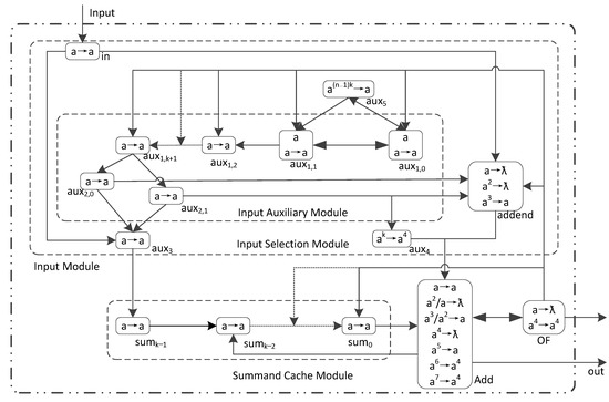
Figure 2.
The LHSNP system ПAdd3 with 1 input neuron for n k-bit binary numbers addition.
The design thought of ПAdd3 is as follows: ① The system input part is divided into two modules, namely the input module and the input cache module. The input module is composed of an input selection module and an input assistance module. The input module controls the input of the summand and addend: the summand (the first addend) is transmitted through the auxiliary neuron σaux3, while the addend is transmitted through the addend neuron σaddend. After the input of the summand is completed, with the assistance of the input auxiliary module, the addend is stopped through σaux3 transmitted. And σaddend is firing to translate addend. ② High-level monitoring neuron σaux4 monitors the highest bit of two binary addends. When the highest bit of two binary addends are reached the addition operation neuron σAdd. σaux4 sends 4 spiking to σAdd to mark the highest bit. ③ Two addends complete the addition calculation in σAdd and send the operation results to the environment and the summand cache module. The spiking waiting stored in the summand cache module completes the addition calculation with the next addend in σAdd, thereby achieving accumulate plus. ④ Overflow monitoring neuron σOF monitors whether the calculation overflow. If the calculation result overflow, σOF sends spiking to the environment and some neurons in ПAdd3, the aim is terminal the operation of ПAdd3. ⑤ Spiking control neuron σaux5 controls σaux1,0 and σaux1,1 to stop generating spiking output.
The rules of ПAdd3 are divided into six groups: (1) Homogeneous neurons: auxiliary neurons, summand cache neurons, σaux3, and input neurons use rule set R = {a → a}. (2) High-level monitoring neuron σaux4 uses rule set Raux4 = {ak → a4}. (3) Spiking control neuron σaux5 uses rule set R aux5 = {a(n−1)k → a}. (4) Addend neuron σaddend uses rule set Raddend = {a → ƛ; a2 → ƛ; a3 → a}. (5) Addition operator neuron σAdd uses rule set RAdd = {a → a; a2/a → ƛ; a3/a2 → a; a4 → ƛ; a5 → a; a6 → a4; a7 → a4}. (6) Overflow monitoring neuron σOF uses rule set ROF = {a → ƛ; a4 → a4}.
Analyzing Figure 2, it can be seen that ПAdd3 contains 13 rules, 2k + 11 neurons, and completing n-addition operations requires nk + 3 time slices. Furthermore, we have the following conclusion:
Theorem 2.
ПAdd3 can perform any n k-bit binary number addition operations with 1 input neuron. That is, ПAdd3 receives spiking corresponding to binary numbers in order from low to high. And it can correctly complete the addition operation and output result to the environment in order from low to high.
Proof of Theorem 2.
Let t stand the time slice. At the initial state t = 0, there is 1 spiking in σaux1,0 and σaux1,1. Starting from t = 1 time slice, the spiking corresponding to n k-bit binary addends are received by σin in order from low to high. The spiking corresponding to the first binary addend is sequentially transmitted to σAdd through σaux3 and the auxiliary neuron σsumi (0 ≤ i ≤ k − 1) in the summand cache module. The spiking corresponding to the 2nd to nth addends is sequentially transmitted to σAdd through σaddend. The calculation process of ПAdd3 is as follows:
- ①
- Input Assistance Module
The input assistance module of ПAdd3 is similar to ПAdd2, and compared to ПAdd2, ПAdd3 has made the following improvements:
- (1)
- Add an auxiliary neuron σaux5. σaux5 and σaux1,0 connected to each other. And σaux5 is also connected to σaux1,1. σaux5 controls σaux1,0 and σaux1,1 to stop generating spiking. σaux1,0 send 1 spiking to σaux1,1 while also sending 1 spiking to σaux5. These spikings accumulate in σaux5 until the number of spiking reaches (n − 1)k. When there are (n − 1)k spikings, σaux5 is fired and sends spiking to σaux1,0 and σaux1,1 to stop generating spiking output.
- (2)
- Add a connection between σAdd and σsumk−2. σAdd send the calculation results to both the environment and σsumk−2 for accumulate plus.
- (3)
- Add overflow monitoring neuron σOF. If data overflow, σOF sends 4 spikings to some neurons in the system truncation spiking transmission. The aim is to stop the system.
- (4)
- Modify the conditions for firing σaux4. If the number of stacked spiking in σaux4 reaches k, then firing σaux4 sends 4 spikings to σAdd to mark the highest bit of the 2 addends in σAdd.
- ②
- The First Addend Input
The first addend is passed to σAdd through the auxiliary neurons σin, σaux3, and the addend cache module in order of binary bits from low to high. The process of inputting the first addend is as follows:
- (1)
- t = 1 to k, the spiking corresponding to the first binary addend is received by σin in order from low to high. At each time slice, these spikings are transmitted sequentially along σaux3, σsumk−1, σsumk−2, …, σsum0. At the same time, σaddend also receives spikings from σin at each time slice. These spikings are consumed by rule a → ƛ in σaddend. In order to stop the first addend transmit through σaddend.
- (2)
- t = k + 1 to k + 2, the addend cache module does not generate spiking output. At t = k + 2 time slice, the spiking corresponding to each bit of the first binary addend is sequentially stored in σsum0, σsum1, …, σsumk−1 from low to high. At the same time, σaux3 continues to receive spiking sent by σin, σaux2,0, σaux2,1 until (n − 1) k + 3 time slice. And these spikings accumulate in σaux3.
- (3)
- t = k + 3 to 2k + 2, the spiking corresponding to the first binary addend is sequentially received by σAdd. At t = 2k + 2 time slice, the spiking corresponding to the highest bit of the first addend is received by σAdd.
- ③
- The 2nd to nth Addend Input
The spiking corresponding to the second to nth binary addends are received by σin in order from low to high. And these spikings are transmitted to σAdd through σaddend. The process of inputting the 2nd to nth addends is as follows:
- (1)
- t = 1 to k + 1, σaddend does not generate spiking output.
- (2)
- t = (i − 1) k + 1 to ik (2 ≤ i ≤ n), the spiking corresponding to the i-th binary addend is received by σin in order from low to high. At each time slice, these spikings are transmitted to σAdd through σaddend.
- (3)
- t = (i − 1) k + 2 to ik + 1 (2 ≤ i ≤ n), the spiking corresponding to the i-th binary addend is sequentially received by σaddend. At the same time, σaddend will also receive 1 spiking sent by σaux2,0 and σaux2,1 at each time slice. σaux2,0 and σaux2,1, σaddend is fired and send spiking to σAdd. If there are 2 spikings in σaddend, σaddend firing rule a2 → ƛ sends 0 spiking to σAdd. If there are 3 spikings in σaddend, σaddend firing rule a3 → a to send 1 spiking to σAdd.
- (4)
- t = (i − 1) k + 3 to ik + 2 (2 ≤ i ≤ n), the spiking corresponding to the nth binary addend is sequentially received by σAdd. At t = ik + 2 (2 ≤ i ≤ n) time slice, the highest bit of the 2nd to nth addend is received by σAdd.
- ④
- N-addition
For each time slice starting from k + 3, σAdd receive the spiking corresponding to two binary addends in sequence from low to high. And outputs the operation results to σsumk−2, the environment, σOF, and summand cache module. The spiking output to the environment represents the current calculation result. If there is no overflow in the calculation result, the effective output time of ПAdd3 is (n − 1) k + 4 to nk + 3. σAdd sends the operation results to σsumk−2 and waits for the next addend to complete the accumulated subtraction in σAdd. That is, the operation results of the two addends in this operation with the next addend accumulate subtraction in σAdd. σOF monitors whether the highest bit calculation result in σAdd overflows. The process of implementing the accumulation of n k-bit binary numbers is as follows:
- (1)
- t = 1 to k + 2, there is no spiking input in σAdd.
- (2)
- t = k + 3 to 2k + 2, the spiking corresponding to the first and the second addends are sequentially received by σAdd. At t = k + 4 to 2k + 3 time slice, σAdd simultaneously sends the calculation results to the environment, σsumk−2 and σOF at each time slice. At t = k + 4 time slice, the lowest order of the results of two addend operations is output to the environment, σOF, and σsumk−2. At t = (i − 1) k + 4 to ik + 3 (2 ≤ i ≤ n) time slice, σAdd sends the calculation results to the environment, σsumk−2 and σOF at each time slice.
- (3)
- At t = k + 4 until the system stops, the summand cache module receives spiking sent by σAdd at each time slice. These spikings are transmitted along σsumk−3, σsumk−4, …, σsum0. At t = 2k + 2 time slice, the results of the first and the second addends are stored in σsum0, σsum1, …, σsumk−1 in order from low to high. At t = ik + 2 (2 ≤ i ≤ n) time slice, the operation results of n addends are stored in σsum0, σsum1, …, σsumk−1 in order from low to high.
- (4)
- From t = 2k + 3 to 3k + 2, complete accumulate plus in σAdd. At t = (i − 1) k + 3 to ik + 2 (2 ≤ i ≤ n), complete the accumulation with the i-th addend.
- (5)
- In the absence of overflow in the calculation results, (n − 1) k + 4 to nk + 3 time slice is the effective output time of ПAdd3. At nk + 3 time slice, the highest bit of n addend calculation results is output to the environment.
- ⑤
- Adder
The process of implementing the addition operation in ПAdd3 by the addition operator σAdd is as follows:
There are a total of seven rules in σAdd, of which four are: a4 → ƛ; a5 → a; a6 → a4; a7 → a4 is used to detect whether the highest bit of two binary addends participates in the calculation of σAdd and whether the calculation result overflows. The implementation of the seven rules in σAdd is as follows:
- (1)
- Rule a → a represents executing equation 12 + 02 = 12. It consume one spiking in σAdd and send one spiking outward, which is the calculation result.
- (2)
- a2/a → ƛ indicates the execution of equation 12 + 12 = 102. One spiking retainedin σAdd indicating carry 1, and zero spikings sent outward indicating the operation result 0.
- (3)
- a3/a2 → a indicates the execution of equation 12 + 12 + 12 = 112. One spiking retain in σAdd indicates carry 1, and one spiking sent outward indicates the operation result 1.
- (4)
- a4 → ƛ; a5 → a; a6 → a4; a7 → a4 is used to perform the highest order operation. a4 → ƛ indicates that the highest order calculation performed is 02 + 02 = 02. a5 → a indicates that the highest order calculation performed is 12 + 02 = 12. a6 → a4 indicates that the highest bit calculation performed is 12 + 12 = 102, which indicates that data overflow and sends out 4 spikings. a7 → a4 indicates that the highest bit calculation performed is 12 + 12 + 12 = 112, which indicates that data overflow. σAdd sends 4 spikings outward.
- ⑥
- Data Overflow Monitoring
σaux4 send spiking to σAdd to mark the highest bit of each addition operation in σAdd. Pass 4 rules in σAdd: a4 → ƛ; a5 → a; a6 → a4; a7 → a4 detects whether the highest bit calculation result overflows. If the calculation result overflows, σAdd sends 4 spikings outward. If the environment received 4 spikings, it indicates that data overflow. After receiving 4 spikings in σOF, 4 spikings are sent to each neuron σaux1,i (0 ≤ i ≤ k + 1), σaux2,i (0 ≤ i ≤ k − 3), σAdd and σaddend to cut off the transmission of spiking in ПAdd3, causing the system to stop running. The process of data overflow monitoring is as follows:
- (1)
- t = 1 to k + 1, there is no spiking input in σaux4.
- (2)
- t = (i − 1) k + 2 to ik + 1 (2 ≤ i ≤ n), σaux4 receives 1 spiking sent by σaux2,1 at each time slice, and these spikings are stacked in σaux4. At t = ik + 2 (1 ≤ i ≤ n) time slice, σaux4 is fired using rule ak → a send 4 spikings to σAdd.
In summary, the above ПAdd3 can perform any n k-bit binary number addition operations with one input neuron. □
To illustrate the operation process of ПAdd3 shown in Figure 2, take the sum of three natural numbers 134, 134, and 1 as an example for illustration. The binary form of these three natural numbers is 100001102, 100001102, and 000000012. In ПAdd3, n is 3 and the system is 8-bit, which means k is 8. Table 2 shows the number of spiking in all neurons at each time slice in ПAdd3. In Table 2, “t” represents the time slice. “in” represents the number of spiking in neuron σin. “aux1,i (0 ≤ i ≤ k + 1)”, ”aux2,i (0 ≤ i ≤ 1)” and “aux3” represents the number of spiking in the auxiliary neuron. “aux4” represents the number of spiking in the high-level monitoring neuron σaux4. “aux5” represents the number of spiking in the spiking control neuron σaux5. “sumi (0 ≤ i ≤ k − 1)” represents the number of spiking in the summand auxiliary neuron σsumi (0 ≤ i ≤ k − 1). “addend” represents the number of spiking in the addend neuron σaddend. “Add” represents the number of spiking in the addition operation neuron σAdd. “out” represents the number of spiking sent to the environment. “OF” represents the number of spiking in the overflow monitoring neuron σOF. The input n addends and the output operation results are represented in bold font.
Table 2.
The number of spiking of all neurons in ПAdd3 and the number of spiking sent to the environment during the calculation of 100001102 + 100001102 + 000000012.
The calculation process for the three binary numbers 00001102, 100001102, and 000000012 in ПAdd3 is as follows:
- ①
- Input Auxiliary Module
- (1)
- t = 0, there is 1 spiking in σaux1,0 and σaux1,1.
- (2)
- t = 1 to 9, σaux1,0 and σaux1,1 send spiking to each other and maintain one spiking in. At the same time, σaux1,1 send 1 spiking to σaux1,2 at each time slice. These spikings are transmitted sequentially along σaux1,2, σaux1,3, …, σaux1,9. σaux1,1 will send 1 spiking to σaux5 at each time slice, these spikings are stacked in the σaux5. During this time slice, the input auxiliary module does not generate spiking output.
- (3)
- t = 10 to 17, all neurons in the input auxiliary module maintain 1 spiking. At the same time, σaux2,1 send 1 spiking to σaux4 at each time slice. And these spikings are stacked in σaux4. σaux1,1 send 1 spiking to σaux5 at each time slice. And these spikings are stacked in σaux5. At t = 17 time slice, there are 8 spikings stacked in σaux4 and 16 spikings stacked in σaux5.
- (4)
- t = 18 to 21, the neurons in the input auxiliary module stop sending spikings in the order of (σaux1,0, σaux1,1), σaux1,2, σaux1,3, …, σaux1,9, (σaux2,0, σaux2,1). At t = 18 time slice, σaux1,0 and σaux1,1 receives 1 spiking sent by σaux5 firing rule a16 → a. σAdd received 4 spikings sent by σaux4 firing rule a8 → a4. At t = 20 time slice, σaux1,0, σaux1,1, σaux1,2, …, σaux1,9 receives 4 spikings sent by σOF and cut off the transmission of the spiking in neurons. At t = 21 time slice, the spiking in σaux2,0, σaux2,1 are consumed and there are no rules to fire in the input auxiliary module.
- ②
- The First Addend Input
- (1)
- t = 1 to 8, σin received spiking corresponding to bit of the first binary addend.
- (2)
- t = 2 to 18, the first addend is transmitted along σaux3, σsum7, σsum6, …, σsum0, σAdd at each time slice. At t = 2 to 9 time slice, σaddend received spiking sent by σin. This spikings are consumed by the forgetting rule a → ƛ in σaddend. At t = 10 time slice, the spiking corresponding to the first addend is stored in σsum7, σsum6, …, σsum0 in order from low to high. At t = 11 time slice, the spiking corresponding to the lowest bit of the first addend is received by σAdd. At t = 18 time slice, the spiking corresponding to the highest bit of the first addend is received by σAdd.
- ③
- The Second Addend Input
- (1)
- t = 1 to 9, σaddend does not generate spiking output.
- (2)
- t = 9 to 16, σin receives bits of the second binary addend.
- (3)
- t = 10 to 18, the second addend is transmitted along σaddend and σAdd at each time slice. At t = 10 to 17 time slice, σaux3 received spiking sent by σin, and 2 spikings sent by σaux1,0 and σaux1,1. These spikings are stacked in σaddend. At t = 11 time slice, the spiking corresponding to the lowest bit of the second addend is received by σAdd. At t = 18 time slice, the spiking corresponding to the highest bit of the second addend is received by σAdd.
- ④
- The Third Addend Input
- (1)
- t = 17 to 21, σin receives the last 5 bits of the third binary addend.
- (2)
- t = 18 to 21, the third addend is transmitted along σaddend and σAdd at each time slice. At t = 18 to 21 time slice, σaux3 received spiking sent by σin, and 1 spiking sent by σaux1,0 and σaux1,1. These spikings are stacked in σaddend. At t = 19 time slice, the spiking corresponding to the lowest bit of the third addend is received by σAdd. At t = 21 time slice, the spiking corresponding to the a6 bit of the third addend is received by σAdd.
- ⑤
- Addition
- (1)
- t = 1 to 10 does not have an addend reaching σAdd. So, there is no spiking in σAdd.
- (2)
- t = 11 to 18, the first and the second addends are received by σAdd in order from low to high. At t = 18 time slice, the highest bits of the first and second addends are received by σAdd, and the 4 spikings sent by σaux4 are received by σAdd too.
- (3)
- t = 12 to 19, the operation results of the first and the second addends are sent to the environment, σOF and σsum6. At t = 19 time slice, the environment, σOF and σsum6 receive 4 spikings sent by σAdd using rule a6 → a4. It indicates data overflow.
- (4)
- t = 20, σOF is fired and send 4 spikings to σAdd, σaux1,2, σaux1,3, … σaux1,9. At the same time, the environment, σOF and σsum6 received 1 spiking sent by σAdd.
- (5)
- At t = 21 time slice, there is no rule can be firing in σAdd and σOF. ПAdd3 stops running.
From Table 2, it can be seen that data overflow occurred during the calculation process of ПAdd3. At t = 19 time slice, the spiking sent to the environment is 4. Therefore, the calculation result is abnormal and exceeded the range of ПAdd3 calculation, resulting is overflow. At t = 21 time slice, the system stops running.
3.3. Comparison
This section implements two different types of addition LHSNP systems ПAdd2 and ПAdd3. The two additive LHSNP systems designed in this article and the additive P systems designed in [25,34] require the number of neurons, the time required to complete the operation, and the number of rules in the system, as shown in Table 3.
Table 3.
Two types of LHSNP systems for addition.
There is no SN P system with one input for two k-bit binary number addition designed in [25,34]. Therefore, ПAdd2 is analyzed in comparison with ПAdd3. ПAdd3 adds 2 neurons compared to ПAdd2. ПAdd3 completes calculations with (n − 2)k more time slice than ПAdd2. ПAdd3 has 5 more rules than ПAdd2. Although ПAdd2 is superior to ПAdd3. But ПAdd3 can implement the addition operation of n k-bit binary numbers. ПAdd3 has a wider range of applications.
ПAdd3 has 13 rules, requiring 2k + 11 neurons and nk + 3 time slices to complete the calculation. Compared to the SN P system for addition proposed by Zhang Xingyi in [25]. Our designed ПAdd3 has increased the number of rules by 4. But the number of neurons has been reduced by k − 6 compared to [25], and the time required to complete the calculation has been reduced by k + 1 time slice. It greatly optimizes the additive SN P system. In the SN P system with weights and delays for addition proposed by Wang Huifang et al. in [34], we removed weights and delays by increasing the number of neurons. Compared with [34], our designed ПAdd3 adds 7 neurons, but the time required to complete the calculation has been reduced by k − 2 time slice, and the number of rules has been reduced by 5k − 14. This not only simplifies the system but also greatly improves its performance.
4. An Locally Homogeneous Spiking Neural P System for Subtraction
In this section, we will present three kinds of LHSNP systems with one and two input neurons for k-bit (k ≥ 5) binary number subtraction. They perform subtraction operations on two numbers and multiple numbers. In our designed system, if the representation of the k-bit (k ≥ 5) binary number participating in the calculation is less than k bits, the high bits of the binary number are automatically zeroed in. The binary numbers involved in the calculation are input in the order from low to high (0 spiking represents 02 and 1 spiking represents 12). The results are output into the environment in the form of a spiking sequence (0 spiking for binary number 0, 1 spiking for binary number 1, and 4 spikings for data overflow).
4.1. An LHSNP System with 2 Input Neurons for 2 Numbers Subtraction
An LHSNP system ПSub1 with 2 input neurons as formula (5). The structure of ПSub1 is as Figure 3. In Figure 3, the solid arrows represents the directed connection between two neurons. The design idea of ПSub1 is as follows: ① Input auxiliary module adjusts the spiking corresponding to the minuend binary number 0. It uses 2 spikings to represent the minuend binary number 0 in σSub. In order to distinguish it from the spiking corresponding to the subtrahend binary number 0. ② Spiking controlled neuron σaux2 control σaux1,0 and σaux1,1 stops generating spiking output. ③ After the minuend is received by input neuron σin1, it follows the auxiliary neuron σaux1,6 and the minuend neurons σminuend passed to σSub. ④ After the subtrahend is received by input neuron σin2, it follows the auxiliary neuron σaux1,7 and subtrahend neurons σsubtrahend passed to σSub. ⑤ Minuend and subtrahend complete the calculation in σSub and send the calculation results to the environment. ⑥ Overflow monitoring neurons σaux3 monitors after the highest order of the minuend and subtracted numbers in σSub performing subtraction, whether the calculation result is overflow.
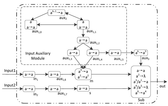
Figure 3.
The LHSNP system ПSub1 with 2 input neurons for two k-bit binary numbers subtraction.
The rules of ПSub1 are divided into 5 groups: (1) Homogeneous neurons: rule set Raux = {a → a} for auxiliary neurons, subtrahend neurons, and input neurons. (2) Minuend neuron σm uses rule set Rm = {a2 → a2, a3 → a}. (3) Spiking control neuron σaux2 uses rule set Raux2 = {ak−1 → a}. (4) Overflow monitoring neuron σaux3 uses rule set Raux3 = {ak → a5}. (5) Subtraction operator neuron σSub uses rule set RSub = {a → a; a2 → ƛ; a3/a2 → a; a4/a3 → ƛ; a6 → a4}.
The formal definition of ПSub1 is as follows:
where:
ПSub1 = (O, σin1, σin2, σaux1,0, σaux1,1, …, σaux1,7, σaux2, σaux3, σm, σs, σSub, syn, Input1, Input2, out)
- (1)
- O= {a};
- (2)
- σin1 = (0, Raux);
- (3)
- σin2 = (0, Raux);
- (4)
- σaux1,i = (1, Raux), 0 ≤ i ≤ 1;
- (5)
- σaux1,i = (0, Raux), 2 ≤ i ≤ 7;
- (6)
- σaux2 = (0, Raux2);
- (7)
- σaux3 = (0, Raux3);
- (8)
- σm = (0, Rm);
- (9)
- σs = (0, Raux);
- (10)
- σSub = (0, RSub);
- (11)
- syn = {(in1, aux1,6), (in2, aux1,7), (aux1,6, m), (aux1,7, s), (m, Sub), (s, Sub), (aux1,0, aux1,1), (aux1,1, aux1,0), (aux1,1, aux2), (aux2, aux1,0), (aux2, aux1,1), (aux1,1, aux1,2), (aux1,2, aux1,3), (aux1,2, aux1,4), (aux1,3, auxm), (aux1,4, auxm), (aux1,4, aux1,5), (aux1,5, aux3), (aux3, Sub)};
- (12)
- in1 = Input1, in2 = Input2;
- (13)
- out = Sub.
Through analysis ПSub1 and its rule set, we can see: ПSub1 contains 15 neurons and 9 rules, and completing the subtraction operation of 2 k-bit binary numbers requires a k + 4 time slice.
Theorem 3.
ПSub1 can perform any 2 k-bit binary numbers subtraction with 2 input neurons. Namely, after ПSub1 receives k-bit binary numbers in the order from low to high, it can correctly perform subtraction and output spiking to the environment in the order from low to high.
Proof of Theorem 3.
Let t represent the time slice. At the initial state t = 0, there is one spiking in σaux1,0 and σaux1,1. Starting from t = 1 time slice, two binary numbers are sequentially received by σin1 and σin2 from low to high. When the binary bit is 1, σin1 and σin2 received 1 spiking, otherwise 0 spiking were received. The minuend passes through σaux1,6 and σminuend passed to σSub participates in subtraction operations. Subtraction is passed in the order of σin1,7, σsubtahend, and σSub. The calculation process of ПSub1 is as follows:
- ①
- Input Auxiliary Module
The function of the input auxiliary module is to adjust the number of spiking corresponding to the binary number 0 represented by the minuend number during transmission. The purpose is to make the spiking representing the minuend and subtrahend corresponding to the binary number 0 different. The process for inputting auxiliary modules is as follows:
- (1)
- t = 0, there is one spiking in σaux1,0 and σaux1,1.
- (2)
- t = 1 to 2, the input auxiliary module does not generate spiking output. At each time slice, σaux1,0 and σaux1,1 send spiking to each other and maintain 1 spiking. At the same time, σaux1,0 at every time slice sends 1 spiking to σaux1,2. These spikings are transmitted along σaux1,2 and (σaux1,3, σaux1,4).
- (3)
- t = 3 to k + 2, the input auxiliary module does not send spiking output. σaux1,3 and σaux1,4 send one spiking to σminuend at each time slice. t = 3 to k − 1, σaux1,0 and σaux1,1 send spiking to each other. And σaux1,0 at each time sends 1 spiking to σaux1,2. At k − 1 time slice, k − 1 spikings stacked in σaux2. At t = k time slice, σaux1,0 and σaux1,1 received 2 spiking. One of the spiking comes from what they send to each other. Another spiking is sent by σaux2 using rule ak−1 → a. At k + 1 time slice, the spiking in σaux1,2 is cleared to zero. At k + 1 time slice, the spiking in σaux1,3 and σaux1,4 is cleared to zero.
- (4)
- At the k + 3 time slice, σaux1,5 send 1 spiking to σaux3. There are 8 spikings stacked in σaux3.
- (5)
- At the k + 4 time slice, the input auxiliary module no longer generates spiking.
- ②
- Minuend Input
- (1)
- t = 1 to k, the spiking corresponding to each binary bit of the minuend is sequentially received by σin1 in order from low to high. These spikings are transmitted along σaux1,6, σminuend, and σSub.
- (2)
- t = 3 to k + 2, the spiking corresponding to each binary bit of the minuend is sequentially received by σminuend. At the same time, σminuend also received 2 spikings at each time from σaux1,3 and σaux1,4.
- (3)
- t = 4 to k + 3, the spiking corresponding to each binary bit of the minuend sent by σminuend is sequentially received by σSub. At each time slice, one spiking sent by minuend represents the binary number 1, and 2 spiking represents the binary number 0. At k + 3 time slice, the highest bit of the minuend is received by σSub.
- ③
- Subtrahend Input
- (1)
- t = 1 to k, the spiking corresponding to each binary bit of the subtrahend is sequentially received by σin2 in order from low to high. These spikings are transmitted along σaux1,7, σsutrahend, and σSub.
- (2)
- t = 3 to k + 2, the spiking corresponding to each binary bit of the subtrahend is sequentially received by σsutrahend.
- (3)
- t = 4 to k + 3, the spiking corresponding to each binary bit of the subtrahend is sequentially received by σSub. At each time slice, one spiking sent by σsutrahend represents the binary number 1, and zero spiking represents the binary number 0. At k + 3 time slice, the highest bit of the subtrahend is received by σSub.
- ④
- Subtraction Operation
- (1)
- t = 1 to 3, there is no spiking were received in σsub.
- (2)
- t = 4 to k + 3, the spiking corresponding to each binary bit of the minuend and subtrahend sent by σminuend and σsutrahend are sequentially received by σSub.
- (3)
- t = 5 to k + 4, σsub sends calculation results to the environment at each time slice. It is the effective output time of ПSub1 when there is no overflow in the calculation. At t = k + 3 time slice, the highest bit of the two subtractors is calculated. At t = k + 4 time slice, σaux3 uses rule ak → a5 to send 5 spikings to σsub. These 5 spikings in the σsub detect whether there is a carry after the calculation of the highest bit of the two subtractions. If there is a carry generation, σsub uses rule a6 → a4 to send 4 spikings to the environment to indicate data overflow.
- ⑤
- Subtraction Rules
There are 5 rules in σSub represent subtraction operations. The situation of performing subtraction in σSub is as follows:
- (1)
- Rule a → a indicates performing subtraction calculation: 12 − 02 = 12. There is one spiking in σsub, which comes from σminuend. It represents the subtracted binary bit 1. Rule a → a represents consumption 1 spiking in σsub, and sending 1 spiking to the environment, namely performing subtraction operation 12 − 02 = 12.
- (2)
- Rule a2 → ƛ indicates performing subtraction calculation: 02 − 02 = 02 or 12 − 12 = 02. There are two spikings in the σsub, and there are three sources of these two spikings. In the first case, these two spikings have come from σminuend and σsubtrahend. In the second case, one of them come from σsub retained spiking in σsub (be borrowed), and the other one come from σsubtrahend. In the third case, these two spikings came from σminuend. Rule a2 → ƛ consumption 2 spikings in σsub, and send 0 spiking to the environment, namely performance subtraction operation 02 − 02 = 02 or 12 − 12 = 02.
- (3)
- Rule a3/a2 → a indicates performing subtraction calculation: 02 − 12 = 12 and borrowing one digit forward. Two spikings come from σminuend and one spiking comes from σaddend. Rule a3/a2 → a represents consuming 2 spikings in σsub, retaining 1 spiking (representing forward borrowing), and sending 1 spiking to the environment. That is, the subtraction operation performed is 02 − 12 = 12 and borrowing 1 digit forward.
- (4)
- Rule a4/a3 → ƛ means to perform subtraction: 02 − 12 − 12 = 02 and borrow 1 bit forward. Two spikings were sent by σminuend, one spiking was sent by σaddend, and one spiking was retained in σSub. Rule a4/a3 → ƛ means that 3 spikings in σSub are consumed, 1 spiking is reserved (representing forward borrowing), and 0 spikings are sent to the environment. That is, the subtraction operation is 02 − 12 − 12 = 02, and 1 bit is borrowed forward.
- (5)
- Rule a6 → a4 indicates that the highest bit of two binary numbers is carried during calculation in σsub, data overflow. A total of 5 spikings come from the σaux3 and 1 spiking comes from σsub reservation. Rule a6 → a4 means that 6 spikings in σsub are consumed and generate 4 spikings are sent to the environment, indicating data overflow.
In summary, ПSub1 can correctly calculate the difference between 2 k-bit binary numbers. □
In order to illustrate the operating process of ПSub1, take the difference between 13 and 7 as an example for explanation. Assuming the current system is 8-bit. The equation 13 − 7 = 6 is expressed as 000011012 − 000001112 = 000001102 in ПSub1. In the ПSub1 calculation process, the number of spiking in all neurons and the number of spikings sent to the environment at each time slice are shown in Table 4. In Table 4, “t” represents the time slice. “in1” represents the number of spiking in σin1. “in2” represents the number of spiking in σin2. “aux1,i (0 ≤ i ≤ 7)” represents the number of spiking in the auxiliary neuron σaux1,i. “aux2” represents the number of spiking in σaux2. “aux3” represents the number of spiking in σaux3. “m” represents the number of spiking in σminuend. “s” represents the number of spiking in σsubtrahend. “Sub” represents the number of spiking in σSub. “out” represent the number of spiking sent to the environment. The 2 k-bit binary numbers input and the calculation results are represented in bold font.
Table 4.
The number of spiking of all neurons in ПSub1 and the number of spiking sent to the environment during the calculation of 00001012 − 000001112 = 000001102.
The process of calculating the difference between 00001012 and 000001112 in ПSub1 is as follows:
- ①
- Input Auxiliary Module
- (1)
- At t = 0 time slice, there is one spiking in σaux1,0 and σaux1,1.
- (2)
- t = 1 to 7, σaux1,0 and σaux1,1 send 1 spiking to each other and maintain one spiking in. At the same time, σaux1,1 will send one spiking to σaux2 and σaux1,2. After receiving spiking, these spikings accumulate inside σaux2. And at t = 7 time slice, σaux2 accumulates 7 spikings. The spiking received by σaux1,2 is transmitted along three paths.
The first path: These spikings are transmitted along σaux1,3 to σm. At t = 3 time slice, σm receives the first spiking sent by σaux1,3.
The second path: These spikings are transmitted along σaux1,4 to σm. At t = 3 time slice, σm receives the first spiking sent by σaux1,4.
The third path: These spikings are sent to σaux3 along σaux1,4, σaux1,5. After receiving the spikings, σaux3 accumulates them in the neurons.
- (3)
- At t = 8 time slice, σaux1,0 and σaux1,1 sent 1 spiking to each other. And σaux1,0, σaux1,1 receives 1 spiking from σaux2 using rule a7 → a. At the same time, σaux2 received 1 spiking sent by σaux1,1. And when the system stops, there is only 1 spiking in σaux2.
- (4)
- At t = 9 time slice, σaux1,0 and σaux1,1 stop generating spiking. At the same time, the spiking in σaux1,2 is consumed.
- (5)
- At t = 10 time slice, σaux1,0, σaux1,1, …, σaux1,4 stop generating spiking.
- (6)
- At t = 11 time slice, 8 spikings sent by σaux1,5 are stacked in σaux3.
- (7)
- At t = 12 time slice, there are no rules to execute in the input auxiliary module.
- ②
- Minuend Input
The minuend number transmits along σin1, σaux1,6, σm to σsub. When minuend binary bits pass through σm, with the assistance of σaux1,3 and σaux1,4, the spiking corresponding to the transmitted binary number 0 is modified to 2, in order to distinguish it from the spiking corresponding to the subtracted number 0 in the σsub. The transmission of the minuend is as follows:
- (1)
- t = 1 to 8, the corresponding spiking of the minuend binary bits are sequentially received by σin1 in order from low to high.
- (2)
- t = 2 to 9, the corresponding spiking of the minuend binary bits are sequentially received by σaux1,6.
- (3)
- t = 3 to 10, the corresponding spiking of the minuend binary bits are sequentially received by σm. At each time slice, σm receives 2 spiking sent by σaux1,3 and σaux1,4.
- (4)
- t = 4 to 11, the corresponding spiking of the minuend binary bits are sequentially received by σsub. In σsub, 1 spiking represent binary number 1, and 2 spikings represent binary number 0.
- ③
- Subtrahend Input
Subtrahend are transmitted to σsub along σin2, σaux1,7 and σs. The transmission process of subtraction is as follows:
- (1)
- t = 1 to 8, the corresponding spiking of the subtrahend binary bit is sequentially received by σin2 in order from low to high.
- (2)
- t = 2 to 9, the corresponding spiking of the subtrahend binary bit is sequentially received by σaux1,7.
- (3)
- t = 3 to 10, the corresponding spiking of the subtrahend binary bit is sequentially received by σs.
- (4)
- t = 4 to 11, the corresponding spiking of the subtrahend binary bit is sequentially received by σsub. Subtrahend in σsub represents binary number 1 with 1 spiking, and 0 spiking represent binary number 0.
- ④
- Subtraction Operation
- (1)
- t = 1 to 3, there is no spiking in the σsub.
- (2)
- t = 4 to 11, the spiking corresponding to the minuend and subtracted binary bit is received by the σsub in order from low to high.
- (3)
- t = 5 to 12 is the effective output time of ПSub1. During this time slice, σsub sends the calculation result 0, 1, 1, 0, 0, 0, 0, 0, 0, 0 to the environment in order from low to high. At t = 12 time slice, σsub receives 5 spikings sent by σaux3 using rule ak → a5, and these 5 spikings are stacked in σsub, the calculation result did not overflow.
From Table 4, it can be seen that the operation results of the 2 natural numbers are 000001102, which is 6. The result is correct and verified that ПSub1 can correctly perform subtraction operations on two binary numbers.
4.2. An LHSNP System with 1 Input Neuron for 2 Number Subtraction
The LHSNP system ПSub2 with one input neuron that implements any two k-bit binary number subtraction is shown in Formula (6). The structure of the ПSub2 system is shown in Figure 4. In Figure 4, the solid arrows represents the directed connection between two neurons. The dashed arrows indicates the omission of connections between multiple neurons. The ПSub2 design idea is as follows: ① The system input part is divided into two modules, namely the input module and the minuend cache module. The input module consists of an input assist module and an input selection module. The input auxiliary module controls the transmission of the minuend through σaux4, and the subtrahend is transmitted through the subtrahend neuron σs. ② σmi (0 ≤ i ≤ k − 1) in the minuend catch module is used to cache the spiking corresponding to each bit of the minuend. When the minuend passes through σm0, with the assistance of the input auxiliary module, adjust the spiking represents the binary number 0 in σm0. The purpose is to distinguish the spiking corresponding to the subtrahend binary number 0 in σSub. ③ Minuend and subtrahend are calculated in the subtraction operation neuron σSub, and the operation results are sent to the environment in order from low to high. ④ Overflow monitoring neuron σaux5 marks the carry after the end of the highest-bit calculation in σSub. If there is a carry, it stands the calculation result overflows.
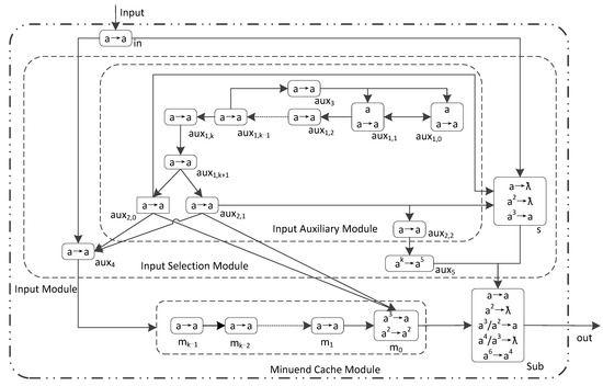
Figure 4.
The LHSNP system ПSub2 with 1 input neuron for 2 k-bit binary numbers subtraction.
The rules in ПSub2 are divided into 5 groups: (1) Homogeneous neurons: auxiliary neurons, minuend cache neurons (mi (1 ≤ i ≤ k − 1)), and input neurons with a rule set of R = {a → a}; (2) The rule set for minuend spiking adjustment neuron σm0 is Rm = {a2 → a2; a3 → a}; (3) Overflow detection neuron σaux5 use rule set Raux5 = {ak → a5}; (4) Subtrahend neuron σs use rule set Rs = {a → ƛ; a2 → ƛ; a3 → a}; (5) Subtraction operator neuron σSub use rule set RSub = {a → a; a2 → ƛ; a3/a2 → a; a4/a3 → ƛ; a6 → a4}.
The formal definition of this system is as follows:
where:
ПSub2 = (O, σin, σaux1,0, σaux1,1, …, σaux1,k + 1, σaux2,0, σaux2,1, σaux2,2, σaux3, σaux4, σaux5, σm0, σm1, …, σmk−1, σs, σSub, syn, Input, out)
- (1)
- O= {a};
- (2)
- σin = (0, Raux);
- (3)
- σaux1,i = (0, Raux), i = 0, 1;
- (4)
- σaux1,i = (1, Raux), i = 2, …, k + 1;
- (5)
- σaux2,i = (0, Raux), i = 0, 1, 2;
- (6)
- σauxi = (0, Raux), i = 3, 4;
- (7)
- σaux5 = (0, Raux5);
- (8)
- σm0 = (0, Rm);
- (9)
- σmi = (0, Raux), i = 1, 2, …, k − 1;
- (10)
- σs = (0, Rs);
- (11)
- σSub = (0, RSub);
- (12)
- syn = {(in, aux4), (in, s), (s, Sub), (aux4, mk−1), (m0, Sub), (aux1,1, aux1,0), (aux1,k−1, aux3), (aux1,k−1, aux3), (aux3, aux1,1), (aux3, aux1,0), (aux1,k + 1, aux2,0), (aux1,k + 1, aux2,1), (aux2,0, aux4), (aux2,1, aux4), (aux2,0, m0), (aux2,1, m0), (aux2,1, aux2,2), (aux2,1, s), (aux2,2, aux5), (aux5, Sub), (s, Sub)}∪{(aux1,i, aux1,i + 1), i ∈ {0, 1, …, k}}∪{(mi−1, mi), i ∈ {1, 2, …, k}};
- (13)
- in = Input;
- (14)
- out = Sub.
Analyzing ПSub2 and its rule set, it can be seen that ПSub2 contains 9 rules with 2k + 11 neurons, and completing 2 k-bit binary subtraction operations requires 2k + 3 time slices. Furthermore, we have the following conclusion:
Theorem 4.
ПSub2 can perform any 2 k (k ≥ 5) bit binary number subtraction operations with one input neuron. Namely, after receiving binary number spiking in order from low to high, ПSub2 can correctly perform subtraction and output the operation results to the environment in order from low to high.
Proof of Theorem 4.
Let t represent the time slice. When the initial state t = 0, there is one spiking in σaux1,0 and σaux1,1. Starting from t = 1, two binary subtractions are received by σin in order from low to high. When the binary bit is 1, σin receives 1 spiking, otherwise 0 spiking. The minuend bits are sequentially passed to σSub through σaux4 and the σmi (0 ≤ i ≤ k − 1) in the minuend cache module to participate in the subtraction operation. The subtrahend bits are sequentially passed to σSub through σs to participate in the subtraction operation. The calculation process of ПSub2 is as follows:
- ①
- Input Auxiliary Module
The function of the input assist module is to distinguish the subtrahend and the minuend and monitor whether the highest-bit calculation result in the σSub overflows. During the time from t = 1 to k + 1, the input auxiliary module does not generate spiking output. During this period, the spiking sent by σin is sent to the neurons of the minuend cache module via σaux4. And at the same time, rule a3 → ƛ is firing in σs. At time t = k + 2, σaux2,0 and σaux2,1, respectively, send 1 spiking to σaux4 to maintain at least 2 spiking in σaux4, thereby preventing the subtrahend bits input from σin from entering the neurons of the minuend cache module. At the same time, σs receives 1 spiking sent by σaux2,0 and σaux2,1, respectively, to maintain at least 2 spikings, So that the subtrahend bits input from σin enters σSub for subtraction operation. The operation process of the input auxiliary module is as follows:
- (1)
- t = 0, there is 1 spiking in σaux1,0 and σaux1,1.
- (2)
- t = 1 to k + 1, σaux1,0 and σaux1,1 send 1 spiking to each other and maintain one spiking. At the same time, σaux1,1 sends 1 spiking to σaux1,2 at each time slice, and these spiking will be transmitted sequentially along σaux1,2, σaux1,3, …, σaux1,k + 1. At time t = k − 1, σaux3 receives 1 spiking sent by σauxk−1. At t = k time slice, σaux1,0 and σaux1,1, respectively receive 1 spiking sent by each other, and σaux3 sent 1 spiking to σaux1,0 and σaux1,1. It truncate the input to the auxiliary module for continuous spiking generation. At time t = k, the spiking in σaux1,2 are cleared.
- (3)
- t = k + 2 to 2k + 1, the input auxiliary module will continue to generate spiking output. σaux2,0 and σaux2,1 send 1 spiking to σaux4, σm0, σms at each time slice. Send spiking to σaux4 to truncate the spiking corresponding to the subtraction bit and transmit it through σaux4. Send 1 spiking to σm0, respectively, to modify the spiking corresponding to the binary number 0 in the subtrahend number. Send spiking to the σms to transmit the subtraction through the σms. σaux2,1 also sends 1 spiking to σaux2,2 at each time slice, and σaux2,2 receives the spiking and sends it to σaux5, which accumulates in σaux5. Input the spiking in σaux1,3, …, σaux1,k + 1, σaux2,0 and σaux2,1 of the auxiliary module in each time slice and clear them sequentially. At t = 2k + 1 time slice, σaux2,0 and σaux2,1 stops generating spiking output.
- (4)
- t = 2k + 2, in the input auxiliary module, σaux2,2 send 1 spiking to σaux5. And the spiking in σaux2,2 is cleared. At this time, 8 spikings are accumulated in σaux5, and the input auxiliary module stops generating spiking inputs.
- (5)
- t = 2k + 3, there are no rules can be firing in the input auxiliary module.
- ②
- Minuend Input
The bits of the minuend sent by σin are passed to σSub through σaux4 and the σmi (0 ≤ i ≤ k − 1) in the minuend cache module to participate in the subtraction operation. At t = 1 to k time slice, all the minuend bits are received by σin. At t = 1 to k + 2 time slice, the minuend cache module does not generate spiking output. At t = k + 3 to 2k + 2 time slice, σs sends the minuend bits to σAdd at each time slice. The input process of the minuend is as follows:
- (1)
- t = 1 to k, the spiking corresponding to the minuend bits are received by σin in order from low to high. At t = k time slice, the input of the minuend is completed. At each time slice, these spikings are transmitted sequentially along σaux4, σsumk−1, σsumk−2, …, σsum0. At t = 2 to k + 1 time slice, σs receives the spiking sent by σin at each time slice. This part of the spiking is forgotten by the rule a → ƛ in σs.
- (2)
- t = k + 1 to 2k + 2, the corresponding spiking of the minuend is sequentially transmitted to σSub along σaux4, σsumk−1, σsumk−2, …, σsum0, while the spiking in the neuron is sequentially cleared. At t = k + 2 to 2k + 1 time slice, the corresponding spiking of the minuend is sequentially received by σsum0, and at the same time, σsum0 also receives 1 spiking sent by σaux2,0, σaux2,1 at each time slice. At t = k + 3 to 2k + 2 time slice, the spiking corresponding to the minuend bits are received by σSub in order from low to high. At t = 2k + 2 time slice, there is no spiking in the minuend cache module.
- ③
- Subtrahend Input
The bits of the subtrahend sent by σin are passed to σSub through σs to participate in the subtraction operation. At t = k + 1 to 2k time slice, all subtrahend bits are received by σin. At t = k + 3 to 2k + 2 time slice, σs sends the subtrahend bits to σSub at each time slice. The input process for subtrahend is as follows:
- (1)
- t = 1 to k + 1, σs does not generate spiking output.
- (2)
- t = k + 1 to 2k, the corresponding spiking of the subtrahend is received by σin in order from low to high. At t = 2k time slice, the subtrahend input is completed. At each time slice, these spikings are sequentially transmitted along σs to σSub.
- (3)
- t = k + 2 to 2k + 1, σs receives spiking sent by σin and 1 spiking sent by σaux2,0, σaux2,1 at each time slice.
- (4)
- t = k + 3 to 2k + 2, the spiking corresponding to the subtrahend is received by σSub in order from low to high. At t = 2k + 2 time slice, there is no spiking in σs.
- ④
- Subtraction Operation
- (1)
- t = 1 to k + 2, σSub has no spiking input.
- (2)
- t = k + 3 to 2k + 2, the spiking corresponding to the minuend and subtrahend bits received by σSub in order from low to high.
- (3)
- t = k + 4 to 2k + 3, σSub will send the settlement results to the environment in order from low to high. At t = 2k + 2 time slice, the highest order of the two subtractions is calculated in σSub. At t = 2k + 3 time slice, σSub receives 5 spiking sent by σaux5. If a carry is generated at 2k + 2 time slice, then there are 6 spikings in σSub. In the 2k + 4 time slice, the environment will receive 4 spikings sent by σSub after using rule a6 → a4, indicating data overflow. If there is no carry generation at 2k + 2 time slice, then there are 5 spiking in σSub without using any rules.
In summary, the LHSNP system composed of ПSub2 can correctly calculate the difference between two k-bit binary numbers. □
To illustrate the operation process of ПSub2, the difference between 13 and 7 is calculated. If the current system has 8-bit (i.e., k = 8), then 13 − 7 = 6 is represented as 000011012 − 000001112 = 000001102 in ПSub2. In the ПSub2 calculation process, the number of spiking in all neurons at each time slice and the number of spiking sent to the environment are shown in Table 5. In Table 5, “t” represents the time slice. “in” represents the number of spiking in σin. “aux1,i (0 ≤ i ≤ k + 1), aux2,i (0 ≤ i ≤ 2), aux3, and aux4” represent the number of spiking in the auxiliary neuron. “aux5” represents the number of spiking in the overflow monitoring neuron σaux5. “mi (0 ≤ i ≤ k − 1)” represents the number of spiking in the minuend auxiliary meridian element σmi (0 ≤ i ≤ k − 1). “s” represents the number of spiking in the subtrahend neuron σs. “Sub” represents the number of spiking in the subtraction operation neuron σSub. “out” represents the number of spiking sent to the environment. “m6, …, m1” indicates the omission of spiking from σm6 to σm1. “aux1,3, …, aux1,8” indicates the omission of spiking from σaux1,3 to σaux1,8. The 2 k-bit binary numbers input and the calculation results are represented in bold font.
Table 5.
The number of spiking of all neurons in ПSub2 and the number of spiking sent to the environment during the calculation of 000011012 − 000001112 = 000001102.
The process of calculating the difference between 000011012 and 000001112 in ПSub2 is as follows:
- ①
- Input Auxiliary Module
- (1)
- The spikingin the input auxiliary module is transmitted along σaux1,2, σaux1,3, …, σaux1,9, and they are all homogeneous neurons, so the cases of aux1,3-aux1,8 are omitted in Table 5. t = 0, σaux1,0 and σaux1,1 each have 1 spiking.
- (2)
- t = 1 to 7, σaux1,0 and σaux1,1 sends 1 spiking to each other. And σaux1,1 also sends 1 spiking to σaux1,2 at each time slice, and these spiking are transmitted sequentially along σaux1,3, σaux1,4, …, σaux1,9.
- (3)
- t = 7 to 14, σaux3 receives 1 spiking sent by σaux1,7 at each time slice, and these spiking are, respectively, sent to σaux1,0, σaux1,1 through σaux3 and stacked in it. At t = 8 time slice, σaux1,0, σaux1,1 receives 1 spiking sent by each other and 1 spiking sent by σaux3, truncating the continuous generation of spiking in the input auxiliary module.
- (4)
- t = 9 to 18, the spiking of σaux1,2, σaux1,3, …, σaux1,9, (σaux2,0, σaux2,1), σaux2,2 in the input auxiliary module are sequentially cleared. At t = 10 to 17 time slice, σaux2,0, σaux2,1 continuously generates spiking output, while σaux2,1 also continuously sends spiking to σaux2,2. After receiving the spiking, σaux2,2 continuously sends the spiking to σaux5 and accumulates it. At t = 18 time slice, there are 8 spiking stacked in σaux5.
- (5)
- t = 19, there are no rules to execute in the input auxiliary module.
- ②
- Minuend Input
The spiking in the minuend cache module is transmitted along σm7, σm6, …, σm0, and are all homogeneous neurons, the cases of m6–m1 are omitted in Table 5.
- (1)
- t = 1 to 8, the spiking corresponding to the minuend bits are received by σin in the order of 1, 0, 1, 1, 0, 0, 0, 0, 0. These spikings are transmitted sequentially to σSub along σaux4, σm7, σm6, …, σm0.
- (2)
- t = 2 to 9, the minuend bits are sequentially received by σaux4 and σs. During this time slice, the spiking received by σs is consumed by the forgetting rule a → ƛ.
- (3)
- t = 10 to 17, the minuend bits are sequentially received by σm0, and at each time slice σaux2,0 and σaux2,1 is also sent a spiking to σm0.
- (4)
- t = 11 to 18, the corresponding spiking 1, 2, 1, 1, 2, 2, 2, 2, 2, 2 of the minuend bits are sequentially sent to σsub.
- ③
- Subtrahend Input
The spiking corresponding to the subtrahend bits is received by σin in descending order and then transmitted along σs to the σsub. The transmission of the subtrahend is as follows:
- (1)
- t = 0 to 8, σs did not generate spiking output.
- (2)
- t = 9 to 16, the spiking corresponding to the subtrahend bits are received by σin in the order of 1, 1, 1, 0, 0, 0, 0, 0, 0 from low to high.
- (3)
- t = 10 to 17, the corresponding spiking of the subtrahend bits are sequentially received by σs. At the same time, σs also receives 1 spiking sent by σaux2,0, σaux2,1 at each time slice. σs has 3, 3, 3, 2, 2, 2, 2, 2 spiking in each time slice, using rule a2 → ƛ or a3 → a direction sends spiking to σsub.
- (4)
- t = 11 to 18, the spiking corresponding to the subtrahend bits 1, 1, 1, 0, 0, 0, 0, 0 is sequentially received by σsub.
- ④
- Subtraction Operation
At t = 12 to 19 time slice, σsub sequentially sends the calculation results to the environment. After the calculation of the highest bits of the two subtractions in σsub is completed, the spiking sent by σaux5 is used to detect whether there is a carry generation. If there is a carry generation, the rule a6 → a4 is used to send 4 spiking to the environment, indicating data overflow. The calculation process is as follows:
- (1)
- t = 1 to 11, σsub did not generate spiking output.
- (2)
- t = 11 to 18, the minuend and subtrahend bits are sequentially received by σsub, and σsub has 2, 3, 3, 2, 2, 2, 2, 2 spiking in each time slice.
- (3)
- t = 12 to 19, σsub sends the operation results 0, 1, 1, 0, 0, 0, 0, 0 to the environment in sequence. At t = 19 time slice, σsub received 5 spikings sent by σaux5, no rules can be used, and there is no data overflow.
From Table 5, it can be seen that the operation result of two natural numbers is 000001102 = 6, which is correct and verifies that the system can achieve subtraction operation.
4.3. An LHSNP System with 1 Input Neuron for n-Subtraction
ПSub2 can only perform subtraction operations on 2 k-bit binary numbers, which has limitations in practical applications. Therefore, we have made improvements to ПSub2. The improved LHSNP system ПSub3 with one input neuron can perform subtraction operations on any n k-bit numbers (k ≥ 5). The structure of ПSub3 is shown in Figure 5. In Figure 5, the solid arrows represents the directed connection between two neurons. The dashed arrows indicates the omission of connections between multiple neurons. Due to the similarity between ПSub3 and ПSub2, the formal definition of ПSub3 has been omitted.
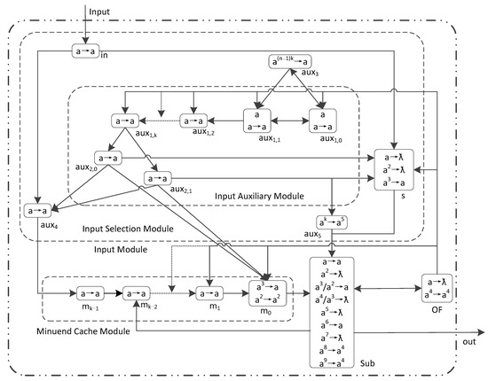
Figure 5.
The LHSNP system ПSub3 with 1 input neuron for n k-bit binary numbers subtraction.
The design idea of ПSub3 is as follows: ① The system input section consists of two modules, namely the input module and the minuend cache module. The input module consists of an input auxiliary module and an input selection module. The input auxiliary module controls the minuend number to be transmitted through σaux4, and the subtrahend number to be transmitted through σs. ② Spiking control neuron σaux3 controls σaux1,0 and σaux1,1 to stop generating spiking output. ③ When two subtrahends are performing subtraction operations in σsub, σsub sends the operation results to both the environment and the subtrahend cache module. The spiking waiting stored in the minuend cache module completes the subtraction operation with the next subtrahend in σsub to achieve accumulated subtract. ④ During the process of accumulating subtract, the high-order detection neuron σaux5 sends 5 spikings to detect whether the calculation results of the two highest orders of subtraction overflow. Five rules have been designed in σsub to determine whether the highest calculation result overflows. If the calculation result overflows, it sends 4 spikings each to the environment and overflow monitoring neuron σOF. ⑤ When the calculation result overflows, σOF will generate spiking output to truncate the transmission of spikings in ПSub3 and cause ПSub3 to stop running.
The rules in ПSub2 are divided into seven groups: (1) Homogeneous neurons: auxiliary neurons, minuend cache neurons σmi (1 ≤ i ≤ k − 1), and input neurons use rule set R = {a → a}. (2) Spiking control (neuron σaux3) uses rule set Raux3 = {a(n−1)k → a}. (3) Binary highest bit detection (neuron σaux5) uses rule set Raux5 = {ak → a5}. (4) Minuend spiking adjustment (neuron σm0) uses rule set Rm = {a2 → a2; a3 → a}. (5) Subtrahend (neuron σs) uses rule set Rs = {a → ƛ; a2 → ƛ; a3 → a}. (6) Subtrahend operator (neuron σSub) uses rule set RSub = {a → a; a2 → ƛ; a3/a2 → a; a4/a3 → ƛ; a5 → ƛ; a6 → a; a7 → ƛ; a8 → a4; a9 → a4}. (7) Overflow monitoring neuron (neuron σOF) uses rule set ROF = {a → ƛ; a4 → a4}.
Analyzing the structure diagram of ПSub3, it can be seen that ПSub3 contains 2k + 10 neurons with 15 rules, and completing the n k-bit binary number subtraction operation requires nk + 5 time slices.
To illustrate the operation process of ПSub3, an example is used to calculate the difference between 13, 15, and 8. If the current system is 8-bit, i.e., k = 8. Then 13 − 15 − 8 = −10 in the ПSub3 is represented as 000011012 − 000011112 − 000010002 = −000010102 (calculation result overflow). In the calculation process of ПSub3, the number of spiking in all neurons and the number of spiking sent to the environment at each time slice are shown in Table 6. In Table 6, t represents time slice. “in” represents the number of spiking sent by subtraction to neuron σin. “aux1,i (0 ≤ i ≤ k)” represents the number of spiking in auxiliary neuron σaux1,i (0 ≤ i ≤ k). “aux1,3, …, aux1,7” indicates omitting the number of spiking in the description σaux1,3, …, σaux1,7. “aux2,0, aux2,1” represents the number of spiking in the auxiliary neuron σaux2,0, σaux2,1. “auxi (3 ≤ i ≤ 5)” represents the auxiliary neuron the number of spiking in σauxi (3 ≤ i ≤ 5). “mi (0 ≤ i ≤ k − 1)” represents the number of spiking in the minuend auxiliary neuron σmi (0 ≤ i ≤ k). “m6, …, m2” indicates omitting the number of spiking in the description m6, …, m2. “s” represents the number of spiking in the minuend auxiliary neuron σs. “Sub” represents the number of spiking in the subtractive operation neuron σSub. “out” represents the number of spiking sent to the environment. “OF” represents the number of spikings in the overflow monitoring neuron σOF. The input n k-bit binary subtractions and calculation results are represented in bold font.
Table 6.
The number of spiking of all neurons in ПSub3 and the number of spiking sent to the environment during the calculation of 000011012 − 000011112 − 000010002 = − 000010102 (data overflow).
From Table 6, it can be seen that the operation result of the three natural numbers is 00112, which is correct and verifies that the system can perform subtraction operations.
The process of calculating the difference between 000011012, 000011112, and 000010002 in ПSub3 is as follows:
- ①
- Input Auxiliary Module
- (1)
- The spikings continuously sent by σaux1,1 in the auxiliary module are transmitted along σaux1,2, σaux1,3, …, σaux1,8. And these neurons are homogeneous neurons. So, we omit the description of the spiking situation of aux1,3, …, aux1,7 in Table 6. t = 0, there is 1 spiking in σaux1,0 and σaux1,1.
- (2)
- t = 1 to 17, σaux1,0 and σaux1,1 sends 1 spiking to each other. And σaux1,1 also sends 1 spiking to σaux3 at each time slice. These spikings are stacked in σaux3. At t = 16 time slice, σaux3 accumulates 16 spikings in neurons. σaux1,1 also sends 1 spiking to σaux1,2 at each time slice. And these spikings are transmitted sequentially along σaux1,3, σaux1,4, …, σaux1,8, (σaux2,0, σaux2,1). At t = 1 to 9 time slice, the input auxiliary module does not generate spiking output. At each time slice after t = 10, the input auxiliary module generates spiking output, σaux2,0 and σaux2,1 send one spiking to σaux4, σm0, σs at each time slice. At the same time, σaux2,1 also sends one spiking to σaux5, which is stacked in σaux5 until the number of spikings reaches 8. Then, use the rule a8 → a5 to consume spikings. At t = 17, σaux1,0 and σaux1,1 receive 1 spiking sent to each other. σaux3 uses rule a16 → a consume 16 spikings and generates 1 spiking output.
- (3)
- t = 18 to 22, σaux1,0, σaux1,1 no longer generates spiking output. The spikings in σaux1,2, σaux1,3, σaux1,4 are sequentially cleared. At t = 21 time slice, σaux1,0, σaux1,1, σaux1,2, σaux1,3, …, σaux1,8 simultaneously receives 4 spikings sent by σOF, truncating the transmission of spiking in the input auxiliary module.
- ②
- Minuend Input
The corresponding spiking of the minuend bit is received by σin and transmitted along σaux4, σm7, σm6, …, σm0 to the σsub. The transmission process of the minuend is as follows:
- (1)
- t = 1 to 8, the corresponding spiking of the minuend bit is received by σin, and these spikings are transmitted along σaux4, σm7, σm6, …, σm0.
- (2)
- t = 2 to 9, σin simultaneously sends spiking to σaux4 and σs. After receiving the spiking, σaux4 passes the spiking to the minuend cache module. After receiving spiking, σs does not generate spiking output, and these spiking are consumed by the forgetting rule a → ƛ in σs.
- (3)
- t = 10 to 17, the corresponding spiking of the first minuend bit is sequentially received by σm0. And at each time slice, σm0 also receives 1 spiking sent by σaux2,0 and σaux2,1. In σm0, the spiking corresponding to the minuend binary number 0 is changed to 2 through the rule a2 → a2, in order to distinguish it from the spiking corresponding to the subtrahend binary number 0.
- (4)
- t = 11 to 18, the spikings 1, 2, 1, 1, 2, 2, 2, 2 corresponding to the first minuend bit are sequentially received by σSub. A total of 1 spiking represents the minuend number 12, and 2 spikings represent the minuend number 02.
- (5)
- From t = 12 to the system stops, σm6 receives spikings (i.e., calculation results) sent by σSub at each time slice. And these spikings are transmitted along σm5, σm4, …, σm0 to σSub achieve accumulate plus with the next subtrahend. At t = 20 time slice, σm6 receives 4 spikings sent by σSub, and σm6 no longer generates spiking output in the following time. At t = 21 time slice, σm5, σm4, …, σm0 simultaneously receives 4 spikings sent by σOF. These spikings truncate the transmission of spiking in the minuend module. And σm6 receives 1 spiking sent by σSub.
- ③
- Subtrahend Input
The spiking corresponding to the subtrahend bit is received by σin and transmitted along σs to σSub. The transmission process of the subtrahend is as follows:
- (1)
- t = 1 to 8, σs does not generate spiking output. And the spiking σs received at each time slice has been consumed by the forgetting rule a → ƛ.
- (2)
- t = 9 to 16, the corresponding spiking 1, 1, 1, 1, 0, 0, 0, 0 of the first subtrahend bit are sequentially received by σin. These spikings are transmitted along σs to the σin.
- (3)
- t = 10 to 17, σs receives the spiking corresponding to the first subtrahend bit sent by σin. At the same time, σs receives 1 spiking sent by σaux2,0 and σaux2,1 at each time slice. σs uses rule a2 → ƛ or a3 → a to consume spikings and send spikings to σSub. From t = 10 to system stop, σaux4 receives spiking from σin, σaux2,0, and σaux2,1 at each time slice, these spikings are stacked in σaux4. t = 13 to 20, the spiking corresponding to each of the first subtrahend bits, 1, 1, 1, 1, 0, 0, 0, 0 are sequentially received by σSub. In a neuron, 1 spiking represents the binary number 12, and 0 spiking represents the binary number 02.
- (4)
- From 17 to 22, the spiking 0, 0, 0, 1, 0, 0 corresponding to the second subtrahend are received by σin. These spikings are transmitted along σs to the σSub. The transmission process is consistent with the first subtrahend. At t = 21 time slice, 4 spikings sent by σOF are received in σs, and the subtrahend transmission is truncated.
- ④
- Subtraction Operation
- (1)
- t = 1 to 10, σSub has no spiking input.
- (2)
- t = 11 to 18, the spiking corresponding to the first minuend and each subtrahend bit is received by σSub in order from low to high.
- (3)
- t = 12 to 19, σSub sends the calculation results to the environment, σOF, and σm6 simultaneously at each time. If σOF receives 1 spiking, it consumes the spiking by forgetting rule a → ƛ. After receiving the spiking in σm6, these spikings are transmitted along σm5, σm4, …, σm0 to the σsub to achieve accumulate subtract with the next subtrahend. At t = 19 time slice, the highest bit of the first minuend and subtrahend are received by σsub. And at the same time, σsub received 5 spikings sent by σaux5 after using the rule a8 → a5. At this time, σsub has 8 spikings.
- (4)
- t = 20, the environment, σOF, and σm6 receives four spikings sent by σSub after using rule a8 → a4. It represents data overflow. At the same time, 1 spiking sent by σm0 was received in the σSub.
- (5)
- At t = 21, σm5, σm4, …, σm0, σaux1,0, σaux1,1, …, σaux1,8, σs, σSub simultaneously receives 4 spikings sent by σOF after using rule a4 → a4. It truncates the transmission of spiking in ПSub3. At the same time, σSub sends 1 spiking to the environment, σOF, and σm6, respectively.
- (6)
- At t = 22, there are no rules can be fired in ПSub3.
4.4. Comparison
This section implements three different types of LHSNP systems ПSub1, ПSub2, and ПSub3 for subtraction. The three LHSNP systems designed in this article and the SN P system designed in [23] require the number of neurons, the time required to complete the operation, and the number of rules in the system, as shown in Table 7.
Table 7.
Three types of LHSNP system for subtraction.
The number of neurons required for ПSub1 is 15, and the time required to complete the calculation is k + 4. The number of rules involved in all neurons in the system is 9. Compared to the SN P system with 12 neurons and 4 rules for subtraction proposed by Zeng Xiangxiang et al. in [23], it has fewer rules and the structure is more concise.
The data of ПSub2 and ПSub3 are basically the same. The required number of neurons is 2k + 11 and 2k + 10. The required time to complete the calculation is 2k + 3 and nk + 5. The number of rules involved in all neurons in the system is 9 and 15. Since no SN P system with one input neuron for natural number subtraction has been found in existing references, comparative analysis will not be conducted.
5. Conclusions
Membrane computing as a parallel computing model has been applied in many fields in recent years. Because of the simplicity of the neuron structure, the spiking neural P system especially is considered to be the most promising membrane computing model for hardware implementation. One of the goals of spiking neural P system research is to use fewer neurons and simpler rules.
Based on this, this paper studies the LHSNP system for performing addition and subtraction. And we designed two kinds of LHSNP systems for addition and three kinds of LHSNP systems for subtraction that are performed on the eld of natural numbers. These five LHSNP systems are as follows:
- The LHSNP system ПAdd2 with 1 input neuron for any 2 k-bit binary number addition operation;
- The LHSNP system ПAdd3 with 1 input neuron for any n k-bit binary number addition;
- The LHSNP system ПSub1 with 2 input neurons for any 2 k-bit binary number subtraction;
- The LHSNP system ПSub2 with 1 input neuron for any 2 k-bit binary number subtraction;
- The LHSNP systemПSub3 with 1 input neuron for any n k-bit binary number subtraction.
The five LHSNP systems we designed achieved no delay in the system by adding neurons and were weightless from adding rule types. In this case, compared to other SN P systems, our designed LHSNP system reduces the time required to complete arithmetic operations while reducing system complexity. It improved system performance. At the same time, we considered the overflow of the performance results that make the LHSNP system have a higher application value.
In this work, we only studied the LHSNP system to perform addition and subtraction operations. Although multiplication and division can be realized by successive addition and subtraction. But it is more valuable to design an LHSNP system that can directly carry out multiplication and division.
Author Contributions
Conceptualization, R.L. and X.Z.; methodology, X.Z. and Z.H.; validation, R.L.; formal analysis, R.L. and J.L.; investigation, Z.H.; data curation, J.L.; writing—original draft preparation, R.L. and X.Z.; writing—review and editing, R.L. and Z.H. All authors have read and agreed to the published version of the manuscript.
Funding
This work was supported in part by the Natural Science Foundation Project of CQ CSTC (CSTB2023NSCQ-MSX0413).
Institutional Review Board Statement
Not applicable.
Informed Consent Statement
Not applicable.
Data Availability Statement
The data presented in this study are available in insert article.
Conflicts of Interest
The authors declare no conflict of interest. The funders had no role in the design of the study; in the collection, analyses, or interpretation of data; in the writing of the manuscript; or in the decision to publish the results.
References
- Păun, G. Computing with Membranes. J. Comput. Syst. Sci. 2000, 61, 108–143. [Google Scholar] [CrossRef]
- Zhang, G.-X.; Pan, L. A Survey of Membrane Computing as a New Branch of Natural Computing. Chin. J. Comput. 2010, 33, 208–214. [Google Scholar] [CrossRef]
- Ionescu, M.F.; Pǎun, G.; Yokomori, T. Spiking Neural P Systems. Fundam. Inform. 2006, 71, 279–308. [Google Scholar]
- Păun, G. Membrane Computing: An Introduction, 1st ed.; Huazhong University of Science & Technology Press: Wuhan, China, 2012; pp. 1–14. [Google Scholar]
- Zeng, X.; Zhang, X.; Pan, L. Homogeneous Spiking Neural P Systems. Fundam. Inform. 2009, 97, 275–294. [Google Scholar] [CrossRef]
- Wang, J.; Shi, P.; Peng, H.; Pérez-Jiménez, M.J.; Wang, T. Weighted Fuzzy Spiking Neural P Systems. IEEE Trans. Fuzzy Syst. 2013, 21, 209–220. [Google Scholar] [CrossRef]
- Song, T.; Pan, L.; Păun, G. Spiking Neural P Systems with Rules on Synapses. Theor. Comput. Sci. 2014, 529, 82–95. [Google Scholar] [CrossRef]
- Pan, L.; Wang, J.; Hoogeboom, H. Spiking Neural P Systems with Astrocytes. Neural Comput. 2011, 24, 805–825. [Google Scholar] [CrossRef] [PubMed]
- Zhang, G.; Rong, H.; Neri, F.; Pérez-Jiménez, M.J. An Optimization Spiking Neural P System for Approximately Solving Combinatorial Optimization Problems. Int. J. Neural Syst. 2014, 24, 1440006. [Google Scholar] [CrossRef] [PubMed]
- de la Cruz, R.T.A.; Cabarle, F.G.; Adorna, H.N. Generating Context-Free Languages Using Spiking Neural P Systems with Structural Plasticity. J. Membr. Comput. 2019, 1, 161–177. [Google Scholar] [CrossRef]
- Zhu, M.; Yang, Q.; Dong, J.; Zhang, G.; Gou, X.; Rong, H.; Paul, P.; Neri, F. An Adaptive Optimization Spiking Neural P System for Binary Problems. Int. J. Neural Syst. 2020, 31, 2050054. [Google Scholar] [CrossRef]
- Jiang, K.; Song, T.; Chen, W.; Pan, L. Homogeneous Spiking Neural P Systems Working in Sequential Mode Induced by Maximum Spike Number. Int. J. Comput. Math. 2013, 90, 831–844. [Google Scholar] [CrossRef]
- Peng, X.; Fan, X.; Liu, J.; Wen, H.; Liang, W. Small Universal Homogeneous Spiking Neural P Systems. J. Chin. Comput. Syst. 2013, 34, 1935–1939. [Google Scholar]
- Peng, X.; Fan, X.; Liu, J.; Wen, H.; Liang, W. Homogeneous Spiking Neural P Systems with Anti-Spikes. J. Chin. Comput. Syst. 2013, 34, 1949–1953. [Google Scholar]
- Peng, X.; Fan, X.; Liu, J.; Wen, H. Universal Homogeneous Spiking Neural P Systems without Delays. Comput. Eng. Sci. 2013, 35, 1–7. [Google Scholar]
- Paun, A.; Sosik, P. Three universal homogeneous spiking neural P systems using max spike. Fundam. Inform. 2014, 134, 167–182. [Google Scholar] [CrossRef]
- Song, T.; Wang, X. Homogenous Spiking Neural P Systems with Inhibitory Synapses. Neural Process. Lett. 2015, 42, 199–214. [Google Scholar] [CrossRef]
- Song, T.; Zheng, P.; Dennis Wong, M.L.; Wang, X. Design of Logic Gates Using Spiking Neural P Systems with Homogeneous Neurons and Astrocytes-like Control. Inf. Sci. 2016, 372, 380–391. [Google Scholar] [CrossRef]
- Liu, M.; Qi, F. Inhomogeneous Weighted Spiking Neural P Systems with Local Homogeneous. In Proceedings of the International Conference on Information Technology in Medicine and Education (ITME), Fuzhou, China, 23–25 December 2016; pp. 663–675. [Google Scholar]
- Yu, Y.; Wu, T.; Xu, J.; Wang, Y.; He, J. A Note on Spiking Neural P Systems with Homogenous Neurons and Synapses. Fundam. Inform. 2017, 150, 231–240. [Google Scholar] [CrossRef]
- de la Cruz, R.T.A.; Cabarle, F.G.C.; Macababayao, I.C.H.; Adorna, H.N.; Zeng, X. Homogeneous Spiking Neural P Systems with Structural Plasticity. J. Membr. Comput. 2021, 3, 10–21. [Google Scholar] [CrossRef]
- Paul, P.; Ghosh, S. On Label Languages of Homogeneous Variant of SNPSSP (HSNPSSP). In Proceedings of the 2022 IEEE 12th Annual Computing and Communication Workshop and Conference (CCWC), Las Vegas, NV, USA, 26–29 January 2022; pp. 0421–0427. [Google Scholar]
- Wu, T.; Zhang, L.; Lyu, Q.; Jin, Y. Asynchronous Spiking Neural P Systems with Local Synchronization of Rules. Inf. Sci. 2022, 588, 1–12. [Google Scholar] [CrossRef]
- Gutirrrez-Naranjo, M.A.; Leporati, A. Performing Arithmetic Operations with Spiking Neural P Systems. In Proceedings of the Seventh Brainstorming Week on Membrane Computing, Sevilla, Spain, 5–8 February 2009; pp. 181–199. [Google Scholar]
- Zhang, X.; Zeng, X.; Pan, L.; Luo, B. A Spiking Neural P System for Performing Multiplication of Two Arbitrary Natural Numbers. Chin. J. Comput. 2009, 32, 2362–2372. [Google Scholar]
- Chen, H.; He, Z. Signed Integer Arithmetic Operations in Spiking Neural P Systems. J. Comput. Inf. Syst. 2010, 6, 689–696. [Google Scholar]
- Zeng, X.; Song, T.; Pan, L.; Zhang, X. Spiking Neural P Systems for Arithmetic Operations. In Proceedings of the 2011 Sixth International Conference on Bio-Inspired Computing: Theories and Applications, Penang, Malaysia, 27–29 September 2011; pp. 296–301. [Google Scholar]
- Zeng, X.; Song, T.; Zhang, X.; Pan, L. Performing Four Basic Arithmetic Operations with Spiking Neural P Systems. IEEE Trans. Nanobiosci. 2012, 11, 366–374. [Google Scholar] [CrossRef]
- Peng, X.W.; Fan, X.P.; Liu, J.X. Performing Balanced Ternary Logic and Arithmetic Operations with Spiking Neural P Systems with Anti-Spikes. Adv. Mater. Res. 2012, 505, 378–385. [Google Scholar] [CrossRef]
- Peng, X.; Fan, X.; Liu, J.; Wen, H.; Liang, W. Spiking Neural P Systems with Anti-Spikes for Performing Balanced Ternary Logic and Arithmetic Operations. J. Chin. Comput. Syst. 2013, 34, 832–836. [Google Scholar] [CrossRef]
- Xu, Z.; Cavaliere, M.; An, P.; Vrudhula, S.; Cao, Y. The Stochastic Loss of Spikes in Spiking Neural P Systems: Design and Implementation of Reliable Arithmetic Circuits. Fundam. Inform. 2014, 134, 183–200. [Google Scholar] [CrossRef]
- Liu, X.; Li, Z.; Liu, J.; Liu, L.; Zeng, X. Implementation of Arithmetic Operations with Time-Free Spiking Neural P Systems. IEEE Trans. Nanobiosci. 2015, 14, 617–624. [Google Scholar] [CrossRef] [PubMed]
- Frias, T.; Diaz, C.; Sanchez, G.; Garcia, G.; Avalos, G.; Perez-Meana, H. Four Single Neuron Arithmetic Circuits Based on SN P Systems with Dendritic Behavior, Astrocyte-like Control and Rules on the Synapses. IEEE Lat. Am. Trans. 2018, 16, 38–45. [Google Scholar] [CrossRef]
- Wang, H.; Zhou, K.; Zhang, G. Arithmetic Operations with Spiking Neural P Systems with Rules and Weights on Synapses. Int. J. Comput. Commun. 2018, 13, 574–589. [Google Scholar] [CrossRef]
Disclaimer/Publisher’s Note: The statements, opinions and data contained in all publications are solely those of the individual author(s) and contributor(s) and not of MDPI and/or the editor(s). MDPI and/or the editor(s) disclaim responsibility for any injury to people or property resulting from any ideas, methods, instructions or products referred to in the content. |
© 2023 by the authors. Licensee MDPI, Basel, Switzerland. This article is an open access article distributed under the terms and conditions of the Creative Commons Attribution (CC BY) license (https://creativecommons.org/licenses/by/4.0/).