Review

A Review of Magnetoelectric Composites Based on ZnO Nanostructures

by
Achilleas Bardakas
1,2,*,
Andreas Kaidatzis
1 and
Christos Tsamis
1,*
1
Institute of Nanoscience and Nanotechnology, National Center for Scientific Research ‘Demokritos’, 15310 Athens, Greece
2
Physics Department, University of Patras, 26504 Patras, Greece
*
Authors to whom correspondence should be addressed.
Appl. Sci. 2023, 13(14), 8378; https://doi.org/10.3390/app13148378
Submission received: 14 June 2023 / Revised: 13 July 2023 / Accepted: 17 July 2023 / Published: 20 July 2023
(This article belongs to the Special Issue Micro- and Nanomanufacturing: From Nanoscale Structures to Devices)

Abstract

:
The recent advancements in magnetoelectric (ME) materials have enabled the development of functional magnetoelectric composites for sensor applications in the medical and engineering sectors, as well as in energy harvesting and material exploration. Magnetoelectric composites rely on the interaction between piezoelectric and magnetoelastic materials by coupling the magnetization-induced strain to the strain-generated potential of the piezoelectric phase. This creates an increased interest around the development of novel piezoelectric materials that not only possess favorable piezoelectric properties but also fulfill specific material criteria such as biocompatibility, bioactivity, ease of fabrication and low cost. ZnO, and its nanostructures, is one such material that has been employed in the magnetoelectric research due to its remarkable piezoelectric, semiconducting and optical properties. Thus, this article provides a comprehensive review of the available literature on magnetoelectric composites based on ZnO micro- and nanostructures, aiming to present a concise reference on the methods, applications and future prospects of ZnO-based ME composites. Specifically, a brief introduction is provided, presenting the current research interests around magnetoelectric composites, followed by a concise mention of the magnetoelectric effect and its key aspects. This is followed by separate sections describing the relevant research on ZnO magnetoelectric composites based on ZnO thin-films, either pure or doped, and nano- and microrods composites, as well as nano composites comprised of ZnO nanoparticles mixed with ferromagnetic nanoparticles. Finally, the future prospects and the extension of ME ZnO research into nanowire and nanorod composites are discussed.

1. Introduction

Magnetoelectricity, the coupling between electric polarization and magnetization, has been gaining increased scientific interest over the last few years since its first discovery in single-phase antiferromagnetic Cr2O3 at a low temperature [1]. Progress in multiferroic, ferromagnetic, ferroelastic and composite magnetoelectric materials has extended the reach of magnetoelectric composites into functional magnetoelectric devices [2,3,4], taking part in significant innovations in the sensor, medical and energy sectors [5,6,7,8]. The recent developments in magnetoelectric sensors based on novel materials and fabrication methods have made the detection of low intensity magnetic fields possible, reaching limits of detection previously achievable only by superconducting quantum interference devices (SQUIDs) [9]. Thin-film technology, in conjunction with the optimal combination of ferromagnetic and piezoelectric materials, has sparked the development of magnetoelectric sensors with high sensitivity at room temperature, compatibility with CMOS microfabrication, reduced fabrication cost and increased spatial resolution [10,11,12]. These properties make magnetoelectric sensors a promising candidate for biomagnetic measurements and imaging such as magnetocardiography (MCG), magnetoencephalography (MEG) [13] and magnetoneurography (MNG) [14].
In a recent review [15], the structure, fabrication, operation mechanism and noise analysis of thin-film magnetoelectric sensors for biomagnetic sensing were presented. Apart from the biomagnetic sensing and due to the inherent ability of magnetic fields to penetrate tissue non-invasively, magnetoelectric materials have the potential to facilitate the manipulation of important electrophysical effects at the subcellular level. The control of cell-to-cell interactions can be a significant catalyst in the development of advanced targeted treatments, enabled by magnetoelectric materials at the micro- and nanoscale. Recently, the application of magnetoelectric composites in drug delivery applications and cancer treatment, as well as in tissue engineering, brain stimulation and wireless energy transfer for implantable devices, were discussed in detail by Kopyl et al. [16], highlighting the prospects of magnetoelectric materials in future biomedical applications. Due to the coupling between ferromagnetic and piezoelectric domains, magnetostrictive materials and magnetoelectric composites were also employed in energy harvesting applications by exploiting both the direct and inverse magnetoelectric effect. Capturing the ambient energy available in the environment presents a viable method for powering the widespread adoption of the Internet of Things (IoT) in a decentralized and grid-independent way. Advancements in piezoelectric, magnetostrictive and magnetoelectric materials for energy harvesting emphasize the increased research interest in this area, which is highlighted in a recent review article [17], presenting the material, fabrication characterization and modelling achievements in the field. Based on the aforementioned applications and research efforts in micro- and nanofabrication, magnetoelectric composite research is mainly focused in material science and engineering, aiming to develop advanced composite structures with vastly different electrical, chemical and mechanical properties that allow the applicability of magnetoelectric materials in areas where biocompatibility, manufacturability, cost and magnetoelectric response are equally important. Currently, piezoelectric materials, including lead zirconate titanate (PZT), AlN, polyvinylidene fluoride (PVDF), AlScN, LiNbO3, etc., combined with FeGa, FeCoBSi, FeCo, Metglas (commercial alloys containing Fe, Co, Ni, B, Si) and Terfenol D (TbxDy1-xFe2) magnetostrictive materials, amongst others, have found widespread application in magnetoelectric composites and were studied extensively.
ZnO was also utilized as a piezoelectric phase in magnetoelectric composites not only due to its piezoelectric properties but also due to its inherent ferroelectric properties [18] and the plethora of micro- and nanostructures that it can be built into. Additionally, ZnO is a bio-compatible [19] and cost-effective material that can become a promising candidate for magnetoelectric devices for biomedical applications. Thus, this article presents a comprehensive review on magnetoelectric composites based on ZnO micro- and nanostructures, starting with a brief introduction of the magnetoelectric effect and its major concepts. The next sections elaborate upon the different categories of magnetoelectric composites based on ZnO, including thin-film structures, either pure or doped with metallic or ferromagnetic elements, or nano- and microrods based on magnetostrictive materials and nano composites comprised of ZnO nanoparticles (NPs) doped or mixed with ferromagnetic nanoparticles. A discussion section provides information regarding the current ME composites, including the future development prospects and potential applications of ZnO-based magnetoelectric composites, followed by conclusions.

2. Magnetoelectric (ME) Effect

The magnetoelectric effect (ME) originates from the coupling between electrical and magnetic phenomena in bulk, composite or multiphase materials. In particular, the direct magnetoelectric effect (DME) is defined as the emergence of an electric polarization P under the application of an external magnetic field H, whereas the converse ME effect (CME) is described as the emergence of or change in magnetization M when an external electric field E is applied [20]. ME composites rely on the interaction between a ferromagnetic (FM) phase exhibiting strain when subjected to a magnetic field due to magnetostriction and a piezoelectric (PE) phase that exhibits electric polarization via the application of mechanical stress/strain. The coupling between the electrical, magnetic and mechanical domains is given by the constitutive relations below in direct tensor notation [20]:
σ = cS - e T E - q T H   , D = eS + ε E + α H   , B = qS + α T E + μ H   ,
where σ, S and c are the stress, strain and stiffness tensors, respectively. D, E, ε and e denote the electric displacement field, electric field, electrical permittivity and piezoelectric coefficient tensors in the stress–charge form respectively. B, H, μ and q are the magnetic induction, magnetic field intensity, permeability and piezomagnetic coefficient, respectively, and α is the magnitude of the linear ME effect. Superscript T corresponds to the transpose of the tensor. The coefficients for the direct (αE) and converse (αH or αB) ME effects are conventionally used in the literature since they adequately describe the magnitude of the respective effects according to the “product property”, defined by the combination of PE and FM phases, and are used as a figure of merit describing the strength of the ME coupling [21]. Based on the “product property” definition, the direct ME coefficient is given by:
α E = δ E δ H   δ E δ S δ S δ H   , α E = V t   δ H   , α E = k c   q   e   ,
where V is the piezoelectric voltage generated across a PE material with thickness t under the application of magnetic field H with kc representing the electromechanical coupling between the FM and PE phases. The evaluation of the ME coefficient is usually performed in dynamic conditions by the application of alternating magnetic fields, thus, δE and δS are the amplitudes of the ac electric field and strain in a varying magnetic field δH. In addition, the ME coefficient includes the geometrical effects stemming from the configuration of the composite, the dependence of the magnetostriction λ of the ferromagnetic phase on H and the piezoelectric properties of the PE phase [16].
An important factor that greatly influences the ME response of a composite is its connectivity, which essentially specifies the way the FM and PE phases are interacting with each other, presented schematically in Figure 1. The connectivity is defined by two numbers, with the first one representing the FM phase and the second one the PE phase, indicating the number of coordinates along which strain transfer (i.e., deformation) occurs, from the magnetostrictive to the piezoelectric phase [22]. ME composites with 0-0 connectivity (Figure 1a) refer to a composite consisting of FM and PE particles embedded on a neutral matrix, while 0-3 composites (Figure 1b) consist of FM particles introduced to a PE matrix [23]. The connectivity type of 1-3 [24] indicate a rod, filament, tube or fiber type FM constituent in a PE matrix (Figure 1c). Planar and thin-film composites of the 2-2 type (Figure 1d) consist of alternating layers of FM and PE materials and are found in a variety of geometries ranging from the micro- to the nanoscale [25]. Advances in the realization of nanocomposites have also introduced more complex connectivity schemes, such as core-shell structures in nanoparticles (Figure 1e) and nanorods (Figure 1f) [26]. The material properties present a direct effect on the ME response since the ME coefficient depends both on the magnetostrictive and piezoelectric properties of the constituent phases, with dielectric constant, permeability, magnetostriction, coercive and anisotropy magnetic fields, remnant magnetization, electromechanical coupling and piezomagnetic and piezoelectric coefficients having a significant impact on the selection of an optimal material combination [21]. Regarding the PE phase, properties such as a high piezoelectric constant with low dielectric losses are favorable. For the FM phase, the increased piezomagnetic coefficient and high electrometrical coupling, along with the large saturation magnetostriction and large magnetic susceptibility, combined with soft magnetic properties, are favorable, especially for sensor applications [27]. A wide range of ferromagnetic materials were employed in magnetoelectric composites ranging from ferromagnetic metals with appreciable magnetostriction, such as Fe, Ni and Co, to ferromagnetic alloys, including FeCo [28], FeGa [29], FeGaB [30], FeCoBSi [27], Metglas and Terfenol-D, with enhanced piezomagnetic coefficients [31]. Additionally, cobalt and nickel ferrites (CFO, NFO) have found application mainly in magnetoelectric nanocomposites [32,33]. The piezoelectric constituents in ME composites consist commonly of PZT [34], AlN [35], ZnO [36], PVDF [37] and, more recently, AlScN [38] in thin-film form, 0-3 and 1-3 composites and nanostructures (nanoparticles, nanorods, etc.).

3. ZnO Magnetoelectric Composites
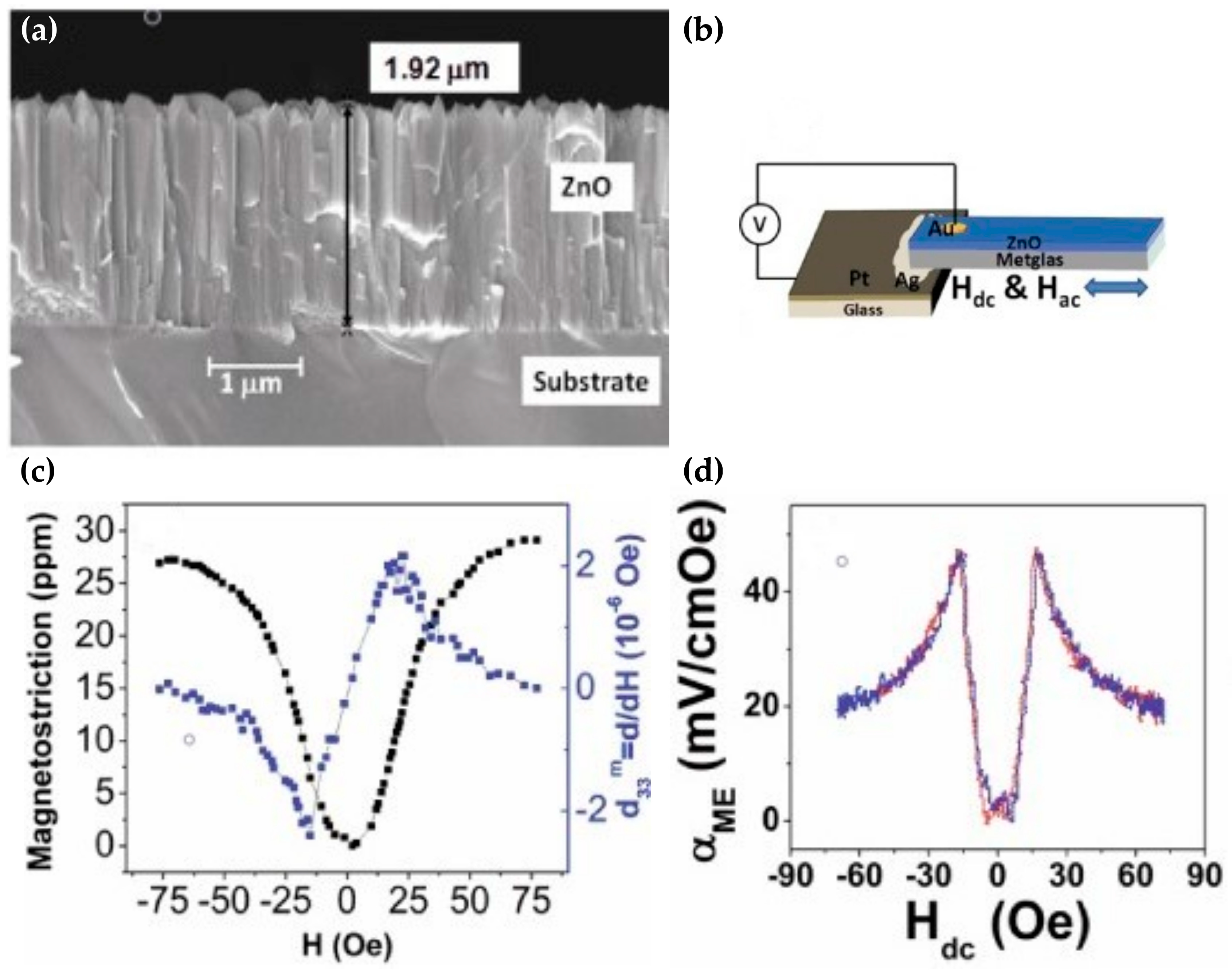
3.1. Thin Films

3.1.1. Pure ZnO Thin Films

ZnO thin films were extensively used in device applications [39] and, specifically, in chemical, optical and biological sensors [40] and light-emitting-diodes (LEDs) [41], as well as in thin-film transistors, gas sensors [42] and surface acoustic wave (SAW) devices [43]. Since ZnO is a well-established piezoelectric material with favorable piezoelectric and semiconducting properties [44], ZnO thin films have found widespread application in magnetoelectric composites. One of the first reports on ZnO thin-film magnetoelectric composites was presented by Viswan et al. [45], in which ZnO thin films were grown on Metglas substrates by pulsed laser deposition (PLD), as shown in Figure 2a, forming an ME cantilever with 2-2 connectivity (Figure 1d), depicted in Figure 2b. A highly c-axis-oriented ZnO film with a thickness of 2 μm was grown, presenting a columnar structure. Magnetoelectric characterization was performed using the DC and AC magnetic fields, and parameters such as the magnetostriction (λ), piezomagnetic coefficient d33,m and magnetoelectric coefficient αME were evaluated. A value of the saturation magnetostriction of 27 ppm at a magnetic field intensity of 60 Oe was measured with a maximum d33,m value of 2 ppm/Oe at a DC magnetic field of 17 Oe (Figure 2c). In addition, the evaluation of the direct ME (DME) (Figure 2d) and converse ME (CME) coefficient was included, showing a strong magnetic coupling between the ZnO piezoelectric phase and the Metglas substrate. Cantilever-based magnetoelectric devices represent the backbone of magnetoelectric detection and characterization since the introduction of the cantilever method by Klokholm [46] and its refinement by E. du Tremolet de Lacheisserie et al. [47]. In fact, tuning fork-like structures (two cantilevers) have shown remarkable sensitivity and a detection limit of 500 fT/(Hz)1/2 [27] utilizing PZT for the piezoelectric material at resonance.
Despite the widespread adoption of cantilever structures, ZnO-based ME research has also focused on SAW [48,49] in addition to bulk (BAW) and film (FBAR) bulk acoustic wave resonator devices [50], integrated with magnetostrictive materials. Alekseev et al. [51] presented a layered magnetoelectric heterostructure consisting of yttrium iron garnet (YIG) as the magnetostrictive phase grown on gadolinium gallium garnet (GGG) substrates. The ZnO thin-film layer used for the excitation of bulk, transversal and longitudinal acoustic waves was sputtered on top of the multilayer, with Al serving as the electrodes of the piezoelectric transducer. The influence of the external magnetic field on the BAW spectrum was studied at both low-intensity fields and at saturation. A shift in the acoustic resonance frequency was detected by increasing the field intensity from 0 to 100 Oe; however, only one of the shear modes was influenced, which was attributed to the polarization vector of that mode being parallel to the applied magnetic field. At saturating fields (0–2 kOe), an effective frequency tuning of 0.25 MHz at 2 GHz was observed due to the resonance magnetoelastic behavior in the YIG magnetostrictive film. Interestingly, it was also elaborated that the ferromagnetic resonance was detected without the application of an external rf magnetic field due to the electro-acoustical excitation provide by the ZnO piezoelectric transducer. In order to further investigate the characteristics of surface acoustic waves in magnetoelectric heterostructures, a theoretical investigation on the applicability of ZnO piezoelectric layers in magnetoelectric SAW devices was presented by Huang et al. [52], combined with Metglas magnetostrictive layers, shown in Figure 3a. The ZnO/Metglas ME composite showed a proposed 212 MHz/Oe magnetic field sensitivity, as depicted in Figure 3b, under an external bias of 0.9 Oe and a reduced sensitivity of −154 MHz/Oe at zero bias, suggesting a simpler device topology, eliminating the need of exciting coils. The increased magnetic field sensitivity is due to the giant ΔE effect [53,54] originating from the Metglas substrate, predicting a giant magnetic field sensitivity of 5 × 10⁻¹² T, while also allowing the detection of DC and AC magnetic fields due to the frequency independence for fields below several kHz.
The combination of the wave resonators with microelectromechanical systems (MEMS) in the field of magnetoelectrics offer the potential for sensor miniaturization and the integration of tunable and reconfigurable filter elements into microwave transceivers for mobile radios and RF SoCs (system-on-chip). Such a tunable, film bulk acoustic wave resonator was developed by Singh et al. [55]. The FBAR was fabricated on top of a bulk micromachined SiO2 membrane consisting of a Pt/ZnO/Fe65Co35 multilayer structure, utilizing the magnetostrictive phase as the second electrode of the piezo stack. Resonance peaks were detected at approximately 1.14 GHz (series resonance) and 1.19 GHz (parallel resonance) under unbiased conditions, with the application of a magnetic field resulting in a 7 MHz frequency downshift of both peaks, due to the ΔE effect. In a later study, Singh et al. [56] presented another FBAR with a frequency upshift of ~106 MHz (S11) at a magnetic field of 2 kOe, thus, demonstrating enhanced frequency tuning and a high ΔE modulus of 35.06 GPa compared to other reports [57]. Moreover, a MEMS ME magnetic field sensor was fabricated based on FeCo/ZnO thin films [58] utilizing a cantilever array and a film stack of Si/SiO2/Pt/ZnO/Pt/FeCo. At resonance (10.45 kHz), the magnetic field sensitivity was evaluated at 57.6 mV/Gauss. In addition, thin-film magnetoelectric composites were developed utilizing ferromagnetic and piezoelectric constituents deposited by a low temperature spin spray process [59]. The Fe3O4/ZnO heterostructure exhibited a large ferromagnetic resonance frequency shift of 14 Oe, with an ME coupling coefficient of 1.5 × 10⁻⁴ Oe cm k/V, demonstrating the viability of low-temperature deposition for static and microwave ME applications.
Magnetic-field-induced strain was also studied in ZnO/FeTb [60] and ZnO/FeCoBSi [61] thin-film systems via X-ray diffraction (XRD) and grazing incident X-ray diffraction (GIXRD), respectively. These characterization methods allow for the measurement of strain on the atomic scale by directly evaluating the lattice deformation of the ZnO crystal under an applied magnetic field bias. An analysis of the interface between ZnO and FeTb revealed the presence of substantial residual strain, which was attributed to the process of sample preparation and to the mismatch between the thermal expansion coefficients of FeTb and ZnO. The same procedure was used in order to evaluate the magnetostrictive induced strain in situ between 0 and 0.05 T (Figure 4b), showing an agreement with the cantilever bending measurements (Figure 4a) at a strain value of 3.7 × 10⁻⁴, validating the method for use in magnetoelectric characterization. In a similar fashion, the field-induced strain generated at the interface between ZnO and amorphous FeCoSiB was evaluated by GIXRD, showing tensile and compressive strains along the [110] and [1–10] of the ZnO crystal, as depicted in Figure 4d [61]. The magnetostriction measurements using the cantilever method (Figure 4c) were in good agreement with the magnetic-field-induced strain calculated by the shift of the ZnO (110) Bragg peak. GIXRD enables a more direct approach in residual and magnetic-induced strain in ME interfaces by providing the local average strain distribution (corresponding to the beam impinging area) and allowing strain mapping on the microscale.

3.1.2. Doped ZnO Thin Films

ZnO is an intrinsic n-type semiconductor with a substantial research effort focused on doping with appropriate impurities, such as lithium, copper and nitrogen as acceptors and aluminum, hydrogen and gallium as donors [62]. Doping with those impurities aims to either improve the n-type conductivity or switch the conductivity to p-type, which has proven quite challenging. For the case of magnetoelectric composites, the introduction of sub bands using shallow donors and acceptors or taking advantage of defects and vacancies were shown to induce ferromagnetism in ZnO films [63,64]. In addition, doping and the incorporation of non-ferrous metals such as Zn, Al, Pt and C into ZnO revealed ferromagnetic behavior due to p-p interactions between the 2p orbitals of O and C [65] and metal cluster formation into the ZnO matrix [66]. Magnetoelectric, W-doped, ZnO thin films were developed by physical vapor deposition (sputtering) using a ZnO target containing 1–2% tungsten in an Ar/O2 gas mixture (70/30%) at 420 °C [67]. The X-ray photoelectron spectroscopy studies revealed that the added W atoms were bonded with oxygen in the ZnO lattice, effectively substituting Zn+2 with W+6. This resulted in an increased carrier concentration due to the excess electrons provided by the bond between W+6 and O−2; however, an increase in room-temperature sheet resistivity and a reduction in mobility were observed. Magnetoresistivity was observed for both doped and pure thin films at low temperatures (5 K); however, no appreciable change in the magnetic properties of the W-doped thin films was observed. Doping with W does not appear to favor the enhancement of either magnetic or magnetoelectric properties; although metals such as Li, Ni and Mg were reported as potential dopants for enhancing the ferromagnetic and/or ferroelectric properties of ZnO thin films. In fact, Sharma et al. [68] presented the effect of Li, Ni and Mg doping on the magnetoelectric coupling and multiferroic properties of ZnO thin films. The pure and doped (5 wt.%) ZnO thin-films were synthesized by the sol-gel route using zinc acetate, lithium acetate, magnesium acetate and nickel nitrate as dopant sources. A non-linear ferroelectric behavior was identified in Ni-, Li- and Mg-doped samples, shown in Figure 5a,b, in contrast to pure ZnO, and the decrease in remnant polarization was attributed to the ionic radius of the dopants creating an electric dipole moment due to the substitution of Zn+2 in the crystal lattice. The magnetoelectric characterization, under a combination of AC and DC magnetic fields, resulted in magnetoelectric coupling in the Li-doped samples (Figure 5c) and increased magnetoelectric coupling in the Ni- and Mg-doped samples (Figure 5d,e) in contrast to pure ZnO. An enhanced ME voltage was observed in the Ni-doped samples due to the ferromagnetic nature of Ni.
As stated above, the un-doped ZnO shows weak reversible polarization. However, in a report by Maiz et al. [18], the ZnO nanorods depicted a clear polarization switching at a coercive field of 1400 MV/m. This was explained by the coexistence of two ZnO phases in the nanorod structure as a side-effect of the fabrication process, effectively creating a core-shell architecture. The samples that exhibited ferroelectricity presented an increased volume faction of the ZnO β-phase in contrast to samples crystallized only in the P63mc space group, thus, ferroelectricity in pure ZnO is a second-order effect rather than an intrinsic property of the material [69]. Therefore, doping strategies in ZnO were actively researched for their effect on the ferroelectric properties [70], especially in the case of ZnO doped with Li, Mg, Ni and Co. Lithium and Cobalt doped ZnO thin films were reported by Lin et al. [71] to exhibit simultaneous ferromagnetic and ferroelectric behavior, which was attributed to the Co2+ and Li+ ions occupying the off-center positions in the ZnO crystal. Both effects are defect-related, inducing permanent local electric dipoles in the case of ferroelectricity due to the different ionic radii of Li+ and Zn2+ ions. The magnetoelectric properties of the composite were not discussed in the aforementioned study; however, multiferroic composite materials that combine ferromagnetic and ferroelectric properties are highly effective for magnetoelectric applications [72]. In addition, the incorporation of ferromagnetic materials into ZnO thin films was investigated by Li et al. [73] via Co ion implantation of pulsed-laser-deposited ZnO films. The magnetoelectric coupling was established by the interaction between the electric dipole moments and magnetic moments, notably without strain-mediated effects due to the magnetostriction of the Co nanoparticles. Although the ME coupling was established at high-intensity magnetic fields, such a multiferroic nanocomposite thin film can present an alternative to conventional ME composites and be a possible candidate in magnetoelectric applications.

3.2. ZnO Micro- and Nano-Rods

In 2008, Chen et al. [74] demonstrated one of the first magnetoelectric composites utilizing ZnO nanorods for the piezoelectric phase and a Ni-Fe alloy for the magnetostrictive layer, corresponding to the connectivity scheme shown in Figure 1f. The ZnO nanorods were fabricated via the electrochemical deposition method on ITO substrates, depicted in Figure 6a, using an aqueous solution of zinc nitrate, KCL and formamide. A thin-film passivation layer was realized in order to electrically isolate the ITO substrate from the magnetostrictive layer- by spin coating a sol-gel-derived ZnO layer. The magnetostrictive Ni-Fe (75–25% wt.) phase was deposited on top of the as-grown nanorods by DC magnetron sputtering at a 5 × 10⁻³ Torr Ar ambient with a final thickness of 100 nm, shown in Figure 6b,c. The magnetoelectric characterization was performed by the direct ME measurement method, using an Au sputtered top electrode and the ITO substrate, via a lock-in amplifier in both longitudinal (LM) and transverse (TM) magnetization. The ME voltage coefficients (αH) for TM and LM (Figure 6d) were found to be 0.34 and 0.48 mV cm−1 Oe−1. Due to the shape anisotropy of the ZnO nanorods, the demagnetization factor D for fields perpendicular to the axis of the nanorods is larger than when the field is applied along the longitudinal axis [75], resulting in enhanced ME coupling and a larger ME voltage coefficient along the axis of the nanorods. Compared to the PZT and AlN piezoelectric phases, ZnO is an n-type semiconductor with a wide range of resistivity values [62] depending on the fabrication methods and annealing conditions. The lower ME voltage can be attributed to the leakage current, which is minimized in piezoelectric materials such as PZT with high resistivity values that present larger values of ME voltage coefficients [15]. The interfacing of magnetostrictive materials with nano- and microrods has proven to be a significant technological challenge due to the imperfections that exist on the interfaces, becoming the dominant factor for reduced ME performance. This is contrary to large ME laminates, where mechanical effects such as shear stresses and anchor losses can significantly influence sensitivity and performance.
The ZnO microrods were used by Kaps et al. [26], who developed a magnetoelectric core-shell composite based on amorphous FeCoBSi, focusing on the investigation of the interface between the two materials. The microrods with a length of up to 1 cm were synthesized via the modified vapor–liquid–solid (MVLS) approach and by the conventional vapor–liquid–solid (VLS) method. The FeCoBSi magnetostrictive thin film was RF sputtered on the VLS-grown rods, and the composite was investigated by TEM. The crystallinity of the ZnO microrods was not affected by the deposited magnetostrictive layer, which was of uniform thickness and amorphous in nature. Investigation of the interface can provide insight about the magnetization-induced stress and strain created through the interaction of the magnetostrictive and piezoelectric phase under the application of an external magnetic field [76]. Additionally, mechanical stress gradients may induce domain wall motion, even in the absence of an applied magnetic field or spin-polarized current. For example, a piezoelectric material generating stress may induce anisotropy in the magnetostrictive layer of an artificial multiferroic to generate domain wall motion [77]. Thus, utilizing the conventional methods of magnetic behavior characterization such as vibrating sample magnetometry (VSM) or the observation of mechanical effects due to strain (cantilever bending method) [46] cannot provide detailed distributions of strain and magnetization at the nanoscale. Magneto-optic Kerr effect (MOKE) microscopy was applied to ZnO microrod and nanorod [78] ME composites in order to investigate the magnetic domain structure, alignment and domain wall motion [79]. Domain wall rotation was observed on single microrod composites, shown in Figure 7a, with the application of a magnetic field perpendicular to the rod axis. Initially, the FeCoBSi MS layer is largely in a demagnetized state and, by the application of a transversal field, 180° domain wall motion occurs, reaching saturation above 15 mT. The complex magnetic domain structure can be identified from the demagnetized to the saturated state, suggesting the existence of magnetic domains with antiparallel alignment terminated by 90° domains along the [001] direction, which are gradually annihilated through the magnetization process, reaching a complete alignment along the direction of the applied field at saturation (Figure 7b). Although MOKE microscopy provides a detailed analysis of the magnetic domain structure, it does not provide any information regarding the magnetization-induced strain on the interface. For that purpose, X-ray diffraction (XRD) was utilized in order to observe the ZnO lattice deformation that occurred due to the external magnetic field.
Employing XRD as a means to evaluate magnetostriction allows us to probe microrods at a fine enough volume to allow for the spatial mapping of the lattice parameters with high resolution, both for the uncoated and coated samples, providing growth and magnetically induced strain information. In a study by Hrkac et al. [79], the combined MOKE and nano-diffraction studies revealed a magnetic easy axis perpendicular to the rod axis and magnetic-field-induced strains at the edges of the ZnO crystal exceeding the expected theoretical value of 4 × 10⁻⁵. This enhancement is unique to these microscopic systems due to geometrical considerations, as well as due to the contribution from the deposition induced compressive strain. In a future study by Hrkac et al. [80], a systematic study of FeCoSiB/ZnO microrod composites is presented (Figure 7d), utilizing nano-XRD (nXRD), shown in Figure 7c,f. Flame transport synthesis was used in order to produce mm-length ZnO microrods [81] that are covered entirely by a 500 nm thick (Fe90Co10)78Si12B10 film, deposited by RF magnetron sputtering. The analysis revealed a direct correlation between the magnetically induced strain and the diameter of the rods, which also occurs when studying the intrinsic strain induced by the deposition (Figure 7e). In both cases, the strain increases by reducing the diameter of the rod to a maximum of −5 × 10⁻⁵, which presents a 25% increase in comparison to the bulk ZnO ME composites [61]. This investigation of strain distribution directly on the interface between ZnO and an MS layer highlights the impact of miniaturization on ME composites and drives the research to pursue further improvement on magnetoelectric performance in the nanoscale. Recent studies aiming to discover ZnO magnetoelectric applications have also utilized the aforementioned nXRD method for investigating local strain distributions at the interface [82,83].
ZnO rods were also employed in the fabrication of magnetoelectric sensors based on the piezotronic effect, a remarkable combination of the semiconducting and piezoelectric properties of ZnO micro- and nanorods [84,85]. Using the same FTS method as in [80], Gröttrup et al. [36] synthesized mm-long ZnO micro needles (Figure 8b) and fabricated one of the first piezotronic-based magnetoelectric sensors (2-1 connectivity, rod-like PE phase on FM-thin-film) on a FeCoSiB cantilever, shown in Figure 8c. By using the piezotronic principle and piezotronic current measurements with Ohmic contact, an improvement by three orders of magnitude in the limit of detection (LoD) was demonstrated compared to sensors based on the piezoelectric measurements with Schottky contacts (Figure 8d,e). One important outcome is that ZnO resistivity and contact characteristics are essential parameters when considering piezotronic-based devices, as it was shown that the piezotronic current increases while the internal resistance decreases, which is a significant limiting factor of LoD performance. In addition to sensor application, ZnO was also utilized in photocatalytic applications [86], which, when coupled with magnetostrictive materials and visible light irradiation, can induce enhanced photocatalytic degradation of pollutants and increase the disinfection efficiency via the generation of oxygen and hydroxyl radicals [87].

3.3. ZnO Nanocomposites

As discussed above, thin-film- and micro/nanorod-based ZnO magnetoelectric composites rely on strain transfer between the magnetostrictive and piezoelectric phase for magnetoelectric coupling. On the other hand, nanocomposites are essentially a single-phase material where the magnetoelectric coupling arises from the interaction between magnetization and electric polarization in the volume of the material [88]. Magnetostriction is induced in the magnetic domains during magnetization, which involves domain movement that spontaneously induces an electrical polarization due to the piezoelectric effect. Cobalt-doped (Co-doped) ZnO nanoparticles were developed by Samanta et al. [89] via a chemical precipitation method using zinc acetate and cobalt acetate tetrahydrate as precursors, oxalic acid as the precipitating agent, ammonium hydroxide as a pH buffer and tetraethylammoniumhydroxide as an anti-agglomeration agent. The resulting nanopowder exhibited nano-crystalline domains of ZnO and Co3O4 with diffraction peak intensities modulated by Co content for both ZnO and Co3O4, accompanied by a reduction in the crystallite size, indicating the substitution of Co+2 at the Zn+2 sites. Ferromagnetic behavior was observed in the Zn-Co-O nanocomposites at 5K and was attributed to the exchange interaction of d-d coupling cobalt ions. In addition, oxygen vacancies heavily contribute to the reported ferromagnetism via a bound magnetic polaron (BMP), formed between trapped electrons by an oxygen vacancy and the trapped electron at an orbital overlapping with the d shell of a cobalt ion. Oxygen vacancies are identified in the doped samples by energy dispersive X-ray spectroscopy (EDS) and UV-visible and fluorescence (FL) spectra. The magnetoelectric coupling was verified by measuring the ME coefficient using the dynamic method, i.e., the measurement of the ME voltage developed across the sample under the simultaneous application of DC and AC magnetic fields. The magnitude of the magnetoelectric coefficient was evaluated at 8.65 mV/cm Oe at a magnetic field of 2 kOe for the Zn0.82Co0.18O sample, suggesting that the 18% Co-doped ZnO nanocomposites can be applied to functional device applications. Ferromagnetic ordering, due to the inherent oxygen vacancies and BMP formation, was also reported in Mg-doped ZnO nanoparticles (Figure 9a,b) [90] where an ME voltage coefficient of 4.13 mV/cm Oe was identified, depicted in Figure 9d. Another ferromagnetic material used in ZnO nanocomposites stems from the combination of Ni and Co with Fe2O4 (ferrite). Nickel ferrite (NiFe2O4) composites were developed by Dutta et al. [32], presenting room-temperature magnetoelectric voltage coefficients from 3.7 to 8 mV/cm Oe (Figure 9c,e). A similar magnetoelectric response was reported from La0.7Sr0.3MnO3–ZnO nanocomposites, presenting a maximum ME voltage coefficient of 2.6 and 2.4 mV/cm Oe for the transversal and longitudinal modes, respectively [91]. On the other hand, cobalt ferrite (CoFe2O4, CFO)–ZnO nanocomposites exhibited magnetoelectric coupling, which was evaluated through magnetocapacitance measurements at different frequencies and magnetic-field intensities. ME coupling mainly originated from strain effects due to the interaction of CFO and ZnO, inducing electrical polarization in the ZnO crystal via magnetostriction [33].

3.4. Discussion

In recent years, there has been substantial research interest in magnetoelectric composites destined for sensor applications, energy harvesting and energy transfer with a heightened interest in applications in biology, medicine and medical diagnostics. The bulk of this effort focuses on developing magnetoelectric composites with enhanced piezomagnetic coefficient, i.e., increased magnetostriction and piezoelectric constants, coupled with low coercivity magnetostrictive materials offering a narrow ferromagnetic resonance response. Advanced thin-film ME composites based on PZT, AlN and AlScN are undoubtedly some of the best performing composite structures, having achieved detections limits as low as a few pT Hz−1/2 at low frequencies. Furthermore, several reports have focused on improving the noise performance using magnetic and electric frequency conversion techniques [92,93], allowing for miniaturization, high frequency operation and increased immunity from environmental noise (mechanical vibrations, acoustic noise, etc.). However, thin-film technology relies predominately on advanced preparation methods such as physical and chemical vapor deposition (PVD and CVD) and requires access to semiconductor grade equipment, presenting an increased barrier of entry. In addition, the aforementioned piezoelectric thin films are not biocompatible, thus, in vivo testing and integration in implantable devices requires extensive encapsulation for reliable and safe operation [16].
On the other hand, ZnO-based magnetoelectric composites have the potential to extend the applicability of ME composites in demanding applications while also providing alternative routes for ME material fabrication and are able to fulfill requirements such as bio-compatibility, bioactivity and controllable dissolution in transient electronics [94]. On that front, one of the most important and interesting properties of ZnO is its low toxicity and biodegradability, owning to the important role that Zn+2 plays in human health [95]. In addition, the chemically active surface of ZnO can be functionalized and decorated by a number of chemical compounds due to the presence of OH radicals. Due to these properties, ZnO has gained ground in antimicrobial coatings for biomedical applications [96,97] and in biosensors [98]. More specifically, ZnO and its nanostructures were utilized in electrochemical biosensors [99] and optical and field effect transistor-based biosensors, as well as in biosensors leveraging its piezoelectric properties [100].
ZnO and its nanostructures [101] (nanowires/rods, nanoparticles, nanoribbons, etc.) were widely studied, owing to their exceptional piezoelectric, semiconducting and optical properties. Research efforts have also focused on the fabrication methods of ZnO nanostructures, showing that in addition to the common thin-film form factor, ZnO can be engineered into many different forms, utilizing either high-cost (CVD, ALD, etc.) or low-cost chemical routes. This versatility was leveraged into creating ME composites based on ZnO thin films, either doped or pure, micro/nanorods and nanocomposites combined with magnetostrictive materials, which were presented in this review. A summary of the available technologies used in ZnO-based ME composites is presented in Table 1.
Another advantage for using ZnO compared to other materials is its ability to dissolve in weak acids, bases and water, which is a highly desirable property for the emerging transient and dissolvable electronics. In fact, biocompatible transient electronics and energy harvesters based on ZnO were demonstrated [102,103,104], showing the potential of ZnO in advanced transient applications [105]. Essentially, by combining the favorable transient and biodegradable properties of ZnO with biocompatible ferromagnetic elements such as Mg [102], biocompatible magnetoelectric composites can be realized, with potential applications in biomagnetic imaging, energy and data transfer for implantable devices, drug delivery and body function monitoring and sensing.
Last, but not least, the exploitation of ZnO, as a piezoelectric phase, opens the possibility of developing a new generation of devices based on the piezotronics and piezophototronic phenomena. As was demonstrated by Wang et al. [106], it is possible to control carrier transport across a metal-semiconductor interface through the piezoelectric charges that are generated upon an external mechanical stress. This phenomenon is complementary to the change in resistance that appears in piezoresistive materials, such as ZnO, although it is not easy to identify the contribution of each mechanism. Zhu et al. [107] demonstrated the significance of the piezotronics effect over the change of piezoresistance; however, further research is required to better clarify this point.
Despite the successful integration of ZnO nanostructures with magnetostrictive materials, a gap still exists between state-of-the-art ME materials and ZnO-based ME composites in terms of piezomagnetic and ME coefficients. To improve the ME performance, the coupling between the FM and PE phases of the composites needs to be maximized, combined with advanced magnetostrictive materials with improved magnetostriction and soft magnetic behavior. Moreover, ZnO nanowires and nanorods have not yet been fully explored in magnetoelectric applications, even though they represent the bulk of research around ZnO nanostructures. Until this point, only ZnO microrods were extensively utilized in the study of the interfacial interaction between ZnO and magnetic materials, [61,80,82,83], specifically targeting sensor applications. Thus, a novel application of nanowire/nanorod composites, either in array form or in single nanowire configurations, may provide the means of bridging the performance gap, while also improving upon spatial resolution and sensitivity in sensor applications. Single ZnO nanowire-based magnetoelectric composites are still missing from the literature and, combined with the piezotronic and the piezophototronic effect [86], can potentially improve upon the performance of current ZnO ME composites but also give rise to new effects through the interaction between ferromagnetism, photoexcitation, piezoelectricity and the semiconducting phenomena in ZnO.

4. Conclusions

In this review, we highlighted the research and development on ZnO-based magnetoelectric composites in various forms, including thin films, micro- and nanorods and nano composites. Although several materials are utilized for exploiting ME phenomena, ZnO presents significant interest due to its unique properties, including biocompatibility, non-toxicity, low-cost fabrication and potential applicability in large area electronics. A significant portion of the research effort focuses on the integration of ZnO micro- and nanostructures with advanced magnetostrictive materials for the realization of novel ME heterostructures. ZnO thin films were utilized extensively in the fabrication of ME composites as the piezoelectric constituent, in diverse device architectures ranging from cantilevers, surface acoustic waves (SAW) and bulk acoustic waves (BAW) devices, to MEMS FBAR and microcantilever sensors. In addition, thin-film characterization methods such as XRD and GIXRD have enabled us to assess magnetostrictive strain at the atomic scale, something that can be leveraged extensively in ME research beyond ZnO. Furthermore, the doping of pure ZnO films can induce ferromagnetic properties with an enhanced magnetoelectric response, while suitable co-doping results in ferroelectric and ferromagnetic phenomena that can simultaneously exist in ZnO thin films. ZnO micro- and nanorod composites, on the other hand, constitute the most promising route for ME composites based on ZnO. This is supported by the fact that there is already substantial research around the basic electronic and structural properties of these structures, and by combining them with advanced magnetostrictive materials, this can lead to novel architectures suitable for sensing, biomedical applications and energy harvesting, in conjunction with the introduction of new effects stemming from the interaction between ferromagnetism, photoexcitation, piezoelectricity and semiconducting phenomena.
Further research into the combination of magnetostrictive materials with ZnO nanostructures, especially micro- and nanorods, will pave the way for a new generation of devices able to detect extremely low magnetics fields suitable for portable devices and personal health care applications.

Author Contributions

Conceptualization, A.B. and C.T.; methodology, A.B. and C.T.; writing—original draft preparation, A.B.; writing—review and editing, A.B., A.K. and C.T.; visualization, A.B.; funding acquisition, C.T. All authors have read and agreed to the published version of the manuscript.

Funding

This research is co-financed by Greece and the European Union (European Social Fund-ESF) through the Operational Program «Human Resources Development, Education and Lifelong Learning» in the context of the project “Strengthening Human Resources Research Potential via Doctorate Research–2nd Cycle” (MIS-5000432), implemented by the State Scholarships Foundation (ΙΚΥ).

Institutional Review Board Statement

Not applicable.

Informed Consent Statement

Not applicable.

Data Availability Statement

Not applicable.

Acknowledgments

The authors acknowledge A. Segkos for a thorough reading of the manuscript.

Conflicts of Interest

The authors declare no conflict of interest.

References

  1. Astrov, D.N. Magnetoelectric Effect in Chromium Oxide. Sov. Phys. JETP 1961, 13, 729–733. [Google Scholar]
  2. Piorra, A.; Jahns, R.; Teliban, I.; Gugat, J.L.; Gerken, M.; Knöchel, R.; Quandt, E. Magnetoelectric Thin Film Composites with Interdigital Electrodes. Appl. Phys. Lett. 2013, 103, 032902. [Google Scholar] [CrossRef]
  3. Marauska, S.; Jahns, R.; Greve, H.; Quandt, E.; Knöchel, R.; Wagner, B. MEMS Magnetic Field Sensor Based on Magnetoelectric Composites. J. Micromech. Microeng. 2012, 22, 065024. [Google Scholar] [CrossRef]
  4. Polícia, R.; Lima, A.C.; Pereira, N.; Calle, E.; Vázquez, M.; Lanceros-Mendez, S.; Martins, P. Transparent Magnetoelectric Materials for Advanced Invisible Electronic Applications. Adv. Electron. Mater. 2019, 5, 1900280. [Google Scholar] [CrossRef]
  5. Pourhosseiniasl, M.; Gao, X.; Kamalisiahroudi, S.; Yu, Z.; Chu, Z.; Yang, J.; Lee, H.; Dong, S. Nano Energy Versatile Power and Energy Conversion of Magnetoelectric Composite Materials with High Efficiency via Electromechanical Resonance. Nano Energy 2020, 70, 104506. [Google Scholar] [CrossRef]
  6. Reermann, J.; Durdaut, P.; Salzer, S.; Demming, T.; Piorra, A.; Quandt, E.; Frey, N.; Höft, M.; Schmidt, G. Evaluation of Magnetoelectric Sensor Systems for Cardiological Applications. Meas. J. Int. Meas. Confed. 2018, 116, 230–238. [Google Scholar] [CrossRef]
  7. García-Arribas, A.; Gutiérrez, J.; Kurlyandskaya, G.V.; Barandiarán, J.M.; Svalov, A.; Fernández, E.; Lasheras, A.; de Cos, D.; Bravo-Imaz, I. Sensor Applications of Soft Magnetic Materials Based on Magneto-Impedance, Magneto-Elastic Resonance and Magneto-Electricity. Sensors 2014, 14, 7602–7624. [Google Scholar] [CrossRef] [Green Version]
  8. Murzin, D.; Mapps, D.J.; Levada, K.; Belyaev, V.; Omelyanchik, A.; Panina, L.; Rodionova, V. Ultrasensitive Magnetic Field Sensors for Biomedical Applications. Sensors 2020, 20, 1569. [Google Scholar] [CrossRef] [Green Version]
  9. Salzer, S.; Jahns, R.; Piorra, A.; Teliban, I.; Reermann, J.; Höft, M.; Quandt, E.; Knöchel, R. Tuning Fork for Noise Suppression in Magnetoelectric Sensors. Sens. Actuators A Phys. 2016, 237, 91–95. [Google Scholar] [CrossRef]
  10. Nan, T.; Hui, Y.; Rinaldi, M.; Sun, N.X. Self-Biased 215MHz Magnetoelectric NEMS Resonator for Ultra-Sensitive DC Magnetic Field Detection. Sci. Rep. 2013, 3, 1985. [Google Scholar] [CrossRef] [Green Version]
  11. Li, M.; Matyushov, A.; Dong, C.; Chen, H.; Lin, H.; Nan, T.; Qian, Z.; Rinaldi, M.; Lin, Y.; Sun, N.X. Ultra-Sensitive NEMS Magnetoelectric Sensor for Picotesla DC Magnetic Field Detection. Appl. Phys. Lett. 2017, 110, 143510. [Google Scholar] [CrossRef]
  12. Marauska, S.; Dankwort, T.; Quenzer, H.J.; Wagner, B. Sputtered Thin Film Piezoelectric Aluminium Nitride as a Functional MEMS Material and CMOS Compatible Process Integration. Procedia Eng. 2011, 25, 1341–1344. [Google Scholar] [CrossRef]
  13. Sternickel, K.; Braginski, A.I. Biomagnetism Using SQUIDs: Status and Perspectives. Supercond. Sci. Technol. 2006, 19, S160. [Google Scholar] [CrossRef]
  14. MacKert, B.M. Magnetoneurography: Theory and Application to Peripheral Nerve Disorders. Clin. Neurophysiol. 2004, 115, 2667–2676. [Google Scholar] [CrossRef] [PubMed]
  15. Dong, C.; Liang, X.; Gao, J.; Chen, H.; He, Y.; Wei, Y.; Zaeimbashi, M.; Matyushov, A.; Sun, C.; Sun, N.X. Thin Film Magnetoelectric Sensors Toward Biomagnetism: Materials, Devices, and Applications. Adv. Electron. Mater. 2022, 8, 2200013. [Google Scholar] [CrossRef]
  16. Kopyl, S.; Surmenev, R.; Surmeneva, M.; Fetisov, Y.; Kholkin, A. Magnetoelectric Effect: Principles and Applications in Biology and Medicine—A Review. Mater. Today Bio 2021, 12, 100149. [Google Scholar] [CrossRef]
  17. Narita, F.; Fox, M. A Review on Piezoelectric, Magnetostrictive, and Magnetoelectric Materials and Device Technologies for Energy Harvesting Applications. Adv. Eng. Mater. 2018, 20, 1700743. [Google Scholar] [CrossRef] [Green Version]
  18. Maiz, J.; Loxq, P.; Fau, P.; Fajerwerg, K.; Kahn, M.L.; Fleury, G.; Hadziioannou, G.; Guegan, G.; Majimel, J.; Maglione, M.; et al. Ferroelectricity in Undoped ZnO Nanorods. J. Phys. Chem. C 2019, 123, 29436–29444. [Google Scholar] [CrossRef]
  19. Bhat, S.S.; Qurashi, A.; Khanday, F.A. ZnO Nanostructures Based Biosensors for Cancer and Infectious Disease Applications: Perspectives, Prospects and Promises. TrAC Trends Anal. Chem. 2017, 86, 1–13. [Google Scholar] [CrossRef]
  20. Nan, C.W.; Bichurin, M.I.; Dong, S.; Viehland, D.; Srinivasan, G. Multiferroic Magnetoelectric Composites: Historical Perspective, Status, and Future Directions. J. Appl. Phys. 2008, 103, 031101. [Google Scholar] [CrossRef] [Green Version]
  21. Palneedi, H.; Annapureddy, V.; Priya, S.; Ryu, J. Status and Perspectives of Multiferroic Magnetoelectric Composite Materials and Applications. Actuators 2016, 5, 9. [Google Scholar] [CrossRef] [Green Version]
  22. Newnham, R.E.; Skinner, D.P.; Cross, L.E. Connectivity and Piezoelectric-Pyroelectric Composites. Mater. Res. Bull. 1978, 13, 525–536. [Google Scholar] [CrossRef]
  23. Islam, R.A.; Rong, C.B.; Liu, J.P.; Priya, S. Effect of Gradient Composite Structure in Cofired Bilayer Composites of Pb(Zr0.56Ti0.44)O3-Ni0.6Zn0.2Cu0.2Fe2O4 System on Magnetoelectric Coefficient. J. Mater. Sci. 2008, 43, 6337–6343. [Google Scholar] [CrossRef]
  24. Shi, Z.; Nan, C.W.; Zhang, J.; Cai, N.; Li, J.F. Magnetoelectric Effect of Pb (Zr,Ti) O3 Rod Arrays in a (Tb,Dy) Fe2 Epoxy Medium. Appl. Phys. Lett. 2005, 87, 2003–2006. [Google Scholar] [CrossRef]
  25. Greve, H.; Woltermann, E.; Quenzer, H.J.; Wagner, B.; Quandt, E. Giant Magnetoelectric Coefficients in (Fe90Co10)78Si12 B10-AlN Thin Film Composites. Appl. Phys. Lett. 2010, 96, 182501. [Google Scholar] [CrossRef]
  26. Kaps, S.; Mishra, Y.K.; Hrkac, V.; Greve, H.; Kienle, L.; Quandt, E.; Adelung, R. High Aspect Ratio Free Standing ZnO-Magnetostrictive Mesoscale Cylindrical Magnetoelectric Core Shell Composite. MRS Online Proc. Libr. (OPL) 2012, 1398, mrsf11-1398-q09-01. [Google Scholar] [CrossRef]
  27. Röbisch, V.; Salzer, S.; Urs, N.O.; Reermann, J.; Yarar, E.; Piorra, A.; Kirchhof, C.; Lage, E.; Höft, M.; Schmidt, G.U.; et al. Pushing the Detection Limit of Thin Film Magnetoelectric Heterostructures. J. Mater. Res. 2017, 32, 1009–1019. [Google Scholar] [CrossRef]
  28. Özkale, B.; Shamsudhin, N.; Bugmann, T.; Nelson, B.J.; Pané, S. Magnetostriction in Electroplated CoFe Alloys. Electrochem. Commun. 2017, 76, 15–19. [Google Scholar] [CrossRef]
  29. Nicolenco, A.; Gómez, A.; Chen, X.Z.; Menéndez, E.; Fornell, J.; Pané, S.; Pellicer, E.; Sort, J. Strain Gradient Mediated Magnetoelectricity in Fe-Ga/P(VDF-TrFE) Multiferroic Bilayers Integrated on Silicon. Appl. Mater. Today 2020, 19, 100579. [Google Scholar] [CrossRef]
  30. Dong, C.; Li, M.; Liang, X.; Chen, H.; Zhou, H.; Wang, X.; Gao, Y.; McConney, M.E.; Jones, J.G.; Brown, G.J.; et al. Characterization of Magnetomechanical Properties in FeGaB Thin Films. Appl. Phys. Lett. 2018, 113, 262401. [Google Scholar] [CrossRef]
  31. Liang, X.; Dong, C.; Chen, H.; Wang, J.; Wei, Y.; Zaeimbashi, M.; He, Y.; Matyushov, A.; Sun, C.; Sun, N. A Review of Thin-Film Magnetoelastic Materials for Magnetoelectric Applications. Sensors 2020, 20, 1532. [Google Scholar] [CrossRef] [PubMed] [Green Version]
  32. Dutta, P.; Mandal, S.K.; Nath, A. NiFe2O4-ZnO Semiconducting Nanocomposites: Studies of Room Temperature Magnetoelectric Coupling and Electronic Transport. Mater. Chem. Phys. 2019, 234, 16–24. [Google Scholar] [CrossRef]
  33. Sadhukhan, S.; Mahapatra, A.S.; Mitra, A.; Bhakta, N.; Das, S.; Mallick, A.; Banerjee, A.; Chatterjee, S.; Greneche, J.M.; Chakrabarti, P.K. Strong Modulation Effects on Magnetoelectric Behavior of Co-Ferrite Nanoparticles Incorporated in ZnO Medium in Nano-Regime Synthesized in Chemical Routes. Appl. Phys. A Mater. Sci. Process. 2023, 129, 68. [Google Scholar] [CrossRef]
  34. Ye, J.; Ma, J.; Ma, J.; Hu, J.; Li, Z.; Feng, M.; Zhang, Q.M.; Nan, C.W. Temperature Dependence of Magnetoelectric Coupling in FeBSiC/PZT/FeBSiC Laminates. J. Appl. Phys. 2014, 116, 074103. [Google Scholar] [CrossRef]
  35. Yarar, E.; Salzer, S.; Hrkac, V.; Piorra, A.; Höft, M.; Knöchel, R.; Kienle, L.; Quandt, E. Inverse Bilayer Magnetoelectric Thin Film Sensor. Appl. Phys. Lett. 2016, 109, 022901. [Google Scholar] [CrossRef]
  36. Gröttrup, J.; Kaps, S.; Carstensen, J.; Smazna, D.; Mishra, Y.K.; Piorra, A.; Kirchhof, C.; Quandt, E.; Adelung, R. Piezotronic-Based Magnetoelectric Sensor: Fabrication and Response. Phys. Status Solidi Appl. Mater. Sci. 2016, 213, 2208–2215. [Google Scholar] [CrossRef]
  37. Chacko, S.K.; Rahul, M.T.; Raneesh, B.; Kalarikkal, N. Enhanced Magnetoelectric Coupling and Dielectric Constant in Flexible Ternary Composite Electrospun Fibers of PVDF-HFP Loaded with Nanoclay and NiFe2O4 Nanoparticles. New J. Chem. 2020, 44, 11356–11364. [Google Scholar] [CrossRef]
  38. Su, J.; Niekiel, F.; Fichtner, S.; Thormaehlen, L.; Kirchhof, C.; Meyners, D.; Quandt, E.; Wagner, B.; Lofink, F. AlScN-Based MEMS Magnetoelectric Sensor. Appl. Phys. Lett. 2020, 117, 132903. [Google Scholar] [CrossRef]
  39. Borysiewicz, M.A. ZnO as a Functional Material, a Review. Crystals 2019, 9, 505. [Google Scholar] [CrossRef] [Green Version]
  40. Djurišić, A.B.; Chen, X.; Leung, Y.H.; Man Ching Ng, A. ZnO Nanostructures: Growth, Properties and Applications. J. Mater. Chem. 2012, 22, 6526–6535. [Google Scholar] [CrossRef]
  41. Hwang, D.K.; Oh, M.S.; Lim, J.H.; Park, S.J. ZnO Thin Films and Light-Emitting Diodes. J. Phys. D Appl. Phys. 2007, 40, R387. [Google Scholar] [CrossRef]
  42. Stramarkou, M.; Bardakas, A.; Krokida, M.; Tsamis, C. ZnO-Based Chemi-Resistive Sensors for CO2 Detection: A Review. Sens. Rev. 2022, 42, 682–706. [Google Scholar] [CrossRef]
  43. Kumar, R.; Kumar, G.; Al-Dossary, O.; Umar, A. ZnO Nanostructured Thin Films: Depositions, Properties and Applications—A Review. Mater. Express 2015, 5, 3–23. [Google Scholar] [CrossRef]
  44. Özgür, Ü.; Alivov, Y.I.; Liu, C.; Teke, A.; Reshchikov, M.A.; Doǧan, S.; Avrutin, V.; Cho, S.J.; Morkoҫ, H. A Comprehensive Review of ZnO Materials and Devices. J. Appl. Phys. 2005, 98, 041301. [Google Scholar] [CrossRef] [Green Version]
  45. Viswan, R.; Gray, D.; Wang, Y.; Li, Y.; Berry, D.; Li, J.; Viehland, D. Strong Magnetoelectric Coupling in Highly Oriented ZnO Films Deposited on Metglas Substrates. Phys. Status Solidi—Rapid Res. Lett. 2011, 5, 391–393. [Google Scholar] [CrossRef]
  46. Klokholm, E. The Measurement of Magnetostriction in Ferromagnetic Thin Films. IEEE Trans. Magn. 1976, 12, 819–821. [Google Scholar] [CrossRef]
  47. du Trémolet de Lacheisserie, E.; Peuzin, J.C. Magnetostriction and Internal Stresses in Thin Films: The Cantilever Method Revisited. J. Magn. Magn. Mater. 1994, 136, 189–196. [Google Scholar] [CrossRef]
  48. Länge, K.; Rapp, B.E.; Rapp, M. Surface Acoustic Wave Biosensors: A Review. Anal. Bioanal. Chem. 2008, 391, 1509–1519. [Google Scholar] [CrossRef] [PubMed]
  49. Liu, B.; Chen, X.; Cai, H.; Mohammad, M.A.; Tian, X.; Tao, L.; Yang, Y.; Ren, T. Surface Acoustic Wave Devices for Sensor Applications. J. Semicond. 2016, 37, 021001. [Google Scholar] [CrossRef]
  50. Liu, Y.; Cai, Y.; Zhang, Y.; Tovstopyat, A.; Liu, S.; Sun, C. Materials, Design, and Characteristics of Bulk Acoustic Wave Resonator: A Review. Micromachines 2020, 11, 630. [Google Scholar] [CrossRef]
  51. Alekseev, S.; Polzikova, N.; Kotelyanskii, I.; Fetisov, Y. Tunable HBAR Based on Magnetoelectric YIG/ZnO Structure. In Proceedings of the 2012 IEEE International Ultrasonics Symposium, Dresden, Germany, 7–10 October 2012; pp. 2481–2484. [Google Scholar] [CrossRef]
  52. Huang, L.; Lyu, Q.; Wen, D.; Zhong, Z.; Zhang, H.; Bai, F. Theoretical Investigation of Magnetoelectric Surface Acoustic Wave Characteristics of ZnO/Metglas Layered Composite. AIP Adv. 2016, 6, 015103. [Google Scholar] [CrossRef]
  53. Jahns, R.; Zabel, S.; Marauska, S.; Gojdka, B.; Wagner, B.; Knöchel, R.; Adelung, R.; Faupel, F. Microelectromechanical Magnetic Field Sensor Based on Δe Effect. Appl. Phys. Lett. 2014, 105, 103–106. [Google Scholar] [CrossRef]
  54. Liu, X.; Ou-Yang, J.; Tong, B.; Chen, S.; Zhang, Y.; Zhu, B.; Yang, X. Influence of the Delta-E Effect on a Surface Acoustic Wave Resonator. Appl. Phys. Lett. 2019, 114, 062903. [Google Scholar] [CrossRef]
  55. Singh, J.; Kumar, A.; Das, S.; Kothari, P. Tunable Film Bulk Acoustic Wave Resonator Based on Magnetostrictive Fe65Co35 Thin Films. In Proceedings of the 2018 Asia-Pacific Microwave Conference (APMC), Kyoto, Japan, 6–9 November 2018; pp. 800–802. [Google Scholar] [CrossRef]
  56. Singh, J.; Kumar, A.; Kumar, M. Highly Tunable Film Bulk Acoustic Wave Resonator Based on Pt/ZnO/Fe65Co35Thin Films. IEEE Trans. Ultrason. Ferroelectr. Freq. Control 2020, 67, 2130–2134. [Google Scholar] [CrossRef]
  57. Gojdka, B.; Jahns, R.; Meurisch, K.; Greve, H.; Adelung, R.; Quandt, E.; Knöchel, R.; Faupel, F. Fully Integrable Magnetic Field Sensor Based on Delta-E Effect. Appl. Phys. Lett. 2011, 99, 223502. [Google Scholar] [CrossRef] [Green Version]
  58. Singh, J.; Kumar, R.; Kumar, A.; Das, S.; Kothari, P.; Arout, C. MEMS Magnetic Field Sensor Based on Magnetoelectric FeCo ZnO Thin Films. In Proceedings of the 4th IEEE International Conference on Emerging Electronics, Bengaluru, India, 16–19 December 2018. [Google Scholar]
  59. Zhou, Z.; Obi, O.; Nan, T.X.; Beguhn, S.; Lou, J.; Yang, X.; Gao, Y.; Li, M.; Rand, S.; Lin, H.; et al. Low-Temperature Spin Spray Deposited Ferrite/Piezoelectric Thin Film Magnetoelectric Heterostructures with Strong Magnetoelectric Coupling. J. Mater. Sci. Mater. Electron. 2014, 25, 1188–1192. [Google Scholar] [CrossRef]
  60. Abes, M.; Koops, C.T.; Hrkac, S.B.; Quandt, E.; Bouchenoire, L.; Murphy, B.M.; Magnussen, O.M. Direct Measurements of Field-Induced Strain in Magnetoelectric Composites by X-ray Diffraction Studies of Forbidden Reflections. J. Appl. Phys. 2013, 113, 124303. [Google Scholar] [CrossRef]
  61. Abes, M.; Koops, C.T.; Hrkac, S.B.; Greve, H.; Quandt, E.; Collins, S.P.; Murphy, B.M.; Magnussen, O.M. Direct Measurements of Field-Induced Strain at Magnetoelectric Interfaces by Grazing Incidence X-ray Diffraction. Appl. Phys. Lett. 2013, 102, 011601. [Google Scholar] [CrossRef]
  62. Janotti, A.; Van De Walle, C.G. Fundamentals of Zinc Oxide as a Semiconductor. Rep. Prog. Phys. 2009, 72, 126501. [Google Scholar] [CrossRef] [Green Version]
  63. Xu, Q.; Schmidt, H.; Zhou, S.; Potzger, K.; Helm, M.; Hochmuth, H.; Lorenz, M.; Setzer, A.; Esquinazi, P.; Meinecke, C.; et al. Room Temperature Ferromagnetism in ZnO Films Due to Defects. Appl. Phys. Lett. 2008, 92, 082508. [Google Scholar] [CrossRef]
  64. Wang, Q.; Sun, Q.; Chen, G.; Kawazoe, Y.; Jena, P. Vacancy-Induced Magnetism in ZnO Thin Films and Nanowires. Phys. Rev. B—Condens. Matter Mater. Phys. 2008, 77, 205411. [Google Scholar] [CrossRef] [Green Version]
  65. Nagare, B.J.; Chacko, S.; Kanhere, D.G. Ferromagnetism in Carbon-Doped Zinc Oxide Systems. J. Phys. Chem. A 2010, 114, 2689–2696. [Google Scholar] [CrossRef] [PubMed] [Green Version]
  66. Ma, Y.W.; Yi, J.B.; Ding, J.; Van, L.H.; Zhang, H.T.; Ng, C.M. Inducing Ferromagnetism in ZnO through Doping of Nonmagnetic Elements. Appl. Phys. Lett. 2008, 93, 042514. [Google Scholar] [CrossRef]
  67. Can, M.M.; Frat, T.; Ismat Shah, S. Magnetoelectrical Properties of W Doped ZnO Thin Films. J. Magn. Magn. Mater. 2012, 324, 4054–4060. [Google Scholar] [CrossRef]
  68. Sharma, N.; Gaur, A.; Kumar, V.; Kotnala, R.K. Multiferroicity and Magnetoelectric Coupling in Doped ZnO. Superlattices Microstruct. 2014, 65, 299–308. [Google Scholar] [CrossRef]
  69. Aizu, K. Considerations of Partially Ferroelastic and Partially Antiferroelastic Crystals and Partially Ferroelectric and Partially Antiferroelectric Crystals. J. Phys. Soc. Jpn. 1970, 28, 717–722. [Google Scholar] [CrossRef]
  70. Goel, S.; Kumar, B. A Review on Piezo-/Ferro-Electric Properties of Morphologically Diverse ZnO Nanostructures. J. Alloys Compd. 2020, 816, 152491. [Google Scholar] [CrossRef]
  71. Lin, Y.H.; Ying, M.; Li, M.; Wang, X.; Nan, C.W. Room-Temperature Ferromagnetic and Ferroelectric Behavior in Polycrystalline ZnO-Based Thin Films. Appl. Phys. Lett. 2007, 90, 11–14. [Google Scholar] [CrossRef]
  72. Wang, Y.; Hu, J.; Lin, Y.; Nan, C.W. Multiferroic Magnetoelectric Composite Nanostructures. NPG Asia Mater. 2010, 2, 61–68. [Google Scholar] [CrossRef] [Green Version]
  73. Li, D.Y.; Zeng, Y.J.; Batuk, D.; Pereira, L.M.C.; Ye, Z.Z.; Fleischmann, C.; Menghini, M.; Nikitenko, S.; Hadermann, J.; Temst, K.; et al. Relaxor Ferroelectricity and Magnetoelectric Coupling in ZnO-Co Nanocomposite Thin Films: Beyond Multiferroic Composites. ACS Appl. Mater. Interfaces 2014, 6, 4737–4742. [Google Scholar] [CrossRef]
  74. Chen, Y.C.; Cheng, C.L.; Liou, S.C.; Chen, Y.F. The Magnetoelectric Effect in Ni-Fe Alloy/ZnO Nanorod Array Composites. Nanotechnology 2008, 19, 485709. [Google Scholar] [CrossRef] [PubMed]
  75. Whitney, T.M.; Jiang, J.S.; Searson, P.C.; Chien, C.L. Fabrication and Magnetic Properties of Arrays of Metallic Nanowires. Science 1993, 261, 1316–1319. [Google Scholar] [CrossRef] [PubMed]
  76. Praveena, M.G.; Kumar, A.S.; Kala, M.S.; Bhowmik, R.N.; Nair, S.S.; Thomas, S.; Anantharaman, M.R. Interface Assisted Strain-Induced Magnetoelectric Coupling in Core-Shell Nanostructures of CoFe2O4 @ZnO. J. Magn. Magn. Mater. 2020, 513, 167252. [Google Scholar] [CrossRef]
  77. Bryan, M.T.; Dean, J.; Allwood, D.A. Dynamics of Stress-Induced Domain Wall Motion. Phys. Rev. B–Condens. Matter Mater. Phys. 2012, 85, 144411. [Google Scholar] [CrossRef]
  78. Vinai, G.; Ressel, B.; Torelli, P.; Loi, F.; Gobaut, B.; Ciancio, R.; Casarin, B.; Caretta, A.; Capasso, L.; Parmigiani, F.; et al. Giant Magneto-Electric Coupling in 100 Nm Thick Co Capped by ZnO Nanorods. Nanoscale 2018, 10, 1326–1336. [Google Scholar] [CrossRef]
  79. Hrkac, S.B.; Abes, M.; Koops, C.T.; Krywka, C.; Müller, M.; Kaps, S.; Adelung, R.; McCord, J.; Lage, E.; Quandt, E.; et al. Local Magnetization and Strain in Single Magnetoelectric Microrod Composites. Appl. Phys. Lett. 2013, 103, 123111. [Google Scholar] [CrossRef] [Green Version]
  80. Hrkac, S.B.; Koops, C.T.; Abes, M.; Krywka, C.; Müller, M.; Burghammer, M.; Sztucki, M.; Dane, T.; Kaps, S.; Mishra, Y.K.; et al. Tunable Strain in Magnetoelectric ZnO Microrod Composite Interfaces. ACS Appl. Mater. Interfaces 2017, 9, 25571–25577. [Google Scholar] [CrossRef]
  81. Reimer, T.; Paulowicz, I.; Röder, R.; Kaps, S.; Lupan, O.; Chemnitz, S.; Benecke, W.; Ronning, C.; Adelung, R.; Mishra, Y.K. Single Step Integration of ZnO Nano-and Microneedles in Si Trenches by Novel Flame Transport Approach: Whispering Gallery Modes and Photocatalytic Properties. ACS Appl. Mater. Interfaces 2014, 6, 7806–7815. [Google Scholar] [CrossRef]
  82. Jordt, P.; Wolff, N.; Hrkac, S.B.; Shree, S.; Wang, D.; Harder, R.J.; Kübel, C.; Adelung, R.; Shpyrko, O.G.; Magnussen, O.M.; et al. Visualizing Intrinsic 3D-Strain Distribution in Gold Coated ZnO Microstructures by Bragg Coherent X-ray Diffraction Imaging and Transmission Electron Microscopy with Respect to Piezotronic Applications. Adv. Electron. Mater. 2021, 7, 2100546. [Google Scholar] [CrossRef]
  83. Jordt, P.; Hrkac, S.B.; Gröttrup, J.; Davydok, A.; Krywka, C.; Wolff, N.; Kienle, L.; Adelung, R.; Magnussen, O.M.; Murphy, B.M. Local Strain Distribution in ZnO Microstructures Visualized with Scanning Nano X-ray Diffraction and Impact on Electrical Properties. Adv. Eng. Mater. 2021, 23, 2100201. [Google Scholar] [CrossRef]
  84. Wang, Z.L. Nanopiezotronics. Adv. Mater. 2007, 19, 889–892. [Google Scholar] [CrossRef]
  85. Wang, L.; Wang, Z.L. Advances in Piezotronic Transistors and Piezotronics. Nano Today 2021, 37, 101108. [Google Scholar] [CrossRef]
  86. Wang, Z.L.; Song, J. Piezoelectric Nanogenerators Based on Zinc Oxide Nanowire Arrays. Science 2006, 312, 242–246. [Google Scholar] [CrossRef]
  87. PourhosseiniAsl, M.J.; Berbille, A.; Tian, J.; Du, F.; Yu, Z.; Li, Z.; Guo, S.; Ren, K.; Dong, S. A Highly Energy-Efficient Magnetoelectric–Photocatalytic Coupling for Water Remediation. Mater. Today Chem. 2023, 29, 101439. [Google Scholar] [CrossRef]
  88. Feng, W.; Huang, P.; Jiang, L. Preparation of Highly Ordered ZnO Nanowire Arrays by Paired-Cell Deposition. Ceram. Int. 2014, 40, 6383–6387. [Google Scholar] [CrossRef]
  89. Samanta, A.; Goswami, M.N.; Mahapatra, P.K. Structural, Optical, Dielectric, Magnetic and Magnetoelectric Properties of Co-Doped ZnO Nanoparticles. J. Mater. Sci. Mater. Electron. 2016, 27, 12271–12278. [Google Scholar] [CrossRef]
  90. Samanta, A.; Goswami, M.N.; Mahapatra, P.K. Multiferroicity in Mg-Doped ZnO Nanoparticles. Mater. Sci. Eng. B Solid-State Mater. Adv. Technol. 2019, 245, 1–8. [Google Scholar] [CrossRef]
  91. Dutta, P.; Mandal, S.K. Tuning Electronic Transport through Magnetic Field and Magnetoelectric Coupling of Multiferroic Nanocomposites. Ferroelectrics 2021, 573, 179–194. [Google Scholar] [CrossRef]
  92. Salzer, S.; Durdaut, P.; Robisch, V.; Meyners, D.; Quandt, E.; Hoft, M.; Knochel, R. Generalized Magnetic Frequency Conversion for Thin-Film Laminate Magnetoelectric Sensors. IEEE Sens. J. 2017, 17, 1373–1383. [Google Scholar] [CrossRef]
  93. Hayes, P.; Schell, V.; Salzer, S.; Burdin, D.; Yarar, E.; Piorra, A.; Knöchel, R.; Fetisov, Y.K.; Quandt, E. Electrically Modulated Magnetoelectric AlN/FeCoSiB Film Composites for DC Magnetic Field Sensing. J. Phys. D Appl. Phys. 2018, 51, 354002. [Google Scholar] [CrossRef]
  94. Han, W.B.; Lee, J.H.; Shin, J.W.; Hwang, S.W. Advanced Materials and Systems for Biodegradable, Transient Electronics. Adv. Mater. 2020, 32, 2002211. [Google Scholar] [CrossRef]
  95. Zhang, Y.; Nayak, T.; Hong, H.; Cai, W. Biomedical Applications of Zinc Oxide Nanomaterials. Curr. Mol. Med. 2013, 13, 1633–1645. [Google Scholar] [CrossRef] [PubMed] [Green Version]
  96. Puspasari, V.; Ridhova, A.; Hermawan, A.; Amal, M.I.; Khan, M.M. ZnO-Based Antimicrobial Coatings for Biomedical Applications. Bioprocess Biosyst. Eng. 2022, 45, 1421–1445. [Google Scholar] [CrossRef] [PubMed]
  97. Sirelkhatim, A.; Mahmud, S.; Seeni, A.; Kaus, N.H.M.; Ann, L.C.; Bakhori, S.K.M.; Hasan, H.; Mohamad, D. Review on Zinc Oxide Nanoparticles: Antibacterial Activity and Toxicity Mechanism. Nano-Micro Lett. 2015, 7, 219–242. [Google Scholar] [CrossRef] [PubMed] [Green Version]
  98. Sha, R.; Basak, A.; Maity, P.C.; Badhulika, S. ZnO Nano-Structured Based Devices for Chemical and Optical Sensing Applications. Sens. Actuators Rep. 2022, 4, 100098. [Google Scholar] [CrossRef]
  99. Tripathy, N.; Kim, D.H. Metal Oxide Modified ZnO Nanomaterials for Biosensor Applications. Nano Converg. 2018, 5, 27. [Google Scholar] [CrossRef]
  100. Arya, S.K.; Saha, S.; Ramirez-Vick, J.E.; Gupta, V.; Bhansali, S.; Singh, S.P. Recent Advances in ZnO Nanostructures and Thin Films for Biosensor Applications: Review. Anal. Chim. Acta 2012, 737, 1–21. [Google Scholar] [CrossRef] [PubMed]
  101. Wang, Z.L. ZnO Nanowire and Nanobelt Platform for Nanotechnology. Mater. Sci. Eng. R Rep. 2009, 64, 33–71. [Google Scholar] [CrossRef]
  102. Dagdeviren, C.; Hwang, S.W.; Su, Y.; Kim, S.; Cheng, H.; Gur, O.; Haney, R.; Omenetto, F.G.; Huang, Y.; Rogers, J.A. Transient, Biocompatible Electronics and Energy Harvesters Based on ZnO. Small 2013, 9, 3398–3404. [Google Scholar] [CrossRef]
  103. Song, F.; Wang, H.; Sun, J.; Gao, H.; Wu, S.; Yang, M.; Ma, X.; Hao, Y. ZnO-Based Physically Transient and Bioresorbable Memory on Silk Protein. IEEE Electron Device Lett. 2018, 39, 31–34. [Google Scholar] [CrossRef]
  104. Wang, S.; Dang, B.; Sun, J.; Zhao, M.; Yang, M.; Ma, X.; Wang, H.; Hao, Y. Physically Transient W/ZnO/MgO/W Schottky Diode for Rectifying and Artificial Synapse. IEEE Electron Device Lett. 2020, 41, 844–847. [Google Scholar] [CrossRef]
  105. Jamshidi, R.; Taghavimehr, M.; Chen, Y.; Hashemi, N.; Montazami, R. Transient Electronics as Sustainable Systems: From Fundamentals to Applications. Adv. Sustain. Syst. 2022, 6, 2100057. [Google Scholar] [CrossRef]
  106. Wang, Z.L. Piezopotential Gated Nanowire Devices: Piezotronics and Piezo-Phototronics. Nano Today 2010, 5, 540–552. [Google Scholar] [CrossRef]
  107. Zhu, R.; Yang, R. Separation of the Piezotronic and Piezoresistive Effects in a Zinc Oxide Nanowire. Nanotechnology 2014, 25, 345702. [Google Scholar] [CrossRef] [PubMed]
Figure 1. Composite magnetoelectric materials with different types of connectivity. (a) 0-0; (b) 0-3; (c) 1-3; (d) 2-2; (e) core-shell nanocomposite; (f) core-shell nanorods/wire. Light blue represents the PE phase, red represents the FM phase, and light green represents a neutral matrix.
Applsci 13 08378 g001
Figure 2. (a) SEM cross-sectional image of the grown ZnO thin film grown on Metglas foil via PLD; (b) schematic representation of the composite ZnO/Metglas cantilever depicting measurement method and direction of the applied magnetic fields; (c) dependence of magnetostriction and piezomagnetic coefficient (d33) on the applied DC magnetic field; (d) direct magnetoelectric coefficient (DME) as a function of the DC magnetic field at an ac magnetic field of 0.9 Oe at 1 kHz. Reproduced with permission from [45]. Copyright [2011], John Wiley and Sons.
Applsci 13 08378 g002
Figure 3. (a) Schematic representation of a magnetoelectric SAW device, showing the ZnO piezoelectric layer, the magnetostrictive Metglas substrate and the interdigitated electrodes; (b) effect of the external magnetic field on the central frequency of the ZnO/Metglas heterostructure, along with the calculated frequency sensitivity. Reproduced with permission from [52]. Copyright [2016], AIP Publishing.
Applsci 13 08378 g003
Figure 4. (a) Magnetization loop of the Fe58Tb42-ZnO magnetoelectric composite measured by VSM and magnetostriction curve obtained by applying an in-plane magnetic field along the long axis of a cantilever; (b) (Up) dependence of ZnO (3–31) forbidden Bragg reflection intensity on the external magnetic field, (Down) field-induced strain along [1–10], overlaid with the magnetostrictive strain; (c) magnetization loops for the (Fe90Co10)78Si12B10-ZnO ME composite measured by VSM and magnetoelastic coupling coefficient b as a function of the magnetic field measured by the cantilever method; (d) magnetic-field-induced strain along [110] and [1–10] compared with magnetostriction λ. (a,b) reproduced with permission from [60]. Copyright [2013], AIP Publishing. (c,d) reproduced with permission from [61]. Copyright [2013], AIP Publishing.
Applsci 13 08378 g004
Figure 5. (a,b) Ferroelectric polarization vs. electric fields loops for pure ZnO and Ni-doped ZnO showing reversible polarization for the Ni-doped thin film; (ce) magnetoelectric response of Li-, Ni- and Mg-doped ZnO thin films vs. an external DC magnetic field. Reproduced with permission from [68]. Copyright [2014], Elsevier.
Applsci 13 08378 g005
Figure 6. (a) SEM image of the as-grown ZnO nanorods on ITO/glass substrate; (b) cross-sectional SEM image of the ZnO nanorods, coated with Ni-Fe; (c) magnified SEM view of the coated nanorods; (d) magnetoelectric voltage coefficient under the application of an external magnetic field, measured in the transversal and longitudinal modes. Reproduced with permission from [74]. Copyright [2008], IOP Publishing, Ltd.
Applsci 13 08378 g006
Figure 7. (a) SEM images of coated (left and middle) and uncoated (right) ZnO micro needles with Metglas; (b) schematic representation of domain wall motion during the magnetization process; (c,f) transmission nano XRD experimental setup schematic with an in situ magnetic field; (d) SEM image of ZnO hexagonal microrods; (e) ZnO (200) peak shift due to intrinsic strain from the FeCoSiB deposition (red) and with additional shift due to the applied magnetic field (blue). (a,b) reproduced with permission from [79]. Copyright [2013], AIP Publishing. (cf) adapted with permission from [80]. Copyright [2017], American Chemical Society.
Applsci 13 08378 g007
Figure 8. (a) Schematic representation of a 2-2 ME composite sensor during oscillation via an externally applied magnetic field; (b) SEM image of a hexagonal ZnO micro needle; (c) ZnO micro needle ME sensor with Ag and Al/Au/Ag contacts on an FeCoSiB cantilever; (d) Piezotronic (green) and piezoelectric (blue) measurements of an Ag/ZnO/Al/Au/Ag ME sensor in reverse bias at a resonant frequency of 79.4 Hz and a magnetic field of 0.6 mT; (e) I–V characteristics of an Ag/ZnO/Al/Au/Ag ME sensor. The equivalent circuit represents the ideal Schottky contact (D1) and space charge contribution (D2), depicting a large piezotronic current in the forward direction. Reproduced with permission from [36]. Copyright [2016], John Wiley and Sons.
Applsci 13 08378 g008
Figure 9. (a,b) TEM images of Zn0.94Mg0.06O (a) and Zn0.88Mg0.12O (b) nanoparticles; (c) ME voltage coefficient α31 as a function of the DC magnetic field at room temperature and a frequency of 1 kHz. Inset shows room-temperature P-E loops for different nanocomposite compositions; (d) ME voltage coefficient as a function of an external magnetic field for the Zn0.88Mg0.12O nanocomposite; (e) ME voltage coefficient α33 as a function of the DC magnetic field at room temperature and a frequency of 1 kHz. Inset shows the linear relationship between the ME voltage and the applied AC magnetic field in the transverse and longitudinal directions. (a,b,d) reproduced with permission from [90]. Copyright [2019], Elsevier. (c,e) reproduced with permission from [32]. Copyright [2019], Elsevier.
Applsci 13 08378 g009
Table 1. Summary of ZnO based magnetoelectric composites.
Technology ProcessStructureMagnetostrictive PhaseSensitivity *Ref.
ZnO thin filmPLDCantileverFe74.4Co21.6Si0.5B3.3Mn0.1C0.147 mV/cm Oe[45]
ZnO thin filmBAWYttrium iron garnetΔf~0.25 MHz[51]
SputteringFBARFe65Co35Δf~7 MHz[55]
SputteringFBARFe65Co35Δf~106 MHz[56]
SputteringMEMS
Cantilevers
FeCo57.6 mV/Gauss
(10.45 kHz)
[58]
Spin-sprayThin filmFe3O4
(spin-spray)
1.5 × 10⁻⁴ Oe cm k/V[59]
ZnO
micro/nano rods
Electrochemical
deposition
Nanorod
Composite
Ni75Fe25
(DC sputtering)
0.34–0.48 mV/cm Oe[74]
MVLSCore-shellFeCoBSi
(RF sputtering)
-[26]
FTSMicrorod
Composite
(Fe90Co10)78Si12B10-[80]
FTSMicrorod
Composite
FeCoSiB
(Metglas 260SA1)
380 pT Hz1/2[36]
ZnO nanocompositeZnO NPsNanocompositeCo doped8.65 mV/cm Oe[89]
ZnO NPsNanocompositeMg doped4.13 mV/cm Oe[90]
ZnO NPsNanocompositeNiFe2O4 NPs3.7–8 mV/cm Oe[32]
* Sensitivity is used as a term to summarize the magnitude of the magnetoelectric effect due to the fact that different coefficients and figures of merit are used for each composite category in the literature.
Disclaimer/Publisher’s Note: The statements, opinions and data contained in all publications are solely those of the individual author(s) and contributor(s) and not of MDPI and/or the editor(s). MDPI and/or the editor(s) disclaim responsibility for any injury to people or property resulting from any ideas, methods, instructions or products referred to in the content.

