Numerical Simulation of Subdam Settlement in Ash Disposal Based on CGSW Optimization
Abstract
1. Introduction
2. Geology and Distribution of CGSW
2.1. Geology
2.2. Distribution Characteristics
3. Modeling and Test Scheme Design
3.1. Description of the Model
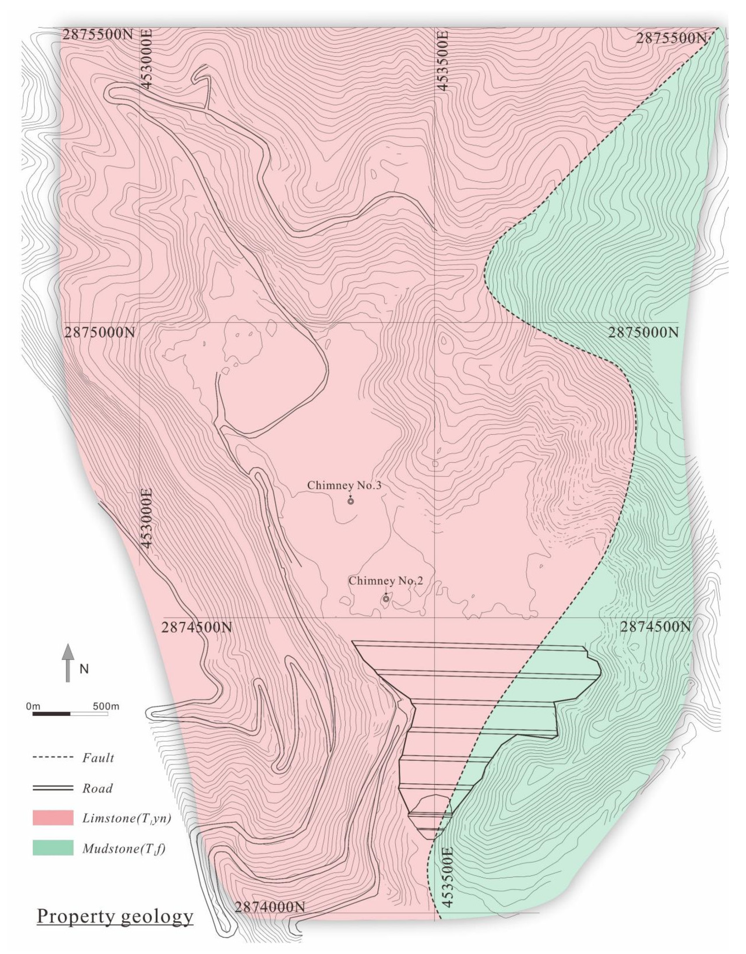
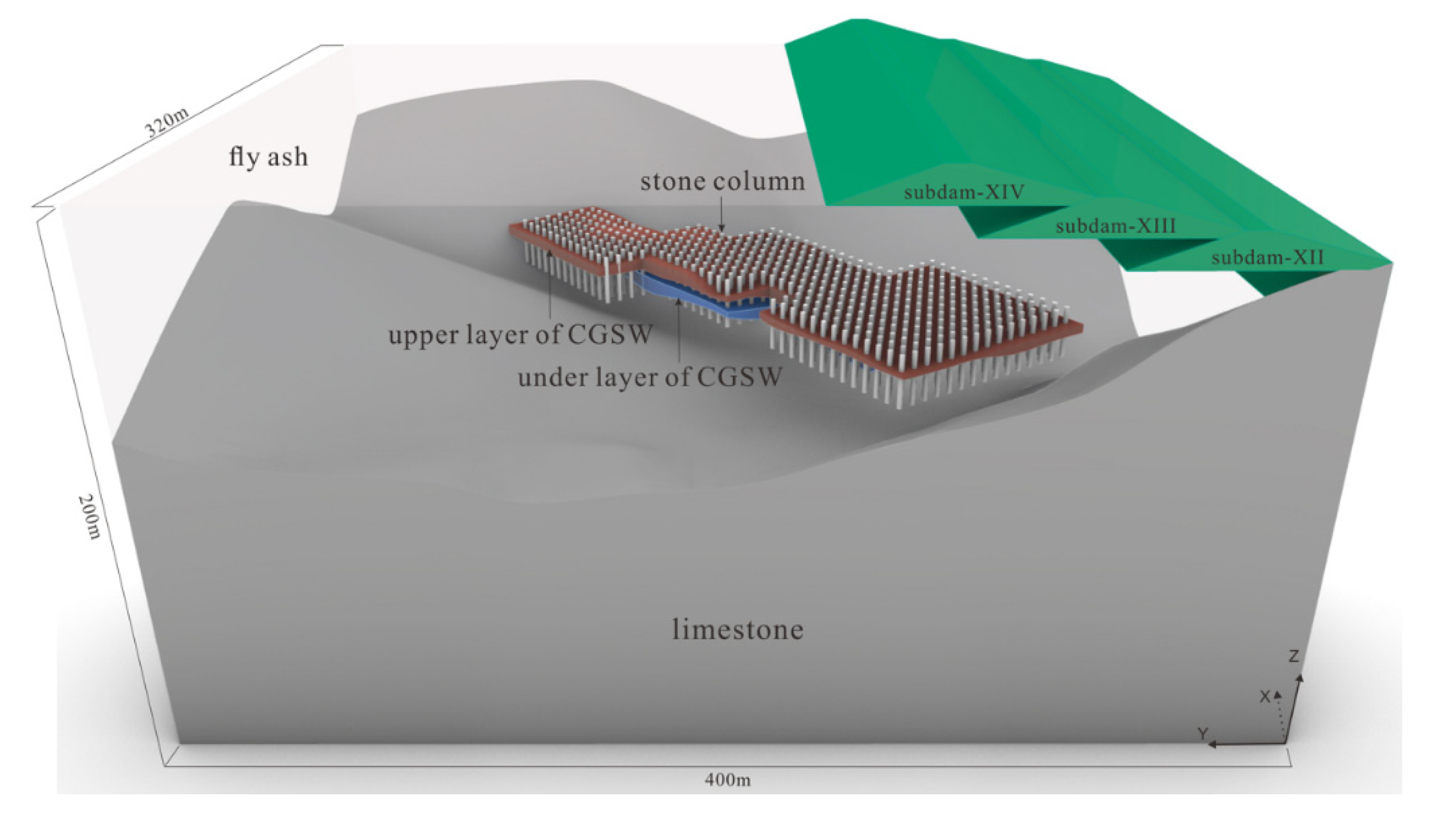
- Bedrock: The bedrock of DAD4 is composed of limestone and mudstone, derived from the Yongningzhen Formation and the Feixianguan Formation, respectively, and both are slightly weathered. The bedrock module was divided into 36,061 zones.
- Fly ash: The fly ash was generated by a power plant 3 km away. It will reach a storage of 26.30 million m3 when DAD4 meets its ultimate capacity. In the Rhino model, this module was divided into 98,110 zones.
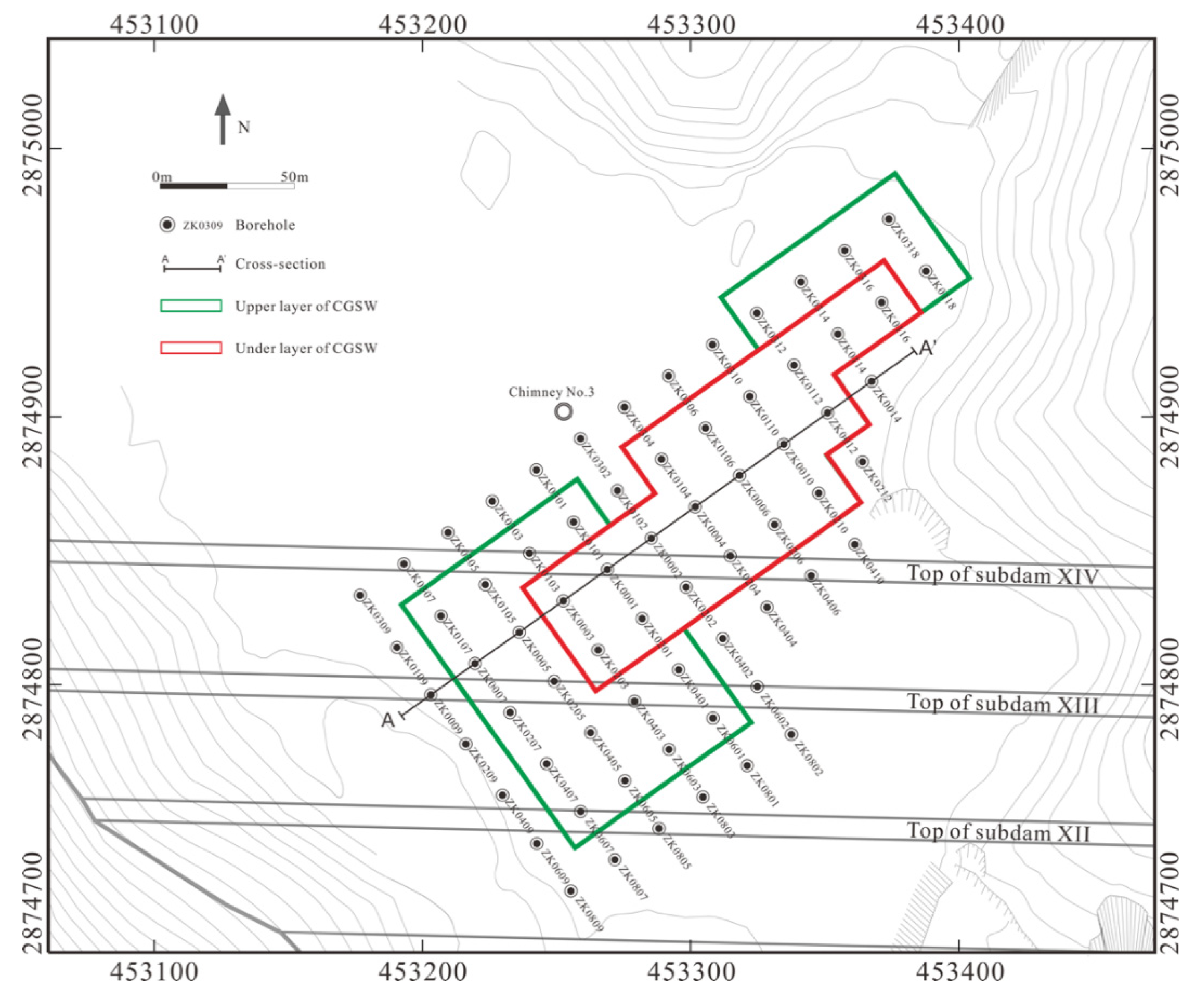
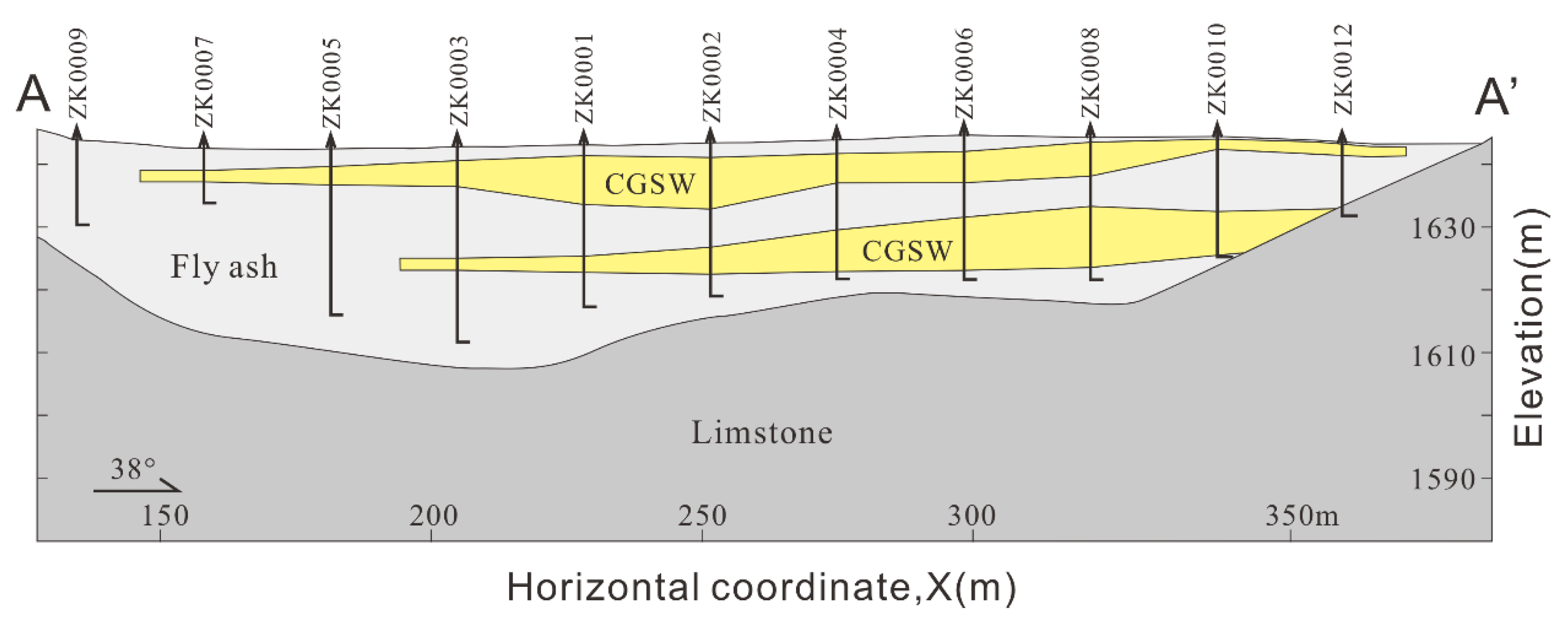
- Coal gangue solid waste: The primary plan for the CGSW was for it to be dumped in DAD4 temporarily in the year 2016 without a further disposal strategy. So, it was buried eventually due to the continuous delivery of fly ash from the power plant. When they understood its possible impact on the stability of subdams and that it might even cause dam failure, the management decided to carry out a geological engineering investigation in September 2021 to confirm the shape and distribution of the buried CGSW. The shape of the buried CGSW was constrained by 42 boreholes. The drilling revealed that the CGSW appeared in two horizontal layers, in parallel with each other and wrapped by fly ash. The mechanical parameters of the fly ash and bedrock were obtained through the laboratory geotechnical test, and the CGSW’s mechanical parameters were from a large-scale triaxial test, which provided a good data basis for numerical simulation. The CGSW module was divided into 2887 zones.
- Primary dam: The primary dam is an essential structure for surface ash disposal facilities constructed by the upstream method; as well as retaining fly ash, it also plays an important role in the drainage system to maintain a low phreatic surface. The primary dam in this case is a rolled rockfill dam made of waste limestone, with a slope ratio of 1:2 on the upstream side and a slope ratio of 1:3 on the downstream side. It rises up to the final height of 28 m, with a length of 121 m in axis; the volume of this starter dam is 97,168 m3. The primary dam module was divided into 31,960 zones.
- Subdam: The subdam is mainly made up of compacted fly ash by vibratory rolling. The rolling test is carried out before construction to provide the best paving thickness, rolling times, optimum moisture content, and optimum compactness. As shown in Figure 4, the dimensions of these subdams are similar, with 70 m in bottom width, 8m in top width, 12 m in height; only the crest length varies from 124 m to 780 m. The subdam is entirely wrapped by an impervious geotextile, and the downstream slope is protected by dry rubble.
- Stone column: The stone column is a mixture of breccia, gravel, and sand, with particle sizes of less than 100 mm. The uniformity coefficient (Cu) of the mixture must be greater than 5, with a curvature coefficient (Cc) between 1 and 3. All the column axes are 15 m to ensure the passing through of the coal gangue burial body. This module mesh must be less than one-fifth of the column diameter.
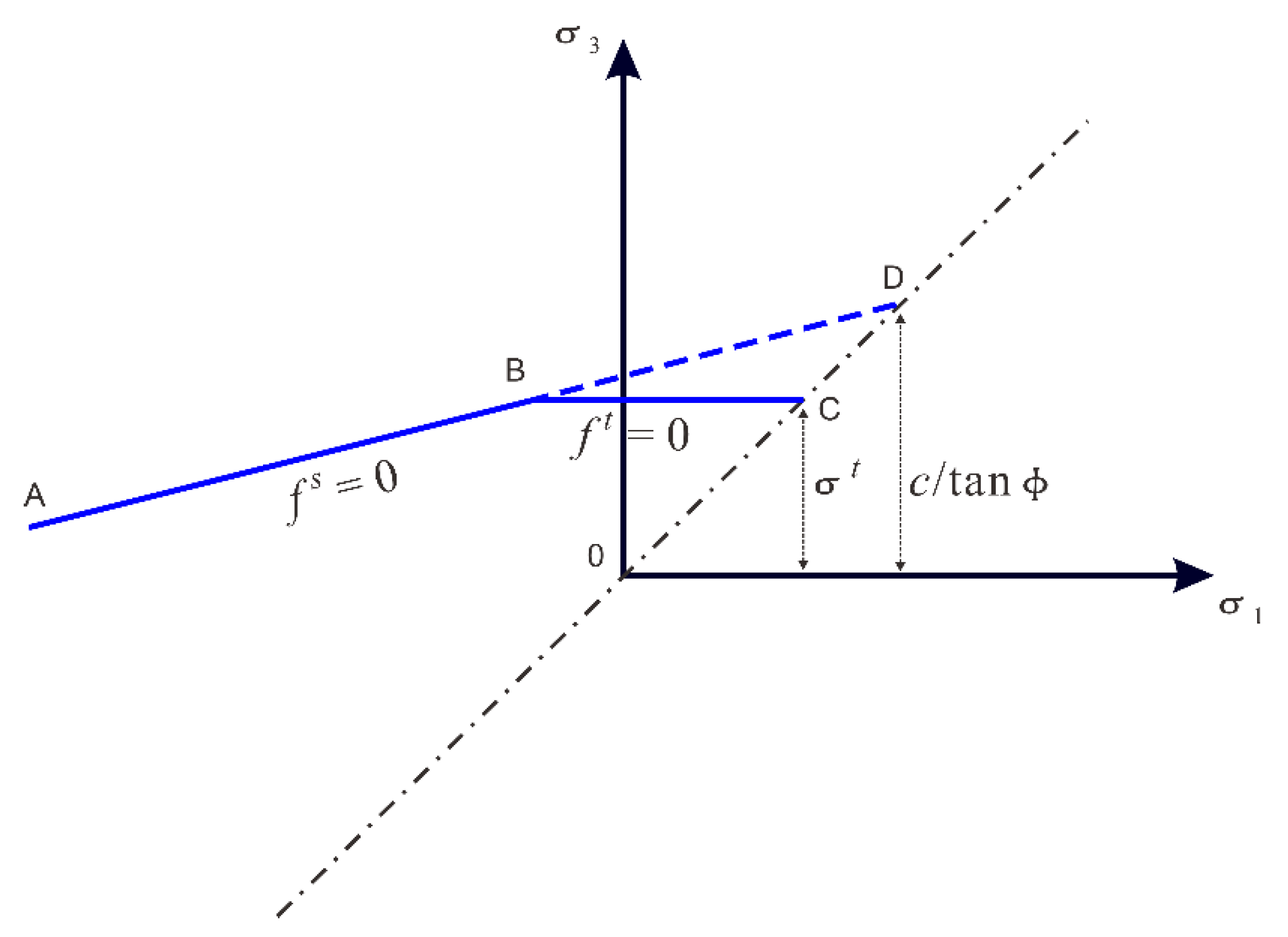
- Dry ash disposal in the valley contains a perfect drainage system and flood-cutting system. Site investigation in 2021 found that the flood-cutting ditch and the drainage system, composed of a chimney, inclined shaft, and horizontal tube, were working well. The drilling operation did not reveal the water table, neither did the seven groundwater observation wells embedded in the early subdams. Under normal circumstances, the drainage system can discharge the infiltration rainwater within ten hours, retaining an unsaturated disposal facility for most of the time. The model was established under normal drainage circumstances; so, the influence of seepage on the uneven settlement was not considered in the simulation. Fast Lagrangian analysis of the continua in three dimensions (Flac3d), developed by Itasca Ltd., was used to provide recommendations for construction design.
3.2. Constitutive Model and Boundary Condition
3.3. Design Basic
3.4. Test Scheme Design
4. Results
4.1. Deformation Analysis
4.2. Subsidence Analysis
4.3. Standard Deviation Analysis
4.4. Analysis Summary
5. Conclusions
- CGSW distribution based on borehole data can help to build a more accurate FLAC3D digital model; this is the basis of the deformation analysis and differential settlement analysis under various subsequent construction schemes.
- If deformation or differential subsidence on top of the CGSW cannot be effectively controlled, it could cause damage to the subdam, such as shear failure or cracking. The subdam stability is dominated by the differential subsidence rather than the absolute magnitude of subsidence. The modeling results indicate that the subdam differential settlement caused by CGSW weathering may threaten the stability of the overlapping subdam-XIV, leading to tension failure in the right and middle abutment.
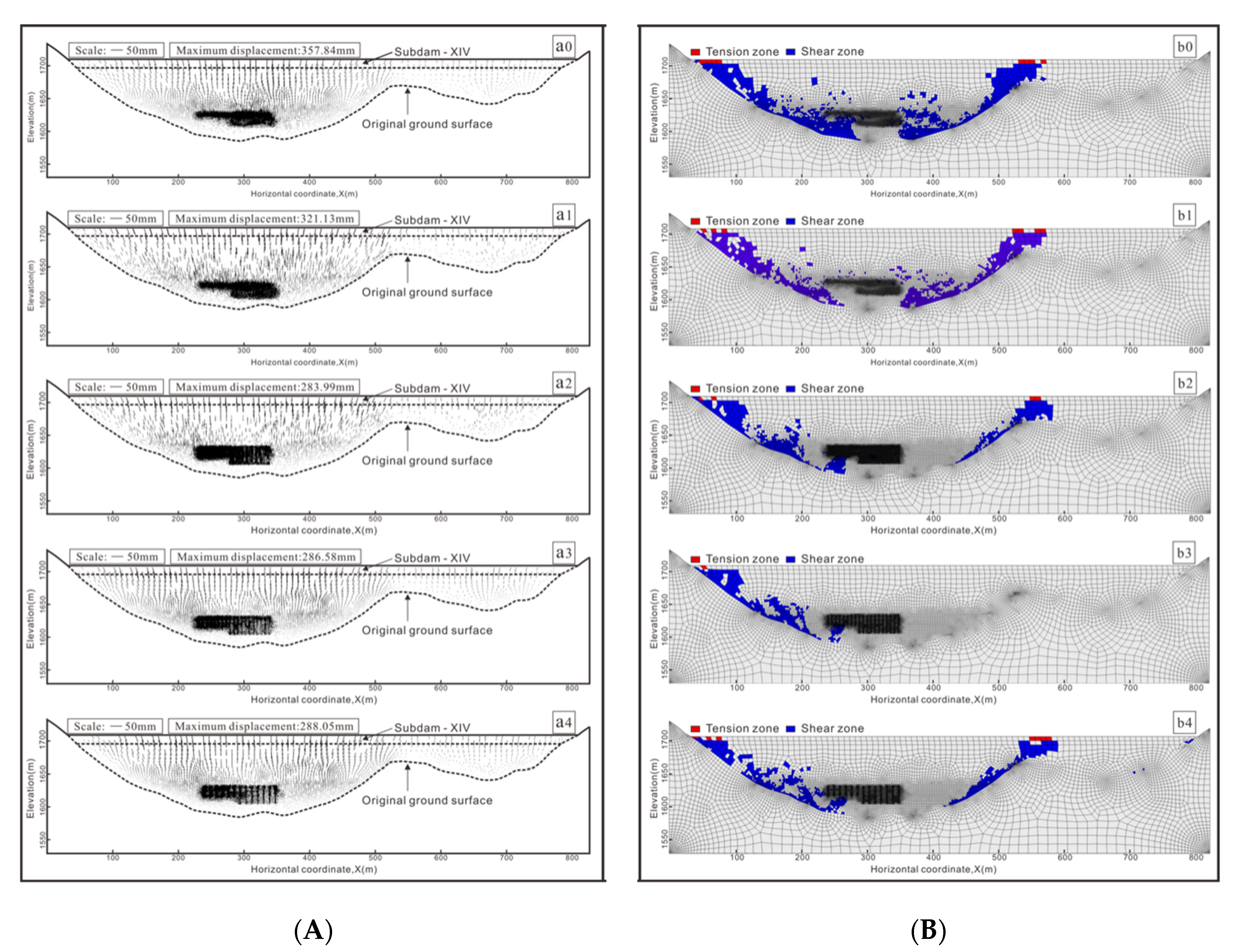
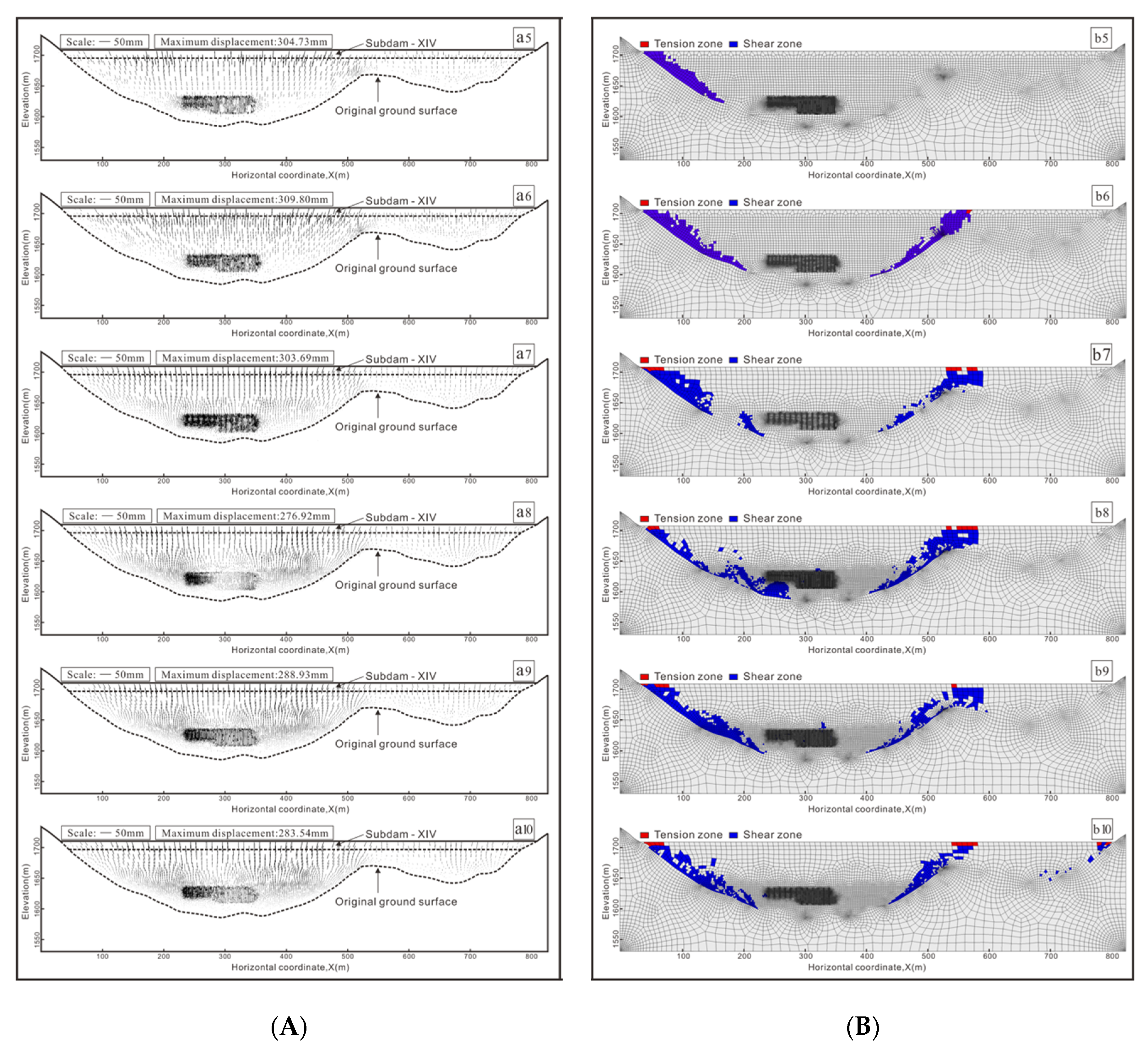
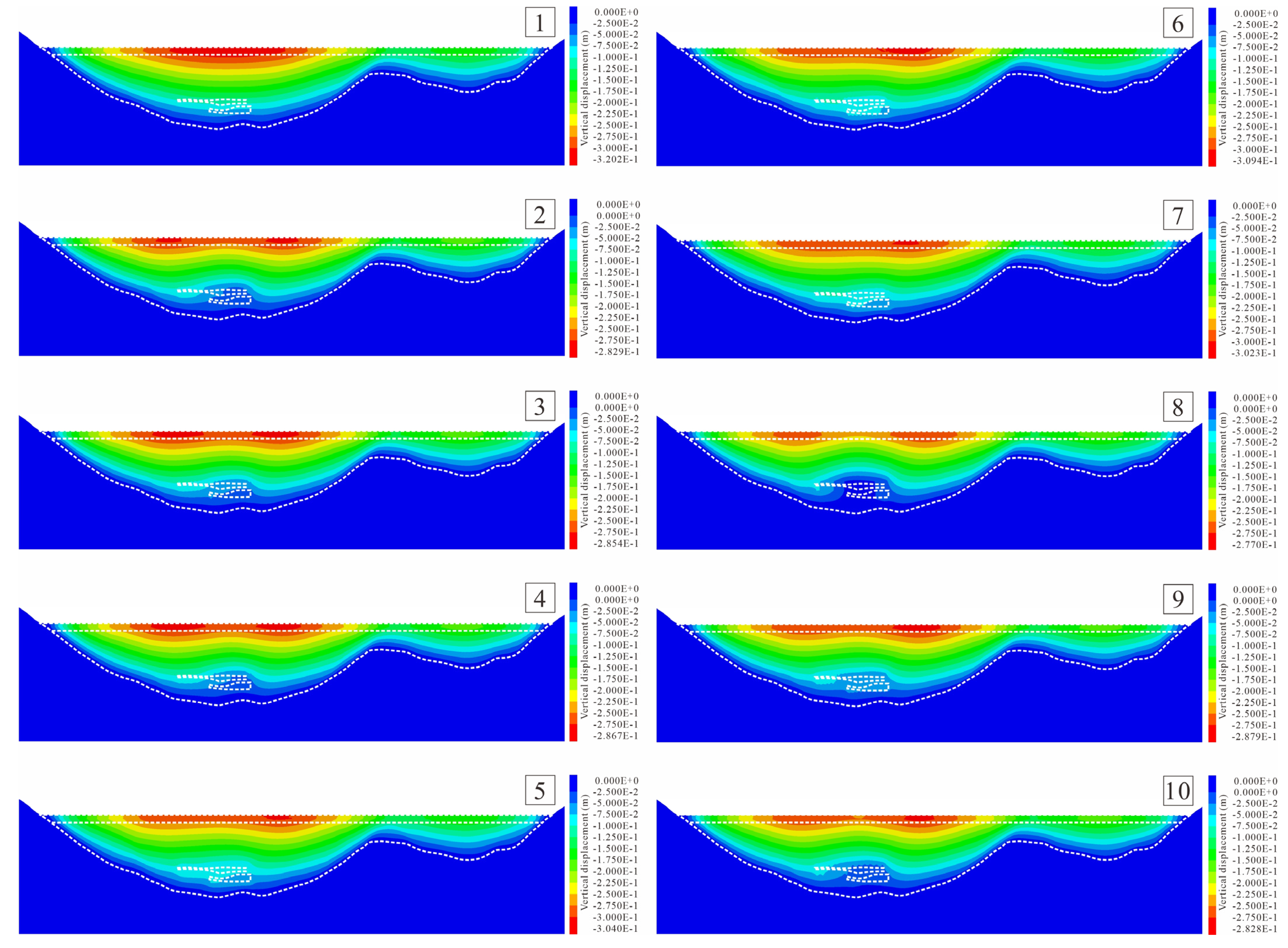
- Both the replacement method and the stone column methods helped to reduce the subdam subsidence value. The displacement method could provide only a 10.615% reduction in the maximum subsidence value; the stone column methods worked better. Scheme 2, 3, 8, and 9 produced reductions of over 20%; scheme 8 provided the best reduction of 22.391%. The deformation analysis showed that scheme 3 and scheme 5 had the best effect in that they both eliminated the tension failure zone in the middle of subdam-XIV. The shear failure zone and tension failure zone in scheme 3 were reduced by 60.51% and 87.75%, respectively, compared to the original condition (scheme 0). Scheme 5 reduced the shear failure zone by 70.75%; meanwhile, it reduced the tension failure zone by 97.83%.
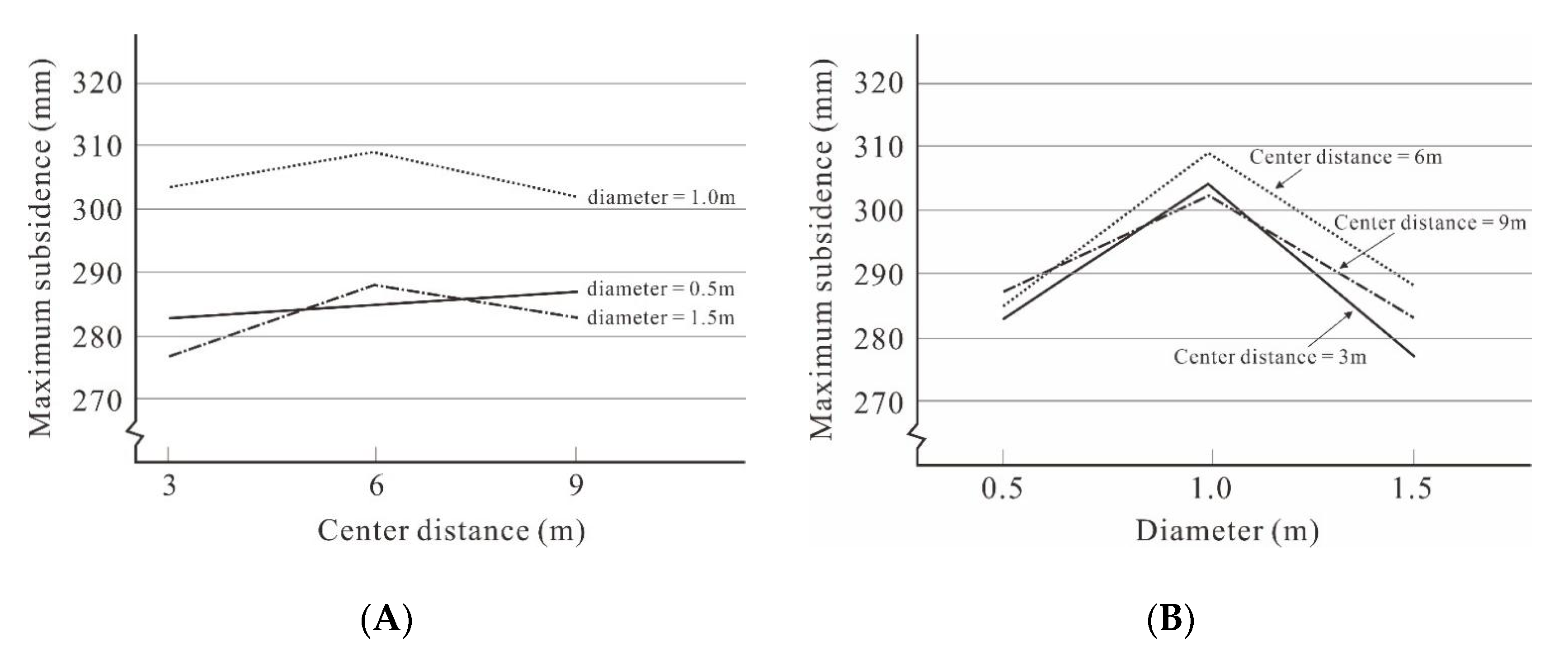
- Generally, it is known that under longitudinal loading conditions three types of deformation or damage, known as “bulge deformation”, “shear damage”, and “block damage”, may occur in the gravel pile. The diameter and spacing of the gravel pile both affect the settlement of the superstructure within the diameter range of 0.5–1.5. Regardless of the pile spacing value, the maximum settlement value of the top surface always exhibits an ascending trend followed by a descending trend. This may be due to the fact that as the diameter (plane replacement rate) increases, the resistance to deformation of the pile–soil system increases; so, the vertical deformation in the pile–soil system will gradually decrease, which leads to a decrease in the maximum settlement value. Conversely, an increase in diameter enlarges the mass of the pile–soil system, leading to an increase in the compressive deformation of the soil layer beneath it, which leads to an increase in the maximum settlement value. This shows that in the deep burial pile–soil system, with the enlargement of the gravel pile diameter, the increase in its lower fly ash compression deformation is first greater than and then less than the decrement of the vertical deformation of the pile–soil system.
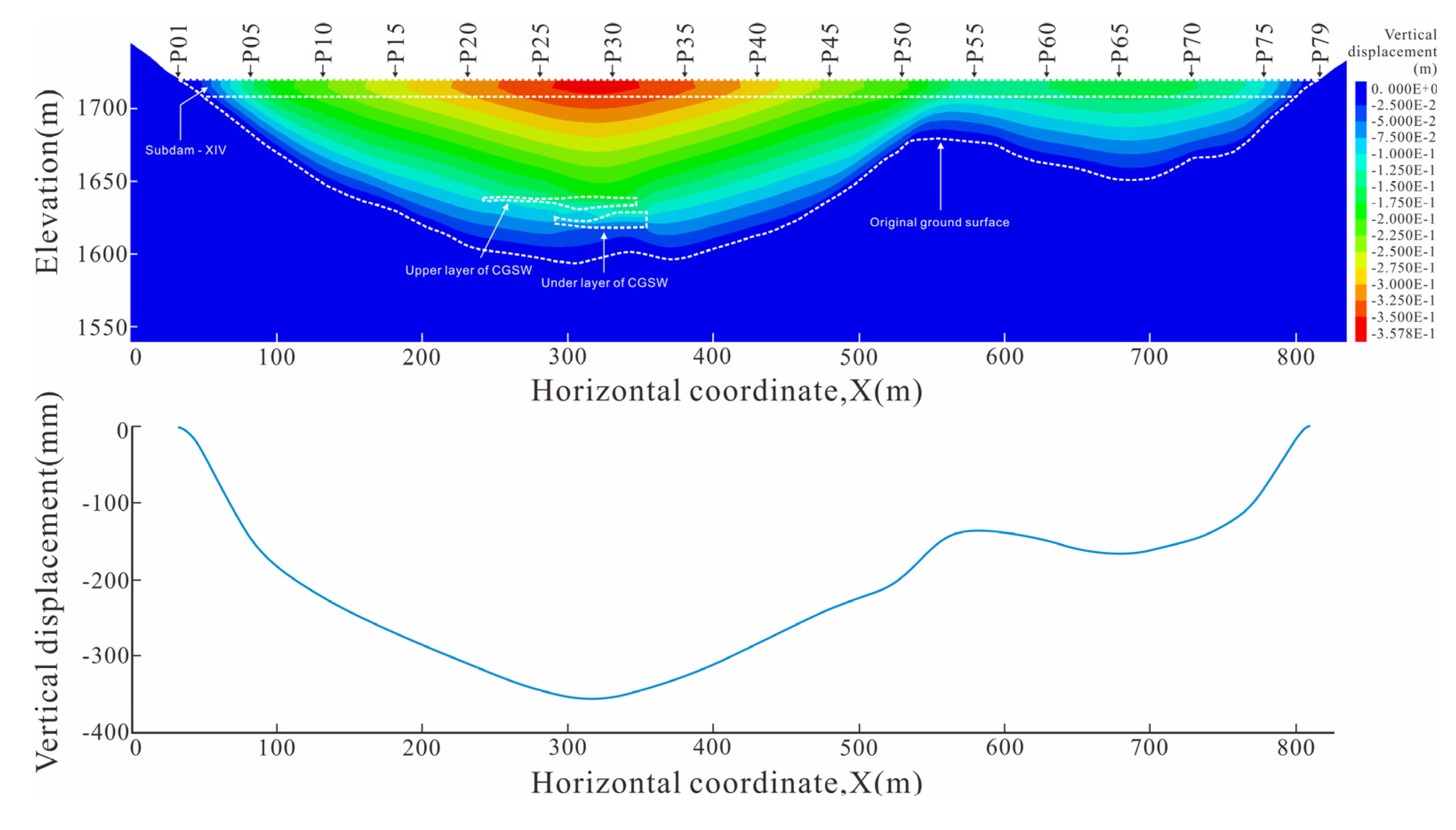
- Subdam-III was constructed in 2016; it has been standing for 7 years since then. Its deformation has stabilized. The settlement observation data of subdam-III are basically consistent with the settlement curve of subdam-III obtained in the simulation, which verifies the reasonableness of the parameters. As this part was not the main focus of this paper, it is not described in detail. The maximum settlement values of various scenarios in the predicted results range from 200 mm to 400 mm, and this also agrees well with the data observed in the operation and the management of other ash sites.
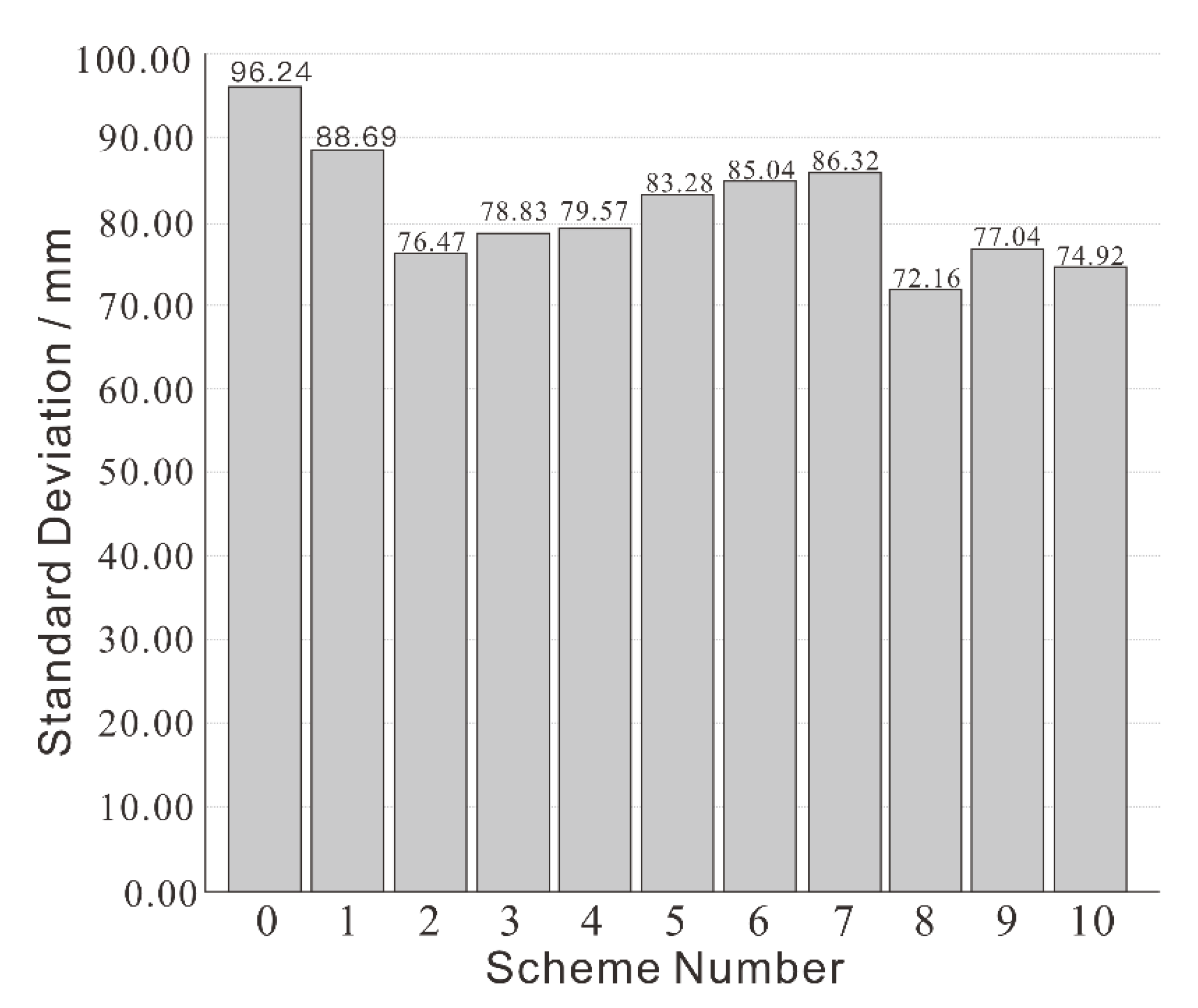
- From the comprehensive perspective of the main deformation analysis and SD analysis, scheme 3 (with a center distance of 6 m and a diameter of 0.5 m) is therefore recommended as the actual construction scheme.
Author Contributions
Funding
Informed Consent Statement
Data Availability Statement
Acknowledgments
Conflicts of Interest
List of Symbols
| Maximum, intermediate, and minimum principal stresses | |
| E | Modulus of elasticity |
| c | Cohesion |
| Tensile strength | |
| Friction angle | |
| Compression yield function | |
| Tensile yield function | |
| α1, α2 | Material constants |
| G | Shear modulus |
| K | Bulk modulus |
| Total volume of tension failure zones in ith scheme | |
| Total volume of shear failure zones in ith scheme | |
| Total volume of the model | |
| Percentage of shear failure zone | |
| Percentage of tension failure zone | |
| Reduction degree of shear failure zone of ith scheme | |
| Reduction degree of tension failure zone of ith scheme |
References
- BP. Statistical Review of World Energy; BP p.l.c.: London, UK, 2021. [Google Scholar]
- CEC. China Power Industry Annual Development Report 2021; China Electricity Council: Beijing, China, 2021. [Google Scholar]
- EPA. Coal Combustion Residual Beneficial Use Evaluation: Fly Ash Concrete and FGD Gypsum Wallboard; US EPA: Washington, DC, USA, 2014. [Google Scholar]
- Gajić, G.; Djurdjević, L.; Kostić, O.; Jarić, S.; Mitrović, M.; Pavlović, P. Ecological Potential of Plants for Phytoremediation and Ecorestoration of Fly Ash Deposits and Mine Wastes. Front. Environ. Sci. 2018, 6, 124. [Google Scholar] [CrossRef]
- Liao, Z.; Xiao, X.; Hu, Y.; Sun, X.; Wang, H.; Zhou, H.; Ma, Y.; Li, J. Toxic effects of coal fly ash on wheat seedlings. Environ. Geochem. Health 2018, 40, 2371–2381. [Google Scholar] [CrossRef] [PubMed]
- Davison, R.L.; Natusch, D.F.S.; Wallace, J.R.; Evans, C.A. Trace elements in fly ash. Dependence of concentration on particle size. Environ. Sci. Technol. 1974, 8, 1107–1113. [Google Scholar] [CrossRef]
- Jones, K.B.; Ruppert, L.F.; Swanson, S.M. Leaching of elements from bottom ash, economizer fly ash, and fly ash from two coal-fired power plants. Int. J. Coal Geol. 2012, 94, 337–348. [Google Scholar] [CrossRef]
- Vick, S.G. Planning, Design and Analysis of Tailings Dams, 2nd ed.; BiTech Publ: Vancouver, BC, Canada, 1984. [Google Scholar]
- UNEP. A Guide to Tailings Dams and Impoundments, Design, Construction, Use and Rehabilitation; UNEP: Paris, France, 1996. [Google Scholar]
- Mittal, M.N. HK Design and Performance of Tailings Dams. Ph.D. Thesis, University of Alberta, Edmonton, AB, Canada, 1974. [Google Scholar] [CrossRef]
- Liu, K.; Ma, T.; Hou, X. Environmental hazards and Comprehensive Utilization of Coal gangue in China. Coal 2013, 239, 59–61. [Google Scholar] [CrossRef]
- Liu, W.; Liu, S.; Tang, C.; Qin, W.; Pan, H.; Zhang, J. Evaluation of surface water quality after mine closure in the coal-mining region of Guizhou, China. Environ. Earth Sci. 2020, 79, 427. [Google Scholar] [CrossRef]
- Gao, H.; Huang, Y.; Li, W.; Li, J.; Ouyang, S.; Song, T.; Lv, F.; Zhai, W.; Ma, K. Explanation of heavy metal pollution in coal mines of china from the perspective of coal gangue geochemical characteristics. Environ. Sci. Pollut. Res. 2021, 28, 65363–65373. [Google Scholar] [CrossRef]
- Sun, Q.; Zhang, J.; Qi, W.; Li, M. Backfill mining alternatives and strategies for mitigating shallow coal mining hazards in the western mining area of China. Q. J. Eng. Geol. Hydrogeol. 2020, 53, 217–226. [Google Scholar] [CrossRef]
- Phenrat, T. Community Citizen Science for Risk Management of a Spontaneously Combusting Coal-Mine Waste Heap in Ban Chaung, Dawei District, Myanmar. GeoHealth 2020, 4, e2020GH000249. [Google Scholar] [CrossRef]
- Li, M.; Zhang, J.; Huang, Y.; Zhou, N. Effects of particle size of crushed gangue backfill materials on surface subsidence and its application under buildings. Environ. Earth Sci. 2017, 76, 603. [Google Scholar] [CrossRef]
- NEA. Code for Design of Dry Ash Disposal Area of Fossil-Fired Power Plant; NEA: Beijing, China, 2014. [Google Scholar]
- Huang, Y.; Li, J.; Ma, D.; Gao, H.; Guo, Y.; Ouyang, S. Triaxial compression behaviour of gangue solid wastes under effects of particle size and confining pressure. Sci. Total. Environ. 2019, 693, 133607. [Google Scholar] [CrossRef] [PubMed]
- Huang, Y.; Li, J.; Teng, Y.; Dong, X.; Wang, X.; Kong, G.; Song, T. Numerical simulation study on macroscopic mechanical behaviors and micro-motion characteristics of gangues under triaxial compression. Powder Technol. 2017, 320, 668–684. [Google Scholar] [CrossRef]
- Wu, J.; Bai, G.-L.; Wang, P.; Liu, Y. Mechanical properties of a new type of block made from shale and coal gangue. Constr. Build. Mater. 2018, 190, 796–804. [Google Scholar] [CrossRef]
- Wu, D.; Luo, F.; Li, M.; Diao, Y.; Guo, Y.; Xu, P. Macroscopic and microscopic study on the compression bearing characteristics and deformation failure mechanism of gangue with different particle sizes. Powder Technol. 2021, 383, 198–211. [Google Scholar] [CrossRef]
- Cai, Y.; Yan, J.; Chen, X.; Xu, L.; Xu, Z.; Yao, J. Weathering characteristics of coal gangue under supergenesis: A case study of Huainan Mining area. J. China Univ. Min. Technol. 2015, 44, 937–943. [Google Scholar] [CrossRef]
- Sainoki, A.; Mitri, H.S.; Chinnasane, D. Characterization of Aseismic Fault-Slip in a Deep Hard Rock Mine Through Numerical Modelling: Case Study. Rock Mech. Rock Eng. 2017, 50, 2709–2729. [Google Scholar] [CrossRef]
- Azam, S.; Li, Q. Tailings Dam Failures: A Review of the Last One Hundred Years. Geotech. News 2010, 28, 50–54. [Google Scholar]
- Lyu, Z.; Chai, J.; Xu, Z.; Qin, Y.; Cao, J. A Comprehensive Review on Reasons for Tailings Dam Failures Based on Case History. Adv. Civ. Eng. 2019, 2019, 4159306. [Google Scholar] [CrossRef]
- U.S. Cold Storage. Tailings Dam Incidents; U.S. Committee on Large Dams: Denver, CO, USA, 1994. [Google Scholar]
- Islam, K.; Murakami, S. Global-scale impact analysis of mine tailings dam failures: 1915–2020. Glob. Environ. Chang. 2021, 70, 102361. [Google Scholar] [CrossRef]
- Gong, Y.; Guo, G. A Data-Intensive FLAC3D Computation Model: Application of Geospatial Big Data to Predict Mining Induced Subsidence. Comput. Model. Eng. Sci. 2019, 119, 395–408. [Google Scholar] [CrossRef]
- Chen, T.; Mitri, H.S. Strategies for surface crown pillar design using numerical modelling—A case study. Int. J. Rock Mech. Min. Sci. 2021, 138, 104599. [Google Scholar] [CrossRef]
- Gao, L.; Chen, Y.; Chen, J.; Yang, X.; Jing, Y. Stability analysis of a tailings pond under seepage based on Flac3d. China Water Transp. 2021, 21, 106–108. [Google Scholar]
- Sun, Y.; Wei, Y.; Cheng, X.; Song, J. Research on the influence of sub-dams heightening to the stress and deformation of ash dam body. J. Hydraul. Eng.-ASCE 2014, 45, 39–44. [Google Scholar] [CrossRef]
- Hughes, J.M.O.; Withers, N.J.; Greenwood, D.A. A field trial of the reinforcing effect of a stone column in soil. Geotechnique 1975, 25, 31–44. [Google Scholar] [CrossRef]
- Khing, K.; Das, B.; Puri, V.; Cook, E.; Yen, S. The bearing-capacity of a strip foundation on geogrid-reinforced sand. Geotext. Geomembr. 1993, 12, 351–361. [Google Scholar] [CrossRef]
- Ambily, A.P.; Gandhi, S.R. Behavior of Stone Columns Based on Experimental and FEM Analysis. J. Geotech. Geoenviron. Eng. 2007, 133, 405–415. [Google Scholar] [CrossRef]
- Zhou, H.; Diao, Y.; Zheng, G.; Han, J.; Jia, R. Failure modes and bearing capacity of strip footings on soft ground reinforced by floating stone columns. Acta Geotech. 2017, 12, 1089–1103. [Google Scholar] [CrossRef]
- Gu, M.X. Three-Dimensional DEM Analysis and Model Tests on Geosynthetic Encased Stone Columns. Ph.D. Thesis, Hunan University, Changsha, China, 2017. [Google Scholar]
- Lan, B. Theoretical Analysis and Engineering Research on the Treatment of Saturated Soft Ground with Crushed Stone Piles. Ph.D. Thesis, Zhongshan University, Zhuhai City, China, 2005. [Google Scholar]
- Guo, B.; Gong, X.N.; Li, Y.J. Analytical solution for consolidation of stone column-reinforced foundations considering radical and vertical flows in columns. Chin. J. Geotech. Eng. 2017, 39, 1485–1492. [Google Scholar] [CrossRef]
- Yang, T.; Li, C. Consolidation analysis of stone column-impervious pile composite ground underneath rigid foundation considering radial and vertical flows within stone columns. Chin. J. Rock Mech. Eng. 2018, 37, 2631–2640. [Google Scholar] [CrossRef]
- Jay, A.; Nagaratnam, S.; Braja, M.D. Soft Clay Engineering and Ground Improvement; CRC Press: Boca Raton, FL, USA, 2021. [Google Scholar]
- Braja, M.D. Principles of Foundation Engineering, 7th ed.; Cengage Learning: Stanford, CA, USA, 1984. [Google Scholar]
- Wang, H.; Han, W.; Zhao, Q. The application of dynamic consolidation replacement method in the high embankment treatment. J. Disaster Prev. Mitig. Eng. 2004, 3, 277–282. [Google Scholar] [CrossRef]
- Fattah, M.Y.; Al-Musawi, H.H.M.; Salman, F.A. Treatment of Collapsibility of Gypseous Soils by Dynamic Compaction. Geotech. Geol. Eng. 2012, 30, 1369–1387. [Google Scholar] [CrossRef]
- Jie, H. Principles and Practices of Ground Improvement; Wiley: Hooken, NJ, USA, 2015. [Google Scholar]
- Ma, B.; Hu, Z.; Li, Z.; Cai, K.; Zhao, M.; He, C.; Chen, Q.; Chen, B.; Huang, X. A Three-Section-Settlement Calculation Method for Composite Foundation Reinforced by Geogrid-Encased Stone Columns. Adv. Civ. Eng. 2021, 2021, 5576713. [Google Scholar] [CrossRef]
- Zhang, Y.; Liu, Y.; Luo, H.; Chen, P.; Li, D.; Liu, E.; Yang, B. A method of calculating the bearing capacity of sand pile composite foundations in a mucky soil layer considering consolidation. Sci. Rep. 2021, 11, 16962. [Google Scholar] [CrossRef] [PubMed]
- Gniel, J.; Bouazza, A. Improvement of soft soils using geogrid encased stone columns. Geotext. Geomembr. 2009, 27, 167–175. [Google Scholar] [CrossRef]
- Pandey, B.; Rajesh, S.; Chandra, S. Time-Dependent Behavior of Embankment Resting on Soft clay Reinforced with Encased Stone Columns. Transp. Geotech. 2022, 36, 100809. [Google Scholar] [CrossRef]
- Elshazly, H.; Elkasabgy, M.; Elleboudy, A. Effect of Inter-Column Spacing on Soil Stresses due to Vibro-Installed Stone Columns: Interesting Findings. Geotech. Geol. Eng. 2008, 26, 225–236. [Google Scholar] [CrossRef]
- Saxena, S.; Roy, L.B. The Effect of Geometric Parameters on the Strength of Stone Columns. Eng. Technol. Appl. Sci. Res. 2022, 12, 9028–9033. [Google Scholar] [CrossRef]
- Bland, J.M.; Altman, D.G. Statistics notes: Measurement error. BMJ 1996, 313, 744. [Google Scholar] [CrossRef]
- Higuchi, K.; Chigira, M.; Lee, D.-H.; Wu, J.-H. Rapid Weathering and Erosion of Mudstone Induced by Saltwater Migration near a Slope Surface. J. Hydrol. Eng. 2014, 20, C6014004. [Google Scholar] [CrossRef]

| Material | Density | Cohesion | Friction | Bulk Modulus | Shear Modulus | Tension |
|---|---|---|---|---|---|---|
| (kg/m3) | (KPa) | (°) | (MPa) | (MPa) | (KPa) | |
| Limestone | 2.69 | 650 | 40 | 11,000 | 11,000 | 6000 |
| Fly ash | 1.41 | 26 | 30 | 30 | 28 | 12 |
| CGSW (saturated) | 2 | 1 | 33 | 8.5 | 6.4 | 0 |
| CGSW (dry) | 1.65 | 26 | 30 | 1200 | 1200 | 0 |
| Stone column | 1.85 | 390 | 42 | 10,000 | 800 | 0 |
| Subdam | 1.53 | 30 | 23 | 32 | 30 | 14 |
| Serial Numbers of Scheme | Parameter of Stone Column | Subsidence Results | Plastic Zone Information | |||||
|---|---|---|---|---|---|---|---|---|
| Center Distances/m | Diameters/m | Maximum Subsidence/mm | Reduction Degree of MS | Percentage of SFZ | Percentage of TFZ | Reduction Degree of SFZ | Reduction Degree of TFZ | |
| 0 | - | - | 358 mm | - | 3.60% | 0.16% | - | - |
| 1 | - | - | 320 mm | 10.615% | 2.68% | 0.13% | 25.63% | 18.93% |
| 2 | 3 m | 0.5 m | 283 mm | 20.950% | 2.80% | 0.08% | 22.24% | 50.62% |
| 3 | 6 m | 0.5 m | 285 mm | 20.391% | 1.42% | 0.02% | 60.51% | 87.75% |
| 4 | 9 m | 0.5 m | 287 mm | 19.832% | 2.79% | 0.12% | 22.41% | 24.72% |
| 5 | 3 m | 1 m | 304 mm | 15.084% | 1.06% | 0.00% | 70.57% | 97.83% |
| 6 | 6 m | 1 m | 309 mm | 13.687% | 2.85% | 0.06% | 20.85% | 60.03% |
| 7 | 9 m | 1 m | 302 mm | 19.642% | 2.62% | 0.15% | 27.15% | 3.89% |
| 8 | 3 m | 1.5 m | 277 mm | 22.626% | 3.01% | 0.13% | 16.40% | 20.06% |
| 9 | 6 m | 1.5 m | 288 mm | 19.553% | 2.61% | 0.08% | 27.41% | 49.55% |
| 10 | 9 m | 1.5 m | 283 mm | 20.950% | 2.11% | 0.21% | 41.27% | 28.96% |
Disclaimer/Publisher’s Note: The statements, opinions and data contained in all publications are solely those of the individual author(s) and contributor(s) and not of MDPI and/or the editor(s). MDPI and/or the editor(s) disclaim responsibility for any injury to people or property resulting from any ideas, methods, instructions or products referred to in the content. |
© 2023 by the authors. Licensee MDPI, Basel, Switzerland. This article is an open access article distributed under the terms and conditions of the Creative Commons Attribution (CC BY) license (https://creativecommons.org/licenses/by/4.0/).
Share and Cite
Wang, H.; Wu, Y.; Tian, Y.; Li, X.; Yang, Z.; He, L. Numerical Simulation of Subdam Settlement in Ash Disposal Based on CGSW Optimization. Appl. Sci. 2023, 13, 8370. https://doi.org/10.3390/app13148370
Wang H, Wu Y, Tian Y, Li X, Yang Z, He L. Numerical Simulation of Subdam Settlement in Ash Disposal Based on CGSW Optimization. Applied Sciences. 2023; 13(14):8370. https://doi.org/10.3390/app13148370
Chicago/Turabian StyleWang, Hao, Yong Wu, Yun Tian, Xuefeng Li, Zongyao Yang, and Lindong He. 2023. "Numerical Simulation of Subdam Settlement in Ash Disposal Based on CGSW Optimization" Applied Sciences 13, no. 14: 8370. https://doi.org/10.3390/app13148370
APA StyleWang, H., Wu, Y., Tian, Y., Li, X., Yang, Z., & He, L. (2023). Numerical Simulation of Subdam Settlement in Ash Disposal Based on CGSW Optimization. Applied Sciences, 13(14), 8370. https://doi.org/10.3390/app13148370


