Abstract
In the machining process for herringbone gears manufactured by numerical control gear-shaping machines, out-of-tolerance problems of symmetry error generally exist. This paper proposed a high-precision control of spatial symmetry error in the one-time forming machining for herringbone gear. To improve the machining symmetry accuracy and quality of herringbone gear, a mathematical model of measurement, evaluation and compensation for spatial symmetry error was established based on the least square method. Meanwhile, a new shaping machining method based on spatial symmetry error detection and compensation was proposed. The test results indicated that the proposed method can maintain symmetry within 0.02 mm. This study provided a novel spatial symmetry error detection and compensation machining method for herringbone gear that has advantages compared to traditional methods in terms of machining accuracy, efficiency, and continuous machining type.
1. Introduction
Modern gear transmissions are being developed for higher speeds and heavier loads, which pose higher requirements for the static accuracy and dynamic performance of gears [1,2,3]. As an important transmission component, herringbone gears are widely used in high-speed, heavy-duty, and high-power transmission systems such as aviation and vessel transmission equipment and other mechanical transmission areas because of their advantages in transmission stability and strong bearing capacity [4,5,6]. Therefore, high accuracy in the manufacture of herringbone gears is increasingly required [7,8,9,10]. Even more, the spatial symmetry of herringbone gears directly affects transmission errors, transmission efficiency and service life, which are significant for transmission systems [11,12]. At present, tooth profile and tooth direction modifications are research priorities that can improve the stability of and reduce vibrations in gear transmission systems [13,14,15,16,17]. Thus far, manufacturers have lacked a high-precision and high-efficiency control processing method for on-line detection and compensation of spatial symmetry errors in herringbone gears [18].
In recent years, many scholars at home and abroad have conducted numerous related studies on herringbone gear machining methods and the principles of processing error influence on transmission characteristics. Meanwhile, advanced machining methods based on online detection and compensation machining technology have great reference value. Okafor et al. [19] proposed the development of kinematic error models accounting for geometric and thermal errors in the vertical machining center, and used the error model to calculate and predict the resultant error vector at the tool–workpiece interface for error compensation. Kramer et al. [20] developed a feature-based inspection and control system to realize completion of whole machining and detection and compensation processes on machine tools. Kang et al. [14] developed a new double-helical test setup for operating a double-helical gear pair under realistic torque and speed ranges. Liu et al. [21] proposed a dynamic model that includes friction and tooth profile error excitation for herringbone gears and used the proposed model in the dynamic analysis of the variable speed process of a herringbone gear transmission system. Guiassa et al. [22] proposed a cutting compliance coefficient model to estimate corrections for the tool path at the finish cut based on a finite number of measured errors at discrete locations for previous cuts, and presented an integrated methodology for compensation errors detected with an on-machine touch probe. Mao et al. [23] studied the influence mechanism of manufacturing error and assembly error on the load sharing characteristics of a transmission system. Zhou et al. [24] investigated the effects of centering error and angular misalignment on crack initiation life in herringbone gears. Mallipeddi et al. [25] compared gear surface characteristics generated by grinding, honing and superfinishing of case-hardened steel. Gao et al. [26] proposed an error compensation machining method that improves complex surface components based on analyzing the error factors influencing the inspection accuracy of on-machine detection systems. Yang et al. [27] established a mathematical model of comprehensive error compensation for complex thin-wall parts and performed machining tests of error compensation. In a word, the above research findings developed on-line detection and compensation machining technology to some degree. However, they had some limitations that could not be effectively applied to real-time spatial symmetry error detection and compensation machining processes for herringbone gears. Further, investigations reporting on the measurement and evaluation of spatial symmetry errors in herringbone gears and machining methods for their compensation have not been reported so far.
In this study, an accurate shaping machining method based on spatial symmetry error detection and compensation (SSEDC) for herringbone gears is proposed. A mathematical model of spatial symmetry error was established based on spatial projection and the least square method (LSM). On the basis of analyzing symmetry out of tolerance as well as methods of measurement and evaluation of spatial symmetry error, a new machining method based on SSEDC is proposed for the first time. The test results indicate that the machining method based on SSEDC can consistently keep symmetry within 0.02 mm.
2. Measurement, Evaluation and Compensation Model for Spatial Symmetry Errors
2.1. Measurement and Evaluation Model for Spatial Symmetry Errors
Spatial symmetry errors in herringbone gears come from deviations in the starting machining position between the upper and lower teeth. If the involute curve of a herringbone gear is enlarged indefinitely, the shape of the herringbone gear will be similar to an oblique gear rack, and the actual spatial symmetry error shown in Figure 1 will be the offset error of the center position for the upper and lower teeth. Thus, the spatial symmetry error of the herringbone gear shown in Figure 2 can be assumed to be a circular angle error. Therefore, in order to identify a herringbone gear’s spatial symmetry error, it is important to calculate and acquire the circular angle error of the upper and lower teeth through measurement and calculation using a mathematic model.
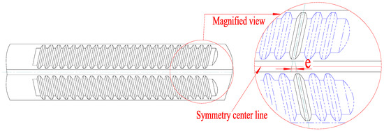
Figure 1.
Symmetry error of oblique gear rack.
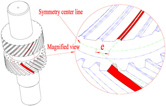
Figure 2.
Spatial symmetry error of herringbone gear.
The phase error at the symmetrical position of the upper and lower helical teeth of the herringbone gear is detected by the probe. After many tests, the measurement of the spatial symmetry error value of the herringbone gear is completed.
To realize the detection and compensation of a herringbone gear’s spatial symmetry error, the symmetry plane of the left and right revolving gear is defined as the symmetry center plane O. As shown in Figure 3, the position measurements of planes A, B, C and D are completed with the touch probe, and the random points can be written as , , and . Further, the position coordinates of midpoints connected with corresponding points of the same height can be expressed as , , and , . Using a plane fitting method, the fitting symmetry plates E and F based on the position coordinates of the midpoints are calculated respectively. Using a spatial projection method, the projection line equations of plane E and F projecting on the plane O are calculated, respectively. As shown in Figure 4, we ensure the two projection lines are parallel through approximate processing of the projection line equations, and then calculate the linear distance of the two projection lines. In fact, the spatial symmetry error is usually relatively small in the machining process. Thus, the deflection chord length, that is, spatial symmetry error, is infinitely equivalent to the linear distance .
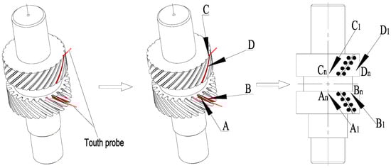
Figure 3.
Schematic diagram of detected spatial symmetry error.
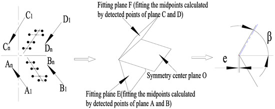
Figure 4.
Schematic diagram of evaluated spatial symmetry error.
The sets of position coordinate midpoints connected with plane A and B corresponding to points of the same height can be written as follows:
In the same way, the sets of position coordinate midpoints connected with plane C and D corresponding to points of the same height can be written as follows:
The fitting symmetry plate E and F can be calculated based on spatial analytic geometry and the calculated midpoint sets. The equations of plane E and F can be formulated as follows:
Utilizing LSM to calculate the fitting symmetry planes, the results can be calculated as follows:
The fitting planes E and F intersect with symmetry center plane O in the spatial, and the intersection line equations can be calculated based on spatial analytic geometry. Further, the two intersection lines should not be completely parallel in theory, but approximate processing should be performed to ensure they are parallel in practice. Thus, the herringbone gear’s spatial symmetry error is the X-axis coordinate distance in XOY coordinate system for the two intersection lines.
2.2. Compensation Model of Spatial Symmetry Error
On the basis of the proposed measurement and evaluation model for a herringbone gear’ spatial symmetry error, the spatial symmetry error is translated into displacement deviation . In fact, the herringbone gear’s spatial symmetry error cannot be compensated through rotating the gear or controlling the worktable’s rotating axis. To achieve compensation of the spatial symmetry error, the controlled target is translated into the gear shaping cutter according to the generating machining method. Thus, the movements involved in the gear shaping cutter need to be analyzed.
As shown in Figure 5, the movements of the gear shaping cutter mainly include the principal cutting movement (P), circular cutting motion of numerical control (NC) axis C2 (C2), cutter back-off motion (B) and movement of oblique knife (S). Apparently, the angle error compensation of the tangential direction cannot be realized through controlling movement P; moreover, the simplex control of movement C2 can make tangential displacement in the gear machining process, and the motion B only involves the axial direction because the spatial symmetry error is translated into displacement deviation at the X-axis coordinate. Therefore, the method of controlling movement S is proposed to compensate for the displacement deviation , and this method is viable to compensate for the tangential displacement through approximation in theory. The compensation model of the herringbone gear’s spatial symmetry error is shown in Figure 6. Finally, the whole closed loop system of measurement and compensation machining on the herringbone gear’s spatial symmetry error is realized.
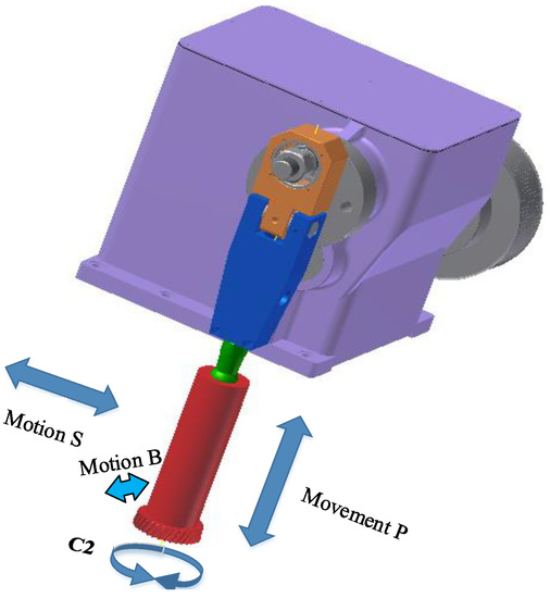
Figure 5.
Schematic diagram of movements involved in gear shaping cutter.
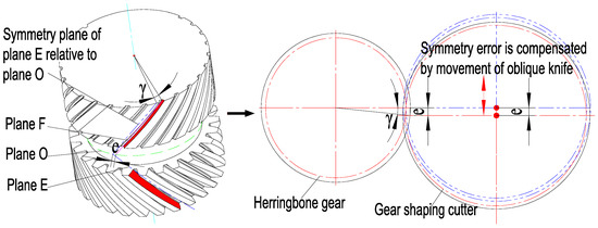
Figure 6.
Compensation model of spatial symmetry error.
On the basis of the proposed compensation model for the herringbone gear’s spatial symmetry error, the spatial symmetry error is translated into displacement deviation and can be written as follows. Further, the movement of the oblique knife is adjusted, and then the gear shaping cutter should be adjusted to confirm the mesh after compensating for the spatial symmetry error. The angle can be written as follows:
where , , , and are the herringbone gear’s module, tooth number, pitch diameter and angle error, respectively, where , , and are the gear shaping cutter’s module, tooth number, pitch diameter and angle error, respectively.
Therefore, by setting up the measurement and evaluation and compensation model of the herringbone gear’s spatial symmetry error, the machining process for on-line detection and compensation of the herringbone gear’s spatial symmetry error can be intuitively displayed, providing theoretical support for instance machining.
3. Herringbone Gear Machining Method Based on SSEDC
3.1. Machining Flow
Herringbone gears are composed of left and right screw surfaces. The left and right screw surface intersection can constitute multiple planes. The plane symmetry to the gear face is usually called the herringbone gear center plane. Because of restriction of the reducer structure and normal meshing transmission requirement, the herringbone gear must set the position when assembling, and positioning error of he plane must be controlled in the allowed range of the assembly adjustment amount, which means that the symmetry of the left- and right-hand gears must be well-maintained, and the position error should be generally controlled within 0.05 mm.
According to the above analysis, a machining flow chart for a herringbone gear based on SSEDC is proposed, combined with the machining process for the gear, as shown in Figure 7. The key point in the machining process is to achieve detection through a measuring device and control it to detect the phase symmetry of the upper right-hand and lower left-hand groove center of the herringbone gear. Then, on the basis of the proposed method, the spatial symmetry error can be calculated and compensated in the machining process.
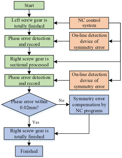
Figure 7.
Machining flow chart for herringbone gear based on SSEDC.
Combined with the actual herringbone gear machining process, the basic machining flow chart for the herringbone gear based on SSEDC is shown in Figure 8.
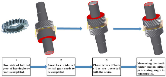
Figure 8.
Flow chart of actual herringbone gear machining process based on SSEDC.
3.2. Design of Fixture and On-Line Device for Spatial Symmetry Error Measurement
To clamp the herringbone gear and ensure the accuracy and efficiency of herringbone gear machining, a general fixture for hydraulic drive self-clamping is designed; it is composed of a pull rod, core clamper, spring, collect chuck, positioning sleeve, fixture body, etc., as shown in Figure 9. When the hydraulic cylinder drives the pull rod downward, the pull rod drives the collect chuck to clamp the shaft diameter of the herringbone gear and ensures that the positioning surface of the herringbone gear is attached to the positioning plane of the fixture, in order to facilitate automatic clamping of the herringbone gear. Table 1 lists the basic parameters of the herringbone gear.
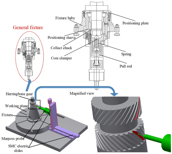
Figure 9.
Schematic diagram of designed fixture and OMFSDD.

Table 1.
Basic parameters of herringbone gear.
Meanwhile, an on-line spatial symmetry error measuring device controlled by the program of an NC system is designed to measure points on surfaces of the machining teeth. The symmetry center plane can be calculated based on the proposed method. As shown in Figure 9, the on-line measuring device is composed of a Marposs T25 probe and two electric slides [28]. The horizontal and vertical electric slides allow multi-degree freedom of movement of the Marposs probe. On that basis, measurements of gears of different heights and sizes can be realized.
The detection principle and process of the device are as follows. The NC program controls the electric slides to turn the measuring head into the left-handed slot of the gear (as shown in Figure 9). After measuring the tooth centers of the up and down gears, an initial processing angle will be compensated and corrected according to the center deviation value to meet the requirements of symmetry.
4. Case Study
4.1. Measurement and Compensation of Spatial Symmetry Error
To improve machining efficiency in the detection and compensation process, actually, the quantity of detected points can be reduced to two points for each tooth surface. Because the gear shaping cutter has high accuracy and the processed helix angle is constant, the three-dimensional spatial symmetry error can be reduced to a one-dimensional displacement deviation. Meanwhile, in order to compare and validate the detected data, it is necessary to detect two points for each tooth surface. Hence, in the actual machining process, the spatial symmetry error amount is calculated based on the data for a total of eight detected points on four tooth surfaces.
As shown in Figure 10, the positioning end plane is defined as the reference plane, and a total of four points whose heights are, respectively, and are detected by the on-line measuring device. As shown in Figure 11, corresponding to the heights of , and , points and , and , and , and are respectively detected. Based on the calculation and compensation methods in the actual machining process, the X-axis coordinates are chosen to calculate the spatial symmetry error. Therefore, the displacement error and can be written as follows:
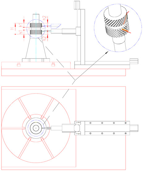
Figure 10.
Schematic diagram of requirement for corresponding detected points.
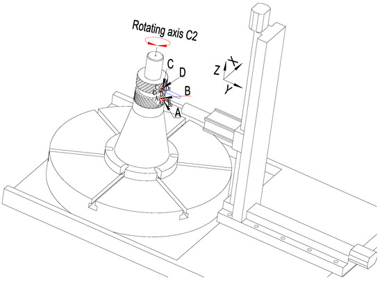
Figure 11.
Schematic diagram of actual detection process based on SSEDC.
Then, through comparing the calculated error, the spatial symmetry error in the actual machining process can be written as follows:
The actual detection and compensation process is shown in Figure 12. The diagram of the NC shaping machine drive system is shown in Figure 13.
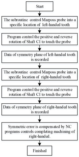
Figure 12.
Flow chart of the actual detection and compensation process.
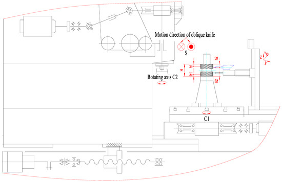
Figure 13.
Diagram of the shaping machine drive system and on-line symmetry error detection device.
4.2. Machining and Accuracy
Shown in Figure 14 is a diagram of the herringbone gear machining process for a special gear-shaping machine. Firstly, the NC program should be developed according to the flow chart of the actual detection and compensation process, including the right- and left-hand gear machining programs and symmetry error detection programs. Secondly, the preparation work should be performed before the machining of herringbone gears, including gear clamping, positioning, alignment, program debugging, etc. Then, the numerical control program controls the gear shaper to complete the processing of the right-handed gear and controls the Marposs probe to locate and determine the symmetrical position of the calibration slot.
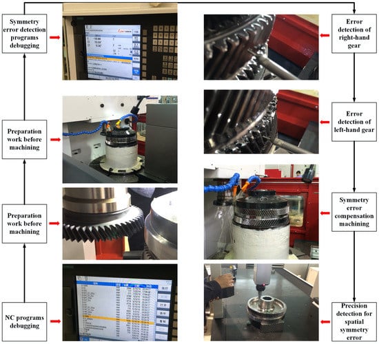
Figure 14.
Diagram of machining process for herringbone gear with a special-gear shaping machine.
After that, the herringbone gear is turned over and clamped, and the above steps are repeated to complete the processing of the left-handed gear (without cutting to the tooth depth). The numerical control program controls the Marposs probe to complete the measurement of the left-handed tooth space position corresponding to the position of the right-handed gear calibration slot. Finally, the calculation of the spatial symmetry error is completed, and the phase compensation processing is carried out. Based on the designed special fixture, specific NC machining programs are developed and debugged, and three types of herringbone gears are manufactured on this special NC gear-shaping machine.
The machining process for the measurement and compensation of herringbone gear spatial symmetry error is shown in Figure 14, including NC program debugging, preparation work before machining, without shaping to the tooth depth, symmetry error detection program debugging, detection of right- and left-hand gear errors, symmetry error compensation machining and precision detection of spatial symmetry error.
Based on the proposed machining method, the results of the machining experiments indicated that the symmetry can be reliably controlled within 0.015 mm. As shown in Figure 15a, the machining instances for herringbone gear were extended to other sizes. As shown in Figure 15b, the machining accuracy of symmetry detected by the coordinate measuring machine can be controlled within 0.02 mm with SSEDC. Comparing the traditional and novel machining methods, the contrasting results are shown in Table 2.
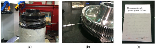
Figure 15.
Diagram of herringbone gear machining and detection with SSEDC. (a) Machining process. (b) Accuracy measurement. (c) Measurement results.
Table 2.
Comparison of herringbone gear machining accuracy and efficiency with different machining methods.
5. Conclusions
We proposed a novel shaping and machining method based on SSEDC for herringbone gears that can realize high-precision control of spatial symmetry error in a one-time forming and machining process. First, a herringbone gear spatial symmetry error measurement and evaluation model was initially established based on spatial projection and LSM. Then, a herringbone gear spatial symmetry error compensation model was further established. Finally, an online detection and compensation machining method for herringbone gear spatial symmetry errors was first created.
Based on the established spatial symmetry error measurement, evolution and compensation mathematical model, a general fixture and an on-line spatial symmetry error detection device were designed for automatic detection and control of spatial symmetry errors. Additionally, to improve machining efficiency in the detection and compensation process, three-dimensional spatial symmetry errors were reasonably reduced to one-dimensional displacement deviations. Further, the specific processes of practical engineering were proposed and applied.
Numerous machining cases were performed based on the proposed SSEDC method and extended to other, different sizes of herringbone gears. The machining cases indicated that the proposed machining method could consistently maintain symmetry within 0.02 mm. Thus, the proposed SSEDC method for solving the out-of-tolerance problem of spatial symmetry error shows reliability and stability.
Author Contributions
Conceptualization, Z.L.; Methodology, H.Z.; Validation, H.Z.; Investigation, Z.L.; Writing—original draft, H.Z.; Writing—review and editing, Z.L.; Project administration, H.Z. All authors have read and agreed to the published version of the manuscript.
Funding
This research work was supported by the Youth Fund project of the National Natural Science Foundation of China (No. 52109157).
Institutional Review Board Statement
Not applicable.
Informed Consent Statement
Not applicable.
Data Availability Statement
Data sharing not applicable.
Acknowledgments
The authors thank the reviewers and editors for useful comments and suggestions that helped to improve the paper.
Conflicts of Interest
The authors declare no conflict of interest.
References
- Wang, Y.Z.; Lan, Z.; Hou, L.W.; Chu, X.M.; Yin, Y.Y. An efficient honing method for face gear with tooth profile modification. Int. J. Adv. Manuf. Technol. 2017, 90, 1155–1163. [Google Scholar] [CrossRef]
- Su, J.Z.; Li, X.D.; Yin, X.M.; Jia, H.T.; Guo, F. Design and form grinding principle of linear triangular end relief for double helical gears. J. Mech. Eng. 2023, 59, 121–129. [Google Scholar]
- Jia, J.Y.; Shen, Y.B.; Cao, J.F. Influence of symmetry deviation of herringbone gears on the system vibration characteristics. J. Xi’an Technol. Univ. 2022, 42, 230–237. [Google Scholar]
- Dong, J.C.; Wang, S.M.; Lin, H.; Wang, Y. Dynamic modeling of double-helical gear with Timoshenko beam theory and experiment verification. Adv. Mech. Eng. 2016, 8, 1687814016647230. [Google Scholar] [CrossRef]
- Ren, F.; Qin, D.T.; Lim, T.C.; Lyu, S.K. Study on dynamic characteristics and load sharing of a herringbone planetary gear with manufacturing errors. Int. J. Precis. Eng. Manuf. 2014, 15, 1925–1934. [Google Scholar] [CrossRef]
- Wang, F.Z.; Fang, D.; Li, S.J.; Li, J.H.; Jiang, J.K. Analysis optimization and experimental verification of herringbone gear transmission system. J. Mech. Eng. 2015, 51, 34–42. [Google Scholar] [CrossRef]
- Li, Z.B.; Wang, S.M. Study on nonlinear dynamic characteristics of power six-branch herringbone gear transmission system with 3D modification. Proc. Inst. Mech. Eng. 2023, 237, 193–219. [Google Scholar] [CrossRef]
- Wei, K.; Lu, F.X.; Bao, H.Y.; Zhu, R.P. Mechanism and reduction of windage power losses for high speed herringbone gear. Proc. Inst. Mech. Eng. Part C J. Mech. Eng. Sci. 2023, 237, 2014–2029. [Google Scholar] [CrossRef]
- Ma, Y.G.; Zhang, X.J.; Fang, Z.D.; Yin, X.M.; Xu, Y.Q. A new analysis technology of the vibration characteristic of the gearbox case of herringbone gear reducer. Appl. Acoust. 2023, 205, 109289. [Google Scholar]
- Wang, L.; Du, Z.K.; Wang, Y.; Zheng, Z.Z.; Chen, G.D. Temperature measurement and error analysis of the transverse plane of oil-jet-lubrication herringbone gear with infrared pyrometers. Rev. Sci. Instrum. 2023, 94, 024902. [Google Scholar] [CrossRef]
- Wei, J.; Gao, P.; Hu, X.L.; Sun, W.; Zeng, J. Effects of dynamic transmission errors and vibration stability in helical gears. J. Mech. Sci. Technol. 2014, 28, 2253–2262. [Google Scholar] [CrossRef]
- Zhai, H.F.; Zhu, C.C.; Song, C.S.; Liu, H.J.; Li, G.F.; Ma, F. Dynamic modeling and analysis for transmission system of high-power wind turbine gearbox. J. Mech. Sci. Technol. 2015, 29, 4073–4082. [Google Scholar] [CrossRef]
- Wang, Y.; Yang, W.; Tang, X.; Lin, X.; He, Z. Power Flow and Efficiency Analysis of High-Speed Heavy Load Herringbone Planetary Transmission Using a Hypergraph-Based Method. Appl. Sci. 2020, 10, 5849. [Google Scholar] [CrossRef]
- Kang, M.R.; Kahraman, A. An experimental and theoretical study of the dynamic behavior of double-helical gear sets. J. Sound Vib. 2015, 350, 11–29. [Google Scholar] [CrossRef]
- Tesfahunegn, Y.A.; Rosa, F.; Gorla, C. The effects of the shape of tooth profile modifications on the transmission error, bending, and contact stress of spur gears. Proc. Inst. Mech. Eng. Part C J. Mech. Eng. Sci. 2010, 224, 1749–1758. [Google Scholar] [CrossRef]
- Wang, C. Optimization of Tooth Profile Modification Based on Dynamic Characteristics of Helical Gear Pair. Iran. J. Sci. Technol. Trans. Mech. Eng. 2019, 43, 631–639. [Google Scholar] [CrossRef]
- Yang, S.; Di, H.; Tang, J.; Wan, G. Research of the Design of Double Helical Gear Modification based on KISSsoft Software. J. Mech. Trans. 2018, 42, 1–6. [Google Scholar]
- Bauer, R.; Dix, M. Novel method for manufacturing herringbone gears by power skiving. Procedia CIRP 2022, 112, 310–315. [Google Scholar] [CrossRef]
- Okafor, A.C.; Ertekin, Y.M. Derivation of machine tool error models and error compensation procedure for three axes vertical machining center using rigid body kinematics. Int. J. Mach. Tools Manuf. 2000, 40, 1199–1213. [Google Scholar] [CrossRef]
- Kramer, T.R.; Huang, H.; Messina, E.; Proctor, F.M.; Scott, H. A feature-based inspection and machining system. Comput. Aided Des. 2001, 33, 653–669. [Google Scholar] [CrossRef]
- Liu, C.Z.; Qin, D.T.; Liao, Y.H. Dynamic Model of Variable Speed Process for Herringbone Gears Including Friction Calculated by Variable Friction Coefficient. J. Mech. Des. 2014, 4, 041006. [Google Scholar] [CrossRef]
- Guiassa, R.; Mayer, J.R.R.; Balazinski, M.; Engin, S.; Delorme, F.E. Closed door machining error compensation of complex surfaces using the cutting compliance coefficient and on-machine measurement for a milling process. Int. J. Comput. Integr. Manuf. 2014, 27, 1022–1030. [Google Scholar] [CrossRef]
- Mo, S.; Zhang, T.; Zhu, S. Influence mechanism of multi-coupling error on the load sharing characteristics of herringbone gear planetary transmission system. Proc. Inst. Mech. Eng. Part K J. Multi-Body Dyn. 2019, 233, 792–816. [Google Scholar] [CrossRef]
- Zhou, C.; Ning, L.; Wang, H.; Tang, L. Effects of centring error and angular misalignment on crack initiation life in herringbone gears. Eng. Fail. Anal. 2021, 120, 105082. [Google Scholar] [CrossRef]
- Mallipeddi, D.; Norell, M.; Sosa, M.; Nyborg, L. The effect of manufacturing method and running-in load on the surface integrity of efficiency tested ground, honed and superfinished gears. Tribol. Int. 2019, 131, 277–287. [Google Scholar] [CrossRef]
- Gao, J.; Chen, Y.P.; Deng, H.X.; Yang, Z.P.; Chen, X. In-situ Inspection Error Compensation for Machining Accuracy Improvement of Complex Components. J. Mech. Eng. 2013, 49, 133–143. [Google Scholar] [CrossRef]
- Yang, J.H.; Zhang, D.H.; Wu, B.H. A Comprehensive Error Compensation Approach Considering Machining Process for Complex Thin-wall Parts Machining. Acta Aeronaut. Astronaut. Sin. 2014, 35, 3174–3181. [Google Scholar]
- Zhao, C.H.; Liang, Z.P.; Zhou, H.W.; Qin, H.L. Investigation on shaping machining method for deep hole keyway based on on-line symmetry detection and compensation. J. Mech. Sci. Technol. 2017, 31, 1373–1381. [Google Scholar] [CrossRef]


Disclaimer/Publisher’s Note: The statements, opinions and data contained in all publications are solely those of the individual author(s) and contributor(s) and not of MDPI and/or the editor(s). MDPI and/or the editor(s) disclaim responsibility for any injury to people or property resulting from any ideas, methods, instructions or products referred to in the content. |
© 2023 by the authors. Licensee MDPI, Basel, Switzerland. This article is an open access article distributed under the terms and conditions of the Creative Commons Attribution (CC BY) license (https://creativecommons.org/licenses/by/4.0/).