Article

Research on Dynamic Process and Droplet Splash of Laser-Induced Cavitation Bubble Collapse within a Droplet

1
Key Laboratory of Power Station Energy Transfer Conversion and System, School of Energy Power and Mechanical Engineering, North China Electric Power University, Ministry of Education, Beijing 102206, China
2
College of Mechanical and Transportation Engineering, China University of Petroleum-Beijing, Beijing 102249, China
3
Beijing Key Laboratory of Process Fluid Filtration and Separation, China University of Petroleum-Beijing, Beijing 102249, China
*
Authors to whom correspondence should be addressed.
Appl. Sci. 2023, 13(13), 7862; https://doi.org/10.3390/app13137862
Submission received: 25 May 2023 / Revised: 21 June 2023 / Accepted: 23 June 2023 / Published: 4 July 2023
(This article belongs to the Section Fluid Science and Technology)

Abstract

:
The cavitation bubble within a droplet is one of the frontier topics in bubble dynamics, with applications in many industrial fields. In the present paper, the dynamics of the cavitation bubble wall and the droplet surface, with different radius ratios, are compared and analyzed. The relationship between cavitation bubble collapse and droplet splash is disclosed. Research shows that, firstly, under the same type of splash, there is a positive correlation between the radius ratio with the displacement of the feature point and the distance between the two ends of the X-axis. It shows that the splash becomes more prominent with the radius ratio increase. Secondly, under different splash cases, the radius ratio also shows a significant impact on the trend of interface displacement and the splash dynamics. In addition, as the radius ratio increases the modification coefficient of the collapse time being smaller.

1. Introduction

In recent years, the study of cavitation bubbles within droplets has gradually become one of the advanced topics in cavitation bubble dynamics. For example, cavitation within droplets is significant for fuel atomization [1,2,3]. During the operation of the fuel engine, as the degree of fuel atomization increases, the combustion efficiency is significantly improved. Based on this, many scholars have researched the internal atomization mechanism of fuel engines [4,5,6,7,8]. Researchers have found that fuel atomization is often accompanied by a complex evolution process of cavitation bubbles within droplets. The more severe the cavitation phenomenon inside diesel droplets, the higher the degree of fuel atomization [9]. However, the research on the evolution process and mechanism of cavitation bubble dynamics in diesel fuel is still in its infancy [10]. In addition, the splash phenomenon generated during cavitation bubble evolution is widely used in other fields, such as in vitro injection [11,12,13,14,15], ultrasound-targeted therapy [16], and inkjet printing [17,18,19,20].
Here, the research on cavitation bubbles within droplets will be briefly reviewed. Obreschkow et al. [21] studied the jet dynamics and the impact of shock waves generated by cavitation bubble collapse under the condition of microgravity through spark discharge. They found that the expansion of the pressure zone may lead to an increase in the splash width. Furthermore, the atomized microbubbles result from the secondary cavitation induced by shock waves. Zhang et al. [22] employed an electric spark to create a bubble and found that, with the decrease in the distance between the bubble and the free surface of liquid, the movement velocity of the mass center of the bubble gradually increases. Avila and Ohl [23] created a suspended elliptical droplet in the sound field and used laser-induced cavitation within the droplet. They found that three different droplet fragmentation states could be identified: rapid atomization, sheet formation, and coarse fragmentation. Lindau et al. [24] used a high-speed camera to observe the collapse process of a millimeter-sized nonspherical bubble near the wall and found that the maximum radius of the bubble is less than the distance between the wall and the bubble wall. Furthermore, a reverse jet phenomenon will occur after the bubble collapses. Liu et al. [25] conducted experimental research and proposed that the jet pressure generated after bubble collapse has a strong destructive force on the material. The relative size of the bubble compared to the droplet is an important factor influencing the process of bubble collapse. Researchers usually define the dimensionless parameter ratio of bubble-to-droplet radius as the radius ratio. Lv et al. [26] created a mathematical model for the cavitation of a single bubble in a fuel droplet, resulting in the fragmentation and atomization of the droplet. The larger the radius ratio of the bubble to the droplet, the more easily the droplet ruptures. Kobel et al. [27] used an electric spark to obtain bubbles of different sizes under the microgravity environment and investigated the impact of the ratio of bubble radius-to-splash. The larger the bubble, the more obvious disturbance and spatter on the droplet surface. However, the mechanism of the bubble-collapse-induced droplet splashing is still not revealed clearly [28,29].
The present paper mainly investigated the dynamic collapse process of cavitation bubbles within droplets with different radius ratios. Three typical cases of the splash of droplets are catogorized, and the dynamic motion of feature points of the bubble wall and droplet surface are discussed. The variations of bubble collapse time with different radius ratio are compared. The keypoints of each section are given as follows. Section 2 shows the experimental system, procedure, and parameter definitions together with the definitions of three typical splash cases. Section 3, Section 4 and Section 5, separately, show the dynamic motion of the feature points of the bubble wall together with the splash of droplets under three splash cases, quantitatively. For each case, three radius ratio are selected for the demostrations. Section 6 shows the influences of the radius ratio on the collapse time in terms of the correction coefficients. Section 7 summarizes the main findings of the present research.

2. Experimental System and Definition

This section introduces the experimental system and definitions of parameters and three splash cases. Firstly, the experimental platform is divided into three subsystems, and the functions of the experimental system and its components are introduced [21,23]. Secondly, the feature points and related expressions at the cavitation bubble wall and the droplet surface are defined. Finally, three typical cases of droplet splashes are introduced, and the main features of cavitation bubble collapse are explained using typical experimental results [30,31,32].

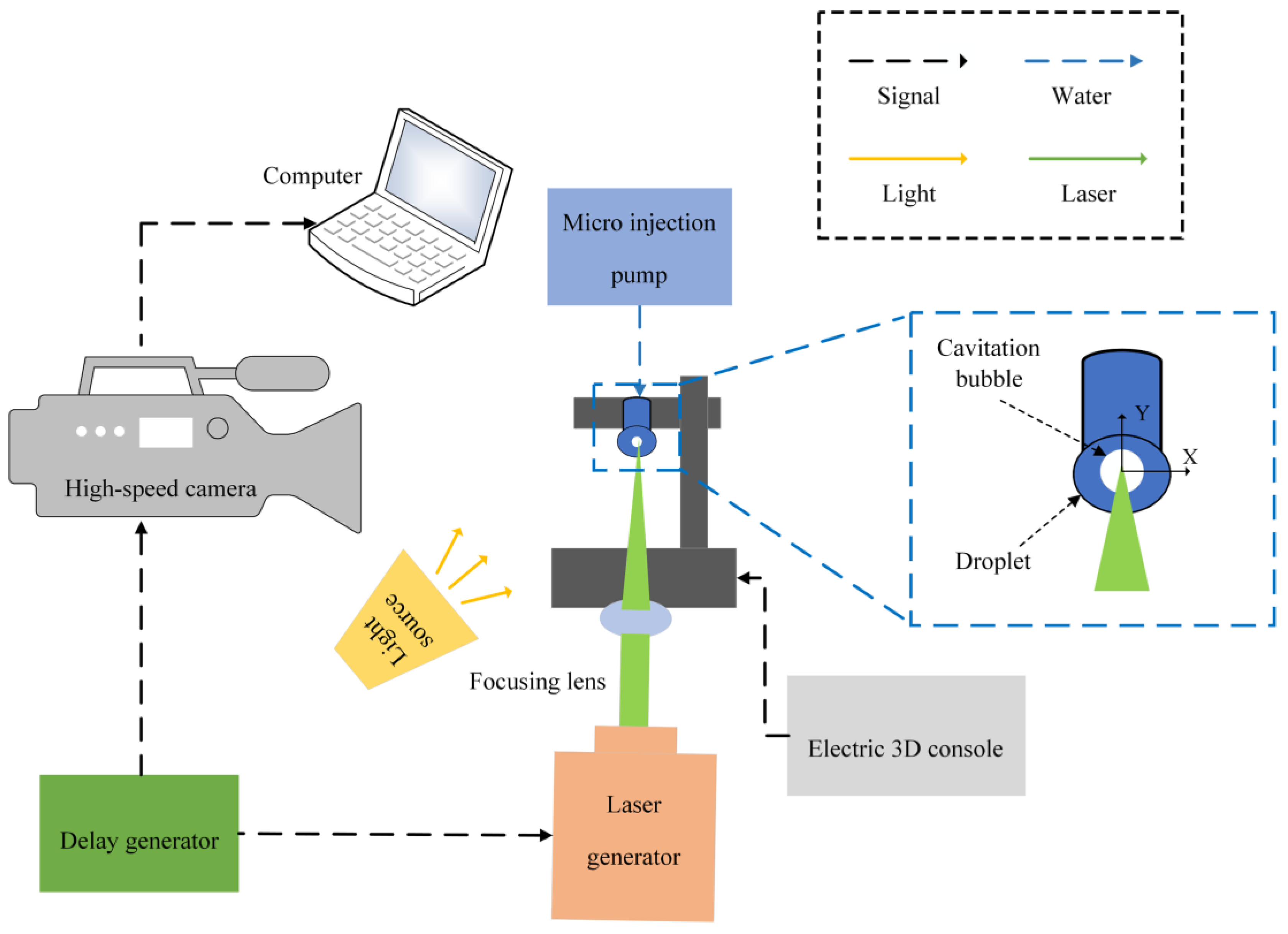
2.1. Experimental System

Figure 1 shows the high-speed photography experimental platform for laser-induced bubble in inverted droplet. The experiments were performed through combining the laser, the imaging system, and the lightings.

2.2. Definition of Feature Points and Radius Ratio

In order to explore the coupling effect between bubble collapse and splash of droplet, four feature points were selected on the bubble wall and droplet surface, respectively, and their dynamic processes were quantitatively analyzed and discussed.
Figure 2 shows the definition of feature points and radius ratio. The Cartesian coordinate system takes the point O as the origin. The intersection point between the positive X axial direction and the bubble wall is defined as Nbx; the intersection point between the negative Y axial direction and the bubble wall is defined as Nby; the intersection point between the lower left 45° axis and the bubble wall is defined as Nb45°; and the intersection point between the −45° axis at the bottom right and the bubble wall is defined as Nb−45°. The red dashed line is selected to represent the angle of the feature point, and the red circle represents the position of the feature point. As shown in Figure 2b, the parameter for the droplet is defined similarly.
Subfigure (c) shows the definition-related physical quantities of dimensionless parameter radius ratio λ. Rbx represents the radius of the short axis of the bubble and Rby represents the radius of the long axis of the bubble. Rdx represents the radius of the short axis of the droplet and Rdy represents the radius of the long axis of the droplet. The point O in the figure represents the initial position of the bubble, which is also the position of the cavitation in the droplet by the laser. In the experiment, the droplet is not completely spherical due to the effects of the pipeline and the droplet. After reasonable equivalence, the droplet and the bubble are regarded as ellipsoids. The dimensionless parameter radius ratio λ is defined as follows:
λ = ( R b x 2 R b y R d x 2 R d y ) 1 3

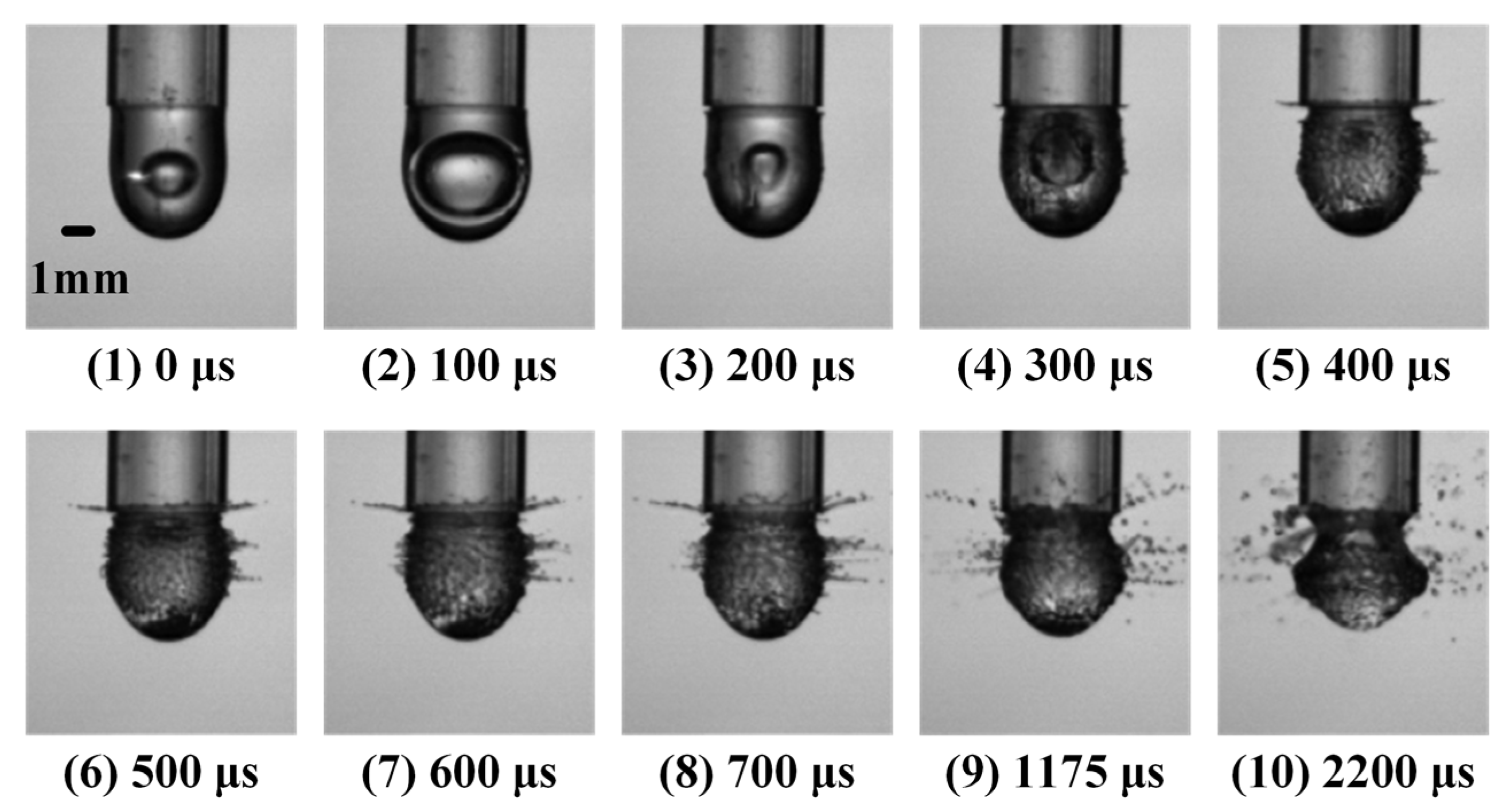
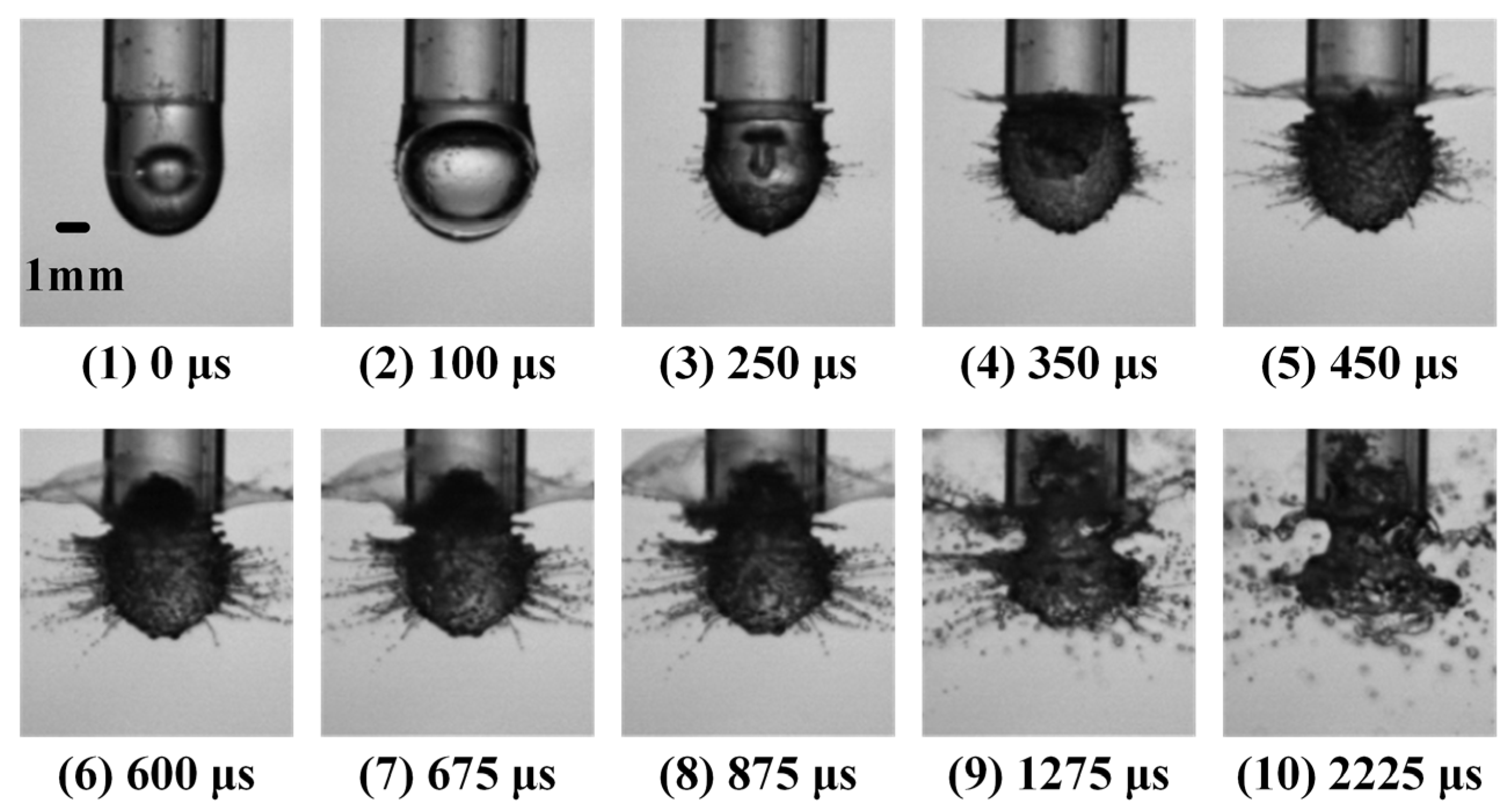
2.3. Three Typical Splash Cases

Figure 3 shows the process of bubble collapse within droplet with no splash on the surface of the droplet. Its main features include: the bubble wall of droplet is approximately ellipsoidal in shape, the center of mass of the bubble does not move significantly upwards, and there is no splash on the surface of the droplet. Under this condition, only slight deformation occurs at the connection between the droplet and the pipeline during the process of bubble collapse.
With the increase in λ, Figure 4 shows the process of bubble collapse within the droplet of scattering splash. During the first collapse of the droplet and bubble wall, there is a significant difference in the degree of contraction in the X and Y directions. Futhermore, a significant displacement of the droplet center of mass is shown together with a scattering splash at the droplet surface. Under this condition, due to the bubble collapse, the droplet morphology is significantly affected.
With a further increase in λ, Figure 5 shows the bubble collapse within droplet of a composite splash. Splash occurs immediately during the growth process of the bubble. At the first stage of collapse of the bubble, the wall of the bubble eventually contracts into a mushroom shape. At the second stage of collapse of the bubble, not only scattering splash appears on the surface of the droplet, but also an obvious flaky splash appears at the connection between the droplet and the pipeline, which is defined as composite splash. Under this condition, the impact of bubble collapse on droplet morphology is further enhanced.

3. Quantitative Analysis of No Splash

During the process of bubble collapse within a droplet of small λ, no splash of the droplet is shown. However, within a small λ range, λ can have a certain degree of impact on the dynamics of bubble collapse. Based on this, in this section, three typical experimental cases were selected, with λ of 0.463, 0.506, and 0.581, respectively. The displacement changes at the four feature points on the bubble wall with time were quantitatively compared. The variation of the displacement difference between the X axis vertices of bubble wall with different λ over time will be summarized. At the same time, four feature points were selected at the same directions of the droplet and the bubble, and the displacements of the feature points at the droplet surface with time were quantitatively compared. Finally, the variation of the displacement difference at the endpoint of the droplet surface X axis with time under different λ was discussed.

3.1. Bubble Feature Points

Figure 6 shows the displacement of bubble feature points of no splash of different λ over time in the no splash case. The red dash represents the displacement of feature points in the X axial direction; the blue double dotted line represents the displacement of feature points in the Y axial direction; the orange long line represents the displacement of feature points in the 45° axial direction; and the green dotted line represents the displacement of feature points in the −45° axial direction. Subfigure (a) shows the displacement of bubble feature point (λ = 0.463). During the first collapse, the displacement of the feature points from the maximum to the end of the first collapse was nearly 0.6 mm. The displacement in the 45° axial directions and X axis was closer to the displacement in the −45° axial direction. However, the displacement in the Y axial direction was slightly smaller than the displacements in the other three directions. Subfigure (b) (λ = 0.506) shows a similar trend to the subfigure (a).
However, subfigure (c) shows a different trend (λ = 0.581). Under this experimental condition, the trend of bubble collapse is obvious. Meanwhile, the variations of bubble wall shrinkage become significant.
Figure 7 shows the distance between the two ends of the bubble X axial corresponding to the three λ in the no splash case over time. It can be seen that the distance in the X axial direction of the bubble gradually decreases with time, which is the process of the bubble wall gradually shrinking. The larger λ, the greater the difference in initial displacement between the two ends of the X axial, and the longer the collapse time. In the no splash cases, the bubble collapse process has a significant lag when the λ is large.

3.2. Droplet Feature Points

Figure 8 shows the displacement of droplets of different λ over time in the no splash cases. Subfigure (a) shows the displacement of the droplet feature point (λ = 0.463). It can be seen that the displacement of feature points in the X and Y axial directions remains stable after a short period (100–500 μs). The displacement of droplet feature points in the 45° and −45° directions remains 0. Under this experimental condition, the droplet change is relatively small. There is a slight expansion in the X and Y axial directions, and the overall shape remains stable.
Subfigure (b) shows the displacement of droplet feature point (λ = 0.506). It can be seen that the X axial direction rises within the time range of 300 μs to 700 μs, with a displacement value of about 0.08 mm. The displacement of droplet feature points in the other three directions remains constant at 0. Under this experimental condition, the droplet has a significant impact on the X axial direction, but there is no significant change in other directions.
Subfigure (c) shows the displacement of droplet feature point (λ = 0.581). The displacement of the four feature points increases to a certain value within a time range of 100 μs to 500 μs and remains unchanged. The variations of droplet feature points in the Y direction and 45° direction is relatively quick (100 μs ~300 μs), while those in the X direction and −45° direction are slightly longer. In contrast, the degree of deformation at the droplet surface is less intensive than that of the bubble wall. As the λ increases, the overall trend of droplet feature point displacement increases.
Figure 9 shows the distance between the two ends of the droplet X axis corresponding to three λ over time in the case of no splash. It can be seen that the displacement of the droplet in the X axial direction decreases, firstly, and then remains constant. The larger λ, the larger the initial displacement of the droplet. The droplet reaches its maximum volume at the maximum volume of the bubble. As the bubble within the droplet collapses, the droplet oscillates slightly and then remains unchanged.

4. Quantitative Analysis of Scattering Splash

During the process of the bubble collapse of a droplet with a medium λ, droplet splashes mainly exhibit a scattering like a splash morphology. In this section, three typical experimental cases of scattering splash are selected, among which the λ values are: 0.825, 0.828, and 0.852, respectively. The research methodology is shown in Section 3.

4.1. Bubble Feature Points

Figure 10 shows the displacement of feature points of the bubble of different λ over time in the scattering splash case. In the scattering splash case, as the λ increases, the displacement of bubble feature points is significantly increased. In addition, as the λ increases, the motion of the cavitation bubble wall tends towards spherical contraction, and the anisotropy of bubble dynamics is weakened. This reflects the fact that the dynamics of the bubble are significantly influenced by the enhanced coupling effect between the droplet and bubble.
Figure 11 shows the distance between the two ends of the bubble X axis corresponding to three λ over time for the case of scattering splashes. The distance between the endpoints of the bubble X axis is decreased over time. The larger the λ, the longer the time for bubble collapse. In addition, the trend of curves with different λ remains basically consistent in this case.

4.2. Droplet Feature Points

Figure 12 shows displacement of feature points of a droplet of different λ over time in the scattering splash case. Comparing the displacement of the bubble with the displacement of the droplet features point in the cases of scattering splashes, it can be seen that the displacement of the droplet feature point in the X axial direction is relatively large in the cases of scattering splashes. As the λ increases, the displacement of the feature points in the X axial direction of the droplet is gradually increased, far higher than the displacement value of the feature points in other directions. This indicates that, under the experimental conditions of a scattering splash, the X axial direction of the droplet is greatly affected, resulting in a significant splash. The splash effect will be enhanced as the λ increases.
Figure 13 shows the distance between the two ends of the droplet scattering splash in the X axial direction. It can be seen that the X axial direction of the droplet is indicated to have significant splashes that gradually increased with the increase in λ. When λ is 0.825, the distance between the X axial direction endpoint of the droplet finally reaches about 5.8 mm. When the λ increases to 0.828 and 0.852, the distance eventually reaches about 10 mm. This indicates that splashing degree in the X axial direction is significantly affected as the λ increases in the scattering splash case.

5. Quantitative Analysis of Composite Splash

The splash of a droplet occurring in the large λ range mainly exhibits a composite splash. In this section, the composite splash with λ of 0.909, 0.926, and 0.953 are selected for the experiment, respectively. The research methodology is shown in Section 3.

5.1. Bubble Feature Points

Figure 14 shows the displacement of feature points of bubbles of different λ in the composite splash case. Comparing the feature point displacement curves of bubbles with different radius ratios under composite splash conditions, it can be seen that, as the λ increases, the difference in the displacement values of the four feature points of the bubble gradually decreases. This indicates that the force on the bubble interface becomes gradually uniform, and the development of anisotropy in the bubble wall is weakened, due to the coupling effect between the droplet and bubble.
Figure 15 shows the distance between two ends of a bubble of a composite splash in the X axial direction. It can be seen that the distance in the X axial direction of the bubble decreases with time in the case of a composite splash. The larger the radius ratio, the higher the initial displacement value. As time increases, the distance of the corresponding bubble with different λ gradually increases.

5.2. Droplet Feature Points

Figure 16 shows the displacement of feature points of droplets of different λ in the composite splash case. Comparing the feature point displacement curves of droplets with different λ in the cases of composite splashes, as the λ increases, the displacement value of the feature point in the X axial direction of the droplet increases significantly.
Figure 17 shows the distance between the two ends of droplets of composite splash in the X axial direction in the composite splash cases. It can be seen that, the greater λ, the greater the distance in the X axial direction of the droplet and the higher the slope of the curve.

6. Discussion of Collapse Time

The collapse time reflects the degree of the dynamics process of the bubble within a droplet. There exists a modification coefficient between the experimental value and the theoretical calculation value of the collapse time oscillating in infinite domains. The theoretical collapse time expression of the droplet bubble is as follows:
τ = T C T = T C R b max ( ρ / Δ p ) 1 / 2
Δ P = P P V
where TC represents the collapse time, τ represents the modification coefficient of the collapse time, Rbmax represents the maximum radius of the bubble, and Δ P is the difference between the pressure of the surroundings (101,325 Pa) and the ideal pressure for the vaporization (2335 Pa).
Figure 18 shows the modification coefficient of the bubble collapse time. According to the curve, it can be seen that the modification coefficient of the collapse time decreases with the increase in λ.

7. Conclusions

In this paper, three typical dynamic processes of cavitation bubbles within droplets are shown by building a high-speed photography experimental platform. The feature points at the interface between the bubble wall and the droplet are selected for quantitative comparative research. The variation in the dynamics of the bubble collapse and the splash of the droplet under different radius ratios are compared and discussed. Finally, the influence of the λ on the bubble collapse time is revealed. Under different splash cases, the dynamic of the cavitation bubble within a droplet’s feature points are significantly different. The main conclusions are as follows:
(1) Under the same splash case, the λ shows significant influences on the motion in the X direction in terms of feature point displacements.
(2) For different splash cases, there are significant differences in the trend of feature point displacement (especially in the X direction). As the λ increases, for the no splash case, the anisotropy during the bubble collapse increases while, for the case of scattering splash and composite splash, the anisotropy weakens.
(3) The modification coefficient of bubble collapse time is affected by the λ.

Author Contributions

Conceptualization, Y.Z. (Yuning Zhang 1) and X.Z.; methodology, Y.Z. (Yuning Zhang 1), and X.Z.; software, X.Z.; formal analysis, X.Z.; investigation, X.Z.; resources, Y.Z. (Yuning Zhang 1); data curation, X.Z.; writing—original draft preparation, X.Z.; writing—review and editing, Y.Z. (Yuning Zhang 1), Z.L. and Y.Z. (Yuning Zhang 2); visualization, S.Z., H.W. and K.Z.; supervision, Y.Z. (Yuning Zhang 1) and Y.Z. (Yuning Zhang 2); project administration, Y.Z. (Yuning Zhang 1); funding acquisition, Y.Z. (Yuning Zhang 1) and Y.Z. (Yuning Zhang 2). All authors have read and agreed to the published version of the manuscript.

Funding

This research was financially supported by the National Natural Science Foundation of China (Project Nos.: 51976056 and 52076215).

Institutional Review Board Statement

Not applicable.

Informed Consent Statement

Not applicable.

Data Availability Statement

Not applicable.

Acknowledgments

In this paper, regarding the format revision, experimental data processing, etc., the authors also thank Yihao Yang, Jiaze Ying and Xuan Du for their help.

Conflicts of Interest

The authors declare no conflict of interest.

References

  1. Salvador, F.J.; Martínez-López, J.; Caballer, M.; De Alfonso, C. Study of the influence of the needle lift on the internal flow and cavitation phenomenon in diesel injector nozzles by CFD using RANS methods. Energy Conv. Manag. 2013, 66, 246–256. [Google Scholar] [CrossRef] [Green Version]
  2. Som, S.; Ramirez, A.I.; Longman, D.E.; Aggarwal, S.K. Effect of nozzle orifice geometry on spray, combustion, and emission characteristics under diesel engine conditions. Fuel 2011, 90, 1267–1276. [Google Scholar] [CrossRef]
  3. Blessing, M.; König, G.; Krüger, C.; Michels, U.; Schwarz, V. Analysis of Flow and Cavitation Phenomena in Diesel Injection Nozzles and Its Effects on Spray and Mixture Formation. SAE Trans. 2003, 112, 1694–1706. [Google Scholar]
  4. Wang, X.; Su, W. A numerical study of cavitating flows in high-pressure diesel injection nozzle holes using a two-fluid model. Sci. Bull. 2009, 54, 1655–1662. [Google Scholar] [CrossRef]
  5. He, Z.; Zhong, W.; Wang, Q.; Jiang, Z.; Fu, Y. An investigation of transient nature of the cavitating flow in injector nozzles. Appl. Therm. Eng. 2013, 54, 56–64. [Google Scholar] [CrossRef]
  6. Ghiji, M.; Goldsworthy, L.; Brandner, P.A.; Garaniya, V.; Hield, P. Analysis of diesel spray dynamics using a compressible Eulerian/VOF/LES model and microscopic shadowgraphy. Fuel 2017, 188, 352–366. [Google Scholar] [CrossRef] [Green Version]
  7. Suh, H.K.; Lee, C.S. Effect of cavitation in nozzle orifice on the diesel fuel atomization characteristics. Int. J. Heat Fluid Flow 2008, 29, 1001–1009. [Google Scholar] [CrossRef]
  8. Yan, W. Experimental Study on Atomization Characteristics of Diesel Engine under Different Environmental Pressure and Temperature. Master’s Thesis, Beijing Jiaotong University, Beijing, China, 2018. [Google Scholar]
  9. Payri, R.; Garcia, J.; Salvador, F.; Gimeno, J. Using spray momentum flux measurements to understand the influence of diesel nozzle geometry on spray characteristics. Fuel 2005, 84, 551–561. [Google Scholar] [CrossRef]
  10. Lv, M.; Ning, Z.; Yan, K. The Instability of Vapor Bubble Growth within the Diesel Droplet under the Condition of Supercavitation. Adv. Mater. Res. 2012, 512–515, 477–480. [Google Scholar] [CrossRef]
  11. Kodama, T.; Tomita, Y. Cavitation bubble behavior and bubble–shock wave interaction near a gelatin surface as a study of in vivo bubble dynamics. Appl. Phys. B 2000, 70, 139–149. [Google Scholar] [CrossRef]
  12. Sankin, G.N.; Zhong, P. Interaction between shock wave and single inertial bubbles near an elastic boundary. Phys. Rev. E Cover. Stat. Nonlinear Biol. Soft Matter Phys. 2006, 74, 46304. [Google Scholar] [CrossRef] [Green Version]
  13. Arora, A.; Hakim, I.; Baxter, J.; Rathnasingham, R.; Srinivasan, R.; Fletcher, D.A.; Mitragotri, S. Needle-free delivery of macromolecules across the skin by nanoliter-volume pulsed microjets. Proc. Natl. Acad. Sci. USA 2007, 104, 4255–4260. [Google Scholar] [CrossRef] [PubMed]
  14. Baxter, J.; Mitragotri, S. Needle-free liquid jet injections: Mechanisms and applications. Expert Rev. Med. Devices 2014, 3, 565–574. [Google Scholar] [CrossRef] [PubMed]
  15. Fletcher, D.A.; Palanker, D.V.; Huie, P.; Miller, J.; Marmor, M.F.; Blumenkranz, M.S. Intravascular drug delivery with a pulsed liquid microjet. Arch. Ophthalmol. 2002, 120, 1206–1208. [Google Scholar] [CrossRef] [PubMed]
  16. Wang, L.; Zhu, B.; Huang, J.; Xiang, X.; Tang, Y.; Ma, L.; Yan, F.; Cheng, C.; Qiu, L. Ultrasound-targeted microbubble destruction augmented synergistic therapy of rheumatoid arthritisvia targeted liposomes. J. Mat. Chem. B 2020, 8, 5245–5256. [Google Scholar] [CrossRef]
  17. Martin, G.D.; Hoath, S.D.; Hutchings, I.M. Inkjet printing-the physics of manipulating liquid jets and drops. J. Phys. Conf. Ser. 2008, 105, 12001. [Google Scholar] [CrossRef]
  18. de Gans, B.J.; Duineveld, P.C.; Schubert, U.S. Inkjet Printing of Polymers: State of the Art and Future Developments. Adv. Mater. 2004, 16, 203–213. [Google Scholar] [CrossRef]
  19. Patrascioiu, A.; Fernández-Pradas, J.M.; Palla-Papavlu, A.; Morenza, J.L.; Serra, P. Laser-generated liquid microjets: Correlation between bubble dynamics and liquid ejection. Microfluid. Nanofluid. 2014, 16, 55–63. [Google Scholar] [CrossRef]
  20. Brown, M.S.; Kattamis, N.T.; Arnold, C.B. Time-resolved dynamics of laser-induced micro-jets from thin liquid films. Microfluid. Nanofluid. 2011, 11, 199–207. [Google Scholar] [CrossRef]
  21. Obreschkow, D.; Kobel, P.; Dorsaz, N.; de Bosset, A.; Nicollier, C.; Farhat, M. Cavitation bubble dynamics inside liquid drops in microgravity. Phys. Rev. Lett. 2006, 97, 94502. [Google Scholar] [CrossRef] [Green Version]
  22. Zhang, S.; Wang, S.P.; Zhang, A.M. Experimental study on the interaction between bubble and free surface using a high-voltage spark generator. Phys. Fluids 2016, 28, 32109. [Google Scholar] [CrossRef]
  23. Gonzalez Avila, S.R.; Ohl, C. Fragmentation of acoustically levitating droplets by laser-induced cavitation bubbles. J. Fluid Mech. 2016, 805, 551–576. [Google Scholar] [CrossRef]
  24. Lindau, O.; Lauterborn, W. Cinematographic observation of the collapse and rebound of a laser-produced cavitation bubble near a wall. J. Fluid Mech. 2003, 479, 327–348. [Google Scholar] [CrossRef]
  25. Liu, X.M.; He, J.; Lu, J.; Ni, X.W. Effect of surface tension on a liquid-jet produced by the collapse of a laser-induced bubble against a rigid boundary. Opt. Laser Technol. 2009, 41, 21–24. [Google Scholar] [CrossRef]
  26. Lü, M.; Ning, Z.; Yan, K.; Fu, J.; Song, Y.; Sun, C. Breakup of cavitation bubbles within the diesel droplet. Chin. J. Mech. Eng. 2014, 27, 198–204. [Google Scholar] [CrossRef]
  27. Kobel, P.; Obreschkow, D.; de Bosset, A.; Dorsaz, N.; Farhat, M. Techniques for generating centimetric drops in microgravity and application to cavitation studies. Exp. Fluids 2009, 47, 39–48. [Google Scholar] [CrossRef] [Green Version]
  28. Luo, X.; Gong, H.; Cao, J.; Yin, H.; Yan, Y.; He, L. Enhanced separation of water-in-oil emulsions using ultrasonic standing waves. Chem. Eng. Sci. 2019, 203, 285–292. [Google Scholar] [CrossRef]
  29. Kang, Y.J.; Cho, Y. Gravity-capillary jet-like surface waves generated by an underwater bubble. J. Fluid Mech. 2019, 866, 841–864. [Google Scholar] [CrossRef]
  30. Liang, Y.; Jiang, Y.; Wen, C.; Liu, Y. Interaction of a planar shock wave and a water droplet embedded with a vapour cavity. J. Fluid Mech. 2020, 885, R6. [Google Scholar] [CrossRef]
  31. Zeng, Q.; Gonzalez-Avila, S.R.; Voorde, S.T.; Ohl, C. Jetting of viscous droplets from cavitation-induced Rayleigh-Taylor instability. J. Fluid Mech. 2018, 846, 916–943. [Google Scholar] [CrossRef]
  32. Wang, J.; Li, H.; Guo, W.; Wang, Z.; Du, T.; Wang, Y.; Abe, A.; Huang, C. Rayleigh-Taylor instability of cylindrical water droplet induced by laser-produced cavitation bubble. J. Fluid Mech. 2021, 919, A42. [Google Scholar] [CrossRef]
Figure 1. The high-speed photography experimental platform of laser-induced bubble within the droplet.
Applsci 13 07862 g001
Figure 2. Definition of feature points and radius ratio. (a) Definition of bubble feature points; (b) definition of droplet feature points; and (c) definition-related physical quantities of λ.
Applsci 13 07862 g002
Figure 3. The process of bubble collapse within droplet with no splash.
Applsci 13 07862 g003
Figure 4. The process of bubble collapse within droplet with scattering splash.
Applsci 13 07862 g004
Figure 5. The process of bubble collapse within droplet with composite splash.
Applsci 13 07862 g005
Figure 6. Displacement of bubble feature points of no splash of different λ. (a) Displacement of bubble feature point (λ = 0.463); (b) displacement of bubble feature point (λ = 0.506); and (c) displacement of bubble feature point (λ = 0.581).
Applsci 13 07862 g006
Figure 7. Distance between two ends of the bubble of no splash in X axial direction.
Applsci 13 07862 g007
Figure 8. Displacement of droplet feature points of no splash of different λ. (a) Displacement of droplet feature point (λ = 0.463); (b) displacement of droplet feature point (λ = 0.506); and (c) displacement of droplet feature point (λ = 0.581).
Applsci 13 07862 g008
Figure 9. Distance between two ends of a droplet with no splash in the X axial direction.
Applsci 13 07862 g009
Figure 10. Displacement of bubble feature points of scattering splashes of different λ. (a) Displacement of bubble feature point (λ = 0.825); (b) displacement of bubble feature point (λ = 0.828); and (c) displacement of bubble feature point (λ = 0.852).
Applsci 13 07862 g010
Figure 11. Distance between two ends of the bubble of a scattering splash in X axial direction.
Applsci 13 07862 g011
Figure 12. Displacement of droplet feature points of scattering splashes of different λ. (a) Displacement of droplet feature point (λ = 0.825); (b) displacement of droplet feature point (λ = 0.828); and (c) displacement of droplet feature point (λ = 0.852).
Applsci 13 07862 g012
Figure 13. Distance between two ends of droplet of scattering splash in X axial direction.
Applsci 13 07862 g013
Figure 14. Displacement of bubble feature points of composite splashes of different λ. (a) Displacement of bubble feature point (λ = 0.909); (b) displacement of bubble feature point (λ = 0.926); and (c) displacement of bubble feature point (λ = 0.953).
Applsci 13 07862 g014
Figure 15. Distance between two ends of bubble of a composite splash in X axial direction.
Applsci 13 07862 g015
Figure 16. Displacement of droplet feature points of composite splashes of different λ. (a) Displacement of droplet feature point (λ = 0.909); (b) displacement of droplet feature point (λ = 0.926); and (c) displacement of droplet feature point (λ = 0.953).
Applsci 13 07862 g016
Figure 17. Distance between two ends of droplet of composite splash in X axial direction.
Applsci 13 07862 g017
Figure 18. Modification coefficient of bubble collapse time.
Applsci 13 07862 g018
Disclaimer/Publisher’s Note: The statements, opinions and data contained in all publications are solely those of the individual author(s) and contributor(s) and not of MDPI and/or the editor(s). MDPI and/or the editor(s) disclaim responsibility for any injury to people or property resulting from any ideas, methods, instructions or products referred to in the content.

