Article

Investigation of Load Environment and Bending Load Capacities of Aged Prestressed Concrete Sleepers

Railway Dynamics Division, Railway Technical Research Institute, 2-8-38 Hikari-cho, Kokubunji-shi, Tokyo 185-8540, Japan
*
Author to whom correspondence should be addressed.
Appl. Sci. 2023, 13(13), 7828; https://doi.org/10.3390/app13137828
Submission received: 22 May 2023 / Revised: 29 June 2023 / Accepted: 30 June 2023 / Published: 3 July 2023
(This article belongs to the Section Civil Engineering)

Abstract

:
In this study, field measurements of the bending moments of prestressed concrete (PC) sleepers installed on commercial lines were obtained, and numerical analyses to identify the effects of different parameters on their bending moments were conducted. The bending load capacities of aged PC sleepers collected from commercial lines via bending tests were also determined. According to the field measurement results of the wheel loads and bending moments of the PC sleepers, the measured values were smaller than the design values. In addition, neither the wheel load nor the bending moment depended on train speed. The numerical analysis results indicate that the positive bending moment at the rail seat section is unlikely to exceed the design decompression moment (DDM). However, the negative bending moment at the center section may exceed the DDM if center support is provided with a reduced spring constant under the rail (the “hanging” rail seat section). In addition, the bending moment increased with the rail surface roughness, so the rail should be kept smooth. Moreover, the results of the JIS E 1201 bending tests on the aged PC sleepers showed that the crack generation load and ultimate load decreased gradually with increases in age and passing tonnage. However, all samples satisfied the JIS standard values. Furthermore, the bending moments generated in the PC sleepers during train passage were considerably smaller than the crack generation load and ultimate load during the bending test. Thus, Japanese PC sleepers aged more than 50 years currently satisfy the standard flexural fracture values specified by the JIS, and safety is not immediately compromised.

1. Introduction

Sleepers are important track components that support rails, maintain the distance between the left and right rails, and distribute the load transmitted from the rails to the ballast. Prestressed concrete (PC) sleepers, the subject of this study, were installed for the first time in European countries, such as England and Germany, in the latter half of the 1940s. PC sleepers are widely used worldwide and are an indispensable track component for comfortable, safe, and stable high-speed railway transportation [1]. Japan’s PC sleepers were first installed on a trial basis in 1951. Since then, over 40 million sleepers have been built by Japanese National Railways and the Japan Railway Group alone (excluding private railway companies).
PC sleepers are generally expected to last approximately 50 years [1], but in recent years, a large number of PC sleepers have exceeded this life span. Therefore, various studies have been conducted on the evaluation of the service lives and remaining lives of aged PC sleepers [2]. The static and impact loads acting on PC sleepers should be considered in evaluating their service lives and remaining lives. Various studies have been vigorously performed worldwide on related topics, such as the examination of design methods [3,4,5] and the evaluation of impact loads [6,7,8,9]. In addition, studies have been conducted on the damage to PC sleepers [10], their fatigue lives considering abrasion [11], fatigue life evaluation methods based on wheel loads acting on PC sleepers [12], and fatigue life based on the bending moments generated in PC sleepers [13]. The support conditions of PC sleepers, which considerably affect the bending moments generated in PC sleepers, have likewise been studied [14,15,16]. Altogether, valuable information has been obtained for evaluating the service lives of PC sleepers.
In summary, researchers worldwide are exploring PC sleepers using various approaches. However, except for a few examples [2], researchers have not evaluated the load-bearing capacities of aged PC sleepers installed on commercial lines. Therefore, in the current study, we investigate the load environment of aged PC sleepers installed on commercial lines and evaluate their bending load capacities. Although the target PC sleepers in this study are limited to those in Japan, the actual load-bearing capacities of PC sleepers that have been used for nearly 50 years are evaluated. These results will be valuable for the literature on PC sleepers. In addition, the load environment evaluated in this study targets the straight section. Naturally, it is thought that the load environment will be different in curved sections and turnout sections, but we would like to address these issues in the future.
In Japan, maintenance vehicles run every day before the first Shinkansen trains run, and detailed track inspections are conducted. However, the soundness assessments of PC sleepers remain based on visual inspections, and this evaluation method is not necessarily linked to the load-bearing performances of the PC sleepers [17]. Contrary to the large number of installed PC sleepers, the number of sleepers that can be replaced in one night’s work is limited. Thus, if existing PC sleepers fail to meet their load-bearing capacities at a certain time, replacement work may fail to resolve the issue, and safety will be affected. To avoid this situation, Japan plans to set a quantitative service life and conduct systematic maintenance.
In this study, we address the following objectives to establish a new maintenance management system for PC sleepers:
(1)
To investigate the actual load environment of PC sleepers installed on commercial lines by measuring their bending moments.
(2)
To verify the effects of various parameters on the bending moments of PC sleepers via numerical analyses.
(3)
To collect a wide range of aged PC sleepers on commercial lines and evaluate their bending load capacities by conducting bending tests specified by the Japanese Industrial Standard (JIS) E 1201 [18].

2. Investigation of Load Environment of PC Sleepers

2.1. Investigation Methods

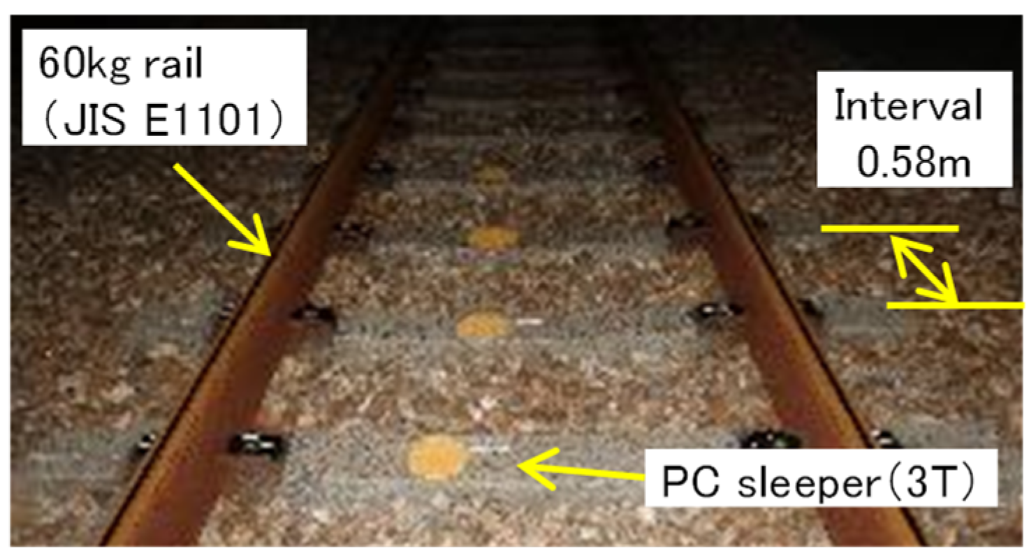
2.1.1. Outline of a PC Sleeper

Figure 1 shows the outline of a PC sleeper. The target PC sleepers are high-speed railway PC sleepers classified as 3T in the JIS E 1201. The length of one PC sleeper is 2400 mm, and the heights of its rail seat section and center section are 190 mm and 175 mm, respectively. The design standard strength of concrete is 49.1 N/mm2, and three φ2.9 mm strands constitute a PC steel strand. The design wheel load is 160 kN, which is double the 80 kN static wheel load based on the variable wheel load factor, which considers the dynamic components associated with train running. The target PC sleepers are designed to satisfy the full cross-sectional prestress against the design load [3,9].
Figure 2 shows the field measurement points. The location was a straight, ballasted track on a reinforced concrete viaduct, and trains passed at approximately 130–300 km/h. The PC sleepers were installed at intervals of 0.58 m, and the rails were 60 kg rails [19].

2.1.2. Methods of Measuring Wheel Loads and Bending Moments of PC Sleepers

Figure 3 shows the arrangement of the wheel load and concrete gauges attached to the rails and sleepers. Two strain gauges (Kyowa electronic instruments Co., Ltd., Japan) were attached to each sleeper: one at the upper end and one at the lower end of the rail seat section. The strains of five continuous PC sleepers were measured, and the measured strains were converted into bending moments. In addition, the strain gauges were connected to a National Instruments module that was connected to a personal computer using a LAN cable to save the data. The data were saved automatically using a LabVIEW program, with the vibration acceleration of the PC sleepers serving as the trigger for automatic saving. The sampling frequency was 10 kHz. In total, 337 trains were assessed.

2.1.3. Analysis Method

Figure 4 shows the outline of the 3D numerical analysis model used in this work. The simulation program Dynamic Interaction Analysis for Shinkansen Train and Railway Structures was used for numerical analysis [20,21,22].
Figure 4a shows the dynamic model of the vehicle, which was generated assuming that the body, bogies, and wheelsets were rigid. These rigid three-dimensional elements were linked by springs KN and dampers CN (N is a subscript number in Figure 4a) according to their characteristics. Each train car had 31 degrees of freedom. Each train consisted of multiple vehicle models linked together by springs KC and dampers CC attached to the ends of the vehicle models. The vehicles were given the specifications of a vehicle passing through the measurement point (a 56.6 kN static wheel load). The vehicle occupancy rate was set at 50%.
Figure 4b shows the dynamic model of the track, which was created using the finite element method. The track was modeled as a 160 m unit. The rails were modeled as beam elements, with each rail fastener divided into four segments by nodes. Each PC sleeper was modeled as a beam element divided into 10 segments by nodes. The track pads were modeled as spring elements. The ballast and roadbed were modeled as an integrated spring element. In total, the analysis models had 4634 nodes and 8468 elements. Since the measurement point was on a viaduct, the concrete member of the viaduct was assumed to be sufficiently rigid, and the boundary condition at the lower end of the spring element simulating the ballast was fixed. Figure 4c shows the rail surface roughness of the test section, which was statically measured using a surface roughness measuring device with a length of 1 m. The measured rail surface roughness was used to reproduce the exciting force generated between the wheel and the rail.
The equations of motion concerning the vehicle and the track were modally converted for numerical analysis efficiency. The resulting equations of motion on the modal coordinate system of the vehicle and the track were progressively solved in time increments of Δt using the Newmark method. For modal analysis, mode orders that can reproduce vibrations of up to approximately 10 kHz were used, and the analysis was executed at 0.1 msec intervals. An attenuation constant of 0.1 was used to ensure consistency with the time history response analysis [23].

2.1.4. Material Constants and Analysis Cases for Numerical Analysis

Table 1 shows the material constants in the numerical analysis. These constants were based on the Design Standards for Railway Structures and Commentary and nominal values [24,25].
In track maintenance in Japan, as shown in Figure 5a, the center sections of PC sleepers are generally not supported by ballasts (rail seat (center void) support) to reduce the reaction force from the ballast. However, in this study, assuming that a certain amount of time had passed since the latest track maintenance activity, the support conditions of the PC sleepers were assumed to be uniform rather than hollow (Figure 5b). Uniform support was set as the basic case.
Table 2 shows the analysis cases. We focused on the parameters for which constant fluctuations were assumed, specifically, the train speed, vehicle occupancy rate, rail surface irregularity, track pad spring constant, and ballast support spring constant. According to previous research, each value was set assuming its deterioration over time. Regarding the support conditions of the PC sleepers (last row of Table 2), as shown in Figure 5c, the support spring constant of an entire PC sleeper was reduced for only one evaluation sleeper, and the support spring constant under the rail was reduced (the range of the center support of 600 mm at the center did not reduce the spring constant). The underlined constants constituted the basic case. A total of 14,400 cases were analyzed.
As shown in Table 3, the rail surface roughness (Figure 6; 2500 μm maximum amplitude), measured at the rail joint of a conventional line, was set. The reason for this setting was that although this condition is unlikely to occur under general use conditions in Japan, it was established to verify the effect of its occurrence on the bending moments of PC sleepers.

2.2. Investigation Results

2.2.1. Measured Wheel Loads and Bending Moments of PC Sleepers

Figure 7 shows the measured wheel loads and bending moments. The maximum wheel load was 79.51 kN, and the maximum bending moment at the rail seat section of the PC sleeper was 3.81 kN·m. The maximum wheel load and bending moment are the largest wheel load and bending moment generated by each axle of one train set. Each value was compared with the corresponding design value. The measured values were smaller than the design values. The wheel load was 49.7% of the design wheel load of 160 kN, and the bending moment was 34.7% of the design decompression moment (DDM) of 10.95 kN·m. In addition, neither the wheel load nor the bending moment depended on speed. The reasons for the margin between the measured and design values included the fact that the actual wheel load was smaller than the design wheel load, the consideration of the variable wheel load coefficient, and the conservative assumption for the design’s lateral force and sleeper support condition.

2.2.2. Numerical Analysis Verification Results of Effects of Various Parameters on Bending Moments of PC Sleepers

Figure 8 shows a comparison of the analyzed and measured bending moments at the rail seat sections of the PC sleepers. The bending moment obtained from the data of 337 measurements was approximately 2.0 kN·m, which is the average value shown in Figure 7, at a train speed of 300 km/h. As can be seen in Figure 8, the analysis and measurement results were generally identical, and the actual average phenomenon was reproduced using the material constants in Table 1.
Figure 9 shows the numerical analysis results of the effects of the parameters on the positive bending moments at the rail seat sections. Figure 9a–g show the effects of each parameter on the basic case. The yellow plot in the figure is the basic case. According to Figure 9, similar to the measurement results, the bending moment did not depend on the train speed and increased with the vehicle occupancy rate, the spring constants of the track pad and ballast, and the rail surface roughness. In addition, when the support spring constant of a PC sleeper decreased, the adjacent PC sleeper bore the load, so the bending moment of the PC sleeper decreased.
Figure 10 shows the numerical analysis results of the effects of the parameters on the negative bending moments at the center sections. Only the results of the support conditions of the PC sleepers are shown here. The descriptions of the other parameters are omitted because they are similar to those shown in Figure 9. Figure 10a shows the result of a PC sleeper with a uniform support with a reduced spring constant; the trend is almost the same as that in Figure 9f. Figure 10b shows the result of the center support, where the negative bending moment at the center section of the PC sleeper greatly increased. Specifically, when the support spring constants at the rail seat section were 1/2, 1/10, and 1/100 of the constant at the center section, the bending moments at the center sections were approximately doubled, approximately quintupled, and approximately nonupled, respectively. PC sleepers are commonly provided rail seat (central void) support during track maintenance. Our findings suggest the possibility of increasing the negative bending moments at the center sections of PC sleepers by providing center support.
Figure 11 shows the numerical analysis results of all cases shown in Table 2. As shown in the figure, the positive bending moment at the rail seat section did not exceed the DDM. In the cases in which the sleeper was uniformly supported or the spring constant under the rail was reduced to 1/2, 1/5, or 1/10 of that at the center section, the negative bending moment at the center section did not exceed the DDM. In contrast, when the spring constant under the rail was 1/100 of that at the center section, this bending moment exceeded the DDM.
Figure 12 shows the numerical analysis results of the case in which the rail surface roughness was measured at the rail joint of the conventional line (Figure 6). Shinkansen trains do not encounter this scenario, but if the amplitude of the rail surface roughness ever becomes approximately 2.5 mm, such as at the rail joints, the bending moment may exceed the DDM. Furthermore, if the amplitude becomes approximately 7.5 mm, the bending moment may also exceed the yield moment of steel.
The above results indicate that the primary factor causing cracks and bending fractures in the target PC sleepers was the rail surface roughness, which had large local amplitudes, such as at the rail joints. In addition, assuming the PC sleepers had center support, the negative bending moments at the centers of the sleepers may increase. Therefore, the current track maintenance practice in Japan, that is, providing PC sleepers with rail seat (central void) support, should be continued. Although wheel flats were not considered in this study, their effects should be verified in the future because they generate impact loads in the same way as rail surface roughness [3,26,27,28]. However, if the current maintenance level of wheel surfaces in Japan is maintained, impact load due to wheel flats will be unlikely, so the numerical analysis in this study is worth evaluating.

3. Evaluation of Bending Load Capacities of Aged PC Sleepers

3.1. Test Methods

3.1.1. Collection of PC Sleepers

Table 3 shows the number of collected PC sleepers. The target PC sleepers are those specified in the JIS E 1201 (type 3T; Chapter 2). These sleepers were placed in the same line section as the site where the field measurement (Chapter 2) was conducted, and they were aged 10–60 years.

3.1.2. JIS E 1201 Bending Test

Figure 13 shows an outline of the bending test specified in the JIS E 1201 [18]. Positive and negative bending tests were conducted on the rail seat and center sections of the PC sleepers, respectively. The loading span was 700 mm. The flexural proof load Pcr and flexural fracture load Pu specified in JIS E 1201 were obtained using Equations (1) and (2), respectively. In the test, no cracks occurred when the Pcr was applied, and the PC sleepers did not break when the Pu was applied.
Pcr = 4 × (σCPr × 0.9 + f ta) × Z/L
Pu = 4 × 3σpe × Z/L
where σCPr is the concrete stress due to the applied prestress force, f ta is the allowable tensile stress (3 N/mm2), σpe is the concrete stress due to the effective prestress force (65% effective rate), Z is the section modulus, and L is the loading span (700 mm). Regarding test results, the relationship between the aging and accumulative passing tonnage (hereafter, the “passing tonnage”) was determined for the crack generation and ultimate loads. The crack generation load was the load at which a crack was first detected via visual observation. The ultimate load was the maximum load, past which the PC sleeper could no longer hold the load due to bending.

3.2. Test Results

Figure 14 and Figure 15 show the bending test results, including the flexural proof load and the flexural fracture load. The figures indicate that the crack generation load and the ultimate load decrease gradually with increases in age and passing tonnage. The crack generation load and the ultimate loads of all PC sleepers satisfied the JIS standard values of Pcr and Pu. In addition, the right axes of these figures show the bending moments generated in the PC sleepers. As shown in Figure 7, the bending moments generated in the PC sleepers during actual train passage were quite small compared with the crack generation loads and ultimate loads during the bending tests. Furthermore, the bending moment obtained from the numerical analysis (Figure 11), except for the analysis results involving the rail surface roughness at the rail joints (Figure 12), was smaller than the crack generation load in the bending tests.
The above results indicate that at present, even aged PC sleepers that are approximately 50 years old satisfy the standard Pcr and Pu values specified by the JIS, and safety is not immediately compromised. However, the bending load-bearing capacity decreases with age and an increase in passing tonnage. Sudden, continuous, non-satisfying bending load-bearing performance should be avoided at any given time. In the future, a quantitative service life should be established, and a shift to a systematic maintenance management system is necessary.

4. Conclusions

In this study, the actual load environment of PC sleepers was investigated via field measurements on commercial lines. In addition, numerical analyses were conducted to verify the effects of various parameters on the bending moments of PC sleepers. Moreover, aged PC sleepers installed on commercial lines were collected and subjected to bending tests specified in JIS E 1201 to evaluate their bending load capacities. The findings of this study are summarized below.
(1)
According to the field measurement results of the wheel loads and bending moments of the PC sleepers, the maximum wheel load was 79.51 kN and the maximum bending moment at the rail seat section was 3.81 kN·m. The measured values were smaller than the design values. The wheel load was 49.7% of the design wheel load of 160 kN, whereas the bending moment was 34.7% of the DDM of 10.95 kN·m. In addition, neither the wheel load nor the bending moment depended on train speed.
(2)
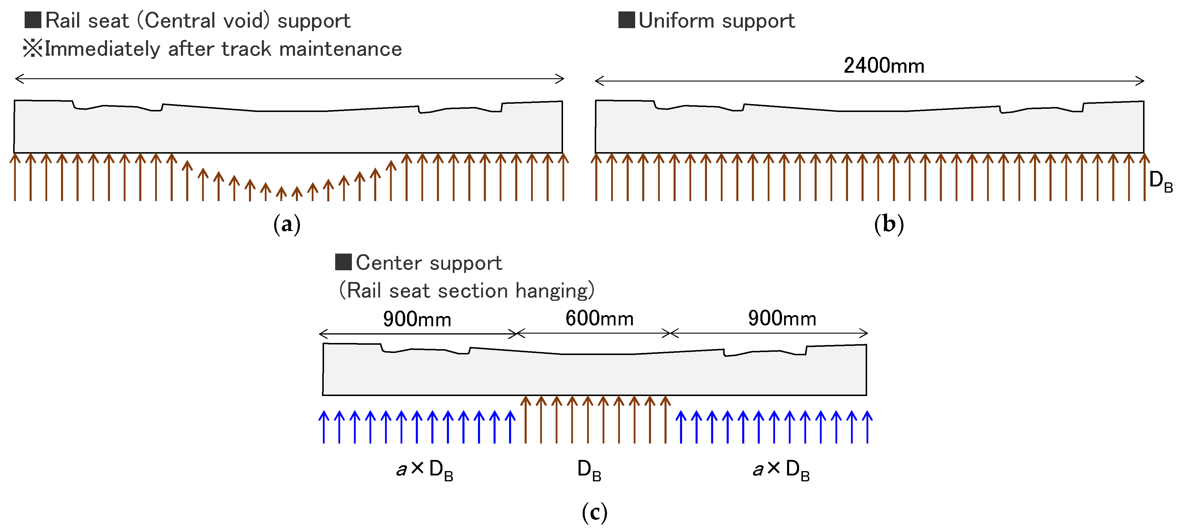
The numerical analysis results indicated that the positive bending moment at the rail seat section was unlikely to exceed the DDM. However, the negative bending moment at the center section may exceed the DDM if center support were provided with a reduced spring constant under the rail (the “hanging” rail seat section). In addition, the bending moment increased with the rail surface roughness, so the rail should be kept smooth.
(3)
The results of the JIS E 1201 bending tests on the aged PC sleepers showed that the crack generation load and ultimate load decreased gradually with increases in age and passing tonnage. However, all samples satisfied the JIS standard Pcr and Pu values. Furthermore, the bending moments generated in the PC sleepers during train passage were considerably smaller than the crack generation loads and ultimate loads during the bending tests.
(4)
Thus, Japanese PC sleepers aged over 50 years currently satisfy the standard flexural fracture values specified by the JIS, and safety is not immediately compromised.
In the future, we plan to formulate a maintenance management plan and a replacement plan for PC sleepers according to the service life of a PC sleeper obtained in this study. We also recommend the continuation of maintenance and management practices that do not generate impact loads. Present track maintenance work, which involves the use of rail seat (central void) support for PC sleepers and is commonly practiced today, should also be continued to maintain the safety and stability of railway transportation.

Author Contributions

Conceptualization, T.W.; methodology, T.W., K.G. and S.M.; software, T.W. and K.G.; validation, T.W., K.G. and S.M.; formal analysis, T.W.; investigation, T.W., K.G. and S.M.; resources, T.W.; data curation, T.W.; writing—original draft preparation, T.W.; writing—review and editing, T.W.; visualization, T.W.; supervision, T.W.; project administration, T.W. All authors have read and agreed to the published version of the manuscript.

Funding

This research received no external funding.

Institutional Review Board Statement

Not applicable.

Informed Consent Statement

Not applicable.

Data Availability Statement

Not applicable.

Acknowledgments

The authors would like to thank the West Japan Railway Company for the significant cooperation in some field measurements of this study.

Conflicts of Interest

The authors declare no conflict of interest.

References

  1. FIP Commission on Prefabrication. FIP State of the Art Report (Concrete Railway Sleepers); Thomas Telford Ltd.: London, UK, 1987. [Google Scholar]
  2. Remennikov, A.M.; Kaewunruen, S. Experimental load rating of aged railway concrete sleepers. Eng. Struct. 2014, 76, 147–162. [Google Scholar] [CrossRef]
  3. Wakui, H.; Okuda, H. A study on limit state design method for prestressed concrete sleepers. Concr. Libr. JSCE 1999, 33, 1–25. [Google Scholar] [CrossRef] [PubMed] [Green Version]
  4. Kaewunruen, S.; Remennikov, A.M.; Murray, M.H. Introducing a new limit states design concept to railway concrete sleepers: An Australian experience. Front. Mater. 2014, 1, 8. [Google Scholar] [CrossRef]
  5. Ruiz, A.E.C.; Edwards, J.R.; Qian, Y.; Dersch, M.S. Probabilistic framework for the assessment of the flexural design of concrete sleepers. Proc. IMechE Part F J. Rail Rapid Transit 2020, 234, 691–701. [Google Scholar] [CrossRef]
  6. Remennikov, A.M.; Kaewunruen, S. A review of loading conditions for railway track structures due to train and track vertical interaction. Struct. Control Health Monit. 2007, 15, 207–234. [Google Scholar] [CrossRef]
  7. Remennikov, A.M.; Murray, M.H.; Kaewunruen, S. Reliability-based conversion of a structural design code for railway prestressed concrete sleepers. Proc. IMechE Part F J. Rail Rapid Transit 2011, 226, 155–173. [Google Scholar] [CrossRef]
  8. Hamarat, M.; Papaelias, M.; Silvast, M.; Kaewunruen, S. The Effect of Unsupported Sleepers/Bearers on Dynamic Phenomena of a Railway Turnout System under Impact Loads. Appl. Sci. 2020, 10, 2320. [Google Scholar] [CrossRef] [Green Version]
  9. Watanabe, T.; Goto, K.; Matsuoka, K.; Minoura, S. Validation of a dynamic wheel load factor and the influence of various track irregularities on the dynamic response of prestressed concrete sleepers. Proc. IMechE Part F J. Rail Rapid Transit 2020, 234, 1275–1284. [Google Scholar] [CrossRef]
  10. You, R.; Wang, J.; Ning, N.; Wang, M.; Zhang, J. The Typical Damage Form and Mechanism of a Railway Prestressed Concrete Sleeper. Materials 2022, 15, 8074. [Google Scholar] [CrossRef] [PubMed]
  11. Li, D.; Kaewunruen, S.; You, R. Remaining Fatigue Life Predictions of Railway Prestressed Concrete Sleepers Considering Time-Dependent Surface Abrasion. Sustainability 2022, 14, 11237. [Google Scholar] [CrossRef]
  12. You, R.; Li, D.; Ngamkhanong, C.; Janeliukstis, R.; Kaewunruen, S. Fatigue Life Assessment Method for Prestressed Concrete Sleepers. Front. Built Environ. 2017, 3, 68. [Google Scholar] [CrossRef] [Green Version]
  13. Goto, K.; Watanabe, T.; Minoura, S.; Ikeda, M. Fatigue Life Evaluation of PC Sleepers Based on Wheel Load Measurement Results. Q. Rep. RTRI 2022, 63, 263–268. [Google Scholar] [CrossRef] [PubMed]
  14. Kaewunruen, S.; Remennikov, A.M. Investigation of free vibrations of voided concrete sleepers in railway track system. Proc. IMechE Part F J. Rail Rapid Transit 2007, 221, 495–507. [Google Scholar] [CrossRef]
  15. Lazarević, L.; Vučković, D.; Popović, Z. Assessment of sleeper support conditions using micro-tremor analysis. Proc. IMechE Part F J. Rail Rapid Transit 2016, 230, 1828–1841. [Google Scholar] [CrossRef]
  16. Quirós-Orozco, R.J.; Edwards, J.R.; Dersch, M.S. Variability of support conditions and effects on the non-linear flexural response of concrete sleepers. Proc. IMechE Part F J. Rail Rapid Transit 2022, 236, 950–959. [Google Scholar] [CrossRef]
  17. Railway Technical Research Institute. Maintenance Standards for Railway Structures and Commentary (Track Structures); Railway Technical Research Institute: Tokyo, Japan; Maruzen Co., Ltd.: Tokyo, Japan, 2007. [Google Scholar]
  18. JIS E1201; Prestressed Concrete Sleepers-Pretensioning Type. Japanese Standards Association: Tokyo, Japan, 1997.
  19. JIS E1101; Flat Bottom Railway Rails and Special Rails for Switches and Crossings of Non-Treated Steel. Japanese Standards Association: Tokyo, Japan, 1980.
  20. Hajime, W.; Nobuyuki, M.; Makoto, T. A study on dynamic interaction analysis for railway vehicle and structures. Q. Rep. Railw. Tech. Res. Inst. 1994, 35, 96–104. [Google Scholar]
  21. Tanabe, M.; Matsumoto, N.; Wakui, H.; Sogabe, M. Simulation of a Shinkansen train on the railway structure during an earthquake. Jpn. J. Ind. Appl. Math. 2011, 28, 223–236. [Google Scholar] [CrossRef]
  22. Tanabe, M.; Komiya, S.; Wakui, H.; Matsumoto, N.; Sogabe, M. Simulation and visualization of high-speed Shinkansen train on the railway structure. Jpn. J. Ind. Appl. Math. 2000, 17, 309–320. [Google Scholar] [CrossRef]
  23. Matsuoka, K.; Watanabe, T. Application of a frequency-based detection method for evaluating damaged concrete sleepers. In Advances in Structural Health Monitoring; IntechOpen: Rijeka, Croatia, 2018. [Google Scholar]
  24. Railway Technical Research Institute. Design Standards for Railway Structures and Commentary (Track Structures); Railway Technical Research Institute: Tokyo, Japan; Maruzen Co., Ltd.: Tokyo, Japan, 2012. [Google Scholar]
  25. Railway Technical Research Institute. Design Standards for Railway Structures and Commentary (Concrete Structures); Railway Technical Research Institute: Tokyo, Japan; Maruzen Co., Ltd.: Tokyo, Japan, 2007. [Google Scholar]
  26. Zhang, Z.; Wei, S.; Andrawes, B.; Kuchma, D.A.; Edwards, J.R. Numerical and experimental study on dynamic behavior of concrete sleeper track caused by wheel flat. Int. J. Rail Transp. 2016, 4, 1–19. [Google Scholar] [CrossRef]
  27. Vyas, N.S.; Gupta, A.K. Modeling rail wheel-flat dynamics. In Proceedings of the 1st World Congress on Engineering Asset Management (WCEAM), Ho Chi Minh City, Vietnam, 18–20 October 2006; pp. 11–14. [Google Scholar]
  28. Bian, J.; Gu, Y.T.; Murray, M. Numerical Study of Impact Forces on Railway Sleepers under Wheel Flat. Adv. Struct. Eng. 2013, 16, 127–134. [Google Scholar] [CrossRef]
Figure 1. Outline of PC sleeper (classified as 3T in JIS E 1201).
Applsci 13 07828 g001
Figure 2. Field measurement points.
Applsci 13 07828 g002
Figure 3. Arrangement of wheel load gauge and concrete gauge.
Applsci 13 07828 g003
Figure 4. Outline of 3D numerical analysis model. (a) Dynamic model of vehicle; (b) dynamic model of track; (c) rail surface roughness.
Applsci 13 07828 g004
Figure 5. Support conditions of PC sleepers: (a) rail seat (central void) support; (b) uniform support; (c) center support.
Applsci 13 07828 g005
Figure 6. Rail surface roughness at rail joint of conventional line.
Applsci 13 07828 g006
Figure 7. Measurement results: (a) wheel loads; (b) bending moments (five continuous sleepers).
Applsci 13 07828 g007
Figure 8. Comparison of analysis and measurement results.
Applsci 13 07828 g008
Figure 9. Numerical analysis results of effects of various parameters on bending moments at rail seat sections: (a) trail speed; (b) vehicle occupancy rate; (c) spring constant of track pad; (d) spring constant of ballast; (e) amplitude of rail surface roughness; (f) support condition R (Table 2); (g) support condition C (Table 2).
Applsci 13 07828 g009
Figure 10. Numerical analysis results of effects of various parameters on bending moment at center section. (a) Support condition R (Table 2); (b) support condition C (Table 2).
Applsci 13 07828 g010
Figure 11. Numerical analysis results of all cases. (a) Rail seat section; (b) center section.
Applsci 13 07828 g011
Figure 12. Numerical analysis results of the case in which rail surface roughness is measured at rail joint of conventional line (Figure 6).
Applsci 13 07828 g012
Figure 13. Outline of JIS E 1201 bending test.
Applsci 13 07828 g013
Figure 14. Relationship between bending load-bearing capacities of PC sleepers and passing tonnage. (a) Positive bending moments at rail seat section; (b) negative bending moments at center sections.
Applsci 13 07828 g014
Figure 15. Relationship between bending load-bearing capacities and ages of PC sleepers. (a) positive bending moments at rail seat sections; (b) negative bending moments at center sections.
Applsci 13 07828 g015
Table 1. Material constants used in numerical analysis.
Material Constants
Rail60 kg rail (JIS E 1101; Young’s modulus ES = 200 GPa)
Track gauge = 1435 mm
Track padSpring constant DP = 50 MN/m
SleeperType 3T (JIS E 1201), PC steel strand = φ 2.9 mm, N = 16
Length LP = 2400 mm
Bottom width BP = 283 mm (rail seat section), 230 mm (center section)
Height HP = 190 mm (rail seat section), 175 mm (center section)
Young’s modulus EC = 33 GPa
BallastBallast thickness h = 250 mm
Support spring constant DB = 200 MN/m (per rail)
Table 2. Analysis cases.
ParameterConstant
Train speed (km/h)200, 250, 270, 300, 320
Vehicle occupancy rate (%)50, 100, 200
Spring constant of track pad (MN/m)50, 100, 150, 250
Spring constant of ballast (MN/m)10, 30, 50, 100, 200
Rail surface roughnessNone, original (measured on-site), three times the original, and five times the original
Support condition of PC sleeperUniform support
Uniform support with reduced spring constant (α × DB) (support condition R)
Center support (α × DB) (support condition C)
α = 1/100, 1/10, 1/2, 4/5
The underlined constants constitute the basic case.
Table 3. Number of PC sleepers.
Age~10~20~30~40~50~60Total
Number332148434
Disclaimer/Publisher’s Note: The statements, opinions and data contained in all publications are solely those of the individual author(s) and contributor(s) and not of MDPI and/or the editor(s). MDPI and/or the editor(s) disclaim responsibility for any injury to people or property resulting from any ideas, methods, instructions or products referred to in the content.

