Article

Deck Slab Elements for the Accelerated Construction of Steel–Concrete Composite Bridges

Institute of Structural Engineering, TU Wien, Karlsplatz 13/E212-2, 1040 Vienna, Austria
*
Author to whom correspondence should be addressed.
Appl. Sci. 2023, 13(13), 7825; https://doi.org/10.3390/app13137825
Submission received: 2 June 2023 / Revised: 26 June 2023 / Accepted: 28 June 2023 / Published: 3 July 2023
(This article belongs to the Section Civil Engineering)

Abstract

:
Various methods have been developed to produce deck slabs for steel–concrete composite bridges. Usually, the deck slabs are cast with in situ concrete using a formwork carriage, resulting in construction progress of 15 to 25 m of deck slab per week. A new construction method was developed at the Institute of Structural Engineering (TU Wien), which enables the swift erection of the concrete deck slab. This method employs precast deck slab elements with reinforced concrete cross-beams which span in the transverse direction. With this new construction method, producing up to two deck slab sections of 15–25 m per day becomes possible. Further, the performance of novel reinforcement detailing required for the precast deck slab elements is investigated by structural testing. The experiments consist of eight load-bearing tests on four specimens which represent sections of the element during casting and after completion. The investigated parameters in series 1 are the length and spacing of loops, used for protruding longitudinal bars enclosure. In series 2, the enclosure of the shear reinforcement and the height of the cross beams are varied. The results show that the targeted bending capacity could be reached in all tests with no signs of premature failure due to detailing reasons. Based on the experimental results, the feasibility of the new approach is shown and recommendations for detailing are given.

1. Introduction

In the construction of steel–concrete composite bridges, the production of the concrete deck slabs is usually critical in terms of the time path [1]. Various techniques for the construction of concrete deck slab have been developed to keep up with the fast construction process of steel superstructures. A distinction can be made between building the deck slab with cast-in-place (CIP) concrete or prefabricated elements. When building with precast elements, a differentiation can be made between half- and full-depth elements [2]. Since the construction speed of the deck slab significantly influences the economic efficiency of steel–concrete composite bridges [1], many advanced accelerated construction solutions have already been developed (see Section 1.2). The total expenses for a bridge or roadway project are not limited to the amount spent on materials and labor. In addition, user costs must be considered [3]. According to Hällmark et al. [3], construction sites disrupt the typical traffic flow around the project area, leading to inefficient distribution of goods and longer waiting times. Therefore, accelerated construction of engineering structures is paramount for all involved.

1.1. Construction Methods with CIP Concrete

A time-consuming but proven method is casting the deck slab on stationary formwork. Figure 1a shows the erection of the deck slab with formwork attached to the steel girders. A combination of falsework and formwork can also be used. The assembly and disassembly of the formwork will need a considerable amount of time. This method is usually used for bridges with short spans and where the factor of time plays a minor role.
Figure 1b illustrates a rather sophisticated and widely used method. In this case, a formwork carriage is used to cast individual construction sections, for example, at weekly intervals. The length of a single construction section depends on the size of the carriage and ranges from 15 to 25 m. To move the carriage to the next casting section, a roller support system is attached to the upper chord of the steel structure. Additionally, the concrete must have sufficient strength for the formwork to be removed.
Methods using CIP concrete have the advantage of producing high-quality deck slabs, which ensures high durability.

1.2. Construction Methods with Prefabricated Elements

A significantly faster process of deck slab construction can be achieved using prefabricated elements. Several building methods utilizing half- and full-depth elements have been developed in recent decades. Comprehensive overviews of different techniques for slab building with prefabricated elements for steel–concrete composite bridges are presented in [1,4]. In construction methods using prefabricated elements, vertical and horizontal joints inevitably occur due to the division of the deck slab into several segments. Particularly in the case of full-depth elements, the resulting joints extend over the entire height of the concrete slab cross-section (see Figure 2). Durability problems are often associated with joints [5]. This has resulted in a reluctance to use prefabricated elements in some countries (e.g., Germany, Austria, and Switzerland). Other countries, such as the USA, Japan, China, India and France, have adhered to the construction method with prefabricated elements and now have a substantial inventory of steel–concrete composite bridges, where the deck slab was built with precast elements [6].

1.2.1. Full-Depth Elements

When building the deck slab with full-depth precast elements, the elements are placed next to each other on the already completed steel structure. By placing the elements side by side, a continuous vertical joint over the entire height of the cross-section of the slab is unavoidably obtained. In the past, several solutions for the connections of segments for precast segmental bridges have been developed [7]. These same methods have also been used to form the joint of full-depth precast elements for the deck slab. Essentially, a distinction is drawn between: (a) reinforced CIP concrete joints (Figure 2), (b) unreinforced mortar joints, (c) epoxy joints and (d) dry joints.
The usual connection is a reinforced joint. This solution has advantages when it comes to accuracy of the precast elements and the need for match casting [7]. Therefore, the reinforcement projects from the edges of the elements. In most cases, additional reinforcement is installed at the construction site. The joint is then closed with CIP concrete. This method was applied at the Bahretal bridge in Germany [8,9].
Figure 2. Stitching detail of transverse joint of Bahretal bridge [9]. Photo courtesy of company group Max Bögl/Johann Schlapschy.
Applsci 13 07825 g002

1.2.2. Half-Depth Elements

When building deck slabs with half-depth elements, CIP concrete must still be poured at the construction site to complete the deck slab. The half-depth elements act as a permanent formwork system. In many cases, a large part of the reinforcement is already present in the precast elements so that it can be fully included in the structural analysis. An advantage of producing the deck slab with half-depth elements can be seen in the comparatively lightweight precast elements, which accommodate the transportation restrictions. Another benefit of using half-depth elements in terms of durability is that no vertical joint over the entire height of the cross-section arises due to the top layer of CIP concrete.
Doss et al. [10] proposed a method where a thin plate is already cast in the factory on top of a steel girder and connected using shear connectors, e.g., shear studs, which are welded to the top chord (Figure 3). The width of the thin concrete plate is usually limited to the maximum transport width in the respective country. The transport width should not exceed 2.55 m (Europe) to avoid special transport [11]. In addition, shear connectors protrude from the thin plate to create a sufficient bond with the CIP concrete. The composite steel girders are placed on the abutments at the construction site, and the joints between the thin plates are sealed. This construction method is intended for bridge structures over already existing infrastructure routes, where no long-lasting interruptions of these should occur. The use of the VFT® (german abbr. for precast composite beam) construction method requires a relatively high number of longitudinal girders. This is due to the closing of the longitudinal joint between the thin precast concrete plates and the hauling restrictions.
Another method for constructing the deck slab was used in Germany when building the Wupper River valley bridge Oehde [12]. In this case, a steel–concrete composite bridge was erected with seven spans between 44.0 and 72.8 m and a total length of 418.3 m. The steel structure, a U-shaped box beam, was brought into its final position using the incremental launching method. The concrete deck slab was built with partial-depth precast elements (Figure 4), placed on elastomeric strips and an additional CIP concrete layer. The shear connection between the steel and the concrete structure was achieved with shear studs, which were welded to the top chord of the U-shaped box beam. For the overhangs in the cross-section, an auxiliary steel structure with inclined struts was attached to the U-shaped box beam to provide sufficient support for the partial-depth precast elements. The static system for the precast elements thus consisted of four bearings with two support strips each. Using this method, the lengths of the cantilevers in the cross-section are limited due to the low effective depth d of the precast elements. Similar solutions with partial-depth precast elements were also proposed by Badie et al. [13] and Lühr et al. [14].
A combination of thin partial-depth precast elements, which serve as a permanent formwork system and a top CIP concrete layer, was developed at TU Wien [15]. The production of the deck slab is based on the principle of the formwork carriage method with CIP concrete. Instead of formwork made from multilayer wood panels, thin precast elements are used. Under industrial conditions, slab elements with a thickness of 70 mm are produced in a precasting plant. The top surface of the elements is roughened to enhance the bond with the top concrete layer. Additionally, lattice girders can be installed, which serve as a composite reinforcement. At the assembly area, several elements are connected by a first concrete layer with a thickness of 70 mm. After the first concrete layer has hardened, the elements are transported to their final position at the construction site using an installation carriage (Figure 5). In the area of the transverse joints, reinforcement laying work must be carried out to obtain a monolithic slab. After the top CIP concrete layer has gained sufficient strength, the installation carriage can be moved to the assembly area to provide new deck slab elements for the next section of construction. The method from Gaßner [15] was initially developed for constructing the deck slabs of two bridges built in Austria and designed by Kollegger et al. [16]. The slab was intended to be produced on already-completed post-tensioned longitudinal girders erected using the balanced lowering method developed at TU Wien [17]. However, the described slab building technique can also be used for steel–concrete composite bridges.

2. Objectives and Scope

In this article an innovative approach for accelerated deck slab production for steel–concrete composite bridges is presented. The key aspects of the construction regarding the reinforcement, joints and the production process are shown (Section 3). Furthermore, the advantages over other methods are discussed with application boundaries for the suitable employment of the new method derived (Section 3.5). In addition, the feasibility of the new construction method is demonstrated through experimental investigations and proposals for the construction (Section 5).

3. New Modular Construction Method

The considerations of the new modular construction method are based on the developments of Gaßner [15]. To accelerate the construction process of the deck slab, a self-supporting precast element was developed. It was designed to carry a top layer of CIP concrete without large deformations. This property eliminates the need for additional support during the pouring and curing of the CIP concrete. Thus, time-consuming formwork placing can be omitted.

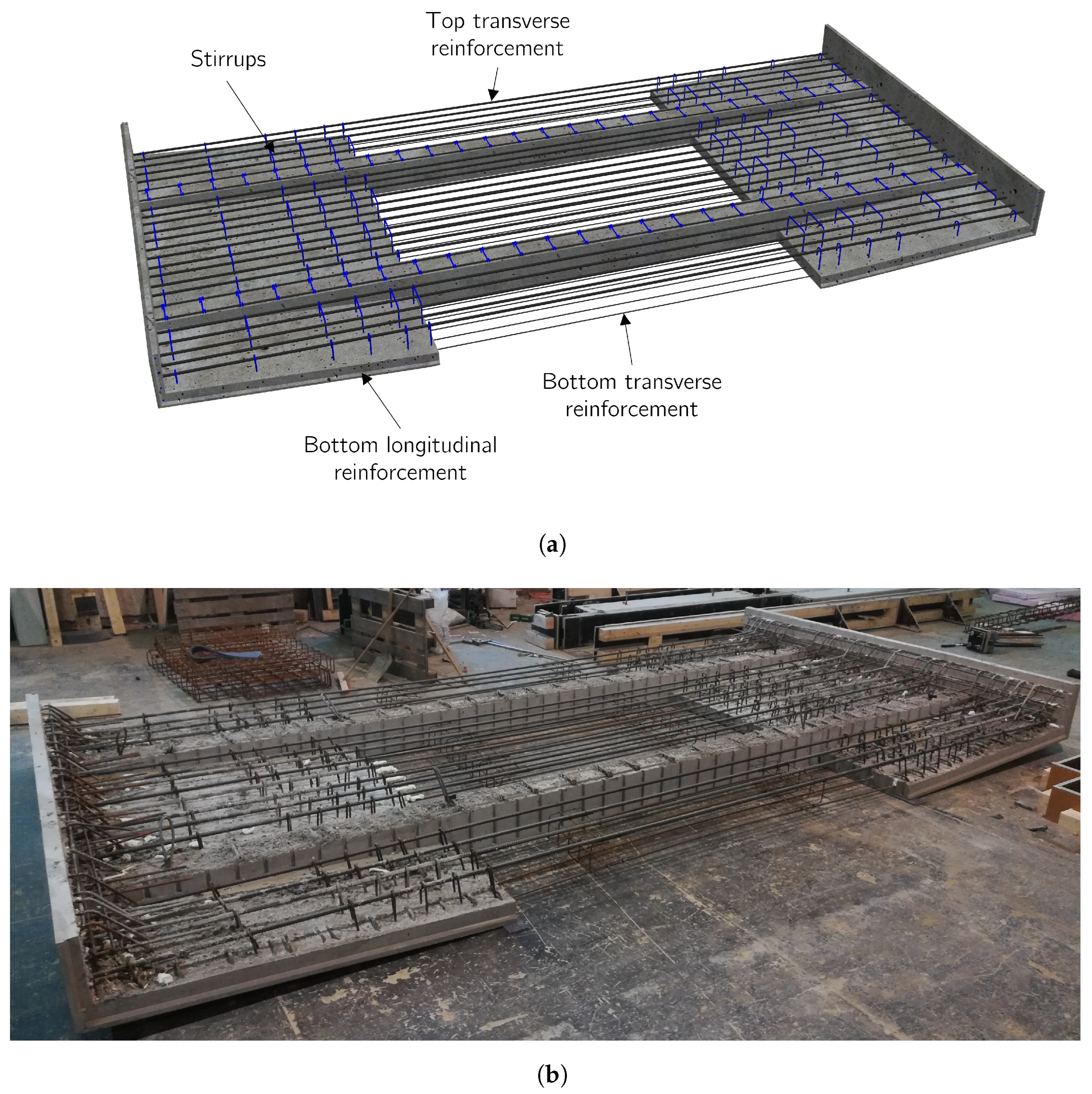
3.1. Innovative Precast Deck Slab Element

To meet the requirements for the precast deck slab element mentioned above, thin plates (80–100 mm) are connected with one, or preferably two, reinforced concrete (RC) cross-beams (Figure 6). The cross-beams are responsible for transferring the loads, which occur during the construction of the slab, in the transverse direction of the bridge structure. Thus, they must carry the dead load of the precast element, the top layer of CIP concrete, and a construction crew that can use the element as a working platform. Ideally, the length of the deck slab corresponds to the width of the bridge in the final state. At the edges, upstands are arranged and create a lateral formwork for the top layer of CIP concrete. The height of the upstands is equal to the height of the finished deck slab at the cantilever end. For wide bridges with many lanes or several tracks, the deck slab element can also be split longitudinally. Then, the element is subdivided into cantilever slab elements and span slab elements.
The layer of concrete above the cross-beam should not exceed 100 mm, therewith the cross-beams still have a sufficient effective depth d. This thickness of the layer of concrete above the cross-beams comprises the space required for (a) sufficient concrete cover, (b) upper longitudinal reinforcements, and (c) a height by which the top reinforcement protrudes from the cross-beam. This detail of a protruding bending reinforcement is presented in Section 3.2. In Section 5.1, experimental investigations regarding this detail are shown.
To obtain a proper bond with the top layer of CIP concrete, the top surface of the plates must be roughened. In addition, reinforcements projecting from the thin plates also serve as shear reinforcement in the finished deck slab.

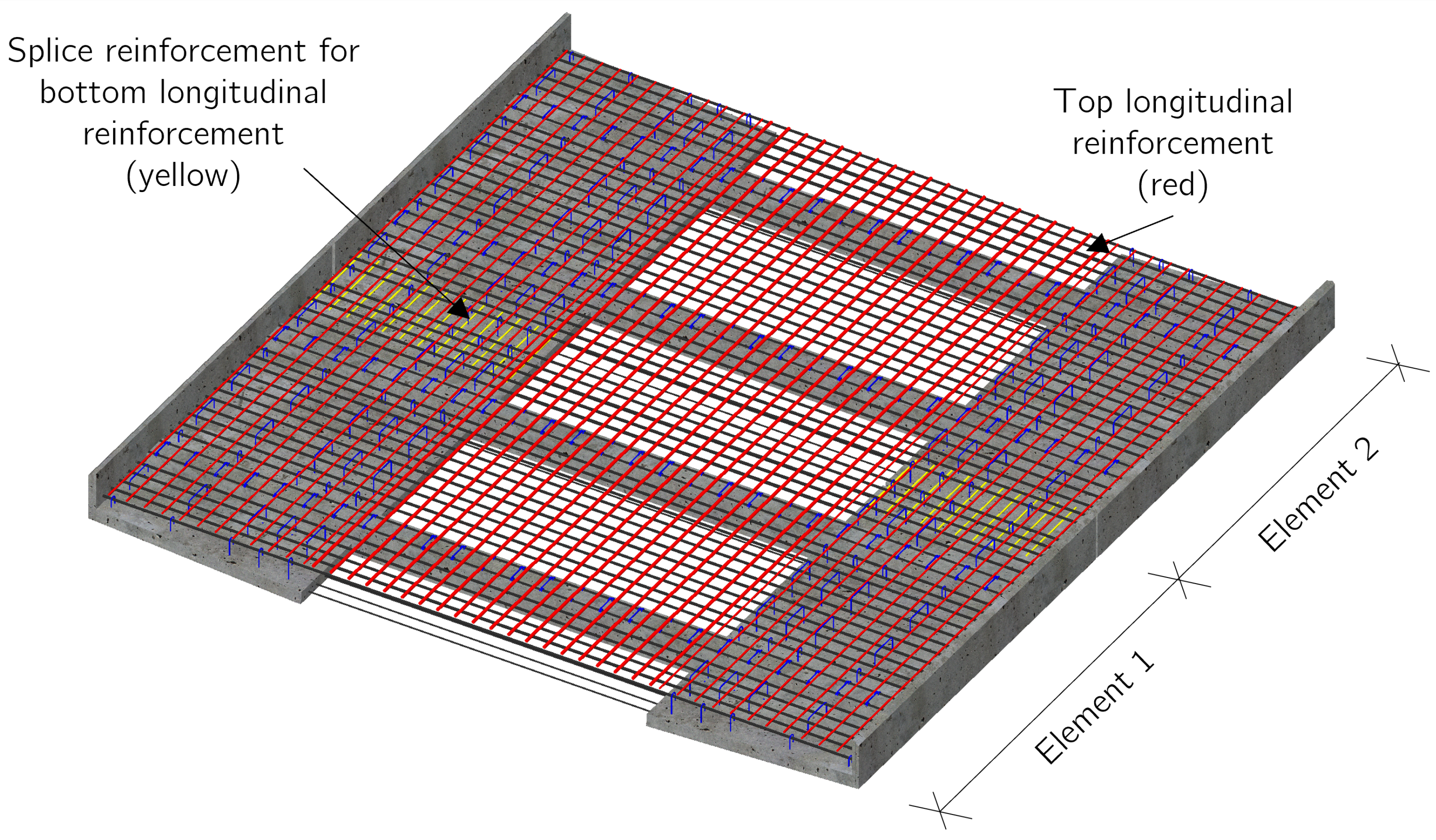
3.2. Reinforcement Layout

The reinforcement layout is similar to a deck slab made from CIP concrete. During the conceptual design of the deck slab elements, the aim was that as much reinforcement as possible should already be integrated in the precast element, to achieve the fastest possible construction progress on-site, as can be seen in Figure 7. On-site placement of reinforcement is thus limited.
The reinforcement that is already present in the elements includes (a) the bottom transverse reinforcement, (b) the top transverse reinforcement, (c) the bottom longitudinal reinforcement and (d) the shear reinforcement (Figure 7). Only the splice reinforcements for the bottom longitudinal reinforcement, which run over the transverse joints, and the top longitudinal reinforcements must be placed on-site (Figure 8). Since it is helpful to place only the upper longitudinal reinforcements at the construction site, as they reach over several elements, the sequence of the upper longitudinal reinforcement and the upper transverse reinforcement is reversed in comparison to the reinforcement layout of usual CIP slabs.
To minimize the reinforcement placement at the construction site, the top transverse reinforcement is already installed in the precast deck slab element. Therefore, only the top longitudinal reinforcement must be placed on top of the transverse reinforcement. This new reinforcement layout leads to swift construction progress. Nevertheless, the swapping of the top two layers of the reinforcement has a small negative effect on the inner lever arm d for transverse bending.
The reinforcement of the cross-beams should be designed in such a way that the cross-beams are capable of carrying the dead load of the precast deck slab element and a top layer of CIP concrete. To maximize the effective depth d for transverse bending, the reinforcement protrudes from the beam by half its diameter. This protruding reinforcement is anchored into the concrete using additional loops. Another advantage is that the protruding reinforcement serves as a spacer and support for the upper longitudinal reinforcement that is placed on-site. Moreover, the reinforcement layout of the cross-beams forms a rough surface, which is advantageous for the bond between the precast element and the CIP concrete.

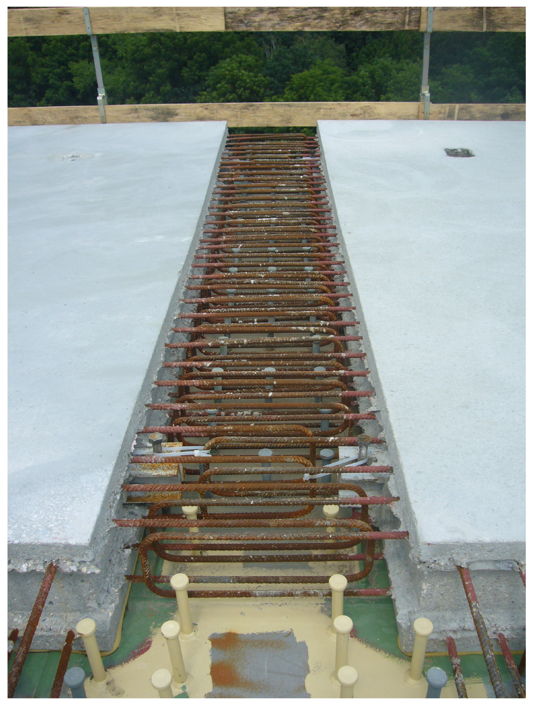
3.3. Longitudinal and Transverse Joint Details

Several implementation options have been developed for the bearing and sealing detail of the precast elements [19]. It is important that precast deck slab elements rest evenly on all bearing points and that a seal is created between the longitudinal steel structure and the precast deck slab elements. Sealing is important to prevent the top layer of fresh CIP concrete from leaking through (a) the longitudinal joint between the steel structure and the precast deck slab elements, and (b) the transverse joint between two precast deck slab elements.
The preferred option for implementation of the longitudinal joint is drawn on the left side in Figure 9. For more clarity, the shear studs and the reinforcement protruding from the deck slab element are not shown. The figure shows a cross-section through the longitudinal steel girder and the deck slab element in the area of a cross-beam. The cross-beams of the deck slab element are slightly lower in the area of the steel girders and are placed on mounting bearings with the same width as the cross-beams. Sealing is achieved by means of concrete sealing elements that are added into place after the deck slab elements have been placed. Due to the sealing component, which preferably has the same strength properties as the cured top layer of CIP concrete, the effective depth d in the final state of the bridge is not reduced for transverse bending. If the bridge has a transverse slope, this can be adjusted with mounting bearings of different heights or setting screws installed in the cross-beams. The longitudinal steel girders are then installed at different heights if there is more than one steel girder.
On the right side of Figure 9, a longitudinal section is shown in the area where two deck slab elements meet. To create a horizontal bottom seal, an angle made of plastic or other durable material is inserted into the joint.

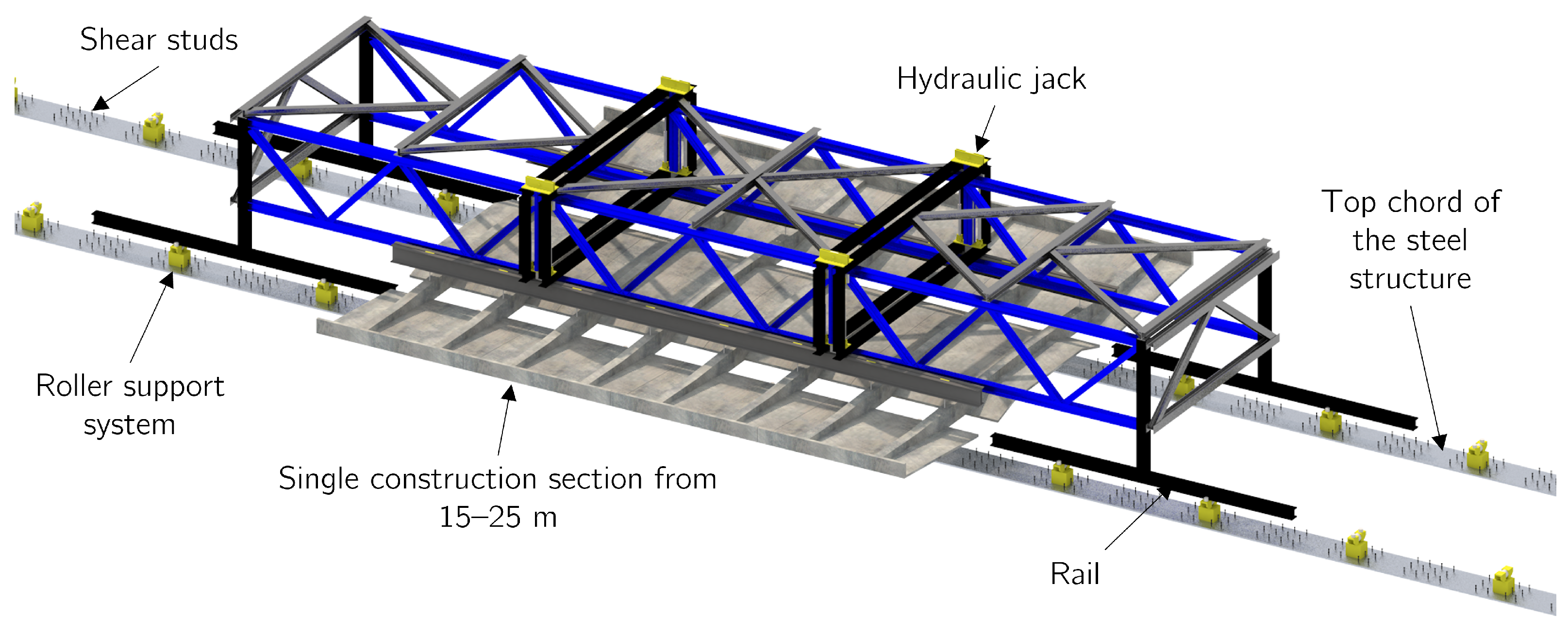
3.4. Transportation Carriage

A transportation carriage (Figure 10) for the placement of the precast deck slab elements will be useful in cases when crane assembly of the elements is not possible, e.g., for topographical reasons.
Instead of a direct support of the cantilevers in transverse direction by a formwork carriage (Figure 1b), the load transfer is carried out via the transportation carriage in the longitudinal direction. The reversal of the load transfer direction is based on the fact that the slab elements protrude outwards in the transverse direction and, causing collisions with transverse frames of common solutions. Therefore, the transportation carriage consists of two longitudinal trusses (shown in blue in Figure 10), which are connected to each other by a wind brace (shown in gray in Figure 10). The rails, frame columns, and cross frames for bearing the loads of the deck slab elements are shown in black in Figure 10. In comparison to a formwork carriage, the transportation carriage has to bear only the dead weight of the precast elements and not all of the CIP concrete for the construction section. Therefore, it is assumed that less steel needs to be used for the construction of the transportation carriage.
A total of eight hydraulic cylinders with long stroke lengths synchronized to each other are mounted on the cross frames. They are responsible for lifting and lowering the deck slab elements. To avoid the deck slab elements from being on the oil circuit during the transport process, they are mounted with bolts at the cross frames. A recoverable roller support system (shown in yellow in Figure 10) is attached to the upper chord of the steel structure, upon which the transportation carriage can be moved.
In order to assemble the deck slab elements on the transportation carriage, the already completed steel structure is connected to an assembly area behind one of the two abutments. At the assembly area, the deck slab elements are prepared so that the transportation carriage can be moved over them and pick them up.

3.5. Proposals for the Construction

Since, in bridge construction, the distribution of internal stresses due to dead weight in the state directly before opening the bridge for traffic is significantly related to the construction method [20], a well-thought-out construction schedule is essential for an economical and durable design. In addition, the time factor is largely determined by the construction method.
In most cases, the entire steel superstructure is built first (e.g., incremental launching, erection with cranes, or cantilever erection). After completion of the steel superstructure, the concrete deck slab can be built. For multi-span bridges, the concrete slab is exposed not only to compressive stresses but also to tensile stresses. Since the entire slab can rarely be cast in one working step, concreting sections must be defined. The concreting sections are usually defined so that the areas that are concreted first are those where sagging moments occur due to the dead weight [21]. After the CIP concrete of these construction sections is cured, the areas over the supports are cast. This defined sequence prevents the slab from cracking in the areas over the supports due to the dead weight. This so called “step-back method” is also applicable to the construction method presented in this paper.
After placing the precast deck slab elements on the steel structure, either with a transportation carriage or cranes, the application of the CIP concrete controls which areas are first bonded to the steel structure. It is also possible to first apply a thin layer, as thick as the bottom plates of the deck slab elements ( t = 80–100 mm), to create a partial bond with the precast elements and the steel structure. This method of construction requires double-headed shear studs or shear studs of different heights. Due to the partial bond, the concrete contributes to the load transfer and absorbs stresses in the longitudinal direction of the bridge, when the second CIP concrete layer is applied. Saving opportunities of the sheet thicknesses of the upper chord of the steel girder considering a partial bond have already been described in [10,22].

4. Discussion

4.1. Comparison of the New Construction Method with Conventional Variants

Compared with conventional variants, presented in Section 1.1, the use of deck slab elements (Figure 6) enables a significant acceleration of the construction process on-site. Figure 11 shows a simplified construction process of building the deck slab using (a) a formwork carriage and (b) the new modular construction method presented. Since there are different general conditions for each bridge project, the individual work steps are not provided with a time component.
Instead of casting one slab section (15–25 m) in a week by using a formwork carriage (according to the benchmark values in [23]), it is estimated that up to two slab sections can be produced in one day using the new construction method. For the transportation carriage specially designed for the transport of the precast elements, there is no need to wait until the concrete of the construction section reaches a sufficient compressive strength. After a construction section has been installed, the transportation carriage can be moved back to the assembly area to pick up the next precast elements. The elements are able to carry their own weight and an additional concrete layer without any temporary supporting structure. Therefore, the placing of the additional reinforcement at the joints between the sections and casting the top layer of concrete is independent of the installation of the deck slab elements as can be seen in Figure 11. Work steps can thus run in parallel.
Since the deck slab elements serve as formwork for the top layer of CIP concrete, no time-consuming application of formworks needs to be carried out for the deck slab. The thin concrete plates, which are stiffened by cross-beams serve as a formwork and can be fully taken into account in the structural analysis.
As the majority of the reinforcement required for the deck slab is already placed in the precast element, there is no need to carry out laborious reinforcement placing work on the construction site. Only the splice and the top longitudinal reinforcement have to placed on-site. In case of ordinary construction methods, all reinforcement works have to be carried out on-site.
Compared with the production time for conventional methods (approximately one construction section per week), the new construction method presented here is significantly faster and meets the requirements of all parties involved in the project.

4.2. Application Boundaries

The dimensions of the precast deck slab elements are primarily restricted by the maximum transport dimensions and transport weights in the respective country. For regular transport in most countries of the European Union, the maximum width is 2.55 m, the maximum height is 4.0 m, and the maximum length of the semitrailer is 16.5 m [11]. The permissible transport weight per semitrailer is approx. 24 t. If special transport is authorized, these dimensions and the weight can be exceeded.
For most new road bridge constructions, the owner requires that a separate superstructure has to be built for each directional carriageway for maintenance reasons. In case of major repair works, one bridge superstructure can be closed and all traffic can be diverted to the other superstructure (4 + 0 traffic routing) [2]. Applying the outlined maintenance strategy results in maximum widths of bridge decks of approx. 15 m for highways. In the case of railway bridges with two tracks, the value of approx. 15 m is also not exceeded. Such a bridge width can very well be constructed with a sufficient steel structure according to the span length and deck slab elements, as shown in Figure 6.
Further attention must be paid to the deformation of the deck slab elements after placing of the CIP concrete and the additional dead load. Therefore, the length of the cantilevers (cross-beams) should not exceed the value of 3.5 m. Elevations of the deck slab element can be produced in the precast plant up to a certain limit.

5. Experimental Investigations

In this section, experimental investigations regarding the innovative deck slab element are shown. Figure 12 shows a deck slab element with different-colored parts representing the investigated regions. In a first test series, experiments on the transverse load-bearing behavior were performed on specimens of cross-beams (red in Figure 12) produced without a top concrete layer (construction state). For the longitudinal behavior of the finished deck slab, in a second test series, experimental investigations were conducted on imaginarily cut out parts of the finished deck slab (blue in Figure 12).

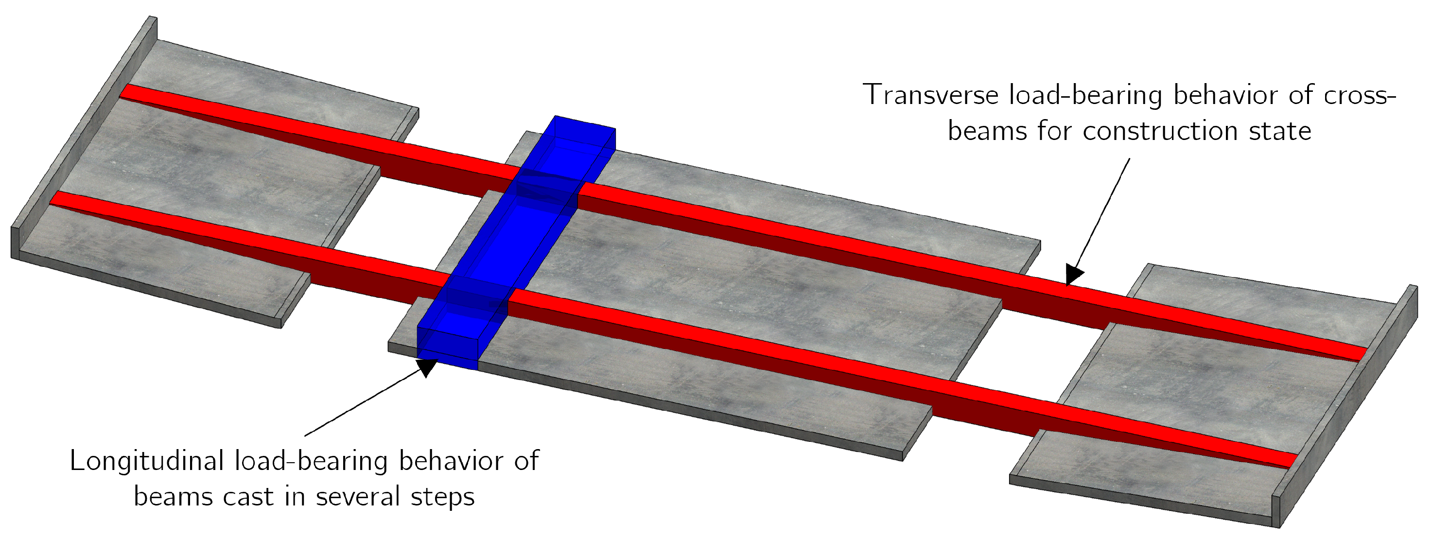
5.1. Transverse Load-Bearing Behavior of Cross-Beams for Construction State

In order to verify the operation principle of the introduced reinforcement layout of the cross-beams from the precast deck slab elements in the construction phase, experimental investigations were conducted. A total of four tests were performed on cantilevers. The parameters investigated were (a) the spacing s of the additional loops, which project from the upper surface of the cross-beam, and (b) their anchorage length l b . The additional loops form a substitution for the concrete cover, which is, among other things, responsible for the transfer of bond stresses.
The effects of reduced or no concrete cover on the bond strength have already been investigated in a number of pull-out and bending tests with and without a confining reinforcement [24,25]. Due to the reduction in the concrete cover, the longitudinal reinforcement can no longer be brought to a state of yielding, as premature splitting failure occurs before. Pull-out tests on eccentric half-joint cantilever specimens were conducted by Mak and Lees [26] to investigate how bond conditions are affected by reductions in concrete cover. Several tests have been carried out in which the concrete cover was gradually reduced until the rebar was only half-embedded in the concrete. Transverse reinforcement in the form of links was present in all specimens. All tests with half-embedded rebars resulted in a low pull-out resistance compared to the tests with appropriate concrete cover. No additional loops above the protruding reinforcement were provided.

5.1.1. Specimens and Test Set-Up

Two beams were produced by Alfred Trepka GmbH (Ober-Grafendorf, Austria), each of which was tested at both ends, resulting in a total of four bending tests. The height h and width b of the members were 430 and 220 mm, respectively. The length l of each beam was 8000 mm. Each of the four tests was labeled with an identifying code. The first four characters describe the loop spacing in mm, either 100 or 200 mm (S100/S200). The following four to five characters correspond to the anchorage length of the loops, either 95 or 295 mm (AL95/AL295). The test set-up is shown in Figure 13. The distance between the support and the loading point of the cantilever was a v = 3000 mm. Uplifting was prevented by two tension rods at the opposite support.
An illustration of the cross-section above the support is shown in Figure 14. The longitudinal reinforcement and the stirrups were identical in both beams. The top longitudinal reinforcement consisted of four continuous bars of Ø26 mm. The four bars were combined into two-bar bundles. The lower bar was fully embedded in concrete, and half of the diameter of the second bar directly above protruded from the upper edge of the member. The bottom longitudinal reinforcement consisted of four continuous bars of Ø20 mm. These bottom bars were enclosed by the shear reinforcement Ø10 mm, which consisted of two-legged stirrups, equally spaced at a distance of 100 mm. The shear reinforcement of Ø10 mm was installed at a distance of 100 mm and consisted of two-legged stirrups. The stirrups were led out of the beam at the top and bent around the upper longitudinal reinforcement, resulting in two overlapping legs at the top of the bar. The overlapping distance was 60 mm. In order to exert as little influence as possible on the additional loops, the legs of the stirrups were not closed.
The reinforcement was designed in such a way that a flexural failure in the region of the support is ensured. In this way, it was possible to investigate whether the protruding reinforcement can be loaded to the yield stress. Therefore, sufficient shear reinforcement was provided and a high shear-to-span ratio λ = 7.19 was chosen. A high shear-to-span ratio λ is equivalent to an increase in the acting bending moment with a constant shear force and avoids direct compression struts leading into the support.
According to Kani [27], this ratio has a remarkable influence on the shear capacity. It can also be considered as a bending-moment-to-shear force ratio. Through experimental studies [27], the range between 2.0 λ 4.0 was found to be particularly at risk for shear failure for beams without sufficient shear reinforcement.

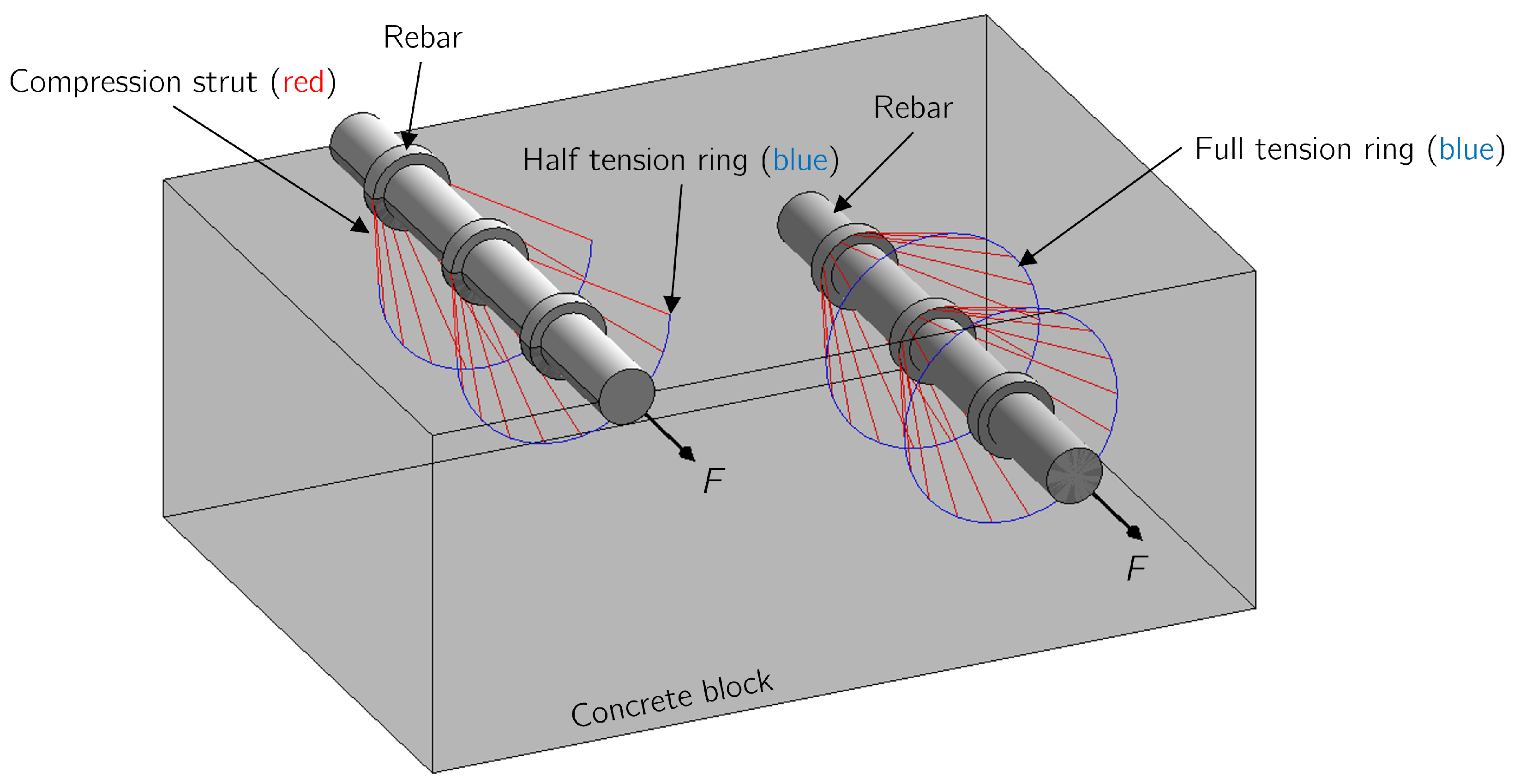
5.1.2. Theoretical Considerations Regarding the Mechanical Operating Principle of the Additional Loops

The mechanical background of bonding between concrete and reinforcement has already been described in great detail [28,29]. The mechanical model consists of three-dimensional tension rings and compression struts, which are in equilibrium. The compression struts, emanating radially from the ribs of the rebar, form a tension ring running radially around the reinforcing bar. In the instance of unconfined concrete, these tensile stresses must be absorbed by the concrete alone. If the ultimate tensile stress resistance of the plain concrete is exceeded, this leads to sudden and brittle premature splitting failure with associated spalling of the concrete cover, if any. The main parameters that have an influence on the bond failure mechanism are (a) the bond conditions, (b) the compressive strength of the concrete, (c) the diameter of the rebar, (d) the concrete cover, and (e) the confining reinforcement [30].
The mechanical operating principle of half- and full-embedded rebars is drawn in Figure 15. Assuming that only one layer of the rebar is half-embedded in concrete, only half a tension ring can be formed, which is in equilibrium with the compression struts. As a result, only half of the surface is available for transmitting bond stresses. To utilize the tensile strength of the rebar, higher bond stresses must be transferred due to the smaller contact surface between the rebar and the concrete. The higher bond stresses result in higher principal tensile stresses that must be absorbed by the concrete. The additional loops placed around the half-embedded rebar act as a confining reinforcement and can absorb these higher principal tensile stresses. Moreover, the additional loops are responsible for securing the position of the half-embedded rebar due to friction.

5.1.3. Material Properties

The concrete with a maximum aggregate size of 22 mm was designed to have a target compressive strength f cm of 48 N/mm 2 (C40/50 acc. to Eurocode 2 [31]). The resulting water–cement ratio w / c was 0.48, and class CEM I cement was used. The detailed composition of the concrete is shown in Table 1. The material properties are described in Table 2. Compression tests on three cubes ( a = 150 mm) were used to determine the mean cube compressive strength f cm , cube . Based on f cm , cube , the average cylindrical compressive strength f cm , cyl (acc. to Goller [32]), the average tensile strength f ctm (acc. to Eurocode 2 [31]) and the average modulus of elasticity E cm (acc. to Eurocode 2 [31]) were calculated.
In total, two tensile tests were performed on Ø26 mm reinforcing bars that were installed in the specimens. The mean values of the results are shown in Table 3.

5.1.4. Measurements

The applied loads were simultaneously measured via load cells mounted at the hollow piston jacks (Eberspächer GmbH, Esslingen, Germany) and load cells (HBM GmbH, Telgte, Germany) at each support. The uplift forces were calculated based on strain gauge measurements on the tension rods. To quantify the contribution of the protruding reinforcement during the tests, two strain gauges (HBM GmbH) at each protruding bar, right above the supporting area, were applied. Surface deformations during testing were measured using digital image correlation (Aramis 4M, resolution 2352/1728 pixels, GOM, measurement frequency 1/4 Hz). Linear variable differential transformers (LVDTs) were positioned underneath the specimens to measure the deflections during the tests (Solartron BS50 100 mm (Solartron Metrology, West Sussex, UK), maximum relative error of indication < ±1%, measurement frequency 5 Hz). In addition, concrete strain gauges (HBM GmbH) were applied in the compression zone above the support areas. These were located 50 mm above the bottom edge of the beam.

5.1.5. Test Results and Interpretation

Figure 16 shows two diagrams obtained from the experimental investigations. Figure 16a shows the load–deflection relationships for all four tests. The applied load is plotted against the relative deflection (LVDT 6-LVDT 2 in Figure 13) at the cantilever end. Figure 16b shows the bending moment–curvature relationships. The curvature κ right above the support can be calculated with the help of the strain gauges placed both on the protruding reinforcement and the lateral surface in the compression zone of the beam.
In each test, the force was increased in 20 kN increments until a yield plateau was observed in the load deflection curve. After the bending reinforcement was in the state of yielding for a short time, the tests were stopped. Only during the first test a) S100AL95, the load application was prematurely terminated because of concerns damaging the other side of the beam for the second test. This is why the associated load deflection path stops abruptly. Since the second attempt was seen to have no destructive effect on the other side, the first attempt was loaded to failure on the second beam.
In addition, in Figure 16b, the bending moment–curvature path is plotted, which was generated using the interactive non-linear cross-section analysis software INCA2 Version 3.0 [33]. That path was generated using the material properties shown in Section 5.1.3. Comparing the generated moment–curvature path with the test results, it can be clearly seen that in tests b)–d), the ultimate limit state for bending was reached. In test a) S100AL95, the ultimate limit state for bending would also have been reached if the beam had been further loaded.
In Figure 17, the stress in the protruding bending reinforcement σ s is plotted against the applied load F exp . From the test results shown in Table 3, a bilinear material model was derived to calculate the reinforcement stresses from the measured strains. The diagrams in Figure 17a–d also confirm that the yielding point of the protruding reinforcement has been reached during the tests.
Figure 18 shows the crack pattern of all four tests at maximum load F max above the support. As can be seen, an ordinary bending crack pattern was obtained in each test.
From these results, it can be concluded that the transfer of bond stresses between the protruding bending reinforcement and the concrete worked properly with the help of the additional loop reinforcement. The influence of the selected parameters (a) the spacing s and (b) the anchorage length l b of the additional loops did not have a significant effect on the results, as can be seen in Figure 16. Even with the configuration that has the lowest loop reinforcement ratio ( s = 200 mm; l b = 95 mm), the flexural reinforcement could be fully utilized.
A detailed structural analysis according to Eurocode 2 [31] for the construction stages of the deck slab for a fictitious project is presented in [34]. In that analysis, the cross-beam of the deck slab element must withstand a design bending moment of 120 kNm during the erection of the deck slab including all safety factors. In this case, it is a 3.10 m long cantilever on which the dead weight of the deck slab element, the top concrete layer and construction traffic loads were applied. The mean bending moment resistance (S100AL95, S200AL95 and S200AL295) was 465 kNm.
The prerequisite for this reinforcement concept to work is impeccable production in the precast plant. The additional loops must be in contact with the protruding reinforcement such that there is no gap between them. The dimensional accuracy of the reinforcement cage and, in particular, the geometric position of the upper transverse reinforcement in the formwork are of high importance. It is recommended that additional loops are placed at each position of the shear reinforcement of the cross-beams. The additional loops should be anchored into the cross beam with their full anchorage length, according to its diameter.

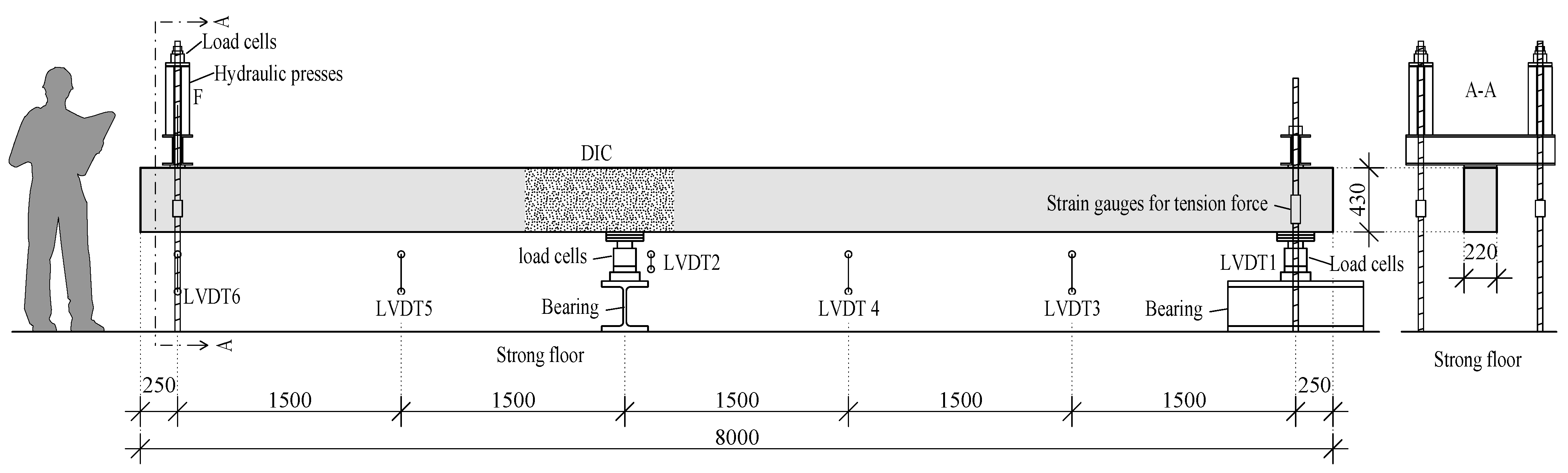
5.2. Longitudinal Load-Bearing Behavior of Beams Cast in Several Steps

In order to investigate the effects on the flexural capacity of a beam cast in several steps, experimental investigations were conducted. Further, the sufficient embedment length of the shear reinforcement in the thin bottom plate ( h BP = 70 mm) of the specimens was investigated. A total of four tests were performed on cantilevers. The two tested beams represent an imaginary part of the finished deck slab cut out lengthwise (Figure 12). The parameters investigated were (a) the reinforcement layout and (b) the height h CB of the cross-beam stubs. A common reinforcement layout was compared to the layout that was introduced in Section 3.2, where the top longitudinal reinforcement of the cross-beam is located in the first layer from the top.

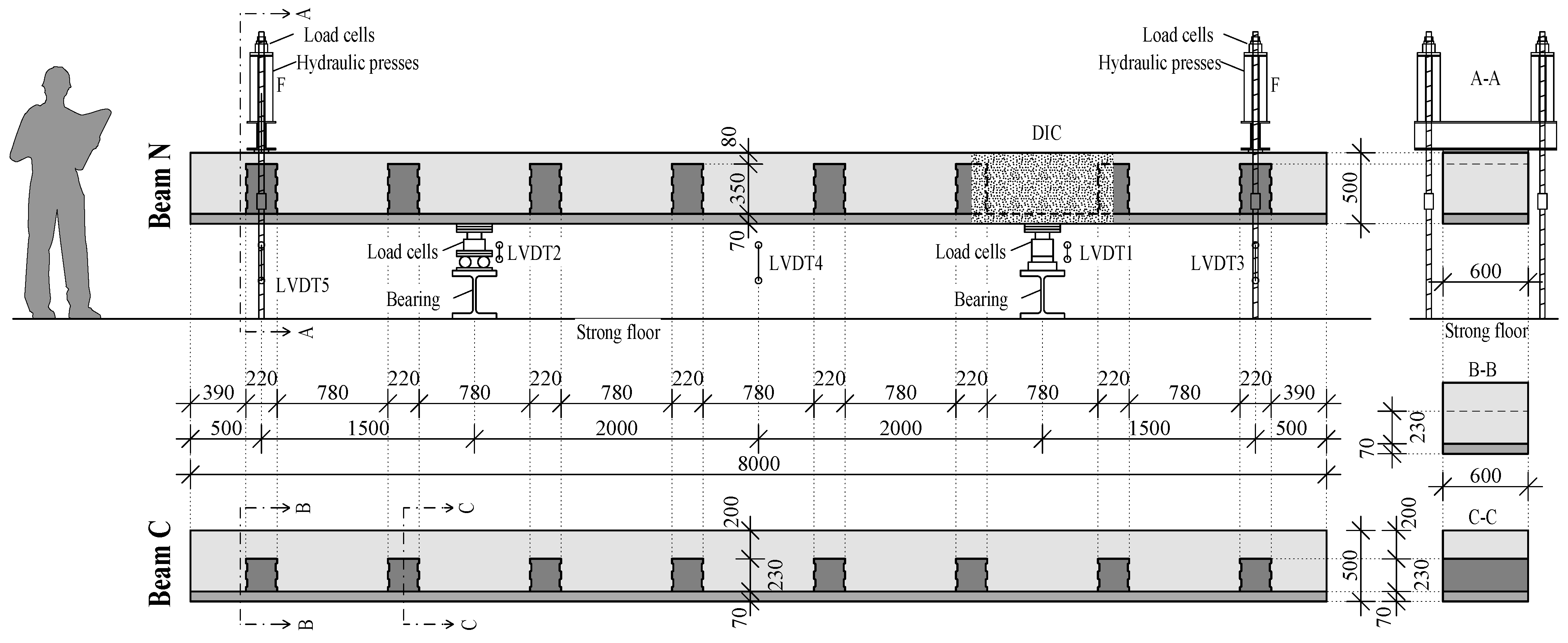
5.2.1. Specimens and Test Set-Up

Two tests were simultaneously performed on one beam, as can be seen in Figure 19. The beams were cast in a total of three working steps by Franz Oberndorfer GmbH & Co KG (Gars am Kamp, Austria). First, the bottom plate with a thickness of 70 mm was cast. In the second step, the cross-beam stubs were cast on top of the hardened bottom plate. In the longitudinal direction of the beam, their length was 220 mm. The heights of the cross-beam stubs were 350 mm (beam N) or 230 mm (beam C). In the final step, the top concrete layer was cast. Between each of the casting steps, one day passed. Accordingly, the height of the concrete layer above the cross-beam stubs was 80 mm (beam N) or 200 mm (beam C). This results in a total height h of 500 mm of the two beams. The total width b was 600 mm. The length l of the beams was 8000 mm. In order to obtain a proper bond between the cross-beam stubs and the top layer of concrete, the bottom slab and the top surface of the cross-beam stubs were roughened by raking. In addition, an indented construction joint was created between the lateral surface of the cross-beam stubs and the top layer of concrete, by using trapezoidal strips inside the formwork, according to Eurocode 2 [31].
The shear span-to-effective depth ratios λ = a v / d for beam N and beam C were 3.36 and 3.39, respectively. These values were chosen so that bending–shear failure could occur.

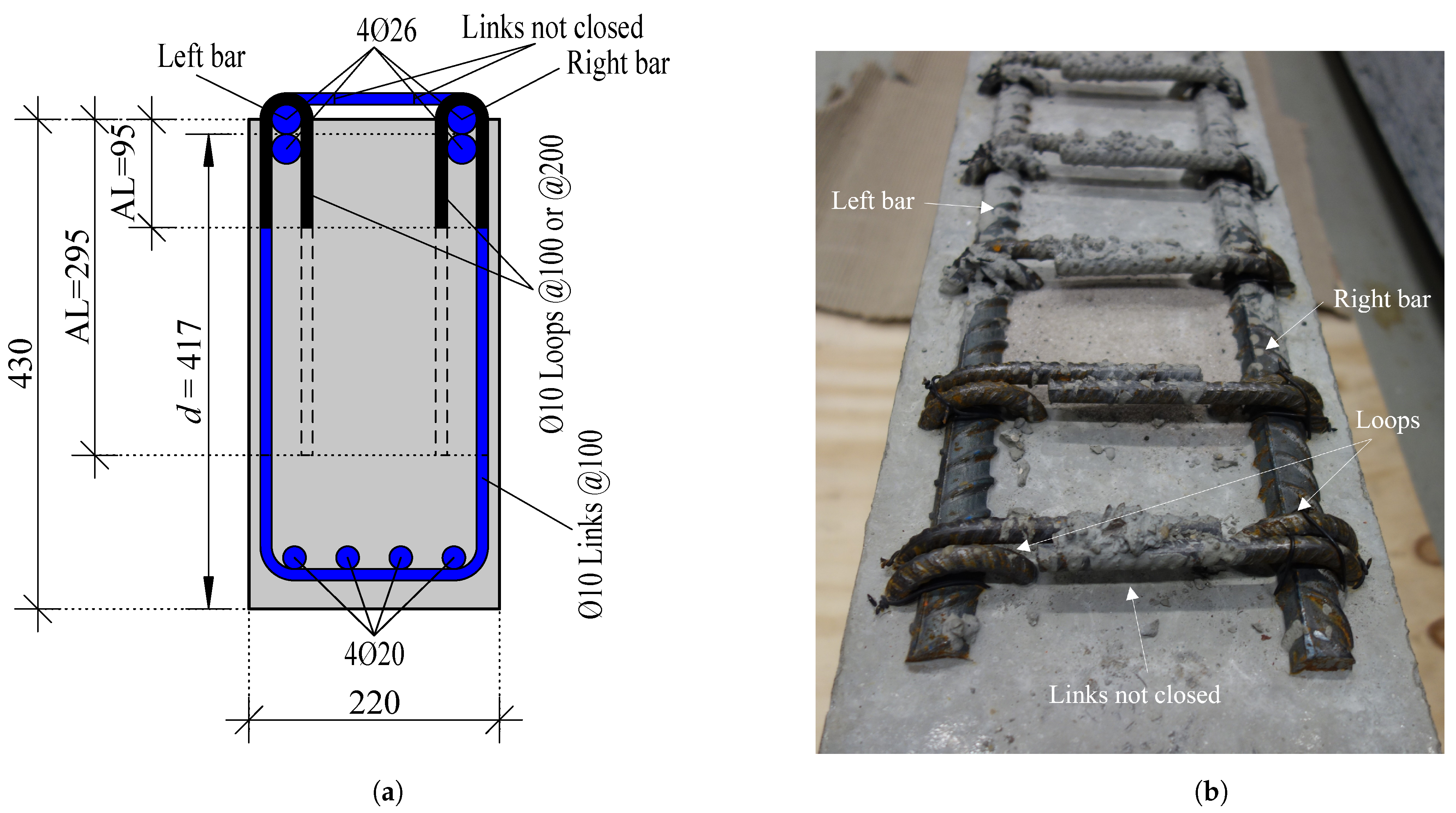
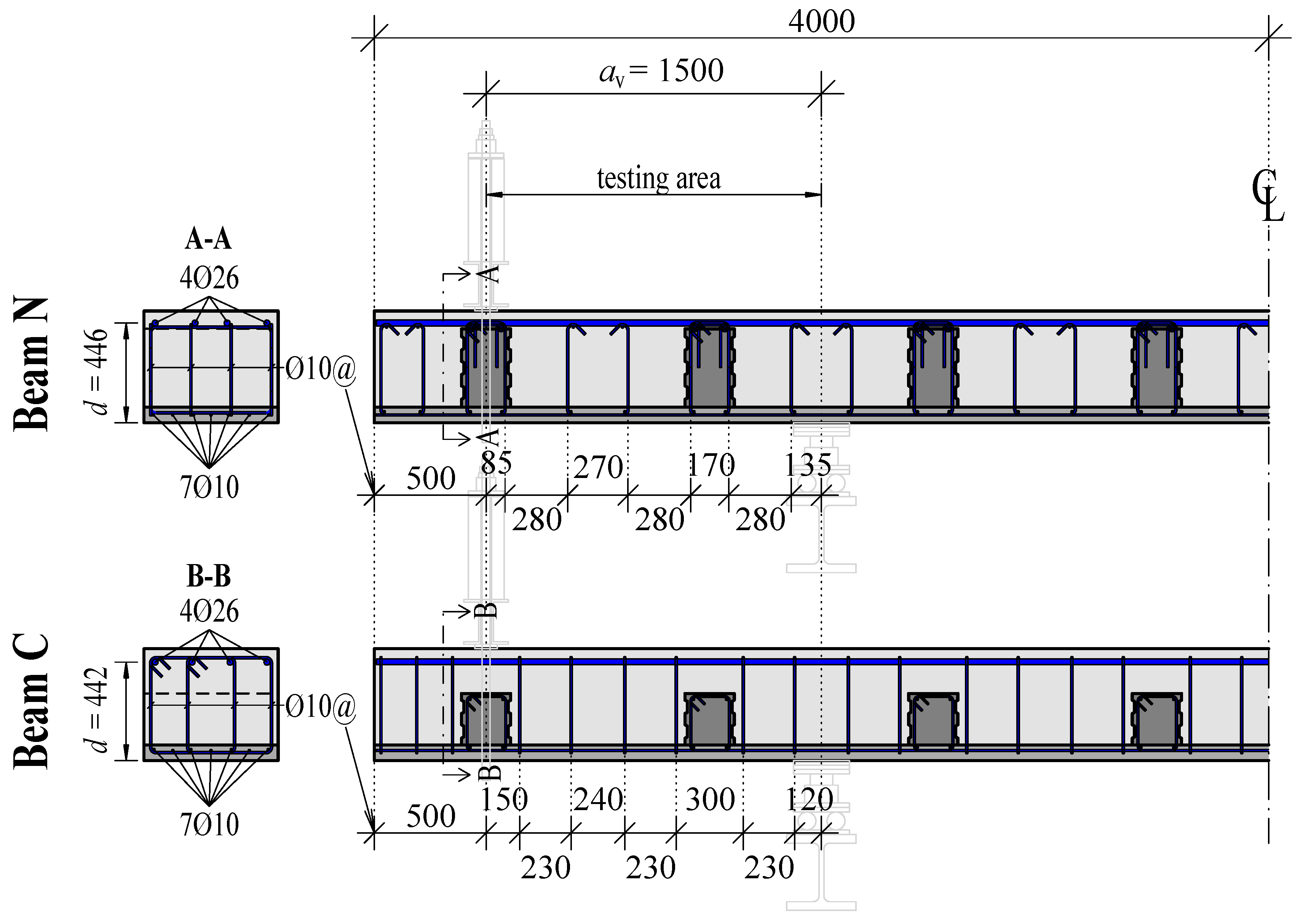
5.2.2. Reinforcement

The different reinforcement layouts for beam N and beam C are shown in Figure 20. The average spacing s avg of the shear reinforcement measured along the longitudinal axis of the member in the test area for beam N and beam C was 256 and 246 mm, respectively. For beam N, the longitudinal bending reinforcement is located above the anchorage of the shear reinforcement, while for beam C, the shear reinforcement was bent around the longitudinal reinforcement bar as usual. In accordance with Eurocode 4 Part 2 [35], the total acting shear force in the longitudinal direction of the composite bridge is usually assigned to the steel cross-section with resistance V pl , a , Rd . Therefore, the interchange of the top two reinforcement layers is not of major importance in steel–concrete composite bridges, as proper anchorage of the stirrups is not required in longitudinal direction. The influence of the proposed reinforcement layout on the structural integrity was investigated by comparison with beam C. Contrary to beam N, the top longitudinal reinforcement was enclosed by the shear reinforcement in beam C.

5.2.3. Material Properties

The concrete with a maximum aggregate size of 22 mm was designed to have a target compressive strength f cm of 48 N/mm 2 (C40/50 acc. to Eurocode 2 [31]). The material properties for the individual components of the beam are shown in Table 4. The material tests described below were carried out for the individual components of the beams (bottom plate, cross-beam stubs, and top layer of concrete). Compression tests on three cubes ( a = 150 mm) were used to determine the mean cube compressive strength f cm , cube . Additionally, tests on three cylinders (Ø = 150 mm, h = 300 mm) were used to detect the mean compressive cylinder strength f cm , cyl . Based on f cm , cyl , the average compressive modulus of elasticity E cm * was calculated according to Eurocode 2 [31]. To determine the mean tensile strength f ctm of the concrete used, splitting tensile tests on three cylinders (Ø = 150 mm, h = 300 mm) were carried out.

5.2.4. Measurements

For testing the longitudinal load-bearing behavior of beams cast in several steps, measurements similar to those described in Section 5.1.4 were performed (see Figure 13). The applied loads were simultaneously measured via load cells directly at the hollow piston jacks and load cells at each support. No special construction for the uplift forces was needed, because two tests were simultaneously performed on one beam. The development of the crack pattern was continuously recorded during the tests using DIC. LVDTs were positioned underneath the specimens to measure the deflections during the tests.

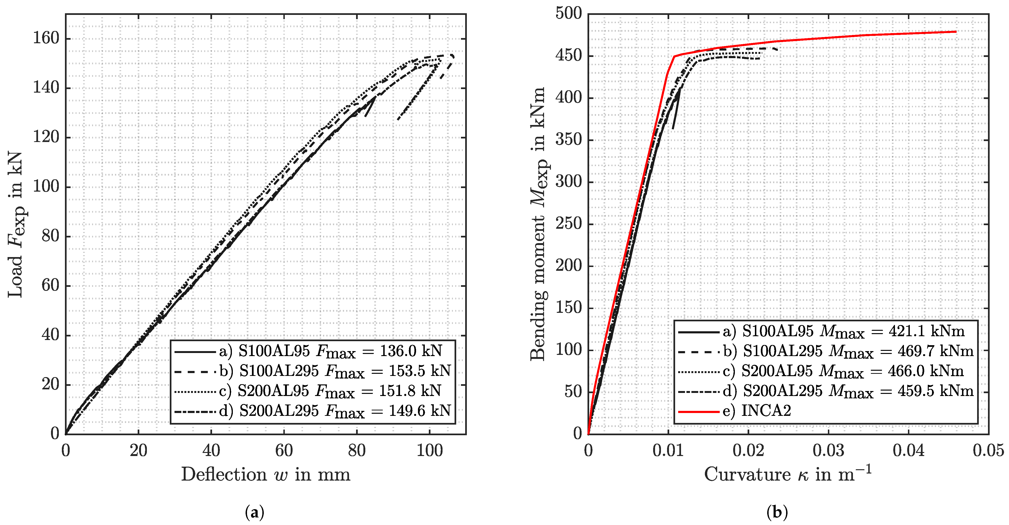
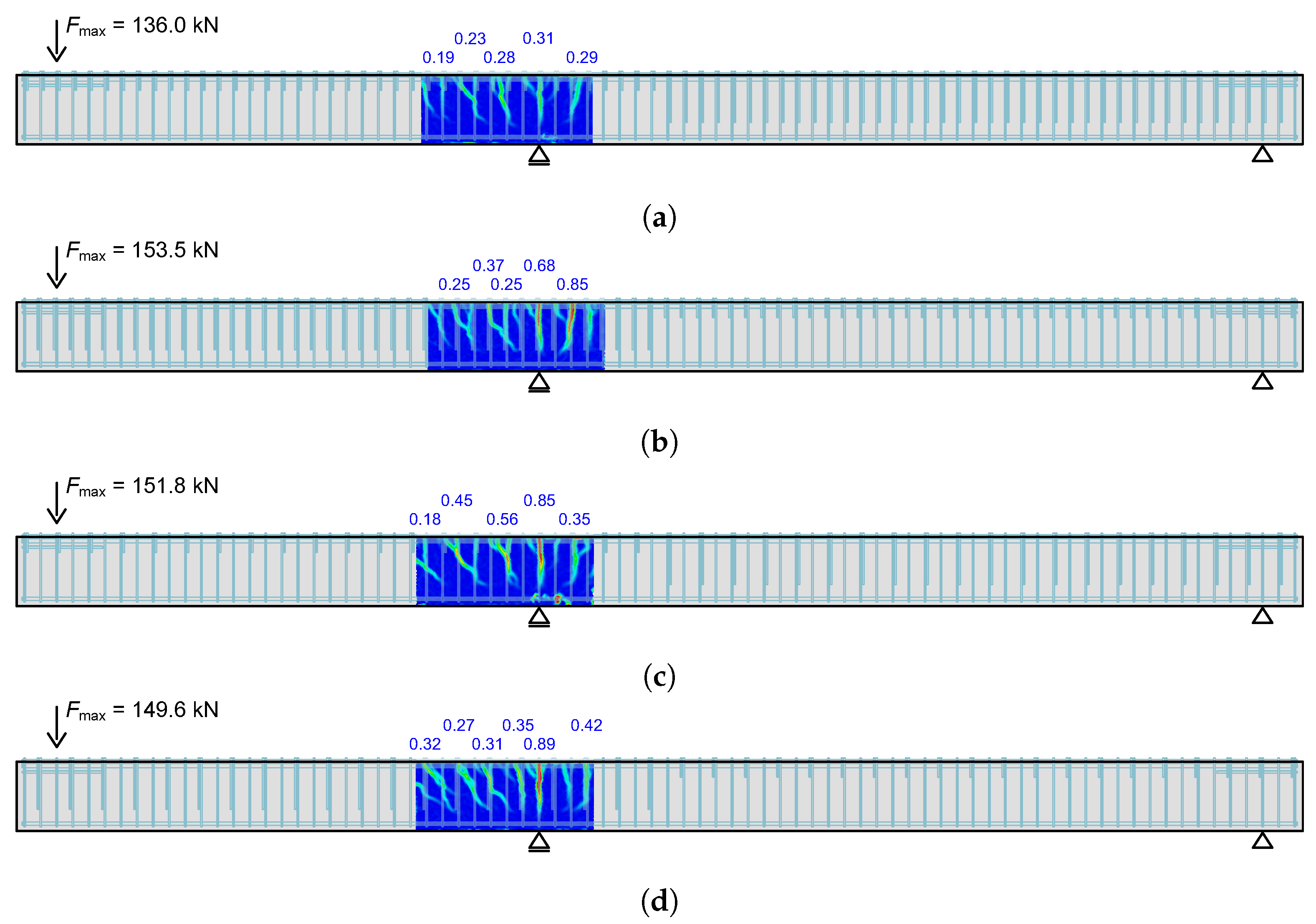
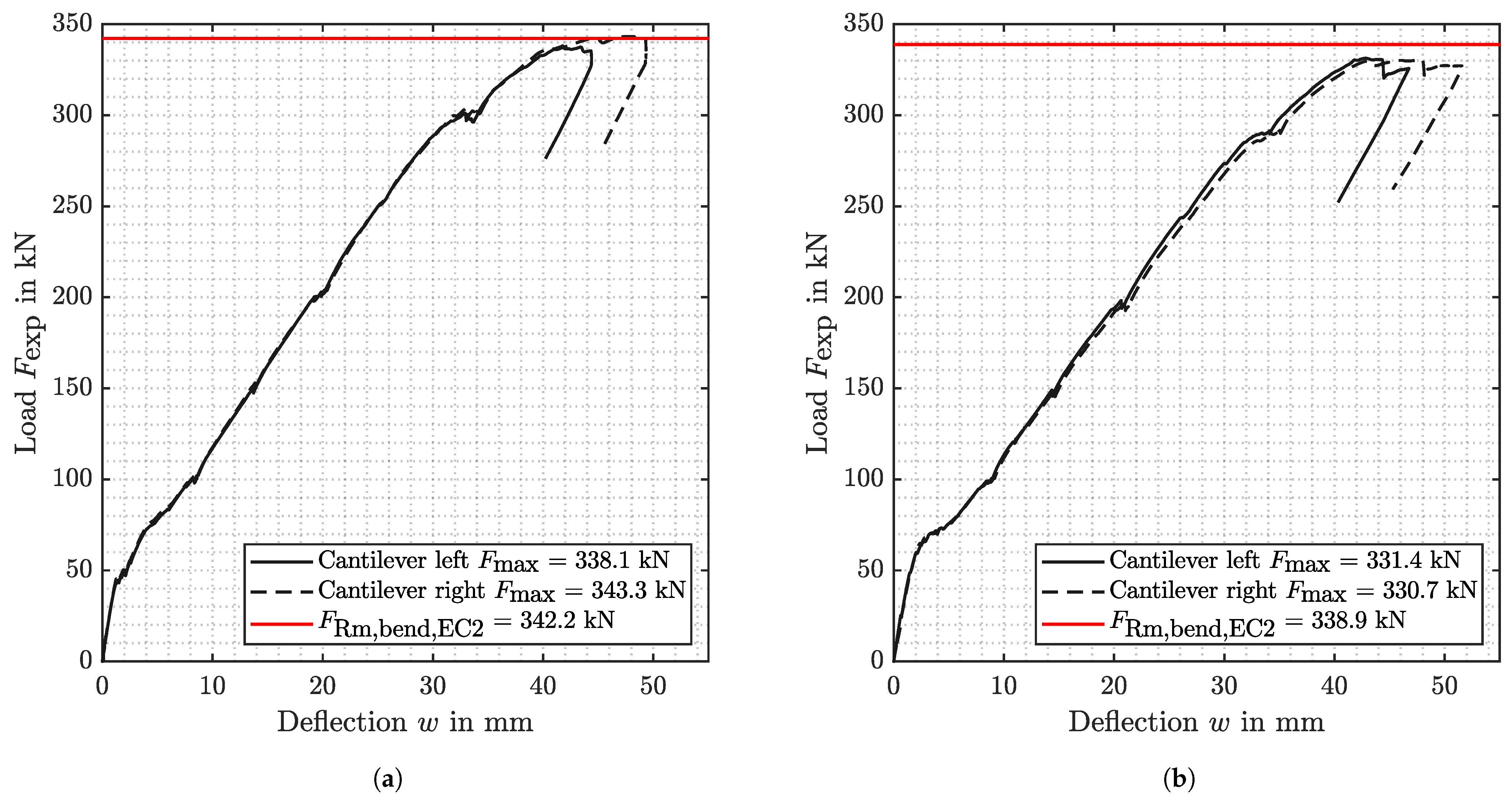
5.2.5. Test Results and Interpretation

In Figure 21, the load–deflection paths for both tested beams N and C are shown. The applied load at the cantlilever ends (left and right) are plotted against the associated relative deflection (calculated from LVDT 3-LVDT 1 or LVDT 5-LVDT2 in Figure 19). The red line shows the flexural capacity for bending [31], calculated with the average values of the measured material properties. The average cylindrical concrete compressive strength f cm , cyl used is composed of the average value of the three components of the beams (bottom plate, cross-beam stubs, and top layer). In this test series, no material tests on the reinforcing steel were performed. Therefore, the properties from Table 2 were assumed.
In both tests, the load at each cantilever end was increased in 50 kN increments until a yield plateau was observed in the load–deflection paths. After no more load increase could be achieved, the tests were terminated. According the pronounced yielding plateau visible in load–deflection curves, flexural failure was attested as failure cause in all four tests.
Figure 22 shows the crack pattern at maximum load F max for beam N and beam C.
The embedment length of the stirrups in the thin bottom plates ( t = 70 mm) was sufficient in all four tests. Due to the vertical force component of the compression strut, tearing of the stirrups cannot occur.

6. Summary and Conclusions

Following advantages of the new construction method can be listed:
  • A significant acceleration of the construction process on-site is achieved by using the developed deck slab elements in combination with the newly designed transportation carriage or crane assembly.
  • Since the deck slab elements can carry their own weight and do not require support during pouring and curing of the CIP concrete, the reinforcement work and concreting of the CIP concrete layer are independent of the installation of the deck slab element.
  • No laborious reinforcement laying operations have to be carried out at the construction site, since the majority of the reinforcement is already placed in the precast deck slab elements.
  • The combination of the precast deck slab elements and a continuous top layer of CIP concrete produces deck slabs with the same quality as slabs produced with conventional methods. There is no joint that extends over the entire height of the cross-section.
The feasibility of the approach was shown by experimental investigations on the structural integrity of newly developed reinforcement detailing necessary for the introduced approach. The following conclusions can be drawn:
  • Series 1 shows that a bar only half-embedded in a concrete beam can be loaded to its yield strength by a bending load using suitable supplementary reinforcement. The supplementary reinforcement consists of loops that are placed around the projecting bar. The legs of the loops must be sufficiently anchored in the concrete and create an overlap with the shear reinforcement. In addition, care must be taken during production to ensure that there is no gap between the flexural reinforcement and the loop. Even with the lowest reinforcement ratio, the beam could be loaded until its flexural capacity was reached. Further investigations with a smaller loop reinforcement ratio are desired.
  • In Series 2 it was shown that a beam cast in several steps structurally behaves as a beam cast in one step, under quasi-static loading in terms of bending. It was also shown that the new reinforcement concept with flexural reinforcement in the first layer from above with the selected shear reinforcement in the beam could be brought to yield. Further investigations with a lower shear reinforcement ratio or stronger longitudinal bending reinforcement are currently being carried out. In addition, dynamic tests would be beneficial to investigate the fatigue behavior of beams cast in several steps.

Author Contributions

Conceptualization, methodology, F.U. and J.K.; Writing and original draft preparation, F.U.; experimental work and evaluation, F.U., M.R. and T.H.; review and editing, F.U., M.R., K.G., T.H. and J.K.; supervision, J.K. All authors have read and agreed to the published version of the manuscript.

Funding

This research received no external funding.

Institutional Review Board Statement

Not applicable.

Informed Consent Statement

Not applicable.

Data Availability Statement

The data that support the findings of this study are available from the corresponding author upon reasonable request.

Acknowledgments

Open access funded by TU Wien.

Conflicts of Interest

The authors declare no conflict of interest.

Abbreviations and Variables

The following abbreviations are used in this manuscript:
CIPCast in place
DICDigital image correlation
FCFormwork carriage
LVDTLinear variable differential transformer
PDSEPrecast deck slab elements
TCTransportation carriage
ULSUltimate limit state
VFT®Verbund-Fertigteil-Träger (german)/Composite precast beam
The following variables are used in this manuscript:
tThickness
hHeight of member
bWidth of member
lLength of member
a v Distance between load and support
λ Shear-to-span ratio
f cm Mean value of compressive strength of concrete
aSide length cube
f cm , cube Mean value of cube compressive strength of concrete
f cm , cyl Mean value of cylindrical compressive strength of concrete
f ctm Mean value of tensile strength of concrete
E cm Mean value of modulus of elasticity of concrete
mMass
A s Area of reinforcement
f ym Mean value of yield strength of reinforcing steel in tension
f tm Mean value of tensile strength of reinforcing steel
A gtm Mean uniform strain
E sm Mean value of modulus of elasticity of reinforcing steel
F exp Applied load in experiments
F max Maximum applied load in experiments
wDeflection
M exp Applied bending moment in experiments
M max Maximum applied bending moment in experiments
κ curvature of cross-section
σ s Stress in reinforcing steel
sSpacing of additional loops
l b Embedment length of additional loops
h BP Height of bottom plate
h CB Height of cross-beam stubs
s avg Average spacing of shear reinforcement
V pl , a , Rd Design value of the plastic resistance of the structural steel section to vertical shear
F Rm , bend , EC 2 Load necessary to achieve the bending load capacity

References

  1. Dauner, H.G. Techniken zum Bau der Fahrbahnplatte bei Verbundbrücken. Stahlbau 2002, 71, 625–631. [Google Scholar] [CrossRef]
  2. Kuhlmann, U.; Detzel, A.; Hauf, G. Brücken in Verbund- und Mischbauweise. In Handbuch Brücken; Mehlhorn, G., Curbach, M., Eds.; Springer: Berlin/Heidelberg, Germany, 2014. [Google Scholar]
  3. Hällmark, R.; White, H.; Collin, P. Prefabricated Bridge Construction across Europe and America. Pract. Period. Struct. Des. Constr. 2012, 17, 82–92. [Google Scholar] [CrossRef]
  4. Gordon, S.R.; May, I.M. Precast deck systems for steel-concrete composite bridges. Proc. Inst. Civ. Eng. Bridge Eng. 2007, 160, 25–35. [Google Scholar] [CrossRef]
  5. Eibl, J. Der Segmentbrückenbau–Eine vorteilhafte Bauweise? Beton Stahlbetonbau 2000, 95, 632–637. [Google Scholar] [CrossRef]
  6. Ralls, M.; Tang, B.; Bhide, S.; Brecto, B.; Calvert, E.; Capers, H.; Dorgan, D.; Matsumoto, E.; Napier, C.; Nickas, W.; et al. International Technology Exchange Program Report, Prefabricated Bridge Elements and Systems in Japan and Europe. Available online: https://international.fhwa.dot.gov/prefab_bridges/pl05003.pdf (accessed on 14 April 2023).
  7. Fédération Internationale du Béton (fib). Precast Segmental Bridges—Guide to Good Practice; Bulletin/International Federation for Structural Concrete, Fédération Internationale du Béton (fib): Lausanne, Switzerland, 2017; Volume 82. [Google Scholar]
  8. Geißler, K.; Reintjes, K.H.; Rodemann, J. Ganzfertigteile bei der Verbundfahrbahnplatte der Bahretalbrücke—Eine Revision nach Ausführung und baubegleitender messtechnischer Überwachung. Stahlbau 2009, 78, 897–906. [Google Scholar] [CrossRef]
  9. Jung, R.; Heymel, U.; Reintjes, K.-H.; Schreiber, O. Die Bahretalbrücke—Eine Verbundbrücke mit Vollfertigteilen. Stahlbau 2009, 78, 385–393. [Google Scholar] [CrossRef]
  10. Doss, W.; Gebeshuber, A.; Friedrich, N.; Schmitt, V.; Seidl, G.; Weizenegger, M. VFT-Bauweise—Entwicklung von Verbundfertigteilträgern im Brückenbau. Beton Stahlbetonbau 2001, 96, 171–180. [Google Scholar] [CrossRef]
  11. Bundesrecht Republik Österreich. Bundesgesetz vom 23. Juni 1967 über das Kraftfahrwesen: KFG, BGBl. Nr. 267/1967; Bundesministerium für Finanzen: Wien, Austria, 1967. [Google Scholar]
  12. Hamme, M.; Marzahn, G.; Prehn, W.; Swadlo, J. Die Wupper-Talbrücke Oehde—Eine moderne Verbundbrücke. Stahlbau 2006, 75, 558–564. [Google Scholar] [CrossRef]
  13. Badie, S.S.; Baishya, M.C.; Tadros, M.K. NUDECK An Efficient and Economical Precast Prestressed Bridge Deck System. PCI J. 1998, 43, 56–74. [Google Scholar] [CrossRef]
  14. Lühr, S.; Morgen, K.; Wieser, M. Stahlbetonfahrbahnplatte aus Fertigteilen mit Ortbetonergänzung beim Ersatzneubau der Straßenbrücke Horsterdamm. Beton Stahlbetonbau 2015, 110, 131–137. [Google Scholar] [CrossRef]
  15. Gaßner, K. Ein neues Verfahren zur Herstellung von Brückenfahrbahnplatten aus Fertigteilplatten mit Aufbetonschichten. Ph.D. Thesis, Technische Universität Wien, Vienna, Austria, 2020. [Google Scholar] [CrossRef]
  16. Kollegger, J.; Suza, D.; Proksch-Weilguni, C.; Träger, W. First application of the balanced lowering method to build two bridges in Austria. Struct. Concr. 2022, 23, 1413–1425. [Google Scholar] [CrossRef]
  17. Kollegger, J. Tilt-Lift Method for Erecting a Bridge and Vertical Lift Bridge Manufactured Accordingly. European Patent EP 2 054 553 B1, 27 April 2016. [Google Scholar]
  18. Kollegger, J.; Untermarzoner, F.; Rath, M. LT-Brücke: Brückenbau mit dünnwandigen Fertigteilträgern und Fahrbahnplattenelementen. In Proceedings of the 32. Dresdner Brückenbausymposium, Dresden, Germany, 31 May 2023. [Google Scholar]
  19. Kollegger, J.; Untermarzoner, F.; Rath, M. Verfahren zur Herstellung einer Fahrbahnplatte für eine Brücke. Austrian Patent Application 2023.
  20. Trost, H.; Wolff, H.J. Zur wirklichkeitsnahen Ermittlung der Beanspruchungen in abschnittsweise hergestellten Spannbetontragwerken. Der Bauing. 1970, 45, 155–169. [Google Scholar]
  21. Garg, A. Betonspannungen in Fahrbahnplatten weit gespannter Verbundbrücken bei abschnittsweiser Herstellung im Pilgerschrittverfahren. Beton Stahlbetonbau 2005, 100, 61–64. [Google Scholar] [CrossRef]
  22. Naumann, J. Gestaltung von Brücken, Wettbewerbe, Brückenbaupreise. In Handbuch Brücken; Mehlhorn, G., Curbach, M., Eds.; Springer: Berlin/Heidelberg, Germany, 2014. [Google Scholar]
  23. Kuhlmann, U.; Pelke, E.; Hauf, G.; Herrmann, T.; Steiner, J.; Aul, M. Ganzheitliche Wirtschaftlichkeitsbetrachtungen bei Verbundbrücken unter Berücksichtigung des Bauverfahrens und der Nutzungsdauer. Stahlbau 2007, 76, 105–116. [Google Scholar] [CrossRef]
  24. Schenkel, M.; Vogel, T. Versuche zum Verbundverhalten von Bewehrung bei mangelhafter Betondeckung. IBK Bericht. 1997, 228. [Google Scholar] [CrossRef]
  25. Moccia, F.; Ruiz, M.-F.; Muttoni, A. Spalling of concrete cover induced by reinforcement. Eng. Struct. 2021, 237, 112188. [Google Scholar] [CrossRef]
  26. Mak, M.W.T.; Lees, J.M. Bond strength and confinement in reinforced concrete. Constr. Build. Mater. 2022, 355, 129012. [Google Scholar] [CrossRef]
  27. Kani, G. Basic Facts Concerning Shear Failure. J. Am. Concr. Inst. 1966, 63, 675–692. [Google Scholar]
  28. Goto, Y. Cracks Formed in Concrete Around Deformed Tension Bars. ACI J. Proc. 1971, 68, 244–251. [Google Scholar] [CrossRef]
  29. Tepfers, R. Cracking of concrete cover along anchored deformed reinforcing bars. Mag. Concr. Res. 1979, 31, 3–12. [Google Scholar] [CrossRef]
  30. International Federation for Structural Concrete. Bond and Anchorage of Embedded Reinforcement: Background to the fib Model Code for Concrete Structures 2010; Bulletin/International Federation for Structural Concrete Technical Report; International Federation for Structural Concrete: Lausanne, Switzerland, 2014; Volume 72. [Google Scholar] [CrossRef]
  31. EN 1992-1-1:2015; Eurocode 2: Bemessung und Konstruktion von Stahlbeton- und Spannbetontragwerken—Teil 1-1: Allgemeine Bemessungsregeln und Regeln für den Hochbau (konsolidierte Fassung). Austrian Standards International: Vienna, Austria, 2015.
  32. Goller, M. Correlation between Cylinder Compressive Strength and Cube Compressive Strength. Master’s Thesis, Technische Universität Wien, Vienna, Austria, 2019. [Google Scholar]
  33. Pfeiffer, U. Non-Linear Cross-Section Analysis Software: INCA2. Software 2021. Available online: http://www.u-pfeiffer.de/inca2/inca2-09.html (accessed on 4 April 2023).
  34. Schuster, D. Study for the Application of a New Construction Method for the Erection of the Deck Slab of the Jauntal Bridge. Master’s Thesis, Technische Universität Wien, Vienna, Austria, 2022. [Google Scholar]
  35. EN 1994-2:2009; Eurocode 4: Bemessung und Konstruktion von Verbundtragwerken aus Stahl und Beton—Teil 2: Allgemeine Bemessungsregeln und Andwendungsregeln für Brücken (konsolidierte Fassung). Austrian Standards International: Vienna, Austria, 2009.
Figure 1. Construction techniques for deck slabs with CIP concrete. Photos courtesy of Peri SE, Germany (a) and Doka GmbH, Austria (b). (a) Stationary formwork attached to the steel structure. (b) Formwork carriage on a roller support system.
Applsci 13 07825 g001
Figure 3. Cross-section of a bridge with two lanes according to the VFT® construction method. Adapted from [10].
Applsci 13 07825 g003
Figure 4. Cross-section of precast partial-depth element used in Wupper River valley bridge Oehde [12].
Applsci 13 07825 g004
Figure 5. Production of one slab section with an installation carriage and thin precast plates [15]. Photo courtesy of Gaßner [15] and Doka GmbH, Austria.
Applsci 13 07825 g005
Figure 6. Precast deck slab element (without visualization of reinforcements): example for a bridge with two longitudinal girders.
Applsci 13 07825 g006
Figure 7. Precast deck slab element. (a) Reinforced precast deck slab element: example for a bridge with one longitudinal girder (e.g., box girder). (b) Deck slab element in precast plant [18].
Applsci 13 07825 g007
Figure 8. Reinforcement placement on-site: splice reinforcement (yellow) and top longitudinal reinforcement (red). Protruding stirrups (blue) and the transverse reinforcement (black) are pre-installed.
Applsci 13 07825 g008
Figure 9. Longitudinal and transverse joint details.
Applsci 13 07825 g009
Figure 10. Transportation carriage for the placement of a defined section of precast deck slab elements on an already installed steel structure.
Applsci 13 07825 g010
Figure 11. Simplified construction process of the deck slab of steel-concrete composite bridges using (a) a formwork carriage [2] and (b) the new modular construction method presented.
Applsci 13 07825 g011
Figure 12. Experimental investigations: Transverse load bearing-behavior of cross-beams for construction state (red); Longitudinal load-bearing behavior of beams cast in several steps (blue).
Applsci 13 07825 g012
Figure 13. Test set-up for experimental investigations on cross-beams (all dimensions in mm).
Applsci 13 07825 g013
Figure 14. Cross-section above the support (all dimensions in mm). (a) Drawing of the cross-section; (b) Photo of the top of the beam.
Applsci 13 07825 g014
Figure 15. Spatial strut and tie model for half- (left) and full-embedded (right) rebar (illustrated without additional loops). Adapted from [29].
Applsci 13 07825 g015
Figure 16. Test results obtained from experimental measurements. (a) Applied load F exp (excl. dead weight) and associated deflection w at cantilever end. (b) Bending moment M exp (incl. dead weight) and associated curvature κ above the support.
Applsci 13 07825 g016
Figure 17. Applied load F exp (excl. dead weight) and associated stress σ s in Ø26 mm protruding reinforcement bars. (a) S100AL95; (b) S100AL295; (c) S200AL95; (d) S200AL295.
Applsci 13 07825 g017
Figure 18. Crack pattern at maximum load F max above the support (a) S100AL95; (b) S100AL295; (c) S200AL95; (d) S200AL295 (crack opening in mm) [34].
Applsci 13 07825 g018
Figure 19. Test set-up for experimental investigations for longitudinal behavior of beams cast in several steps (all dimensions in mm).
Applsci 13 07825 g019
Figure 20. Reinforcement layout for the beams N and C (all dimensions in mm).
Applsci 13 07825 g020
Figure 21. Applied load F exp and associated deflection w at the cantilever end. (a) Beam N; (b) Beam C.
Applsci 13 07825 g021
Figure 22. Crack pattern at maximum load F max (a) Beam N; (b) Beam K (crack opening in mm) [34].
Applsci 13 07825 g022
Table 1. Composition of normal-strength concrete for 1 m 3 (amounts in kg/m 3 ).
Componentm
Sand 0/4858
Fine gravel 4/16828
CEM I 52.5R374
Limestone powder178
Water182
Superplasticizer7
Σ 2427
Table 2. Material properties of concrete.
Specimen f cm , cyl *
in N/mm2
f cm , cube
in N/mm2
f ctm * *
in N/mm2
E cm * *
in N/mm2
S100AL95/S100AL295 67.0 ± 1.76 % 81.7 ± 1.76 % 5.28 ± 1.76 % 41,360 ± 1.76%
S200AL95/S200AL295 63.7 ± 2.05 % 77.6 ± 2.05 % 5.04 ± 2.05 % 40,571 ± 2.05%
* calculated based on f cm , cube acc. to [32]/** calculated based on f cm , cyl acc. to Eurocode 2 [31].
Table 3. Material properties of protruding bending reinforcements of Ø26 mm.
Type A s
in mm2
f ym
in N/mm2
f tm
in N/mm2
A gtm
in %
E sm
in N/mm2
Ø26-B550B535.10 574.00 ± 0.62 % 677.00 ± 0.10 % 9.30 ± 12.37 % 204,600 ± 3.68%
Table 4. Material properties of concrete for beam N and beam C.
Components
of Beam
f cm , cyl
in N/mm2
f cm , cube
in N/mm2
f ctm
in N/mm2
E cm *
in N/mm2
Bottom plate51.2 ± 5.6461.7 ± 3.233.50 ± 1.6235,913 ± 5.64
Cross-beam stubs41.2 ± 8.0850.5 ± 3.973.18 ± 8.9833,643 ± 8.08
Top layer48.9 ± 2.2860.4 ± 3.563.36 ± 3.5535,426 ± 2.28
* acc. to Eurocode 2 [31].
Disclaimer/Publisher’s Note: The statements, opinions and data contained in all publications are solely those of the individual author(s) and contributor(s) and not of MDPI and/or the editor(s). MDPI and/or the editor(s) disclaim responsibility for any injury to people or property resulting from any ideas, methods, instructions or products referred to in the content.

