1. Introduction
Static pressure spindles and slides are key parts in ultra-precision machine tools [
1,
2,
3,
4]. Their stiffness is an important performance indicator for the machine tools. Static pressure spindles and slides are supported and lubricated by static pressure bearings that include aerostatic and hydrostatic bearings, which mainly use air and oil as lubricants [
5,
6,
7,
8]. The performance of static pressure bearings can be accurately calculated based on the computational fluid dynamics (CFD) method [
9,
10,
11,
12,
13]. However, the stiffness of static pressure spindles and slides is not that of their supporting bearings due to the influence of FSI, which is a common phenomenon in many fields [
14,
15,
16,
17]. This is because the solid structures of static pressure spindles and slides are not rigid. They deform under the support forces from the supporting bearings, which will change the shapes and dimensions of the bearings and thus affect the stiffness.
For the static pressure spindles and slides with small dimensions and stiffness, their solid deformation under the supporting forces is generally small, and the effect of FSI can be ignored. However, for static pressure spindles and slides with large dimensions and high load-carrying capacity, their solid deformation is large, and thus the effect of FSI has to be considered, or the calculation results may have a significant error. Researchers have proposed some methods to consider the effect of FSI on the stiffness of static pressure spindles and slides. Some researchers use a transient FSI method to study the stiffness of static pressure spindles [
18,
19,
20,
21]. This method can well simulate structural deformation. However, many iterations are required to achieve convergence, which requires much computation time. Some researchers propose a steady FSI method to study the thrust stiffness of static pressure spindles, which can save lots of computation time compared with the transient method [
22]. Because the structural stiffness of static pressure slides is relatively small, the influence of FSI is generally great. Some researchers adopt the transient FSI method to research the normal [
23,
24] and lateral stiffness [
25] of static pressure slides.
These FSI methods can calculate the stiffness of static pressure spindles and slides accurately. However, the influence of FSI on stiffness is still unknown. When a static pressure spindle or slide is designed, designers have to calculate the stiffness under different design parameters to find the suitable parameters, which will prolong the design cycle. This paper aims to reveal the influence of FSI on the stiffness of static pressure spindles and slides. The lateral stiffness of an aerostatic slide is analyzed. Its relationship with the lateral stiffness of the solid structure and supporting bearings is deduced. A theory for the stiffness of static pressure spindles and slides with FSI considered is proposed. The theory is proven to be valid for the normal stiffness of the aerostatic slide and the thrust stiffness of an aerostatic spindle.
2. Lateral Stiffness of an Aerostatic Slide
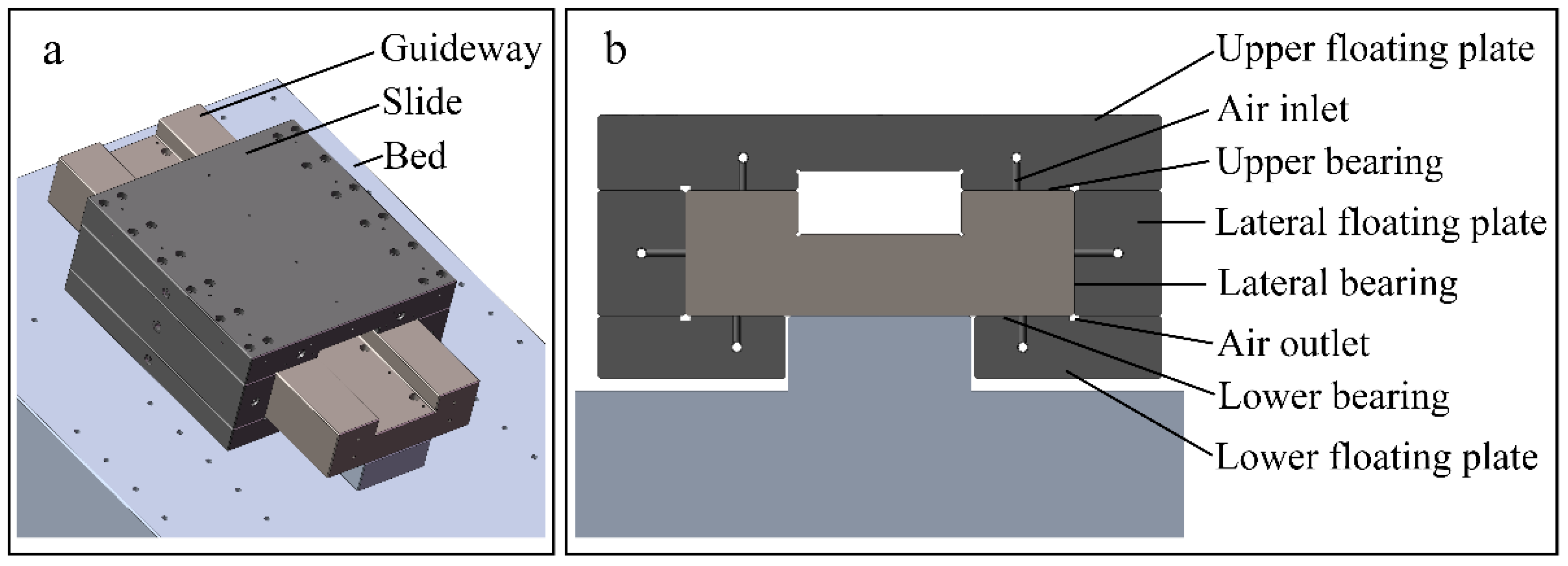
The studied aerostatic slide is from an ultra-precision machine tool, which is shown in
Figure 1. Two lateral aerostatic bearings support the slide in the lateral direction and the other four aerostatic bearings in the normal direction. The lateral and normal directions are the horizontal and vertical directions in
Figure 1b, respectively.
Under external and supporting forces, the displacement and deformation of the slide in the normal and lateral directions can change the shapes and dimensions of the six supporting bearings and thus affect the stiffness of the aerostatic slide. In the cutting process, the external lateral force on the slide is mainly from the cutting force, which is small. Its effect on the lateral stiffness of the aerostatic slide can be ignored. Besides, the linear motor counteracts the external force in the feed direction. Only the external force in the normal direction,
Fn, and the supporting forces from the bearings should be considered. The external moment is small and can also be ignored. Therefore, for the upper or lower bearings, the supporting forces from the left and right bearings are equal. The upper and lower supporting forces,
F1 and
F2, are from the two upper and lower bearings, which are applied on the contact surfaces between the slide and supporting bearings in the normal direction. Hence, the supporting forces from the single upper and lower bearings are
F1/2 and
F2/2, respectively. If a very small external lateral force,
Fs, is applied on the barycenter of the slide as shown in
Figure 2, the slide will move a distance,
d. Then the film thickness of the left lateral bearing,
h3L, decreases, and thus the left lateral supporting force,
F3L, increases. On the contrary, the film thickness of the right lateral bearing,
h3R, increases and the right lateral supporting force,
F3R, decreases. The resultant forces of
F3L and
F3R will change from 0 to a force that is equal in magnitude but opposite in direction to
Fs, making the slide static again. The relationship between
Fs and the two lateral supporting forces is shown as:
The lateral stiffness of the aerostatic slide,
ks, is the derivative of
Fs with respect to
d, which can be written as:
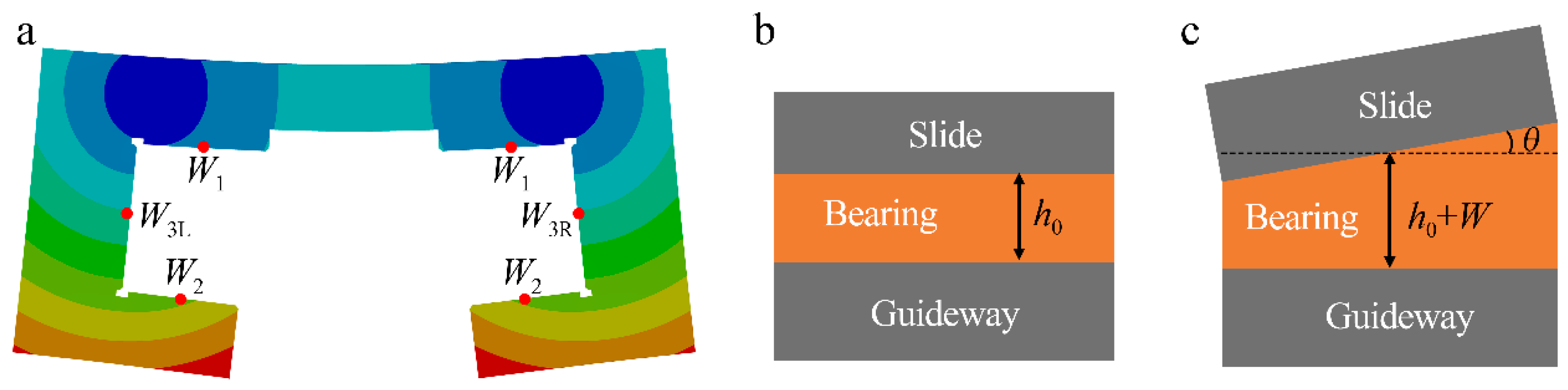
When high-pressure air is supplied to the bearings, the slide will deform under the six supporting forces, as shown in
Figure 3a.
W1 and
W2 are the deformation values of the upper and lower supporting surfaces’ center lines parallel to the feed direction in the film thickness direction.
W3L and
W3R are the deformation values of the left and right lateral supporting surfaces’ center lines. The shapes of the six air films will change from cuboid to wedge, which can be defined by two parameters for every air film. One is the deformation value of the supporting surfaces’ center line parallel to the feed direction in the film thickness direction,
W. The other one is the wedge angle,
θ. The shapes of the supporting bearing before and after the slide deforms are shown in
Figure 3b,c, where
h0 represents the designed film thickness. The solid deformation of the supporting surface can be seen as the superposition of the supporting surface moving along the film thickness direction by
W and rotating around the center line by
θ.
W changes the film thickness of the aerostatic bearing and
θ changes the shape. In fact, the wedge angles of the six supporting bearings are less than 200 μrad and hardly change the supporting forces. If the wedge angle of the lower supporting bearing increases from 0 to 200 μrad, its supporting force only increases by 1.16%, and thus the influence of wedge angle on the supporting forces can be ignored. The supporting force from the bearing can be obtained by calculating the CFD model of the bearing, whose film thickness is
h0 plus
W.
The left and right lateral film thicknesses,
h3L and
h3R, can be expressed as:
d can be obtained from Equation (3), as shown in:
When the external lateral force is 0,
F3L is equal to
F3R. In this case,
W3L is equal to
W3R. The relationship between
W3L or
W3R and the supporting forces can be obtained by the finite element method, which is shown as Equation (5). In this equation,
W3 represents
W3L or
W3R, and
F3 is equal to
F3L and
F3R.
The functional relationship in Equation (5) is linear because the solid deformation is small and the structural material is linear. The change in
F3L hardly changes
W3R, and the change in
F3R hardly changes
W3L. When the external lateral force is small, Equation (5) can be rewritten as:
Subtracting
W3R from
W3L in Equation (6) gives Equation (7), where
λ is 2.885 × 10
−3.
The supporting force from the bearing decreases with the increase in film thickness. The relationship between the supporting force and the film thickness can be obtained by the CFD method. The design parameters of the left and right lateral bearings are identical. The functional relationship between
F3L and
h3L,
f, is equal to that between
F3R and
h3R, as shown in:
Combining Equations (1), (2), (4), (7) and (8) yields:
Equation (9) can be written as:
For a lateral supporting bearing whose film thickness is
h, its thrust stiffness,
kfs, is the derivative of the opposite number of its supporting force with respect to
h, as shown in:
Substituting for
h and ∆
h in Equation (11) using
h =
h3L and ∆
h =
h3R −
h3L gives:
The lateral structural stiffness,
kss, is defined as the derivative of
F3 with respect to
W3. The change in
F3 barely changes
F1 and
F2.
kss can be deduced by Equation (5), as shown in:
When
h3R −
h3L tends towards 0,
d tends towards 0, and vice versa. The two tendencies are identical. Combining Equations (10), (12) and (13) gives:
It can be seen that
ks can be directly induced if
kfs and
kss are known. The lateral stiffness of the aerostatic slide has a functional relationship with that of the lateral bearings and solid structure. The lateral bearing can be regarded as a linearly elastic body in the film thickness direction when its film thickness changes a little, which is similar to a spring in the lateral direction. The lateral supporting surface deforms under the lateral supporting force, and the relationship between
W3 and
F3 is linear, which is similar to a spring deforming under an external force. In fact, Equation (14) can be obtained directly if the lateral bearings are seen as two springs and the slide is seen as an assembly consisting of a rigid body and two springs, as shown in
Figure 4. One end of the spring representing the lateral bearing connects the guideway, and the other end connects the spring representing the slide. The stiffness constants of the springs representing the lateral bearing and slide are
kfs and
kss, respectively.
The structure of the slide and the two lateral bearings is elastic in the lateral direction. When a lateral force is applied on the slide, the two lateral floating plates will deform to counteract a part of the force, and the film thicknesses of the two lateral bearings will change to counteract the rest of the force. Therefore, the lateral stiffness of the aerostatic slide derives from both the solid structure and the supporting bearings. Therefore, this paper proposes a theory for the stiffness of the aerostatic spindle and slide, which is that the stiffness derives from both the solid structure and the supporting bearings and can be obtained by seeing the supporting bearings and the solid structure as springs.
The lateral stiffness will be calculated based on Equation (14) to verify the proposed theory. The film thickness of the lateral bearing can be calculated by the transient FSI method, which is 20.61 μm when the slide bears no load; namely,
Fn is the gravity of the slide. The lateral support forces with the lateral film thickness,
h3, in the range of 18 μm to 25 μm can be calculated by the CFD method, which are shown in
Figure 5. The functional relationship between
F3 and
h3 can be obtained through 2-order polynomial fitting, as shown in Equation (15). The fitting curve is shown as the red curve in
Figure 5.
kfs is the derivative of the opposite number of
F3 with respect to
h3, as shown in:
kfs can be obtained by substituting h3 = 20.61 into Equation (16), which is 315.56 N/μm. kss can be obtained based on Equation (13), which is 346.62 N/μm. Therefore, ks is 330.4 N/μm according to Equation (14), which is significantly less than double kfs.
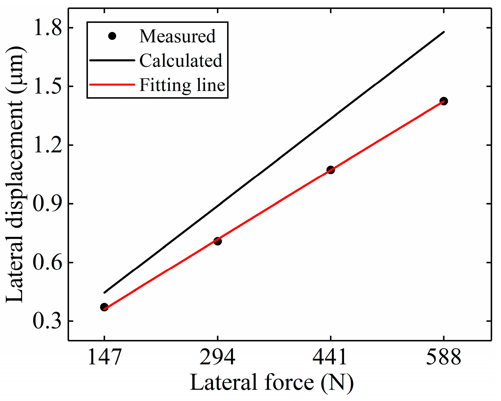
The tests for the lateral stiffness of the aerostatic slide are conducted to verify the calculation. The lateral displacements of the slide under four external lateral forces are measured to obtain the lateral stiffness. Eight steel blocks are used to apply the lateral forces, as shown in
Figure 6. The gravity of the steel blocks is converted into lateral force by two pulleys. The mass of each steel block is 7.5 kg. Four lateral forces can be applied by using two, four, six, and eight steel blocks, which are 147 N, 294 N, 441 N, and 588 N, respectively. A capacitive displacement sensor is used to measure the lateral displacements. To decrease the influence of the solid deformation, the measuring position is in the middle of the upper surface of the slide.
For each external lateral force, the measurement is repeated five times. The lateral displacements under the four lateral forces are shown in
Table 1.
Figure 7 shows the lateral displacements under the four lateral forces, which are measured and calculated based on the proposed theory. The measured lateral displacements are fitted by a proportional function. The fitting line is shown as the red line in
Figure 7. The slope of the fitting line is 0.00246. Hence, the measured lateral stiffness is 406.5 N/μm, which approaches the calculation. The error between them is 18.7%.
3. Normal Stiffness of an Aerostatic Slide
The lateral stiffness of the aerostatic slide follows the proposed theory well. The proposed theory should be valid for the stiffness of the aerostatic slide in other directions. This section will prove the theory of normal stiffness. According to the proposed theory, the two upper supporting bearings are seen as two springs whose stiffness,
kfn1, is the thrust stiffness of the upper bearing. Similarly, the two lower supporting bearings are seen as two springs whose stiffness,
kfn2, is the thrust stiffness of the lower bearing. The slide is seen as an assembly consisting of a rigid body and four springs that connect to the four springs representing the upper and lower bearings, as shown in
Figure 8. The stiffness of the springs connecting to the springs representing the upper bearings,
ksn1, is the derivative of the supporting force from the upper bearing with respect to
W1. The stiffness of the springs connecting to the springs representing the lower bearings,
ksn2, is the derivative of the supporting force from the lower bearing with respect to
W2. The normal stiffness of the aerostatic slide can be directly obtained from
Figure 8, as shown in Equation (17), which will be verified to prove that the proposed theory is also valid for the normal stiffness of the aerostatic slide.
When the external normal force, which is
Fn in
Figure 2, changes, the slide will displace in the normal direction to make the slide stable again. Supposing the change of
Fn is ∆
Fn and the corresponding displacement of the slide is
d, the normal stiffness of the aerostatic slide,
kn, can be expressed as:
If ∆
Fn is positive, the slide will displace in the gravity direction. Then the upper supporting force
F1 will increase and
F2 will decrease to counteract ∆
Fn. Let the changes in
F1 and
F2 be ∆
F1 and ∆
F2, respectively. ∆
Fn is equal to ∆
F1 minus ∆
F2. Hence Equation (18) can be rewritten as:
The supporting forces from the single upper and lower bearings are
F1/2 and
F2/2, respectively. Because ∆
F1 and ∆
F2 are very small,
ksn1 and
ksn2 can be expressed as Equation (20), where ∆
W1 and ∆
W2 are the changes of
W1 and
W2 due to the changes of
F1 and
F2.
The changes in the film thicknesses of the upper and lower supporting bearings, ∆
h1 and ∆
h2, can be obtained based on ∆
W1, ∆
W2, and
d, as shown in:
kfn1 and
kfn2 are the opposite numbers of the derivatives of
F1/2 and
F2/2 with respect to
h1 and
h2, respectively, as shown in:
Substituting for ∆
h1 and ∆
h2 in Equation (21) using Equation (22), and ∆
W1 and ∆
W2 using Equation (20), gives:
Substituting Equation (23) into Equation (19) can give Equation (17). Hence, the proposed theory is valid for the normal stiffness of the aerostatic slide.
4. Thrust Stiffness of the Aerostatic Spindle
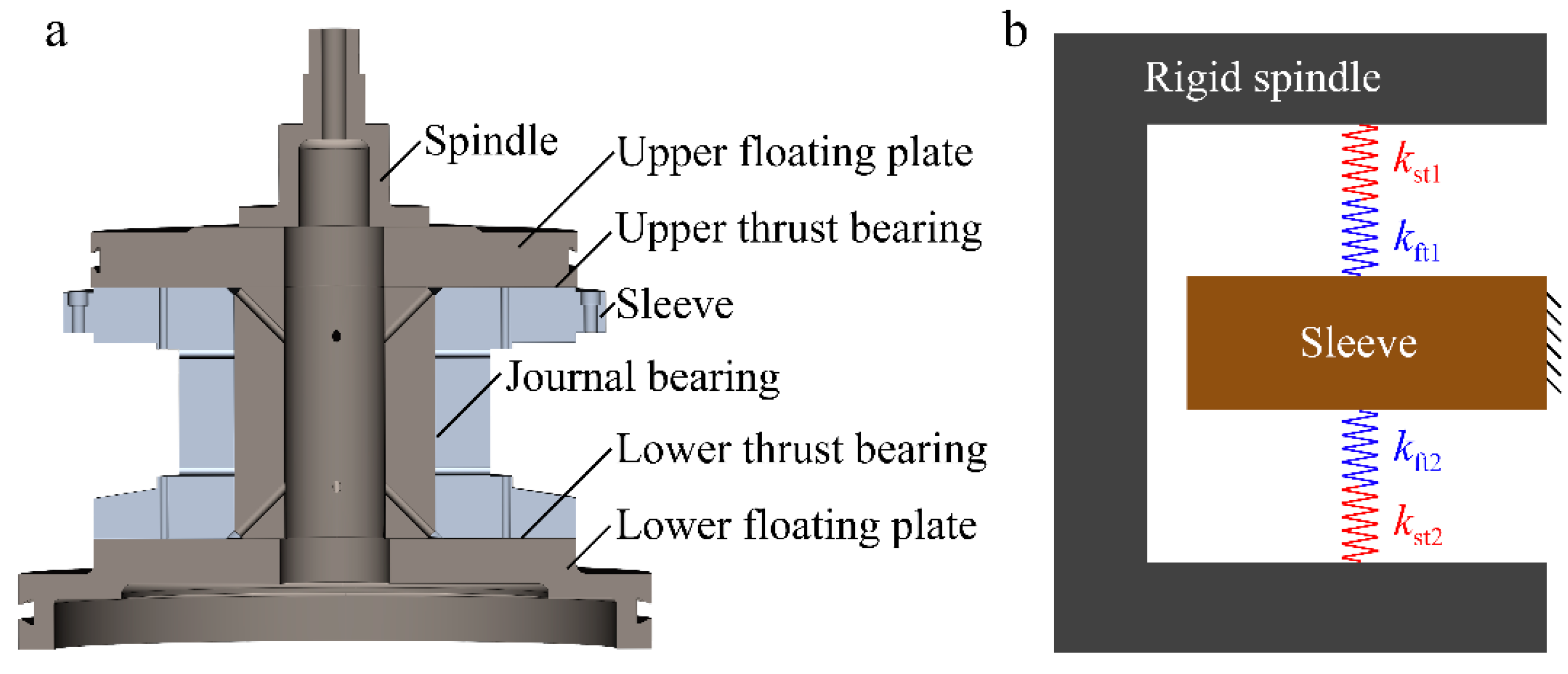
This section will analyze whether the proposed theory is valid for the thrust stiffness of the aerostatic spindle. The studied aerostatic spindle is from a fly-cutting machine tool. Its configuration is shown in
Figure 9a. The aerostatic spindle is H-shaped. Two thrust bearings support the spindle in the axial direction. According to the proposed theory, the upper and lower supporting bearings are seen as two springs whose stiffness constants,
kft1 and
kft2, are the thrust stiffness values of the upper and lower bearings, respectively. The spindle is seen as an assembly consisting of a rigid body and two springs that connect to the two springs representing the upper and lower thrust bearings, as shown in
Figure 9b. The spindle and sleeve will deform under the supporting forces from the upper and lower thrust bearings,
F1 and
F2. The deformation of the sleeve is small compared with the spindle, which will be ignored. The stiffness constants of the springs connecting to the springs representing the upper and lower bearings,
kst1 and
kst2, are the derivatives of
F1 and
F2 with respect to
W1 and
W2, respectively, which are the axial deformation values of the middle rings of the upper and lower supporting surfaces.
The thrust stiffness of the spindle,
kt, can be directly obtained from
Figure 9b, as shown in:
Similar to the normal stiffness of the aerostatic slide, Equation (24) can be verified in the same way. The thrust stiffness calculated by the steady FSI method is 2043.5 N/μm, which accords with the experimental result of 2224.9 N/μm [
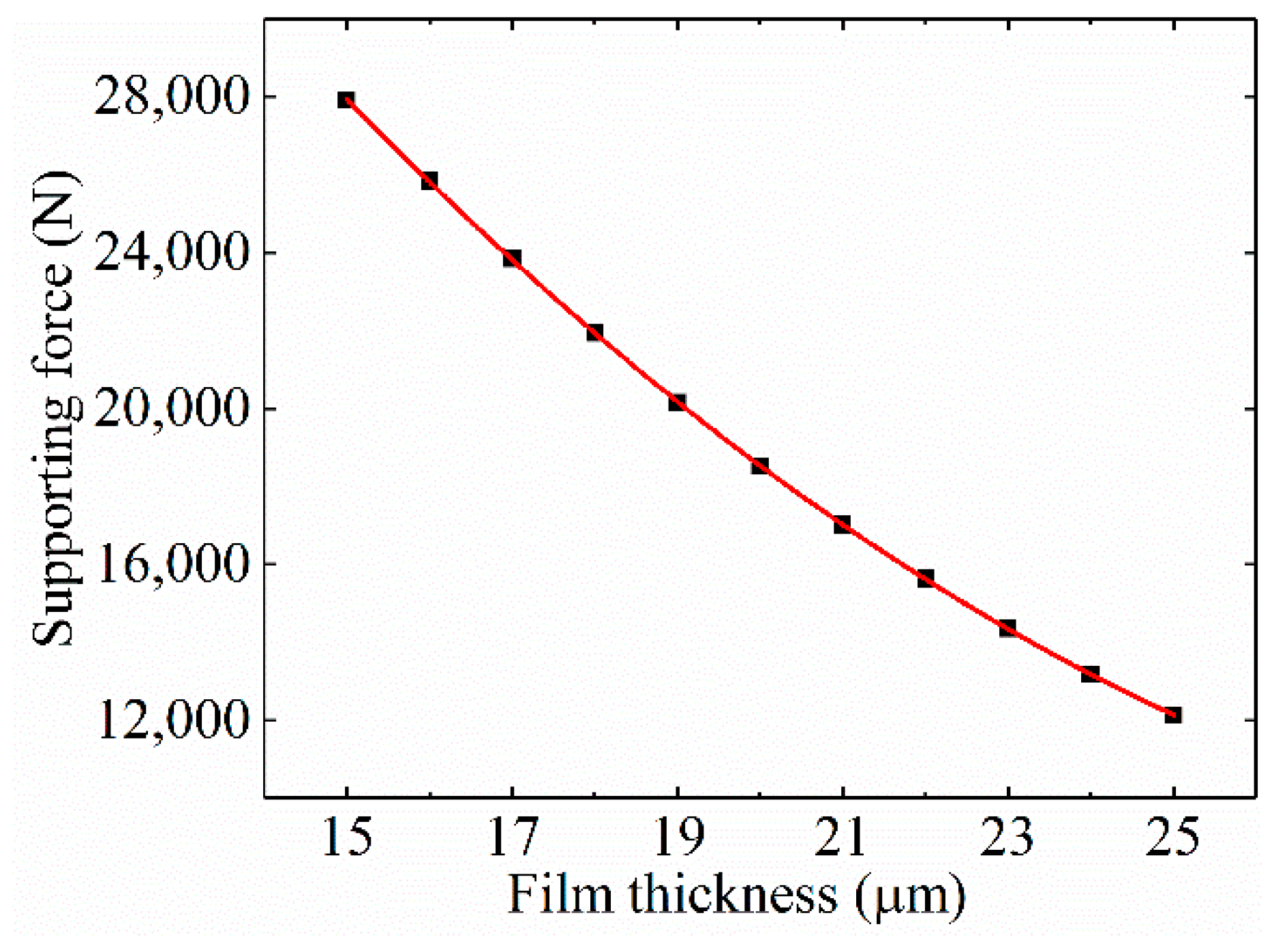
22]. The thrust stiffness will be calculated based on Equation (24), which will be contrasted with 2043.5 N/μm. The film thicknesses of the upper and lower thrust bearings can be obtained based on the transient FSI method, which are 18.76 μm and 20.43 μm, respectively. The design dimensions of the upper and lower bearings are identical. The supporting forces from the upper or lower thrust bearing under the film thicknesses from 10 μm to 25 μm can be obtained based on the CFD method, as shown in
Figure 10.
The relationship between the supporting force and the film thickness can be obtained by 2-order polynomial fitting, as shown in Equation (25). The fitting curve is shown as the red curve in
Figure 10.
kft1 and
kft2 are the opposite numbers of the derivatives of
F1 and
F2 with respect to
h1 and
h2, respectively. The opposite number of the derivative of
F with respect to
h is shown as:
kft1 and kft2 can be obtained by substituting h = 18.76 μm and h = 20.43 μm into Equation (26), which are 1728.32 N/μm and 1528.00 N/μm, respectively. The changes in the lower and radial supporting forces barely deform the upper floating plate. Moroever, the changes in the upper and radial supporting forces barely deform the lower floating plate. Therefore, based on the finite element method, kst1 and kst2 can be obtained by calculating the solid deformation under the upper and lower supporting forces, which are 3866.31 N/μm and 2876.13 N/μm, respectively. Substituting the values of kft1, kft2, kst1, and kst2 into Equation (24) gives kt = 2192.3 N/μm, which is nearly identical to the normal stiffness values obtained by the steady FSI method and experiment.
5. Discussion
The proposed theory is also valid for the stiffness of the static pressure spindle and slide in other directions, which can also be verified. However, the influence of FSI on the radial stiffness of static pressure spindles is generally small. This is because the small radial solid deformation hardly changes the shape and dimensions of the journal bearing, and the radial structural stiffness is large. Moreover, for the angular stiffness of static pressure spindles and slides, the supporting forces change the shapes and dimensions of the supporting bearings and thus change the angular stiffness of the bearings. However, the external moment is basically counteracted by the reaction moment due to the deformation of the supporting bearings. In other words, the angular structural stiffness is much greater than the angular stiffness of the supporting bearings. The angular stiffness of the static spindle or slide is nearly equal to that of their supporting bearings. For the above reasons, the proposed theory for the stiffness in these directions will not be introduced in this paper.
Based on the proposed theory, there are two ways to enhance the stiffness of the static pressure spindle and slide. One is to increase the stiffness of the supporting bearings, and the other is to increase the structural stiffness. For a system with only a supporting bearing, suppose the structural stiffness is
λ times the stiffness of the bearing. According to the proposed theory, the system stiffness,
k, is shown in Equation (27) where
kf is the stiffness of the bearing.
The ratio of
k to
kf is
λ/(1 +
λ), which increases with the increase of
λ, as shown in
Figure 11. It can be seen that when
λ is less than 2, the ratio grows fast with the increase of
λ. But when
λ is greater than 4, the growth of the ratio slows considerably. Increasing the structural stiffness will inevitably increase the dimensions and mass of the solid, which will decrease the natural frequencies and degrade the drive properties of the spindle and slide. Therefore,
λ should be in a reasonable range. This paper suggests that
λ should be around 3. When
λ is 3, the system stiffness is 75% of the stiffness of the bearing. When
λ is greater than 4, the increase of
λ will not enhance the system stiffness effectively. In this case, increasing
kf will be a more proper way to enhance
k.
When the structure of a static pressure spindle or slide is confirmed, the next step is to choose suitable structural dimensions
s and a designed film thickness
h0, which are critical at the design stage. To make the stiffness value of the static pressure spindle or slide
kc reach the designed value
k, lots of
kc under different structural dimensions and designed film thicknesses have been calculated to find the suitable parameters based on the conventional method, as shown in
Figure 12a. It can be seen that the conventional method is a little bit blind and inefficient. For this problem, a method based on the proposed theory is proposed to choose suitable structural dimensions and designed film thickness, as shown in
Figure 12b. First, the bearing and structural stiffness values,
kf and
ks, can be obtained on the basis of
k and
λ, and thus the actual film thickness after the solid deforms
h and structural dimensions
s can be determined, respectively. Then, based on the FSI method, the designed film thickness
h0 can also be obtained. Hence,
s and
h0 can be determined on the basis of
k and
λ. It can be seen that the method based on the proposed theory is more efficient than the conventional method.


