Article

A Study on the Impact of DPF Failure on Diesel Vehicles Emissions of Particulate Matter

1
Graduate School of Automotive Engineering, Kookmin University, Seoul 02707, Republic of Korea
2
Automobile Department, Gyeonggi University of Science and Technology, Siheung 15079, Republic of Korea
3
Department of Automotive Engineering, Kookmin University, Seoul 02707, Republic of Korea
*
Authors to whom correspondence should be addressed.
Appl. Sci. 2023, 13(13), 7592; https://doi.org/10.3390/app13137592
Submission received: 3 May 2023 / Revised: 16 June 2023 / Accepted: 20 June 2023 / Published: 27 June 2023
(This article belongs to the Section Environmental Sciences)

Abstract

:
A diesel particulate filter (DPF) is an after-treatment device designed to capture and store exhaust particulate matter emitted by diesel vehicles. DPFs are damaged owing to complex reasons, such as regeneration processes and loads generated during driving. While DPFs can be damaged, they can also be manipulated, especially DPFs with hollow damage. In such cases, the filtration performance deteriorates significantly, and excessive amounts of smoke and ash are emitted during driving, resulting in environmental pollution. In this study, DPF damage types were observed using the CR X-ray imaging technique without removing the DPF. In addition, it was experimentally determined that the five types of DPF shapes (normal, crack, melt, plug, and hollow) caused increases in the particle number (PN) and smoke concentration. Experiments were conducted in the Korea Diesel 147 (KD-147) vehicle driving mode, and the PN and smoke concentration were measured using a nanoparticle emission tester 3795 (NPET-3795-HC) and opacimeter (OPA-102). The experiment was conducted 10 times for each type of DPF damage. As a result of the experiment, no significant difference was found between the normal DPF and crack-damaged DPF in terms of smoke emission, but there was a definite difference in the smoke concentration relative to the other DPF damage types. DPF of all damage types satisfied Korea’s smoke concentration regulation. In addition, the PN emission characteristics differed clearly in terms of the values measured for each damage type, and, unlike the smoke concentration characteristics, there was a clear difference in the PN emission characteristics of various DPF damage types. In addition, the PN concentration tended to increase in the rapid acceleration section of the KD-147 vehicle driving mode for all DPF damage types.

1. Introduction

Particulate matter in automobile exhaust gas is one of the targets of exhaust gas regulations, and it is the main cause of problems due to air pollution [1]. The government of the Republic of Korea established the “Basic Plan for Air Quality Management in the Metropolitan Area” in 2005 to improve the air environment in metropolitan areas, where air pollution is severe [2]. Under this plan, the “Atmospheric Environment Improvement Project in the Metropolitan Area” is being executed, and, as part of this project, the “Emission Reduction Project for Old Diesel Vehicles of Environment” (2021) has been promoted for diesel vehicles, which have the greatest impact on the atmospheric environment in metropolitan areas. Through the above project, as of 2018, approximately 490,000 old diesel cars were scrapped early, approximately 510,000 were equipped with diesel particulate filters (DPF), and approximately 200,000 were retrofitted with LPG engines. All of these vehicles were pre-Euro 3, but they were either scrapped or upgraded to Euro 4 under the project, which contributed greatly to reducing the particulate matter emissions in metropolitan areas [3].
In a vehicle equipped with a DPF, management through periodic inspection is required to prevent DPF aging. When the substrate is aged, internal damage occurs due to complex reasons, such as local thermal stress generated during the regeneration process, vibration generated during driving, and increased back pressure with the accumulation of particulate matter (PM) [4]. If a DPF is damaged, its performance in filtering particulate matter emissions decreases significantly. When a vehicle equipped with such a damaged filter is driven, excessive amounts of smoke and ash are emitted, resulting in increased air pollution. However, according to recent audit results obtained in the Republic of Korea, exhaust gas from diesel vehicles has increased owing to the poor management of DPF-equipped diesel vehicles. Because the DPF is managed separately without on-board diagnostics (OBD) interlocking, it is not easy to clearly identify the DPF status (crack, melting, plug, and hollow) through regular periodic inspections such as smoke concentration inspection, OBD diagnosis, and removal visual inspection, and visual inspection is a time-consuming endeavor. In this study, the DPF sample comprised 300 units that were attached to various vehicles after being certified by the Republic of Korea’s Ministry of Environment but were detached from these vehicles and stored separately owing to reasons such as damage.
Various types of studies have been conducted to confirm the state of the substrate inside the DPF using X-rays. For example, research has been conducted to quantify the accumulation of soot and ash by linearly approximating the change in substrate density of a DPF on the basis of differences in X-ray transmittance [5]. In addition, scanning electron microscopy–energy-dispersive spectrometry (SEM-EDS), X-ray photoelectron spectroscopy (XPS), and X-ray diffraction (XRD) have been applied to analyze the physicochemical characteristics of crack, melt, hollow, and plug fractures. In one study, the mechanism of DPF failure was investigated and confirmed [6]. Other works include studies aimed at shaping DPF internal substrate images using computed tomography (CT) X-rays and numerical analysis algorithms [7] and CT X-rays conducted by Waseda University and the National Institute of Advanced Industrial Science and Technology in Japan. In another study, the movement and accumulation of ash were investigated using CT X-ray images. However, all the research methods described above have the drawback that the process of removing the DPF from the vehicle and conducting a precise analysis is time-consuming [8]. Therefore, these methods were judged to be unsuitable from the perspective of commercializing DPF damage diagnosis. Non-destructive imaging using computed radiography (CR) X-rays is considered an alternative to solve these problems. With this technique, it is possible to obtain images without removing the DPF in advance and to acquire DPF internal substrate images within a short time. Optimal imaging conditions according to the DPF size were established using the CR X-ray imaging technique, and crack, melting, hollow, and plug damage patterns of the DPF substrate were observed. In addition, after arbitrarily accumulating smoke and ash, the DPF substrate was photographed to confirm the possibility of diagnosing accumulation qualitatively [9]. However, no study has been conducted thus far to determine the effect of the DPF damage type on exhaust gases in an actual vehicle. In this study, X-ray images were analyzed to define the DPF damage types and to identify the smoke and particle number (PN) emission effects corresponding to each type of damage [10].

2. Experimental Apparatus and Procedure

2.1. Experimental Apparatus

2.1.1. CR X-ray Imaging

In this study, the CR X-ray imaging technique was used to read the DPF damage type. The CR X-ray imaging setup consisted of an X-ray emitter, an image plate (IP), and a CR reader. Herein, as the X-ray emitter, a GXR-S (DRGEM, Inc., Gyeonggi-do, South Korea) was used, which is commonly used in the medical field. A preliminary study verified that this model can be used to image DPFs of various sizes equipped in vehicles. As the IP and CR reader, products offered by Konica Minolta were used. The IP standard was inches, and a Regius 110 CR reader was used. The IP stored internal tomographic images of the object irradiated with X-rays, and the CR reader output the image stored on the IP [11].

2.1.2. Vehicle Emission Test

In this study, an HDC-1000 (DASAN RND, Inc., Gyeonggi, Korea) was used as the chassis dynamometer. A chassis dynamometer is used for the “exhaustive gas inspection of running vehicles”, as stipulated in May 2002 in the “Air Quality Conservation Act” under the jurisdiction of the Ministry of Environment, Republic of Korea [12]. After the image acquisition of the damaged DPF, exhaust gas analysis was conducted by installing the damaged DPF on the experimental vehicle. A smoke concentration meter (OPA-102, DANSAN RND, Inc.) and a nanoparticle emission tester (3795-HC, NPET TSI, Inc., MN, USA) were used to measure the exhaust gases. The OPA-102 is a device that measures the concentration of smoke generated by diesel vehicles using the light transmission method. This method not only eliminates the measurement error associated with reflective meters but also measures the exhaust generated during operation in real time. The NPET-3795-HC is a vehicle-mountable Portable Emissions Measurement System (PEMS) device that measures the number of particles in the exhaust gas emitted by a diesel vehicle while driving on a real road. This device can sample exhaust gases at temperatures of up to 300 °C and remove volatile particles using a catalyst-based remover to measure only solid particles. The measurable particle diameter range was 23–1000 nm, and the number concentration range was 103–106 particles/cm3. As the experimental vehicle, a 2005 Santa Fe-SM 2WD model equipped with a 2013 compound regenerative exhaust gas reduction device (DOC + DPF) (Econics, Inc.) was prepared, and its exhaust gas characteristics resulting from DPF damage were analyzed [13]. The vehicle had traveled 134,000 km at the time of testing, and it was equipped with a 2.0 L VGT D4EA engine. The specifications of the experimental vehicle are listed in Table 1.

2.2. Experimental Method

2.2.1. CR X-ray DPF Imaging Method

DPF imaging was conducted by following the process described in “Feasibility Study on Determining DPF Damage Using CR X-ray Technique” [14]. When the DPF was placed on the X-ray imaging table and irradiated with X-rays, an internal image of the DPF was stored on the IP. Thereafter, the IP was inserted into the CR reader, and the image formed as a result of the conversion of the optical signal obtained based on the accumulated dose was output to a monitor. Figure 1 shows the acquisition process for the X-ray images of the DPF [15].

2.2.2. KD-147 Inspection Mode for Diesel Vehicles

In accordance with the “Method for Inspecting Running Vehicle Emissions” described in the “Regulations on Execution of Detailed Exhaust Gas Inspection of Running Vehicle of Environment” (2021), the KD-147 inspection mode is applied to measure the smoke concentrations of diesel vehicles. In this study, we attempted to compare the PN emission pattern of the experimental vehicle under severe conditions corresponding to various types of DPF filter failure. Therefore, the experiments were conducted by applying the KD-147 test mode, which is currently the standard in the Republic of Korea. The KD-147 inspection mode proceeds as follows: road load horsepower setting, preheating mode, and driving mode, as summarized and illustrated in Table 2 and Figure 2, respectively. Herein, the road load horsepower value was set automatically to mimic actual road loads by inputting the load horsepower condition, vehicle specifications, and current vehicle speed in the KD-147 SW calculation system. Before proceeding with the KD-147 inspection mode, forced regeneration was performed once for each DPF sample. Then, the vehicle emission was measured when driving from 0 km/h (Idle) to a maximum speed of 83.5 km/h over a period of 147 s in view of the set driving cycle and road load horsepower. The exhaust gas was measured 10 times for each DPF sample, resulting in a total of 50 measurements. The smoke concentration and the number of PM particles were measured in consideration of the type of internal substrate damage. Table 3 lists the number of tests and regenerations for each DPF damage type. The arithmetic averages of the smoke concentration and PM particle number concentration measurements were calculated automatically by the KD-147 inspection mode software, and the KD-147 mode composition was as follows [16].
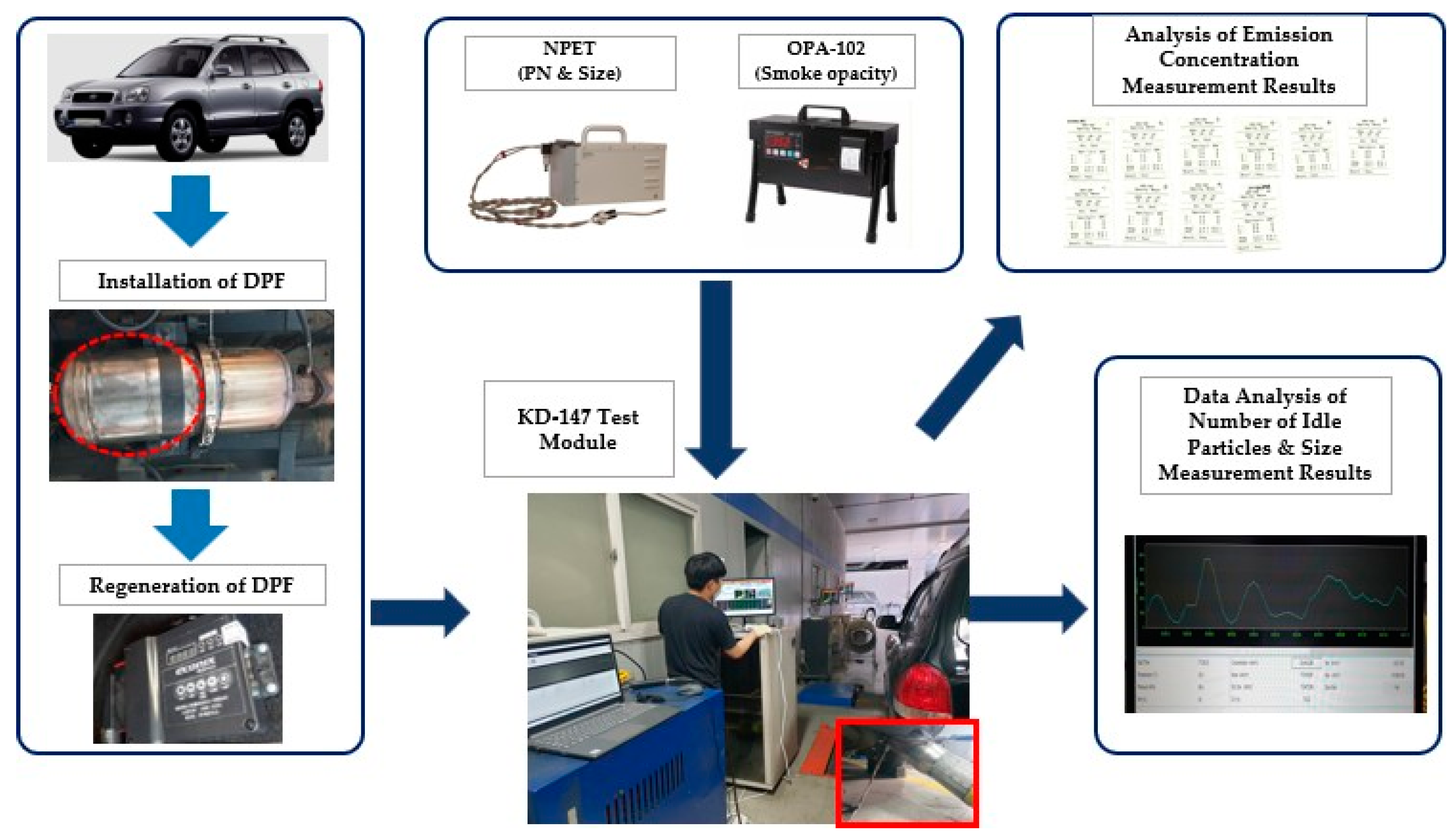
The measured smoke concentration value was the arithmetic average value of 5-s measurements recorded every 0.25 s before and after every 1 s centered on the highest measurement value. The additionally configured NPET-3795-HC synchronized the chassis power and time offset, and it recorded the highest and lowest measured values of PM, as well as the average number of particles per cubic centimeter, in real time. Therefore, by specifying the data separately, the number of particles per second was measured at 1 Hz to determine the number of particles measured in the KD-147 driving mode test time. Figure 3 schematically shows the method used to derive the measured value of the exhaust gas in this study. Table 4 summarizes the PN inspection system for vehicles in operation in the European Union, and the PN results obtained in this study were compared to European values. As mentioned in the Introduction, the DPF used in this study was compliant with the Euro 4 standard. Therefore, the experiment was conducted by adopting the Netherlands’ PN regulation method.

3. Results

As the DPF was attached to the experimental vehicle, the normal, crack, melt, hollow, and plug damage samples, whose conditions were confirmed through CR X-ray imaging, were prepared. Before conducting exhaust gas measurements in the KD-147 driving mode, forced regeneration was performed on the DPF attached to the experimental vehicle to oxidize the PM accumulated on the substrate. In the KD-147 driving mode, the smoke concentration and PN were measured for 147 s for each sample [17].

3.1. How to Read Damaged Parts of DPF from Video Material

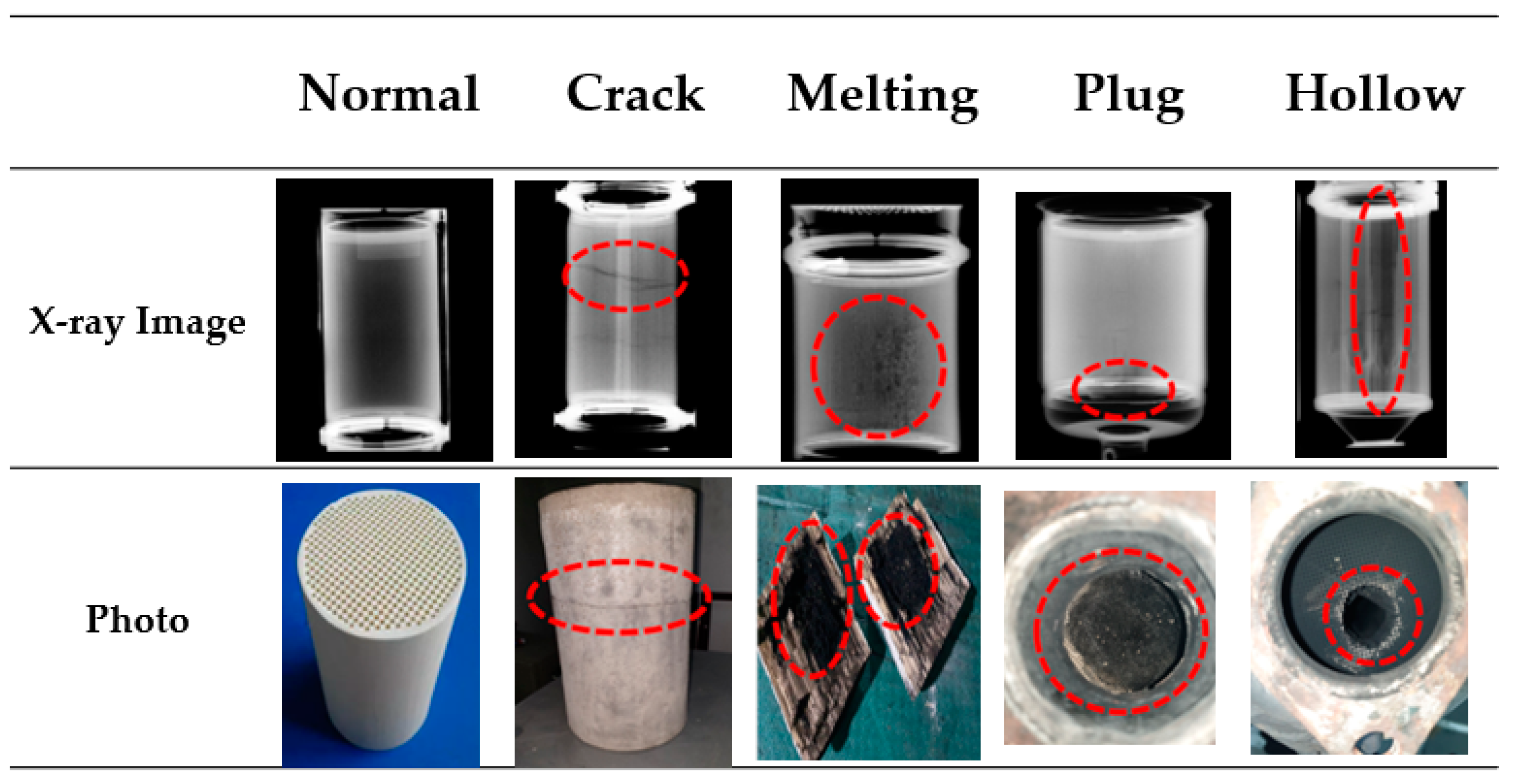
With the CR X-ray imaging technique, the channel pattern inside the substrate can be observed in the images obtained under the optimal imaging conditions [18]. In the images of the normal DPF, patterns other than the substrate-specific channel pattern do not appear. In addition, if the corresponding part appears close to white in the photograph, the density of the DPF substrate is high. By contrast, if it is close to black, the density of the DPF substrate is low. Accordingly, the damage type is read on the basis of abnormal patterns, except for the unique channel pattern of the substrate, and color of the observation area. Images of the video object obtained using X-rays and the corresponding photographs are depicted in Figure 4.
  • Normal
Because the normal DPF was new and unused, no damage was observed in its video. Image processing was performed to confirm the substrate shape in detail, but noise was generated because of the thick DPF canister and low tube current. For this reason, the image of the substrate channel pattern could not be seen.
  • Crack damage
In substrate images of DPFs with crack damage, a black solid line pattern can be observed in the direction perpendicular to the substrate-specific channel pattern in the longitudinal direction. This is depicted as a solid black line because more photons penetrate the small gap created by crack breakage and reach the IP. In this study, if a solid black line pattern was observed on the substrate image, it was judged as crack damage.
  • Melting damage
In substrate images with melting damage, the unique channel pattern of the substrate in the longitudinal direction is abnormally melted and lost. This is because more photons penetrate the molten channel portion than the normal portion and reach the IP, and a dark black color appears locally. In addition, the molten channel is adsorbed and solidified on the surrounding normal channel, resulting in local density, which hinders photon transmission and reduces the number of photons reaching the IP. As such, locally, a dark white color is observed. In this study, if an abnormally melted channel shape and local dark black and white colors around the melted channel part were observed in a substrate image, it was judged as melting damage.
  • Hollow damage
In DPF images with hollow damage, a hollow dark black area is observed from the front to rear in the same longitudinal direction as that of the unique channel pattern of the substrate. This is because dissipation occurs in a hollow form, and the density decreases, resulting in many photons reaching the IP. In this study, a hollow black color on the substrate image was considered a marker of hollow damage.
  • Plug damage
In a normal substrate, channels are arranged in the order of channels with a plug and channels without a plug. Therefore, in the normal case, it is observed that the black channel without a plug and the white channel with a plug are arranged in order at the end of the channel at the rear end of the substrate in a certain size. However, in the images of a substrate with plug breakage, a dark black area can be observed near the channel at the rear end of the substrate, regardless of the order of arrangement of the plug channels. This is because as the plug channel part is lost, the substrate density decreases, and more photons reach the IP than those in the normal part. In this study, if a dark black area was observed at the end of the channel at the rear end of a substrate image, regardless of the order of arrangement of the plug channels, it was judged as plug breakage.

3.2. Measurement of Smoke Concentration by DPF Damage Type

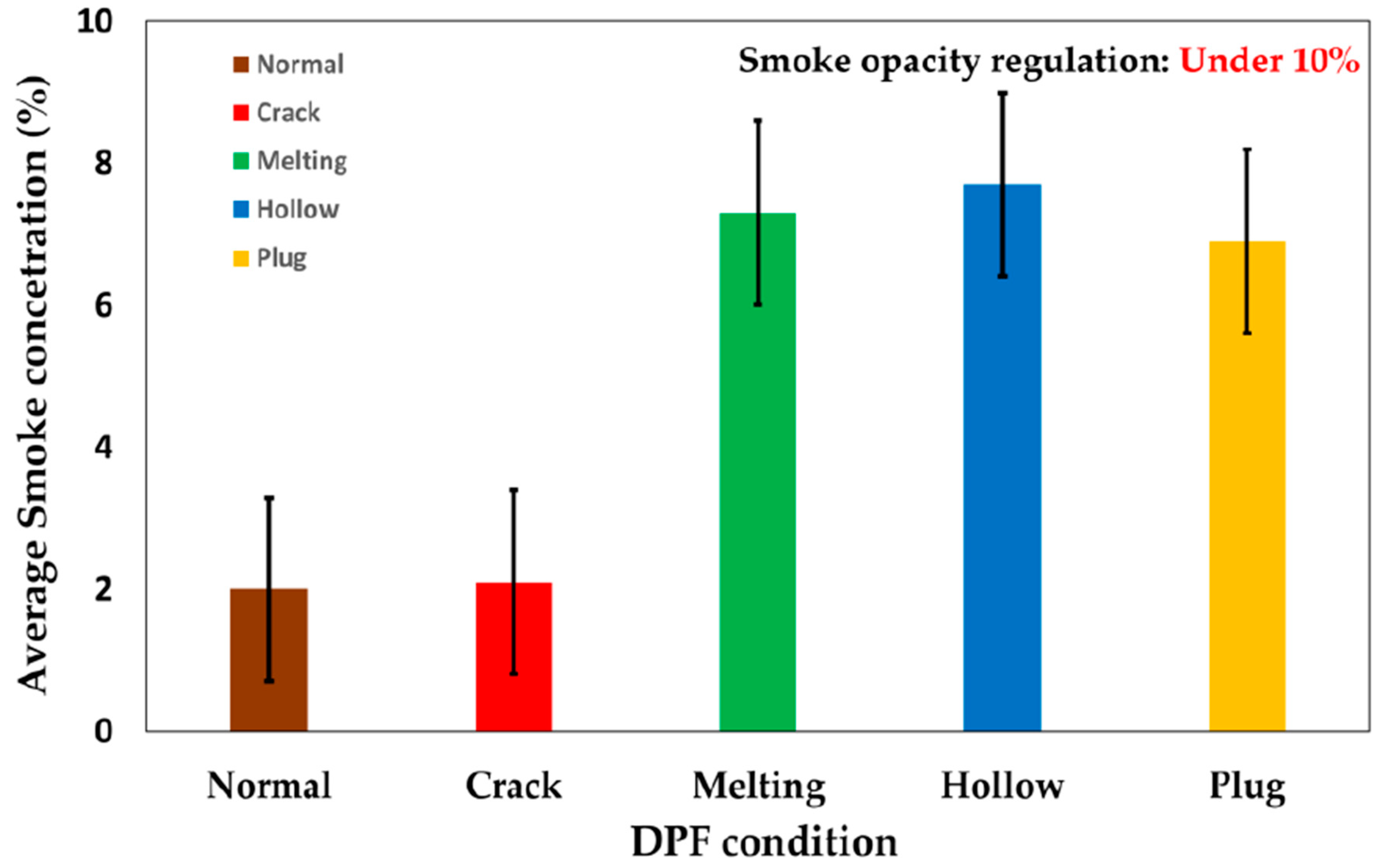
The DPF samples were installed in the experimental vehicle, and KD-147 driving mode tests were conducted. The smoke concentrations of each of the DPF types were measured using the OPA-102, a smoke concentration measurement device, and the results are depicted in Figure 5. In Korea, the smoke concentration is required to be 10% or less, and it was confirmed that this regulation was satisfied for all DPF damage types. However, in the case of the normal and crack-damaged DPFs, the smoke concentration was the lowest at 2%, whereas, in cases of the melt-, hollow-, and plug-damaged DPFs, the smoke concentrations were relatively high at 7% or more. In the case of the melt-damaged DPF, the smoke concentration was 7.3%, and the filtering performance was believed to have deteriorated because the substrate channel had melted. In the case of the hollow-damaged DPF, the smoke concentration was 7.7%, and this was attributed to the reduced filtration performance owing to the center of the inner substrate being hollow and empty. In the case of the plug-damaged DPF, the smoke concentration was 7%, and the deterioration in filtration performance was thought to be caused by damage to the plug that performed the filtering function in the internal substrate [19,20].

3.3. Results of Emission Particle Number Concentration by DPF Damage Type

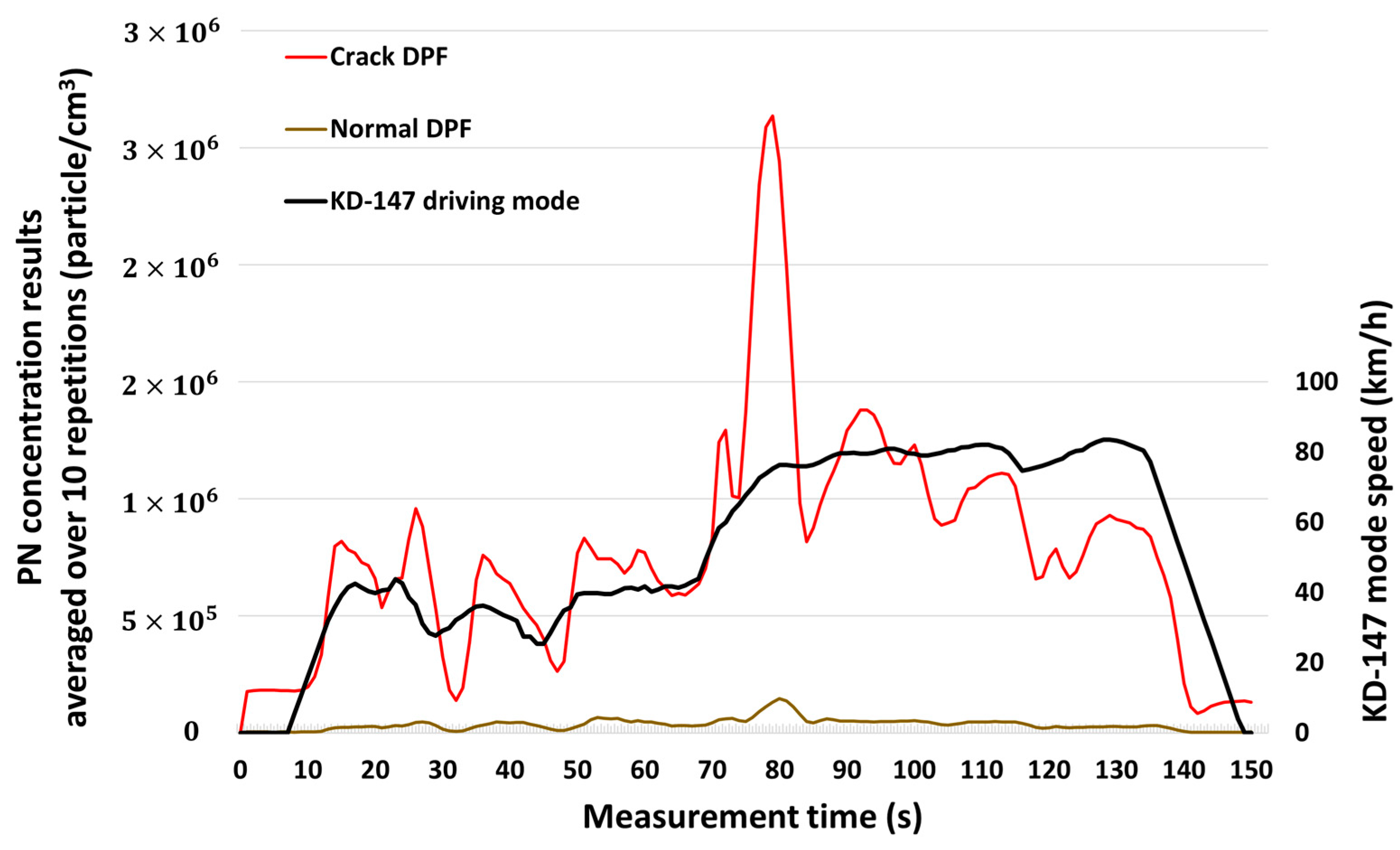
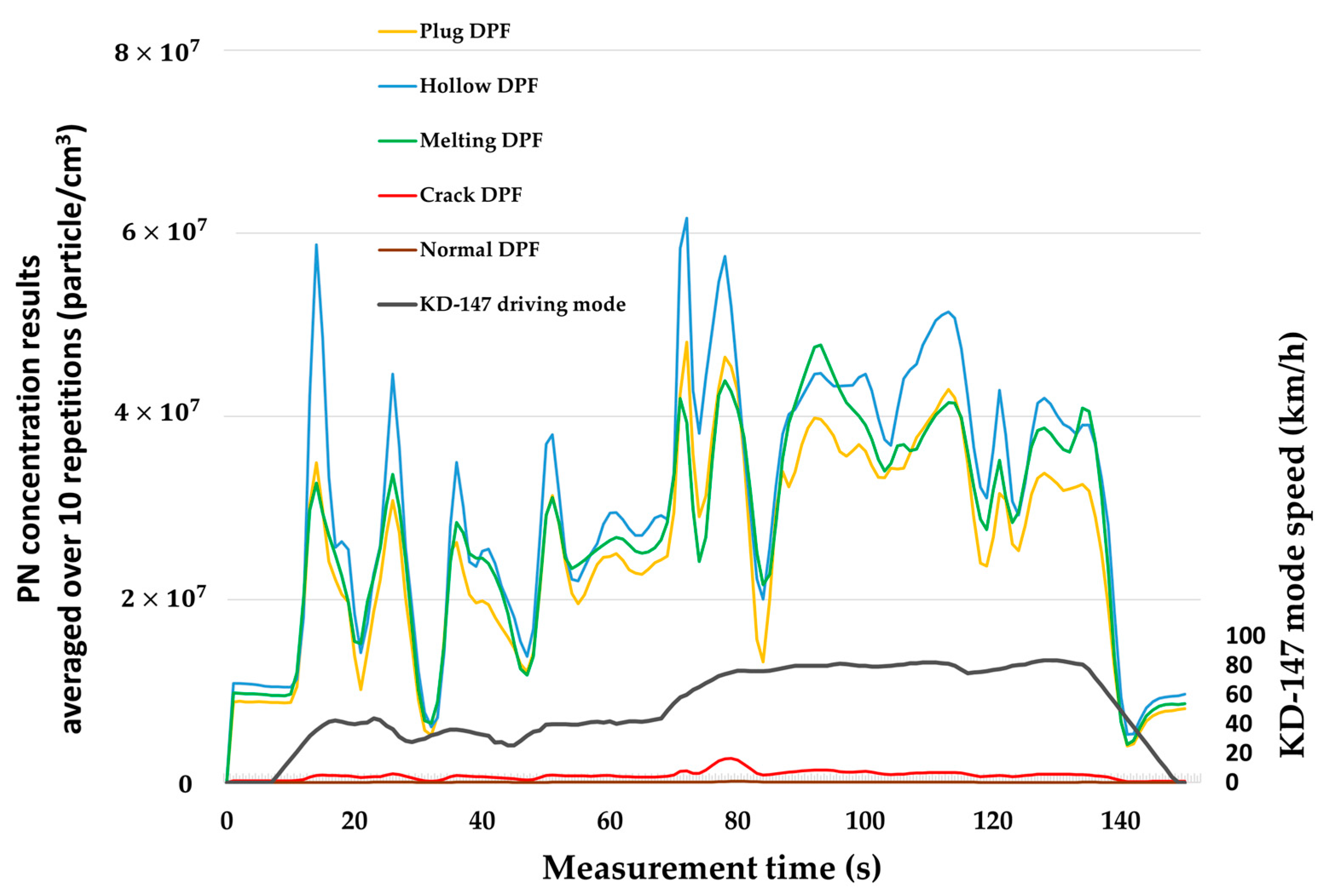
Figure 6 and Figure 7 show the graphs reflecting the average of the measured number of PN per unit volume, measured 10 times in the KD-147 driving mode with DPF samples installed in the experimental vehicle. Overall, the PM concentration increased rapidly when the experimental vehicle accelerated in the KD-147 driving mode, and it decreased when the engine was not loaded during vehicle deceleration or vehicle movement at constant speed. The maximum PM concentration was obtained in the rapid acceleration section of 70–80 s in the KD-147 driving mode. For the normal DPF, the maximum measured value of PN was approximately 1.5 × 10⁵ particle/cm3, and the average PN value measured over 147 s was approximately 3.5 × 10⁴ particle/cm3. For the cracked DPF, the maximum measured PN value was approximately 2.9 × 10⁶ particle/cm3, and the average PN value measured over 147 s was approximately 7.8 × 10⁵ particle/cm3. The maximum measured PN value was approximately 22 times higher than that of the normal DPF. This was attributed to the fact that the light transmission method of the smoke concentration meter was unable to measure the ultra-fine particles emitted from the crack gap. For the melt-damaged DPF, the maximum measured PN value was approximately 5.2 × 10⁷ particle/cm3, and the average PN value measured over 147 s was approximately 2.7 × 10⁷ particle/cm3. This result was attributed to the fact that the substrate channel inside the DPF had melted and moved to the channel without a plug, and PM was discharged in the absence of the filtering function. For the hollow DPF, the maximum measured PN value was approximately 7.1 × 10⁷ particle/cm3, and the average PN value measured over 147 s was approximately 3.0 × 10⁷ particle/cm3. This result was attributed to the fact that the central part of the DPF substrate was completely hollowed out, and it was unable to perform the filtering function properly.
For the plug DPF, the maximum measured PN value was approximately 5.8 × 10⁷ particle/cm3, and the average PN value measured over 147 s was approximately 2.5 × 10⁷ particle/cm3. This result was attributed to damage to the plug that filtered the PM, which decreased the PM reduction efficiency. In this study, DPF samples corresponding to each damage type were mounted on a test vehicle, and KD-147 driving mode tests were conducted to determine the particle concentration emitted during vehicle driving. The results confirmed that all damaged DPFs did not satisfy the PN regulations for operative vehicles in the European Union. Notably, the normal filter did satisfy these regulations. A correlation between the DPF failure type and the effluent concentration was not identified.

4. Conclusions

Using the CR X-ray imaging technique, tomography images of DPF internal substrates were acquired, and the presence or absence of DPF damage and the damage type were identified from the acquired images. In this study, the technical feasibility of the CR X-ray imaging technique was confirmed. In addition, it was found that if the CR X-ray imaging technique were to be used for DPF diagnosis, it would contribute greatly toward improving the atmospheric environment by reducing the time required for DPF performance testing. The measured smoke concentrations of the normal and crack-damaged DPF samples were 2% and 7–8%. In addition, all the damaged DPF samples fulfilled the Korean smoke concentration regulation of 10% or less. The PN concentration discharged during the KD-147 driving mode tests of the melt-, hollow-, and plug-damaged DPFs did not fulfill the PN regulation standards for operative vehicles in the Netherlands. Moreover, the maximum PN concentration discharged during the KD-147 driving mode tests of all the damaged DPF samples did not meet the PN regulation standards for vehicles in operation. During the KD-147 driving mode tests, all DPF samples exhibited a rapid increase in PN emissions owing to an increase in engine load in the rapid acceleration section and a rapid decrease in PN emissions in the constant speed and deceleration sections. In this study, the PN value tended to increase/decrease during the KD-147 driving mode tests. In this experiment, it was difficult to achieve objectivity because the DPF damage samples were not extracted from the same vehicle. Therefore, more accurate results could be obtained if the experiment was conducted by randomly damaging a new DPF in the same vehicle in the future. It appears necessary to conduct research to derive an accurate correlation between the PN emission tendencies of DPFs exhibiting various types of failure.

Author Contributions

Conceptualization, S.O., S.P., T.H., and S.L.; Methodology, G.P., T.H., and S.P.; Investigation, S.P., G.P., and S.L.; Supervision, S.O. and S.L.; Writing—original draft, G.P. and S.P.; Writing—review and editing, S.P. and S.L. All authors have read and agreed to the published version of the manuscript.

Funding

This research was supported partly by the Korea Environment Industry & Technology Institute (KEITI) through the Reduction Management Program of Fine Dust Blind-Spots grant funded by the Korean government (Ministry of Environment (MOE)) (No. 2020003070001) and through the BK21 Program grant funded by the Korean government (Ministry of Education (MOE)) (No. 5199990814084).

Institutional Review Board Statement

Not applicable.

Informed Consent Statement

Not applicable.

Data Availability Statement

All necessary data have been reported in this article and there are no other data to share.

Conflicts of Interest

The authors declare no conflict of interest.

Abbreviations

The following abbreviations are used in this manuscript:
DPFDiesel Particulate Filter
SCRSelective Catalyst Reduction
PMParticulate Matter
OPA-102Opacity Meter
NPET-3795Nanoparticle Emission Tester

References

  1. DieselNET_EU: Periodic Technical Inspections (PTI). Available online: https://dieselnet.com/standards/eu/pti.php (accessed on 2 May 2023).
  2. Korea Ministry of Environment (MOE). Comprehensive Plan Report of Measures for Particulate Matter Management. 2019. Available online: http://www.me.go.kr/home/web/policy_data/read.do?pagerOffset=0&maxPageItems=10&maxIndexPages=10&searchKey=title&searchValue=%EB%AF%B8%EC%84%B8%EB%A8%BC%EC%A7%80&menuId=10259&orgCd=&condition.deleteYn=N&seq=7399 (accessed on 13 January 2021).
  3. Park, J.; Kim, J.; Lee, J.; Kim, S.; Ahn, K.; Han, B. Estimation on Real Driving Emission of Light Duty Truck with Moving Averaging Window Method; National Institute of Environmental Research: Incheon, Republic of Korea, 2018.
  4. Kwon, M.J.; Park, G.Y.; Kim, S.J.; Han, T.H.; Kim, J.M.; Lee, S.W. Feasibility study on nondestructive measurement of damaged DPF using CR X-ray imaging technique. Trans. Korean Soc. Automot. Eng. 2019, 27, 795–801. [Google Scholar] [CrossRef]
  5. SAE. Nondestructive X-ray Inspection of Thermal Damage, Soot and Ash Distributions in Diesel Particulate Filters 2009-01-0289; SAE: Warrendale, PA, USA, 2009. [Google Scholar] [CrossRef]
  6. Kamp, C.J.; Zhang, S.; Bagi, S.; Wong, V.; Monahan, G.; Sappok, A.; Wang, Y. Ash Permeability Determination in the Diesel Particulate Filter from UltraHigh Resolution 3D X-Ray Imaging and Image-Based Direct Numerical. SAE Int. J. Fuels Lubr. 2017, 10, 608–618. [Google Scholar] [CrossRef]
  7. Yang, K.; Fox, J.T.; Hunsicker, R. Characterizing Diesel Particulate Filter Failure During Commercial Fleet Use due to Pinholes, Melting, Cracking, and Fouling; Springer International Publishing: Cham, Switzerland, 2016. [Google Scholar]
  8. Matsuno, M.; Kitamura, T.; Usui, Y.; Kusaka, J.; Fukuma, T.; Takeda, Y.; Kinoshita, K. Ash accumulation and transport in diesel particulate filters (second report)–Impact of active Regeneration frequency on Ash distribution. Trans. Soc. Automot. Eng. Jpn. 2018, 49, 1199–1204. [Google Scholar]
  9. Ismail, B.; Ewing, D.; Chang, J.; Cotton, J. Development of a non-destructive neutron radiography technique to measure the three-dimensional Smoke deposition profiles in diesel engine exhaust systems. J. Aerosol Sci. 2004, 35, 1275–1288. [Google Scholar] [CrossRef]
  10. Merkel, G.A.; Culter, W.A.; Warren, C.J. Thermal Durability of Wall-Flow Ceramic Diesel Particulate Filters. SAE Trans. 2001, 110, 168–182. [Google Scholar]
  11. Abramoff, M.D.; Magalhães, P.J.; Ram, S.J. Image processing with Image. J. Biophotonics Int. 2003, 11, 36–42. [Google Scholar]
  12. Lee, S.-H.; Kim, H.-S.; Park, J.-H. On-Road Investigation of PM Emission of Diesel Aftertreatment Technologies (DPF, Urea-SCR). 2011. Available online: https://www.semanticscholar.org/paper/On-road-Investigation-of-PM-Emissions-of-Diesel-Lee-Kim/563bd9ce03a04795a3fdd0f73e5a82fb9834acd2 (accessed on 2 May 2023).
  13. Sappok, A.; Wong, V. Ash Effects on Diesel Particulate Filter Pressure Drop Sensitivity to Smoke and Implications for Regeneration Frequency and DPF Control; SAE 2001-01-0811; SAE: Warrendale, PA, USA, 2010. [Google Scholar]
  14. Roshani, M.; Phan, G.; Jammal, P.; Ali, M.; Roshani, G.H.; Hanus, R.; Duong, T.; Corniani, E.; Nazemi, E.; Kalmoun, E.M. Evaluation of flow pattern recognition and void fraction measurement in two phase flow independent of oil pipeline’s scale layer thickness. Alex. Eng. J. 2021, 60, 1955–1966. [Google Scholar] [CrossRef]
  15. Cho, J.-G.; Lee, D.-M. Research on the Relation of the Exhaust Gas Concentration between Lug-Down3 Test Mode and D147 Test Mode on the Driving Car Using Diesel Fuel. In Proceedings of the Korea Air Pollution Research Association Conference; Korean Society for Atmospheric Environment: Seoul, Republic of Korea, 2008; pp. 62–65. [Google Scholar]
  16. Salgado, W.L.; Dam, R.S.D.F.; Teixeira, T.P.; Conti, C.C.; Salgado, C.M. Application of artificial intelligence in scale thickness prediction on offshore petroleum using a gamma-ray densitometer. Radiat. Phys. Chem. 2020, 168, 108549. [Google Scholar] [CrossRef]
  17. Kim, J.-H.; Oh, K.-C.; Lee, K.-B.; Kim, D.-J.; Lee, C.-H.; Lee, C.B. DPF Crack State. An Experimental Study on PM Emission Characteristics According to Annual Conference and Exhibition. 2010, pp. 921–927. Available online: https://www.nanoparticles.ch/archive/2010_Lee1_PR.pdf (accessed on 2 May 2023).
  18. Kwon, M.J.; Park, G.Y.; Lim, H.J.; Kim, J.J.; Kim, K.H.; Song, H.Y.; Lee, S.W. A study on the performance deterioration of SCR for heavy-duty diesel vehicles. SAE Pap. 2019, 1, 2235. [Google Scholar]
  19. Heywood, J.B. Internal Combustion Engine Fundamentals, 2nd ed.; McGraw-Hill Education: New York, NY, USA, 2018; pp. 606–608. [Google Scholar]
  20. Clark, N.N.; Kern, J.M.; Atkinson, C.M.; Nine, R.D. Factors affecting heavy-duty diesel vehicle emissions. J. Air Waste Manag. Assoc. 2002, 52, 1026–1034. [Google Scholar] [CrossRef] [PubMed] [Green Version]
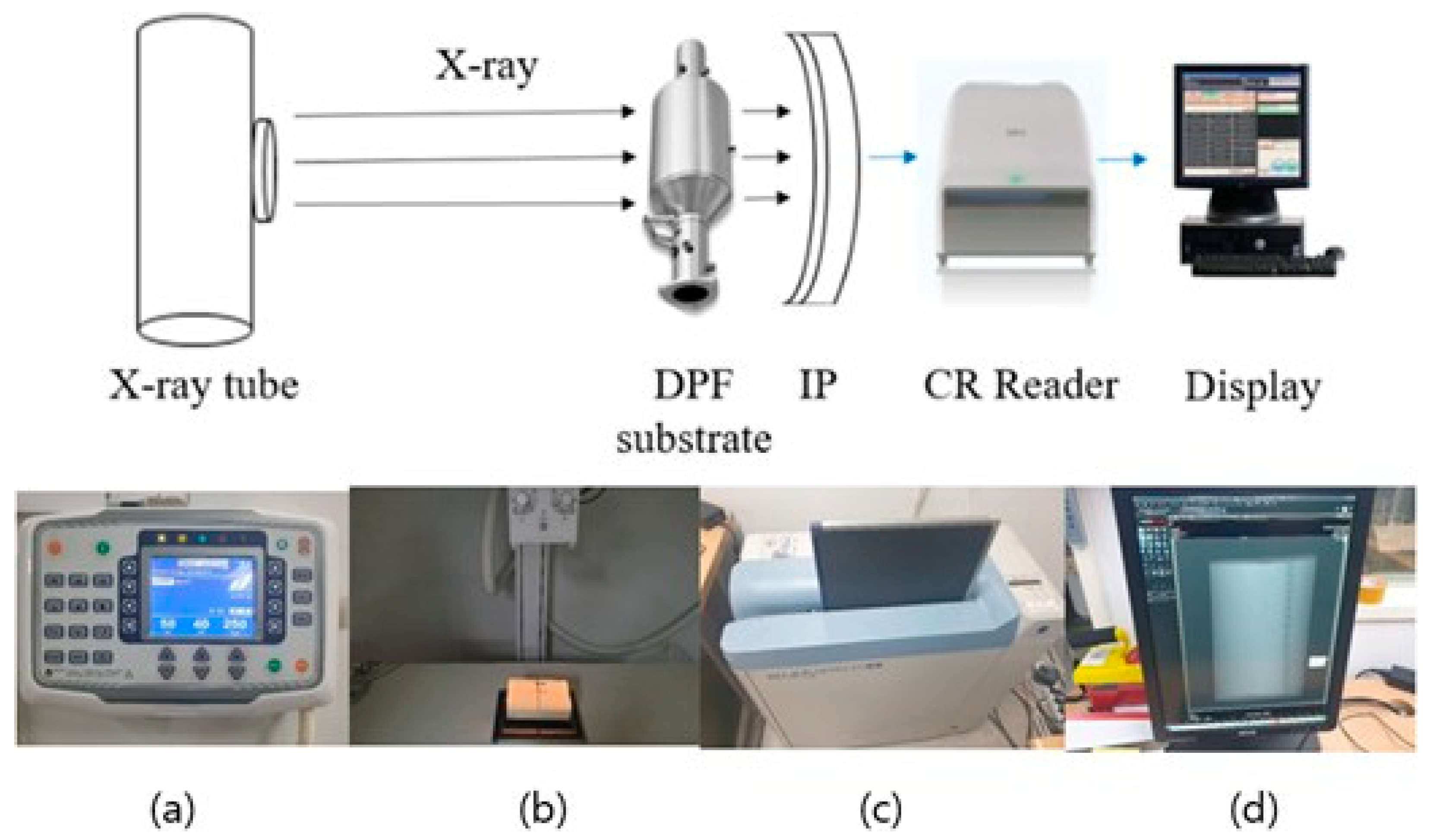
Figure 1. Photographs of CR X-ray experimental setup: (a) tube voltage and tube current settings, (b) process of X-ray imaging, (c) insertion of IP into CR reader, (d) output image displayed on computer monitor.
Applsci 13 07592 g001
Figure 2. KD-147 mode driving graph.
Applsci 13 07592 g002
Figure 3. Procedure for measurement of particle number and smoke opacity.
Applsci 13 07592 g003
Figure 4. CR X-ray images and photos of damaged DPF samples.
Applsci 13 07592 g004
Figure 5. Smoke concentration averaged over 10 repetitions of exhaust test using samples with various types of DPF damage.
Applsci 13 07592 g005
Figure 6. Average particle number in concentration measurements of normal and crack-damaged DPF samples.
Applsci 13 07592 g006
Figure 7. Average particle number in concentration measurements of DPF samples.
Applsci 13 07592 g007
Table 1. Specifications of vehicle used in this study.
Engine TypeD4EA (CRDI VGT)
Length4500 mm
Width1845 mm
Height1740 mm
Empty vehicle weight (curb weight)1745 kg
Gross vehicle weight2185 kg
Displacement1991 cc
Rated power126/4000 (PS/rpm)
Max. number of passengers7
Number of cylinders4
Type of fuelDiesel
First type exhaust emission reductionDOC: ceramic type, 400 cpsi DPF:
device (DOC + DPF)cordierite type, 200 cpsi
Table 2. KD-147 mode composition.
Warm-up modeVehicle runs at a speed of 50 ± 6.2 km/h with a load equal to 40% of the rated engine output based on the chassis power and after preheating for 40 s.
To form the inspection mode, the set load horsepower and running speed of the vehicle to be measured must be maintained according to the mode configuration requirements.
In the event of any deviation from the mode configuration requirement in the preheating mode, a restart is performed from the time at which the deviation from the mode configuration requirement occurred.
Driving modeImmediately after the warm-up mode ends and the chassis power meter roller stops, sudden acceleration and acceleration are performed while traveling from the stopped state (idle).
Table 3. Number of tests and regenerations and test conditions.
Number of regenerations for each DPFOnce (50–600 s)
Vehicle warm-up timeApproximately 10 min
Exhaust emission measurementSmoke concentration and particle number
Number of tests/
regenerations
Normal10/1
Crack10/1
Melting10/1
Hollow10/1
Plug10/1
Table 4. PN inspection system for vehicles in operation in European Union countries.
NationEffective DatePN TLVApplied Range
NetherlandsJuly 20221,000,000LD: Euro 3, 4, 5, and 6; HD: Euro 6
BelgiumJuly 20221,000,000LD: Euro 5b–6
GermanyJuly 2023250,000Diesel: LD: Euro 6; HD: Euro 6
Disclaimer/Publisher’s Note: The statements, opinions and data contained in all publications are solely those of the individual author(s) and contributor(s) and not of MDPI and/or the editor(s). MDPI and/or the editor(s) disclaim responsibility for any injury to people or property resulting from any ideas, methods, instructions or products referred to in the content.