
Research on the Safety Assessment of Corbel Beams of Reservoir Radial Gates Based on Real States
1
China Institute of Water Resources and Hydropower Research, Beijing 100038, China
2
State Key Laboratory of Simulation and Regulation of Water Cycle in River Basin, Beijing 100038, China
*
Authors to whom correspondence should be addressed.
Appl. Sci. 2023, 13(13), 7578; https://doi.org/10.3390/app13137578
Submission received: 11 April 2023
/
Revised: 18 June 2023
/
Accepted: 19 June 2023
/
Published: 27 June 2023
(This article belongs to the Special Issue Advances in Civil Structural Damage Detection and Health Monitoring)
Abstract
:The radial gate corbel beam is a kind of gate support structure more often used in large and medium-sized reservoirs, but the current corresponding structural design code does not give a review calculation method for it. Because there are obvious differences between a corbel and a corbel beam in structural form and force, if the corbel beam is just simplified in the calculation as a corbel structure, it can easily lead to misjudgment of insufficient bearing capacity. This misjudgment has a significant impact on later safety assessment, danger removal, and reinforcement. Currently, there are limited studies available on the internal stress distribution of the corbel beam. In this study, taking the danger removal and reinforcement of the radial gate beam of a medium reservoir in Beijing as an example, the concrete quality of the dam was tested by the core drilling method, and two safety review methods of the corbel beam for different types of reservoirs were proposed in combination with the Code for Design of Hydraulic Concrete Structures (SL191-2008). Then, three different types of calculation model were established by the method of theoretical mechanics calculation and finite element simulation. Combined with the safety test data, the stress state of the combined stress structure of the corbel beam and gate pier under the real state was analyzed and the safety evaluation was carried out. The calculation results of these two corbel beam safety review methods were respectively reduced by 32% and 47% compared with the current calculation method. Engineering practice has proved the rationality of the two safety evaluation methods proposed in this paper, which can provide a certain reference for similar engineering reinforcement.
1. Introduction
The radial gate is widely used in large and medium-sized hydraulic projects due to its advantages of light weight, small opening force, stable flow pattern through the gate, simple operation and maintenance, etc. It is characterized by the high pressure of support and the high positioning accuracy requirements of the support strut [1,2,3]. The commonly used supporting structure of the radial gate is the corbel, but as a typical cantilever structure, the corbel has many problems, such as many reinforcing bars, difficult construction, and difficulty to control the positioning accuracy of the support strut. In order to solve the above problems, many radial gates of large and medium-sized reservoirs adopt the corbel beam as their supporting structure, and it has performed well in operation for many years.
However, with the progress of the reservoir danger removal and reinforcement, it has been discovered that there is no corresponding safety evaluation specification for the safety evaluation of the corbel beam of the radial gate. At present, the Code for Design of Hydraulic Concrete Structures (SL191-2008) [4] is commonly used for the safety assessment of corbel beams, but due to the special spatial structure of corbel beams, which form a joint force with gate piers, their stress state is more complicated compared with that of the cantilever structure of the corbel, and their ability to bear loads and bending moments is much greater than that of the corbel structure. Therefore, directly applying the safety assessment specification of the corbel to the corbel beam may lead to an incorrect judgment of insufficient bearing capacity, thereby impacting subsequent safety assessment, danger removal, and reinforcement processes [5,6].
There are quite a few studies on the force analysis of the corbel and corbel beam structures of radial gates. Wang Weidong et al. [7] used the SAP84 program with 8-node uncoordinated units to calculate the internal forces and bending moments of the corbel beam and the overall structure of the gate pier; Zhang Fude et al. [8] used the HARMA three-dimensional structural analysis program to calculate the large differences in stress distribution inside the corbel beam and the corbel; Liu Wei et al. [9] used the method of structural mechanics to simplify the structural design of the corbel of radial gates; Yan Danqing et al. [10] used theoretical mechanics to analyze and calculate the structure of the corbel beam; He Zhi-Qi [11] et al. proposed a direct equation to quantify the load transfer law by studying the load transfer mechanism in deep beams and corbels; Dawood [12] et al. employed the shear friction method (SF) and strut and tie modeling (STM) to compare and analyze the effects of parameters such as a/d, width (b), compressive strength of concrete (f’c), yield strength of reinforcement (fy), and horizontal to vertical load ratio (H/V) on the shear capacity of a concrete cantilever beam. Dovzhenko [13] et al. analyzed three damage cases and the ultimate load calculation of concrete cantilever beams in shear; Abdul-Razzaq K S [14] et al. used the shear friction (SF) method and strut and tie modeling (STM) to compare and calculate the ultimate load capacity of concrete cantilever beams with different shear span to effective depth ratios (a/d) for the ultimate load carrying capacity.
However, the above studies mostly focus on the concrete cantilever structure, and there are no detailed analysis and research on the stress distribution of the joint force structure of the corbel beam and gate pier of the radial gate combined with engineering examples.
In order to make an accurate safety assessment of the corbel beam, a finite element simulation of the joint force structure of the corbel beam and the gate pier (hereinafter referred to as the corbel beam structure) needs to be undertaken in conjunction with the real engineering properties [15,16]. The real state of the corbel beam mainly includes the real material parameters and the force state. After years of operation, the material properties of the corbel structure will change, which will lead to changes in the internal stress state and even stress concentration. Therefore, the safety assessment of the corbel beam structure needs to be based on the safety inspection data and test data to give the model real engineering data, and the safety assessment based on the real state of internal stresses to ensure the accuracy of the assessment results.
This paper uses the safety assessment of the corbel beam in a medium-sized reservoir in Beijing as a case study. It proposes two methods for the safety assessment of corbel beams in radial gates, applicable to small-scale reservoirs, and large and medium-scale reservoirs, respectively, in accordance with the Code for Design of Hydraulic Concrete Structures (SL191-2008). Additionally, the paper establishes three models by integrating theoretical mechanics and finite element simulation to analyze the stress in the joint force structure of the corbel beam and gate pier, considering the real state. The safety assessment of the corbel beam structure is combined with the field inspection data and safety review results, which provides a solid basis for the safety assessment and repair and reinforcement of this project later. In the reservoir safety assessment project in China, the method proposed in this paper makes up for the gap in the safety review specification of corbel beams, and provides a complete corbel safety review process, which can provide a theoretical basis for the safety assessment of corbel beams in similar projects [17,18,19].
2. Corbel Beam Structural Quality Inspection and Analysis
2.1. Project Overview
This study takes a medium-sized reservoir in Beijing as an example of the danger removal and reinforcement project. This reservoir was completed in 1981, and the main project is a hyperbolic concrete arch dam, including the overflow dam section and non-overflow dam section, with a total length of 90.75 m, top width of 3.0 m, bottom width of 14 m, center angle of 66~120°, maximum dam height of 70.00 m, top elevation of 624.00 m, and top elevation of wave wall 625.20 m. There are five overflow holes at the top of the dam, one diversion pipe, one irrigation pipe, one sand drainage hole each at the lower part of the dam, and one grouting corridor inside the dam.
The concrete design index of the dam body, overflow surface, gate pier, and working bridge is C2820. The dam foundation is located on the thin layer of dolomitic limestone in the Wumishan Formation of the Sinian Period, with a seismic grade of 8. There are a few intercalated mud layers distributed in the rock body about 5 m below the contact surface of concrete and bedrock, and corrugated laminae are developed.
The overall view of the downstream of this hyperbolic arch dam is shown in Figure 1.
The outlet entrance is located at the bottom of the dam, comprising a 2 × 2 m square hole, and the gate is a radial gate, with specifications of 2 × 1.7–51.55 m, as shown in Figure 2. The engineering grade is Ⅲ, the main building level is 3, and the secondary building level is 4.
The base information of the concrete design strength index, section size and upstream head is shown in Table 1.
2.2. Concrete Quality Inspection of the Corbel Beam Structure
To accurately analyze the real working state and stress distribution of the corbel beam structure, a detailed inspection and analysis of its concrete quality after years of operation is required. Concrete strength is an important parameter to measure the quality of concrete, and the measurement of concrete strength can provide a reliable basis to accurately evaluate the safety of the corbel beam structure [20,21,22,23]. This project uses core drilling for concrete strength testing, which has the advantages of being direct, reliable, and accurate.
A total of 11 concrete core samples with a diameter of Φ150 mm were drilled at the dam body, including 1 at the upstream face, 1 at the top of the dam and 9 at the downstream face, and a total of 21 core samples were used for the compressive strength testing. The core samples had dense concrete, uniform aggregate, good appearance quality, and no internal defects, as shown in Figure 3.
2.3. Concrete Quality Inspection Results and Analysis of Corbel Beam Structure
A total of 21 core specimens were tested to determine the strength of the concrete dam; the test pictures are shown in Figure 4 and the test results are shown in Table 2. The minimum compressive strength value was 26.2 MPa and the maximum value was 55.4 MPa. According to the relevant specifications of the Technical Regulations for Testing Concrete Strength by Core Drilling Method (CECS 03-2017) [24], abnormal data are removed, and reasonable data are processed according to the table coefficients. The upper and lower limits of the presumed strength range are 33.6 MPa and 26.7 MPa.
The static compressive elastic modulus of the concrete test was determined in accordance with the Test Code for Hydraulic Concrete (SL352-2020) [25] in the test protocol for the downstream face of the dam, the upstream face, and the top part of the core; each core sample was processed into a specimen with dimensions of Φ150 × 300 mm. Six sets of tests were conducted, as shown in Figure 5.
The static compressive modulus of elasticity takes the tangent of the stress from 0.5 MPa to 40% of the failure stress, and the calculation formula is shown in Formula (1):
where:
- —Static compressive elastic modulus, GPa;
- —Stress increase value from 0.5 MPa to 40% failure stress, MPa;
- —The strain increase value from the corresponding strain of 0.5 MPa to the corresponding strain of 40% failure stress.
In the formula, stress and strain are calculated according to Formulas (2) and (3):
where:
- —load, kN;
- —The bearing area of the test piece, mm2;
- —deformation value, mm;
- —Measuring the deformed gauge length, mm.
The elastic modulus tangents of the six groups of tests are shown in Figure 6. In Figure 6, the horizontal axis is the strain value in the range from 0.5 MPa to 40% failure stress, and the vertical axis is the corresponding stress value. The results are shown in Table 3.
The test results reveal that the minimum value of the static compressive elastic modulus of the dam concrete is 39.4 GPa, the maximum value is 54.1 GPa, and the average value is 47.1 GPa.
Based on the results of the core method test, it is clear that the mechanical properties of concrete in this reservoir have been improved compared to the design values after more than 40 years of operation, reaching the strength standard of C30 concrete, and the dam concrete is of excellent quality. This may be due to the better temperature and humidity conditions inside the concrete, resulting in a slow growth of the compressive strength as the concrete ages [26,27].
3. Finite Element Simulation and Safety Review of the Corbel Beam of the Radial Gate
3.1. Load Calculation
At the normal storage level, the water pressure acting on the radial gate is transmitted to the corbel beam through the supporting strut. According to Table 1, the hydrostatic pressure at the normal storage level is Px = 1783.6 kN in the horizontal direction and Py = 946.9 kN in the vertical direction. Therefore, the stress transmitted by the strut can be regarded as a thrust force of 2019.37 kN with an angle of 30.42° in the horizontal direction, and as a uniform stress distributed in two 60 × 60 mm regions on the corbel beam, as shown in Figure 7.
3.2. Structural Safety Review Methods for Corbel Beams
Because of the cantilever structure of the corbel, its spatial stress state differs greatly from that of the corbel beam, and the joint bearing structure formed by the corbel beam and the gate pier has a load-bearing capacity that is much larger than that of the cantilever structure. Thus, it is necessary to improve the code for review of the corbel in the Code for Design of Hydraulic Concrete Structures (SL191-2008) to enable its use in the safety assessment of the corbel beam.
To use the radial gate corbel beam of the gate pier local tension area crack control test as an example, its crack control should meet the requirements of Formula (4).
When the gate pier is thrust by one side of the radial gate support:
where Fk—calculated by the standard value of the load on the gate pier side of the radial gate support thrust value (N); b—radial gate support width (mm); B—thickness of the gate pier (mm); —distance between thrust force of radial gate support and the center line of gate pier thickness (N); standard value of concrete axial tensile strength (N/mm2).
According to the specification, this review formula is derived from the model test. Under the thrust exerted on one side of the gate pier near the radial gate support, cracks appear perpendicular to the thrust direction at the junction of the support and the gate pier, and develop along the thickness direction of the gate pier. The corbel crack resistance is related to the concrete tensile strength, the relative position of the support in the gate pier, the effective distribution width of the support, the thickness of the gate pier, and the stress state under different thrusts. Therefore, based on the safety review specification of the corbel, this paper proposes two kinds of safety assessment methods for corbel beams applicable to different types of reservoirs and conducts the comparative analysis.
- (1)
- Safety assessment by theoretical mechanics method
The corbel crack resistance is related to the concrete tensile strength, the effective distribution width of the support, and other factors, but according to the principle of safety assessment, we can presume that the bending moment at the junction of the corbel beam and gate pier has the greatest influence on the crack control in the local tensile area of the gate pier. Therefore, we calculate the equivalent coefficient a according to the ratio of the bending moment at the fixed end of the corbel beam gate pier and the bending moment of the corbel in this section, and then include it in Formula (4) for calculation [28,29,30]. This method is simple and suitable for the safety assessment of the corbel beam of the curved gate of small projects with simple force conditions.
- (2)
- Structural safety assessment of corbel beams by finite element simulation based on real state
Method (2) is based on the safety inspection and test data for finite element simulation, analyzing the stress distribution state of the corbel beam structure under the real state, finding out the dangerous area of its stress concentration, and assessing the working state of the corbel beam structure in combination with the field inspection. Then, the shear force of the corbel beam structure subjected to the center point of the radial gate support thrust at the cross-section is calculated and brought into equation (4) for calculation [31,32,33]. Finally, considering the field test data, simulation results analysis, and review calculation results, an accurate safety assessment of the corbel beam structure is made. This method is applicable to the safety review of the corbel beam of medium and large-scale reservoir radial gates with complex force conditions.
3.3. Computational Model
Based on the two safety review methods proposed in the previous section, this paper utilizes three models for calculation and analysis. Model 1 and model 2 are the theoretical mechanical models of the corbel and corbel beam, and model 3 is the finite element simulation model of the joint force structure of the corbel beam and the gate pier under the real state.
① Theoretical mechanical model of the corbel.
The corbel beam is considered as a protrusion from the fixed end of the side pier for calculation purposes, with a disconnect at the middle. The length of the bull leg is 1.5 m.
According to Table 1, the horizontal hydrostatic pressure Px = 1783.6 kN, vertical hydrostatic pressure Py = 946.9 kN, and the self-weight of the corbel beam is 44.1 kN. In the theoretical mechanical model, its force is simplified to a thrust of 1998.62 kN at an angle of 26.82° in the horizontal direction, i.e., the unilateral support strand strut F = 999.31 kN, and the eccentricity is taken as the distance from the middle point of the supporting strut to the middle point of the gate pier b = 950 mm.
The force sketch is shown in Figure 8.
The formula for calculating the bending moment is shown in Equation (5).
where:
- —The thrust force acting on the corbel, F = 999.31 kN;
- —The distance between the force point and the edge, = 950 mm.
② Theoretical mechanical model of corbel beam.
The length of the corbel beam is taken as the distance between the midpoint of the gate pier on both sides, L = 3000 mm, and the force is the same as the theoretical mechanical model of the corbel, i.e., it is subjected to two support winch thrusts at 950 mm from the midpoint of the gate pier on both sides, F = 999.31 kN.
The mechanics model is shown in Figure 9.
The formula for calculating the fixed end bending moment is shown in Equation (6):
where:
- —The thrust force acting on the corbel beam, F = 999.31 kN.
- —The distance between the force point and the midpoint of the gate pier on both sides, = 950 mm.
- = /, is the distance between the midpoint of the gate pier on both sides, = 3000 mm.
③ Finite element simulation of the joint force structure of the corbel beam and gate pier in the real state.
The thickness of the gate pier in this model is 1 m, and the three dimensions of the corbel beam are 0.8 × 1.2 × 2 m. Considering that the corbel beam and the gate pier constitute a common force structure in the actual project, the gate pier in the 4 × 6 m area near the corbel beam is modeled using finite element simulation, and the stress transmitted from the support strut is regarded as a thrust force of 2019.37 kN at an angle of 30.42° to the horizontal direction, which is uniformly distributed in two 60 × 60 mm areas on the corbel beam. Furthermore, the corbel beam is connected to the edge of the gate pier by means of a fixed end. The mechanical parameters of the concrete are taken from the results of the core drilling test, assuming it is an isotropic material, and the density is taken as 2300 kg/m3, the static modulus of elasticity is taken as 47.1 GPa, Poisson’s ratio is taken as 0.18, the compressive strength is taken as 31.2 MPa, and the temperature is 22 °C. The finite element meshes are mainly regular hexahedrons. Considering that the mesh size and number may have an impact on the calculation results, the mesh sizes of 0.02, 0.04, 0.08, 0.1, 0.15, 0.2, and 0.5 were used for calculation, and it was found that the calculation results were basically consistent when the mesh size was less than 0.2 m. Therefore, under the premise of taking into account the calculation speed and calculation accuracy, the overall mesh size was adjusted to 0.08 m, the mesh at the junction of the corbel beam and the pier was encrypted, and the size was adjusted to 0.04 m. The model consists of 1,152,722 nodes and 827,374 elements in total [34,35,36,37,38].
The modeling is shown in Figure 10.
3.4. Analysis of Calculation Results and Safety Review
- (1)
- Safety assessment by theoretical mechanics method
Through theoretical calculation, it can be seen that the bending moment at the fixed end of the corbel in model 1 is M = 949.34 kN.m; the bending moment at the fixed end of the corbel beam in model 2 is M = 648.72 kN.m. This is because the corbel beam forms a joint force structure with the gate pier, and its internal bending moment is much smaller than that of the corbel cantilever structure. Thus, its ability to bear the supporting force and other loads is much higher than that of the corbel. Therefore, the equivalent coefficient a = 648.72/949.34 = 0.68 can be derived from the fixed end bending moment of model 1 and model 2, and brought into Formula (4) for calculation.
The calculation process and results are shown in Table 4. In Table 4, /(/) represents the maximum allowable stress, and the safety of the project is determined according to the comparison between the actual stress and this stress.
Based on the safety review of the structure, it is evident that the corbel beam structure is in normal working condition and does not require any danger removal or reinforcement.
Due to the simple structure of the radial gate corbel beam of small projects, the effect of stress concentration is not obvious, and this method can be directly used for safety review under the premise that no obvious defects are found in the field inspection, which provides the theoretical basis for the next step of the project to de-risk and strengthen.
- (2)
- Structural safety assessment of corbel beams by finite element simulation based on real states
The stress state of the joint stressed structure of the corbel beam and gate pier under the real state is more complicated. In addition to the changes in concrete material parameters and stress state, it is also necessary to consider the internal stresses generated by the extrusion and deformation of concrete under the action of self-weight and the support strut thrust. For reinforced concrete, we use the maximum tensile stress to analyze its stress hazard region [39,40].
Subsequently, detailed post-processing of the equivalent force diagrams for the corbel beam and the gate pier was conducted, as shown in Figure 11.
From Figure 11, it can be seen that the corbel beam forms a stress concentration at the connection of the gate pier under the action of the support strut thrust and self-weight, and the stress state is symmetrically distributed along the midpoint of the corbel beam. For the gate pier, the stress in the area connecting with the beam is relatively large, and the stress concentration area is mainly in the first half of the thrust side of the beam. For the gate pier, the stress in the area connecting with the beam is relatively large, and the stress concentration area is mainly in the first half of the thrust side of the beam. The remaining portion of the gate pier is solely influenced by gravity, resulting in an even distribution of stress and no safety risk associated with stress concentration.
It should be noted that the probe annotation shows that the most dangerous part of the joint stressed structure of the corbel beam and gate pier in this project is at the midpoint of the connection part of the gate pier where the corbel beam is subject to the support strut thrust surface. Once the cracks appear here, deep cracks may be generated with the stress concentration, thus affecting the safety of the overall structure. Combined with the site inspection, the surface of the corbel beam structure appears intact, with no signs of reinforcement corrosion or cracks and defects in the stress concentration area. Thus, the working condition of the corbel beam structure can be judged to be normal.
Then, the corbel beam structure was reviewed for safety, and the nodal force at the cross-section (950 mm from the midpoint of the gate pier) where the corbel beam was subjected to the center point of the support strut thrust was calculated, and then the shear force was calculated by integration, as shown in Table 5.
Then the shear force is brought into Equation (4) for calculation, and the calculation process and results are shown in Table 6.
Finally, considering the site inspection data, the stress analysis of finite element simulation, and the results of the review calculation, the surface of the corbel beam structure of this reservoir is intact, no corrosion of reinforcement has occurred, no cracks are found in the stress concentration area, and the results of review calculation are in accordance with the specification, so it can be judged that the corbel beam structure of this reservoir has good engineering quality and operates normally, and there is no need to carry out danger removal and reinforcement.
Method (2) requires experimental analysis of the concrete performance of the corbel beam structure, finite element simulation to be carried out based on the experimental data, the stress distribution to be analyzed under the real state, and then the review calculation to be carried out. The process is more complicated, but the real working state of the corbel beam structure can be accurately evaluated, and then the targeted danger removal and reinforcement can be carried out, which is suitable for the safety assessment of large and medium-scale reservoirs with a complex stress state.
The current calculation method for the corbel beam safety review is to disconnect the corbel beam from the middle and treat it as a corbel for review calculation. Therefore, the calculation results of the current method are compared with the two methods proposed in this paper, as shown in Figure 12:
Figure 12 illustrates that method (1) yields a calculation result 32% lower than that of the current method, while method (2) yields a result 47% lower than that of the current method. Furthermore, the current method exceeds the safety limit. This discrepancy demonstrates that the combined force structure of the corbel beam and gate pier possesses significantly higher load-bearing capacity than the corbel’s cantilever structure. If the calculation is performed using the current method, it may lead to a misjudgment that the project fails to meet the safety assessment specifications, which will affect the danger removal and reinforcement.
The safety inspection information shows that this reservoir sand discharge vent has good appearance quality after more than 40 years of operation, no cracks or concrete breakage are evident, and the strength meets the requirements. The operation conditions are consistent with the evaluation results, which proves that the two safety evaluation methods for corbel beam structures proposed above are in line with actual projects, and can be used in safety evaluation to replace the current review method, providing a theoretical basis for the reinforcement of similar projects.
4. Conclusions
Concrete corbel beams are extensively employed as support structures for radial gates in large and medium-sized reservoirs. However, it has been observed that the current design code in China lacks an appropriate safety assessment method for corbel beams of radial gates. Utilizing the corbel assessment method in this context may lead to misjudgments regarding the working condition of corbel beams, consequently impacting subsequent safety assessments and danger removal and reinforcement.
Therefore, in order to make an accurate safety assessment of the corbel beam, this paper takes the corbel beam reinforcement project of a medium-sized reservoir radial gate in Beijing as an example. Through on-site inspection and a core drilling test, the results show that the concrete strength is good, and it has been improved compared with the design value. Then, combined with the Code for Design of Hydraulic Concrete Structures (SL191-2008), the theoretical mechanical safety assessment method applied to small-scale projects and the finite element simulation safety assessment method applied to large and medium-scale projects were proposed, and three calculation models were established with the safety inspection test data. Through the calculation results of the three models, the stress distribution of the corbel and the joint stress structure of the corbel beam and gate pier were compared and analyzed, and finally, combined with the field inspection test data, stress distribution analysis, and safety review results, it was judged that the working state of the corbel beam structure of this project is normal and the operation meets the design requirements. The current safety assessment method and the calculation results of the two methods proposed in this paper were then compared and analyzed, thereby proving the rationality of the corbel beam safety assessment method proposed in this paper. These methods can be used to replace the current calculation method for safety assessment and provide a theoretical basis for the removal of dangers and reinforcement of similar projects.
Since the corbel safety assessment method proposed in this paper is based on the inadequacies of existing codes, it is used to make up for the lack of a theoretical basis for corbel beam safety review in actual engineering. Therefore, as relevant research progresses and relevant specifications improve, further analysis and research can be conducted on the stress distribution of corbel beams, taking into account water level changes and concrete aging damage models. This will enable the formulation of more comprehensive safety assessment specifications for widespread adoption and application.
Author Contributions
Conceptualization, R.W.; methodology, J.L., Y.Z. and Y.S.; validation, R.W., J.L., Y.Z. and Y.S.; data curation, R.W.; writing—original draft preparation, J.L.; writing—review and editing, R.W., Y.Z. and Y.S.; visualization, J.L., Y.Z. and Y.S.; supervision, R.W. All authors have read and agreed to the published version of the manuscript.
Funding
This research was funded by National Key R&D Program of China (No. 2022YFC3005503), the IWHR Basic Research Fund (No. SM0145B022021), Scientific research project of Yangtze River and Huai River (No. HNYJJH/JS/FWKY-2021005).
Institutional Review Board Statement
Not applicable.
Informed Consent Statement
Not applicable.
Data Availability Statement
Not applicable.
Acknowledgments
The authors would like to thank Mengmeng Zhang and Lang Yu for providing experimental equipment and experimental data support.
Conflicts of Interest
The authors declare no conflict of interest.
References
- Wang, Y.L.; Jin, Y.G.; Chen, X.L.; Duan, Q.C.; Zhang, Z.; Lei, X.H.; Chang, W.J. Comparison of LSTM neural network and gauge analysis method in overflow calculation of radial gates. S. N. Water Divers. Water Conserv. Sci. Technol. 2022, 20, 590–599. (In English) [Google Scholar]
- Yang, S.; Tao, G.H.; Qin, Z.Q.; He, W.; Li, Y.F. Static characteristics of table hole radial gate support arm and its supporting structure based on ANSYS. Water Sci. Cold Zone Eng. 2022, 5, 32–34. [Google Scholar]
- Zhang, B.Z.; Jing, X.C. Theoretical analysis and simulation calculation of hydrodynamic pressure pulsation effect and flow induced vibration response of radial gate structure. Sci. Rep. 2022, 12, 21932. [Google Scholar] [CrossRef]
- SL191-2008[S].2008; Code for the Design of Hydraulic Concrete Structures. Ministry of Water Resources: Beijing, China, 2008.
- Abdul-Razzaq, K.S.; Dawood, A.A.; Mohammed, A.H. A Review of Previous Studies on the Reinforced Concrete Corbels. IOP Conf. Ser. Mater. Sci. Eng. 2019, 518, 022057. [Google Scholar] [CrossRef]
- Madhkhan, M.; Bahrami, S. Performance of the modified precast beam to column connection placed on a concrete corbel. Civ. Eng. Infrastruct. J. 2019, 52, 365–377. [Google Scholar]
- Wang, W.D.; Meng, Z.G.; Zhang, Q. The rationality of using corbel support beam in deep-hole radial gates of large and medium-sized reservoirs. Shanxi Water Conserv. Sci. Technol. 1995, 73–76+80. [Google Scholar]
- Zhang, F.D.; Sun, H.J.; Liao, L.B. Spatial force analysis of corbel beam structure of gate pier. In Proceedings of the Sixth National Academic Conference on Structural Engineering; 1997; Volume 2, pp. 468–471. [Google Scholar]
- Liu, W.; Xu, S.H.; Chen, J. Discussion on the design of corbel of radial gate. Heilongjiang Water J. 2002, 42–43. [Google Scholar]
- Yan, D.Q.; Zhang, R. Simplified calculation of corbel beam structure of gate pier. Haihe Water Resour. 2015, 64–66. [Google Scholar]
- He, Z.Q.; Liu, Z.; Ma, Z.J. Investigation of load-transfer mechanisms in deep beams and corbels. ACI Struct. J. 2012, 109, 467–476. [Google Scholar]
- Dawood, A.A.; Kadhum, A.K.; Abdul-Razzaq, K.S. Strength of reinforced concrete corbels-a parametric study. Int. J. Civ. Eng. Technol. IJCIET 2018, 9, 2274–2288. [Google Scholar]
- Dovzhenko, O.; Pohribnyi, V.; Pents, V.; Mariukha, D. Bearing capacity calculation of reinforced concrete corbels under the shear action. MATEC Web Conf. 2018, 230, 02005. [Google Scholar] [CrossRef]
- Abdul-Razzaq, K.S.; Dawood, A.A. Corbel strut and tie modeling-Experimental verification. Structures 2020, 26, 327–339. [Google Scholar] [CrossRef]
- Zhang, G.X. Research on the Real Working State of High Arch Dams and Engineering Applications; China Institute of Water Resources and Hydropower Research: Beijing, China, 2013. [Google Scholar]
- Liu, Y. Study on the Factors Influencing the Real Working State of High Arch Dams; China Institute of Water Resources and Hydropower Research: Beijing, China, 2007. [Google Scholar]
- Chen, S.; Gu, C.; Lin, C.; Hariri-Ardebili, M.A. Prediction of arch dam deformation via correlated multi-target stacking. Appl. Math. Model. 2021, 91, 1175–1193. [Google Scholar] [CrossRef]
- Zhang, M.Z.; Pan, J.W.; Wang, J.T.; Chi, F.D. Temperature field inversion and stress simulation analysis of Xiaowan arch dam during operation. S. N. Water Divers. Water Conserv. Sci. Technol. 2021, 19, 786–794+813. (In English) [Google Scholar] [CrossRef]
- Liu, Y.; Gao, Y.Q.; Zhang, G.X.; Zhang, L.; Duan, S.H.; Zhang, J. Simulation and inversion analysis of the working properties of Jinping Grade I extra-high arch dam. Water Resour. Hydropower Technol. 2017, 48, 46–51. [Google Scholar] [CrossRef]
- Huang, Y.Y.; Xie, T.; Xu, Y.; Wang, R.L. Evaluation of the mechanical parameters of a reinforced concrete dam based on multi-source data. Struct. Concr. 2022, 23, 652–668. [Google Scholar]
- Ji, Q.W.; Wen, Y.J.; Wang, S.W. Experimental study on strength and permeability of plastic concrete contaminated with lead. People’s Chang. 2022, 53, 158–162+169. [Google Scholar] [CrossRef]
- Saleh, E.; Tarawneh, A.; Dwairi, H.; AlHamaydeh, M. Guide to non-destructive concrete strength assessment: Homogeneity tests and sampling plans. J. Build. Eng. 2022, 49, 104047. [Google Scholar] [CrossRef]
- Lapidus, A.; Bidov, T.; Khubaev, A. The study of the calibration dependences used when testing the concrete strength by nondestructive methods. MATEC Web EDP Sci. 2017, 117, 00094. [Google Scholar] [CrossRef] [Green Version]
- CECS 03-2017[S].2017; Technical Specification for Testing Concrete Strength by Drilling Core Method. China Association for Engineering Construction Standardization: Beijing, China, 2017.
- SL352-2020[S].2020; Test Procedure for Hydraulic Concrete. Ministry of Water Resources of the People’s Republi of China: Beijing, China, 2020.
- Pourbaba, M.; Asefi, E.; Sadaghian, H.; Mirmiran, A. Effect of age on the compressive strength of ultra-high-performance fiber-reinforced concrete. Constr. Build. Mater. 2018, 175, 402–410. [Google Scholar] [CrossRef]
- Conrad, M.; Aufleger, M.; Malkawi, A.I.H. Investigations on the modulus of elasticity of young RCC. In Roller Compacted Concrete Dams; Routledge: Abingdon-on-Thames, UK, 2018; pp. 729–733. [Google Scholar]
- Jin, L.Z.; He, L.; Wu, X.K. Experimental study on flexural performance of HRB500 grade reinforced reactive powder concrete beams. Build. Struct. 2015, 45, 87–92. [Google Scholar] [CrossRef]
- Jing, H. Practical calculation procedures for concrete bending members—Calculation of bending moment, crack width and crack width limit control. Build. Des. Manag. 2009, 26, 31–35. [Google Scholar]
- Pratama, M.M.A.; Suhud, R.K.; Puspitasari, P.; Kusuma, F.I.; Putra, A.B.N.R. Finite element analysis of the bending moment-curvature of the double-layered graded concrete beam. IOP Conf. Ser. Mater. Sci. Eng. 2019, 494, 012064. [Google Scholar] [CrossRef]
- Lu, C.C.; Fan, W.J.; Rui, Y.Q. Study on the factors influencing the load bearing capacity of reinforced concrete beams based on ABAQUS. In Proceedings of the 2022 Industrial Building Academic Exchange Conference; 2022; pp. 357–362+239. [Google Scholar]
- Armaghani, D.J.; Hatzigeorgiou, G.D.; Karamani, C.; Skentou, A.; Zoumpoulaki, I.; Asteris, P.G. Soft computing-based techniques for concrete beams shear strength. Procedia Struct. Integr. 2019, 17, 924–933. [Google Scholar] [CrossRef]
- Marí, A.; Bairán, J.; Cladera, A.; Oller, E.; Ribas, C. Shear-flexural strength mechanical model for the design and assessment of reinforced concrete beams. Struct. Infrastruct. Eng. 2015, 11, 1399–1419. [Google Scholar] [CrossRef]
- Feng, D.C.; Wu, G.; Lu, Y. Finite element modelling approach for precast reinforced concrete beam-to-column connections under cyclic loading. Eng. Struct. 2018, 174, 49–66. [Google Scholar]
- Wei, Z.P.; Wang, H.T.; Liu, Y.; Meng, P.; Qi, Z.P. Hydraulic Performance Analysis of Turbine Based on ANSYS Finite Element Calculation Platform. Hydropower Energy Sci. 2022, 40, 199–202+54. [Google Scholar]
- Earij, A.; Alfano, G.; Cashell, K.; Zhou, X. Nonlinear three-dimensional finite-element modelling of reinforced- concrete beams: Computational challenges and experimental validation. Eng. Fail. Anal. 2017, 82, 92–115. [Google Scholar] [CrossRef]
- Hua, M.; Li, T.C. Research on early warning indicators for monitoring uneven settlement of sluice gate foundations based on three-dimensional finite element simulation. Water Resour. Hydropower Technol. 2022, 53 (Suppl. S1), 282–290. (In English) [Google Scholar]
- Su, C.; Niu, X.X.; Yin, X.M.; Yin, C. Effects of different loading methods on structural stresses in sluice gate renovation projects. Hydropower Energy Sci. 2014, 32, 95–98. [Google Scholar]
- Kolupaev, V.A. Equivalent Stress Concept for Limit State Analysis; Springer: Darmstad, Germany, 2018. [Google Scholar]
- Mei, H.; Kiousis, P.D.; Ehsani, M.R.; Saadatmanesh, H. Confinement effects on high-strength concrete. Struct. J. 2001, 98, 548–553. [Google Scholar]
Figure 1.
Overall view of the hyperbolic arch dam.
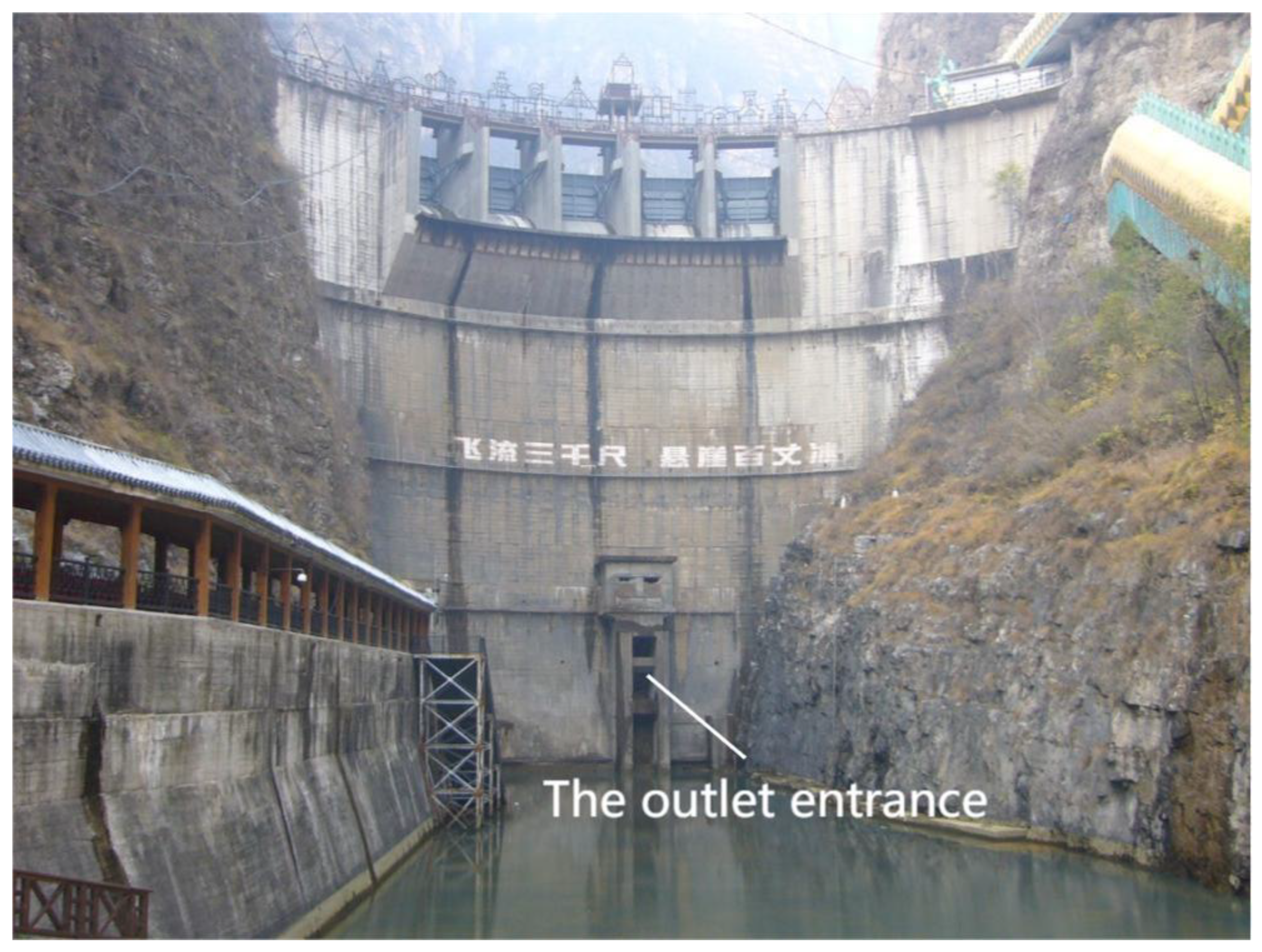
Figure 2.
Sketch of the structure of the corbel beam of the outlet entrance.
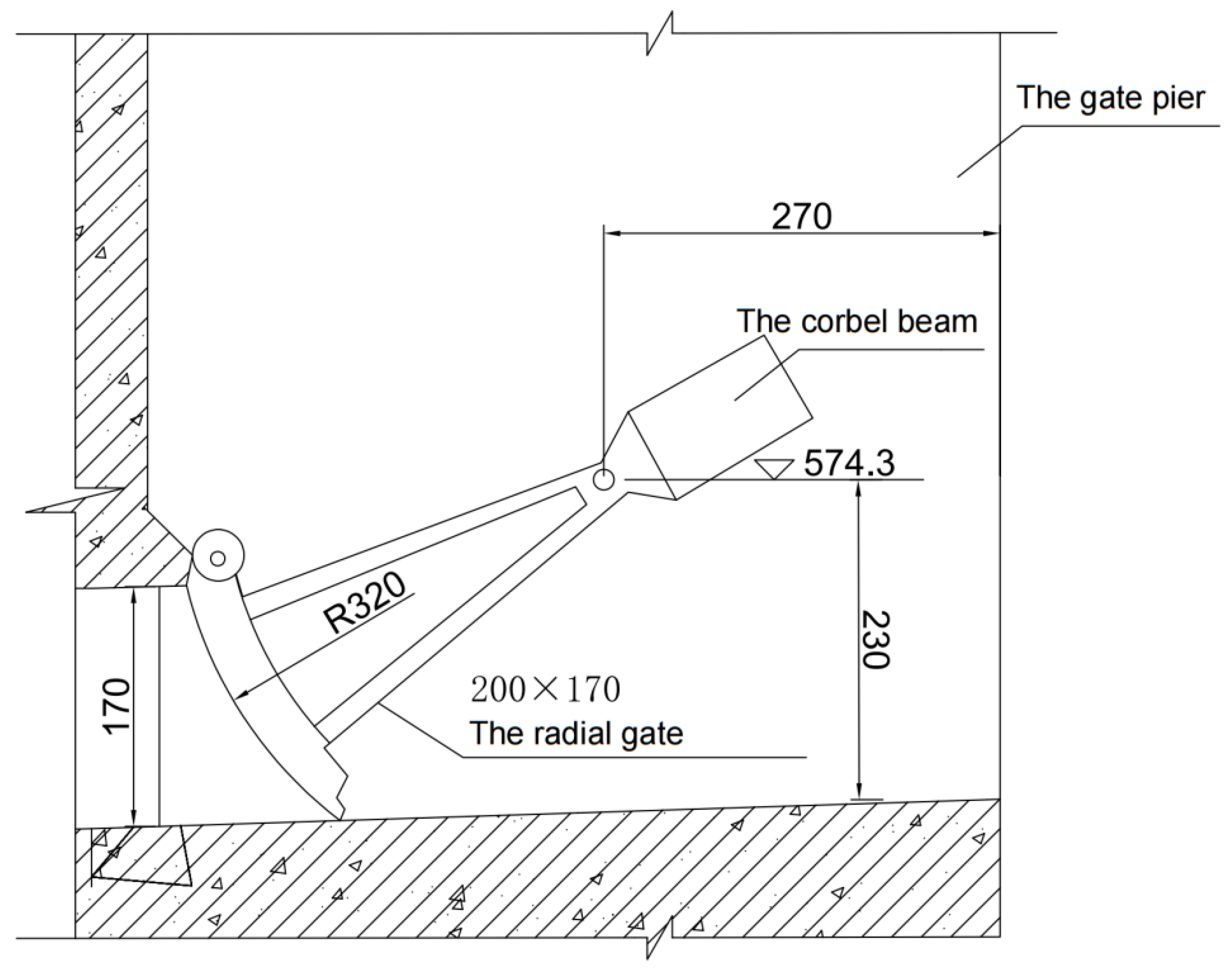
Figure 3.
Illustration of on-site core sampling.
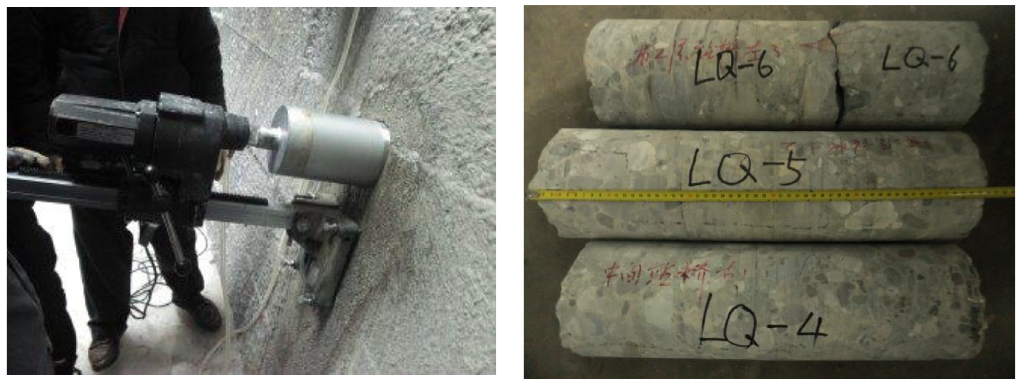
Figure 4.
Core testing of concrete strength.
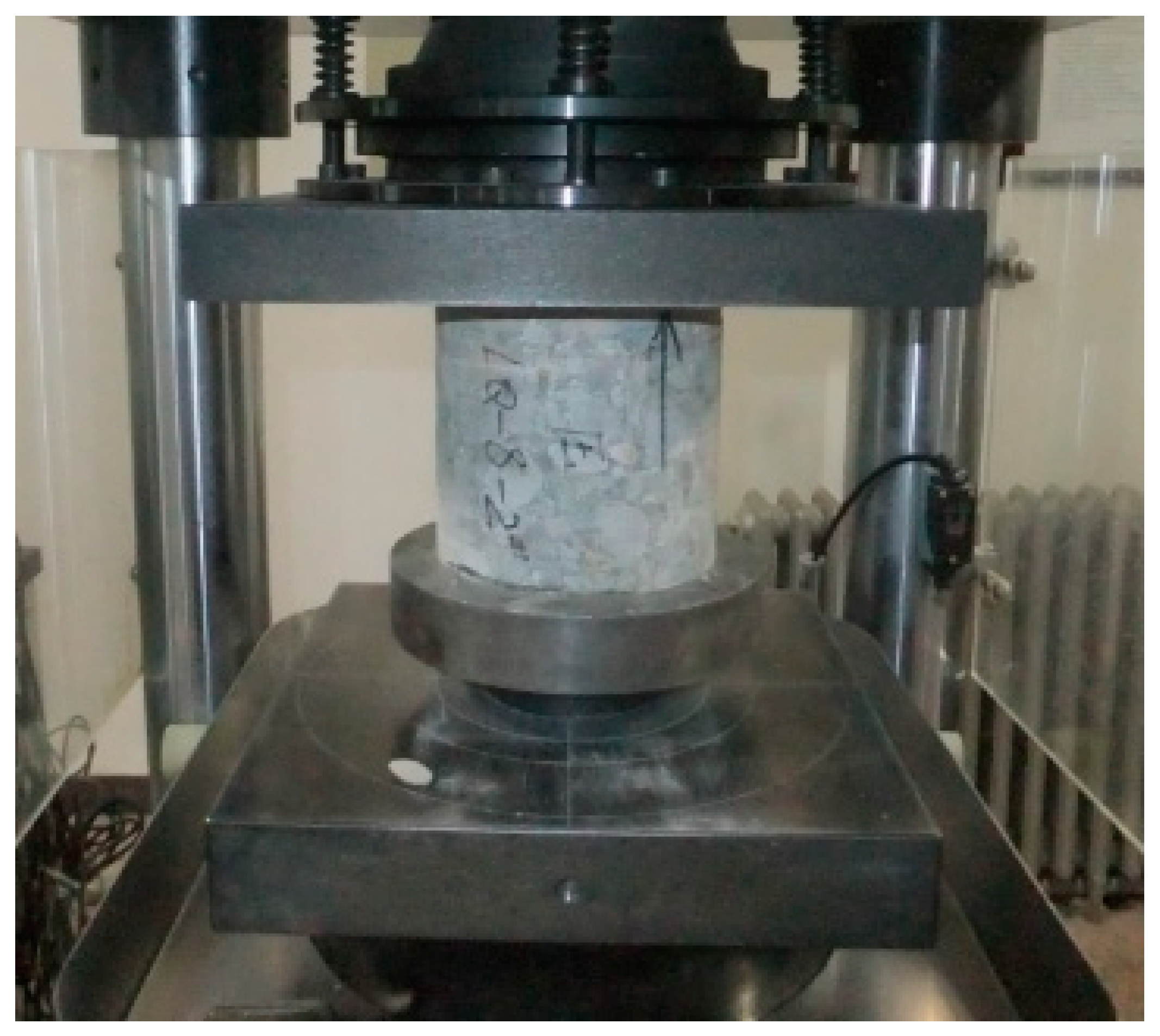
Figure 5.
Static compressive elastic modulus test.

Figure 6.
The elastic modulus tangents test data. (a) The elastic modulus tangents of LQ-2-1. (b) The elastic modulus tangents of LQ-6. (c) The elastic modulus tangents of LQ-9. (d) The elastic modulus tangents of LQ-10. (e) The elastic modulus tangents of LQ-11-2. (f) The elastic modulus tangents of LQ-11-3.
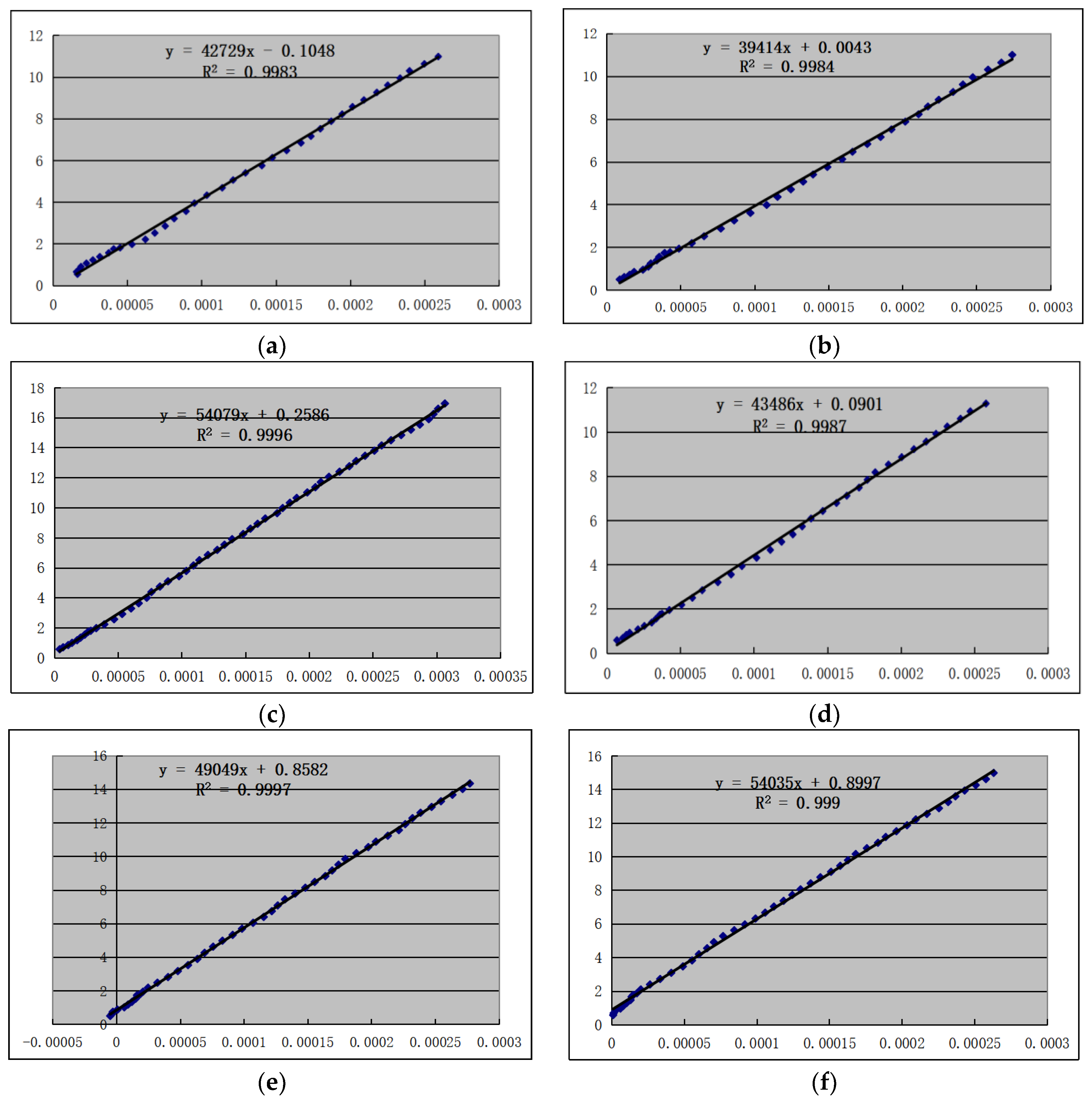
Figure 7.
Schematic diagram of the force on the corbel beam of the outlet entrance.
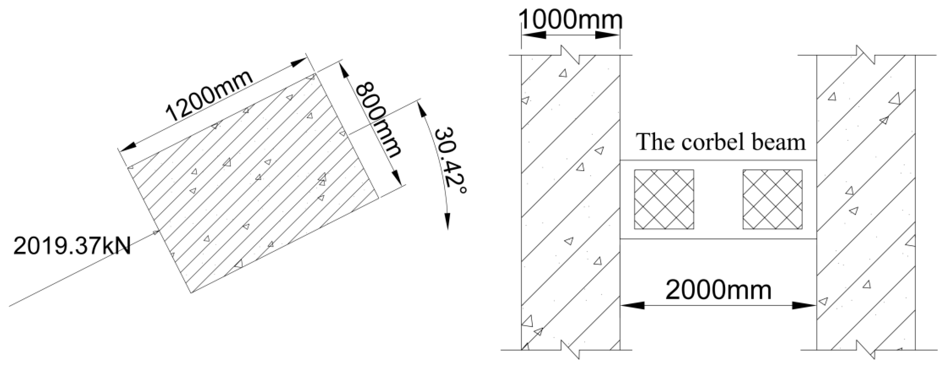
Figure 8.
Schematic diagram of the force on the corbel model.
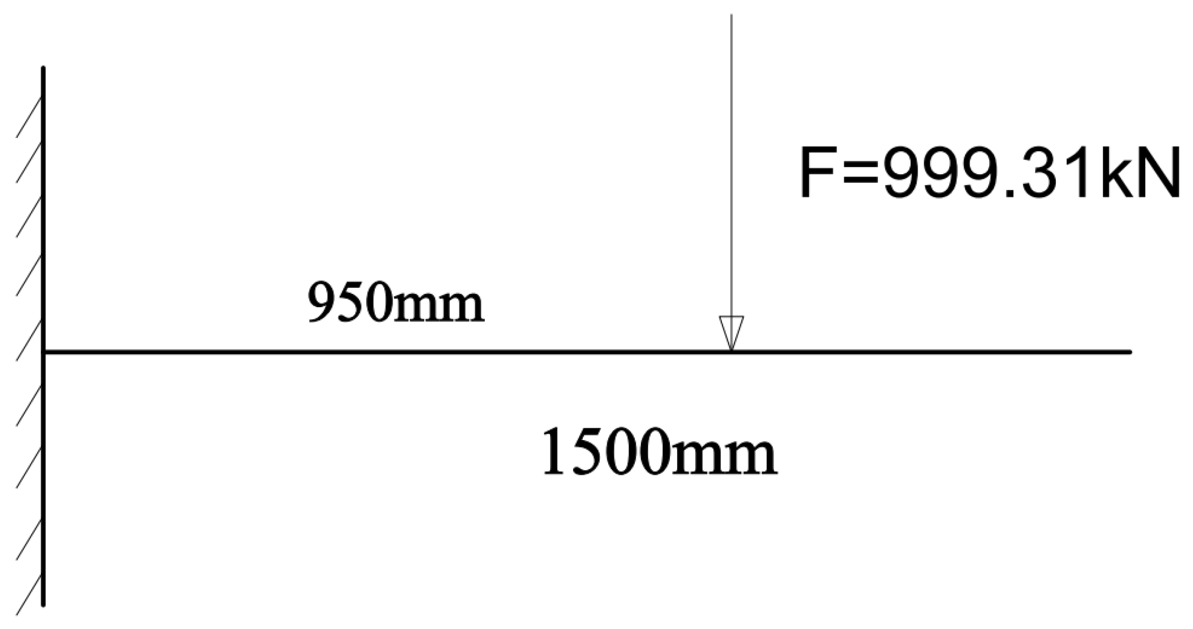
Figure 9.
Schematic diagram of the force on the corbel beam model.
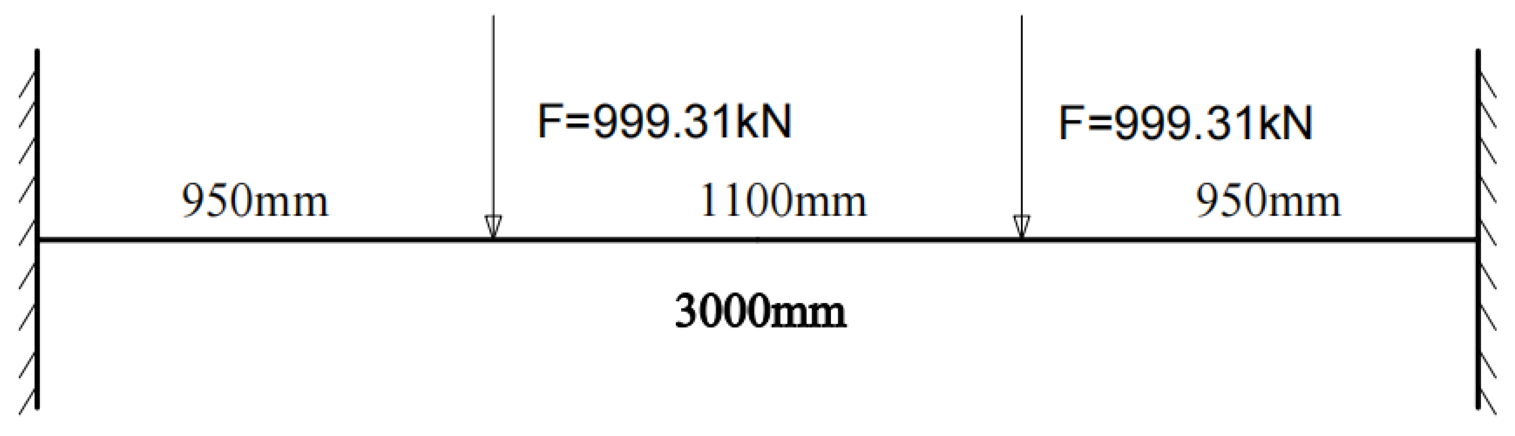
Figure 10.
Model of the joint force structure of the corbel beam and gate pier.
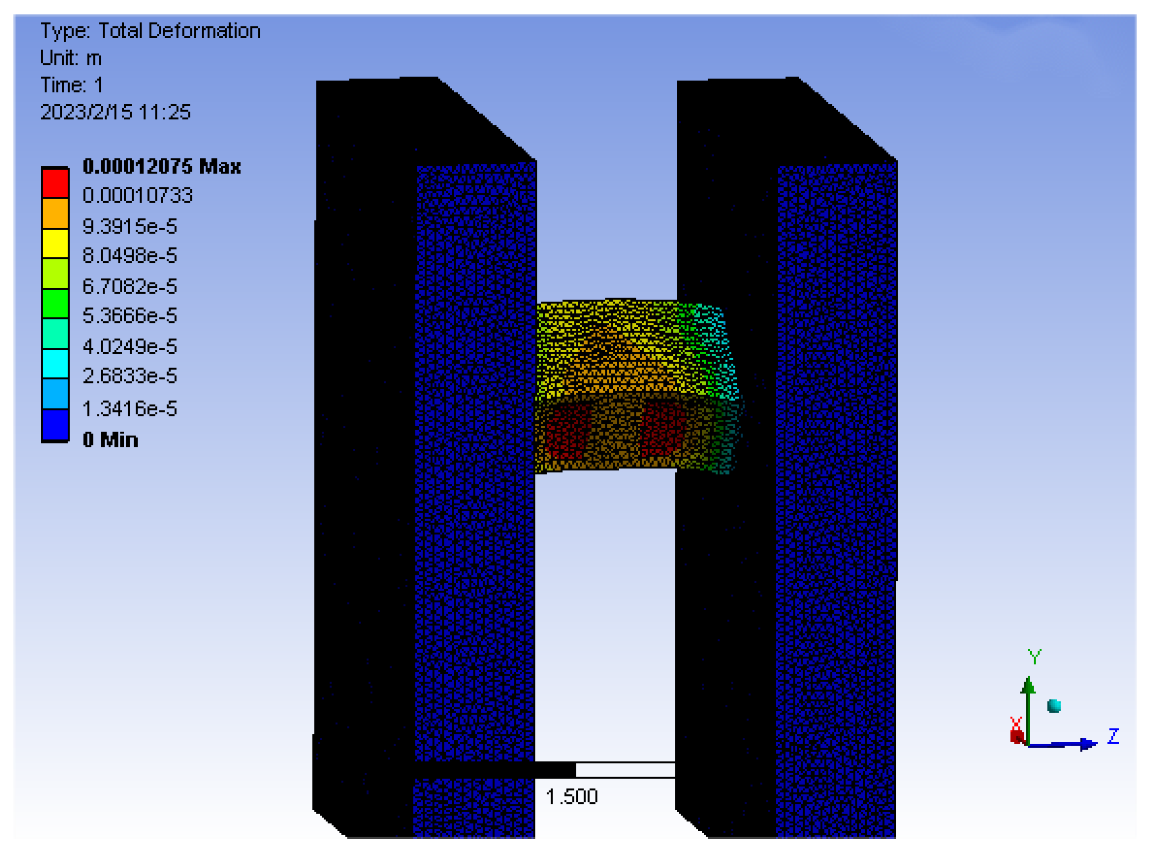
Figure 11.
Detail of the maximum tensile stress of the corbel beam and gate pier of the joint force structure model.
Figure 11.
Detail of the maximum tensile stress of the corbel beam and gate pier of the joint force structure model.
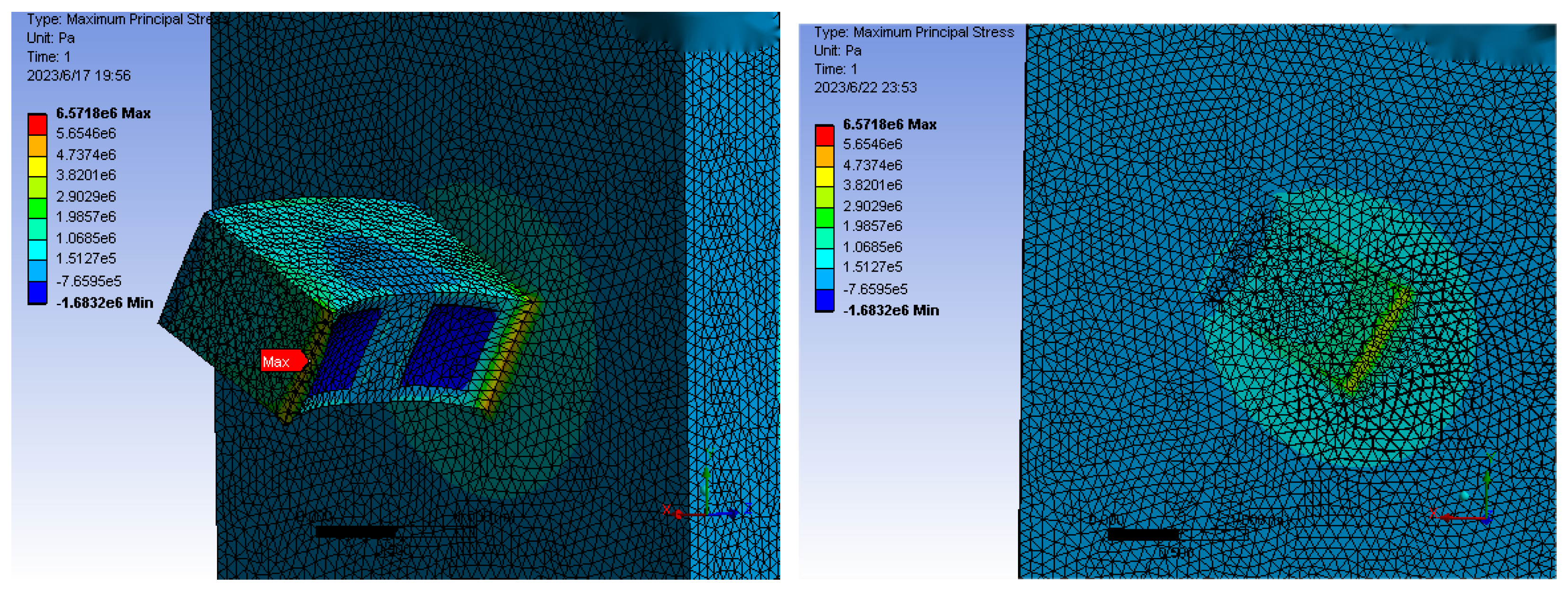
Figure 12.
Comparison of the results of different calculation methods.


Table 1.
Table of foundation information of corbel beam.
| Gate Hole Height HG | 1.70 m | Gate Pier Concrete Design Grade | C20 |
|---|---|---|---|
| Support beam section b | 0.8 m | Design grade of corbel concrete | C20 |
| Gate width | 2.00 m | Support beam section h | 1.2 m |
| Upstream head Hs | 49.70 m | The thickness of gate pier B | 1.00 m |
| Design tensile strength of reinforcing steel | Hydrostatic pressure Px (kN) | Hydrostatic pressure Py (kN) | Self-weight of corbel beam (kN) |
| 210 N/mm2 | 1783.6 | 945.9 | 44.1 |
Table 2.
Compressive strength test results of core specimens.
| Core Samples Number | Coring Position | Test Piece Number | Core Sample Diameter (mm) | Compressive Strength (MPa) |
|---|---|---|---|---|
| 1 | The left side of the first layer of the trestle bridge near the shoulder of the dam | LQ-1-1 | 149.4 | 38.6 |
| LQ-1-2 | 148.8 | 40.0 | ||
| LQ-1-3 | 150.8 | 45.9 | ||
| 2 | The middle of the first layer of the trestle | LQ-2-2 | 149.3 | 30.9 |
| 3 | The right side of the first layer of the trestle bridge near the shoulder of the dam | LQ-3-1 | 149.5 | 39.9 |
| LQ-3-2 | 149.9 | 32.8 | ||
| LQ-3-3 | 149.7 | 26.2 | ||
| 4 | The right side of the second layer of the trestle bridge near the shoulder of the dam | LQ-4-1 | 148.7 | 40.6 |
| LQ-4-2 | 150.1 | 42.6 | ||
| LQ-4-3 | 150.2 | 40.6 | ||
| 5 | The middle of the second layer of the trestle | LQ-5-1 | 150.4 | 40.9 |
| LQ-5-2 | 150.4 | 40.5 | ||
| LQ-5-3 | 150.8 | 43.5 | ||
| 6 | The left side of the second layer of the trestle bridge near the shoulder of the dam | LQ-6 | 150.4 | 45.9 |
| 7 | The right side of the third layer of the trestle bridge near the shoulder of the dam | LQ-7-1 | 150.5 | 42.5 |
| LQ-7-2 | 150.3 | 45.4 | ||
| LQ-7-3 | 150.4 | 41.9 | ||
| LQ-7-4 | 150.3 | 49.4 | ||
| 8 | The middle of the third layer of the trestle | LQ-8-1 | 150.3 | 48.4 |
| LQ-8-2 | 150.2 | 55.4 | ||
| 11 | The top of the dam near the right shoulder | LQ-11-1 | 150.1 | 43.9 |
Table 3.
Static compressive elastic modulus test results of dam concrete.
| Core Samples Number | Coring Position | Specimen Number | Modulus of Elasticity | Average Static Modulus |
|---|---|---|---|---|
| (GPa) | (GPa) | |||
| 2 | The middle of the first layer of the trestle | LQ-2-1 | 42.7 | 47.1 |
| 6 | The left side of the second layer of the trestle bridge near the shoulder of the dam | LQ-6 | 39.4 | |
| 9 | The third layer of the trestle bridge near the left shoulder of the dam | LQ-9 | 54.1 | |
| 10 | Upstream face near the left shoulder of the dam | LQ-10 | 43.5 | |
| 11 | The top of the dam near the right shoulder | LQ-11-2 | 49.0 | |
| LQ-11-3 | 54.0 |
Table 4.
Crack control test results in the local tension area of the gate pier (method (1)).
| b (mm) | B (mm) | The Standard Value of Concrete Tensile Strength ftk (N/mm2) | Eccentric Distance of Thrust to Gate Pier Thickness Centerline e0 (mm) |
|---|---|---|---|
| 800 | 1000 | 2.01 | 950 |
| Model 2 Equivalent standard value Fk (kN) | Security judgment result | ||
| 769.04 | 679.53 | Normal | |
Table 5.
The shear force of the cross-section where the center point of the corbel beam structure is stressed.
Table 5.
The shear force of the cross-section where the center point of the corbel beam structure is stressed.
| Fx (kN) | Fy (kN) | F (Shear Force) (kN) |
|---|---|---|
| 451.44 | 271.73 | 526.91 |
Table 6.
Crack control test results in the local tension area of the gate pier (method (2)).
| b (mm) | B (mm) | The Standard Value of Concrete Tensile Strength ftk (N/mm2) | The Eccentricity of Thrust to Gate Pier Thickness Centerline e0 (mm) |
|---|---|---|---|
| 800 | 1000 | 2.01 | 950 |
| Model 4 standard value Fk (kN) | Security judgment result | ||
| 769.04 | 526.91 | Normal | |
Disclaimer/Publisher’s Note: The statements, opinions and data contained in all publications are solely those of the individual author(s) and contributor(s) and not of MDPI and/or the editor(s). MDPI and/or the editor(s) disclaim responsibility for any injury to people or property resulting from any ideas, methods, instructions or products referred to in the content. |
© 2023 by the authors. Licensee MDPI, Basel, Switzerland. This article is an open access article distributed under the terms and conditions of the Creative Commons Attribution (CC BY) license (https://creativecommons.org/licenses/by/4.0/).
Share and Cite
MDPI and ACS Style
Lin, J.; Wang, R.; Zhao, Y.; Sun, Y. Research on the Safety Assessment of Corbel Beams of Reservoir Radial Gates Based on Real States. Appl. Sci. 2023, 13, 7578. https://doi.org/10.3390/app13137578
AMA Style
Lin J, Wang R, Zhao Y, Sun Y. Research on the Safety Assessment of Corbel Beams of Reservoir Radial Gates Based on Real States. Applied Sciences. 2023; 13(13):7578. https://doi.org/10.3390/app13137578
Chicago/Turabian StyleLin, Jiayi, Ronglu Wang, Yan Zhao, and Yuelin Sun. 2023. "Research on the Safety Assessment of Corbel Beams of Reservoir Radial Gates Based on Real States" Applied Sciences 13, no. 13: 7578. https://doi.org/10.3390/app13137578
Note that from the first issue of 2016, this journal uses article numbers instead of page numbers. See further details here.