Article

An Experimental Investigation on Mechanical Properties and Failure Characteristics of Layered Rock Mass

1
Key Laboratory of Road and Railway Engineering Safety Guarantee, Ministry of Education, Shijiazhuang Tiedao University, Shijiazhuang 050043, China
2
Hebei Metal Mine Safe and Efficient Mining Technology Innovation Center, Shijiazhuang 050043, China
3
School of Civil Engineering, Shijiazhuang Tiedao University, Shijiazhuang 050043, China
*
Author to whom correspondence should be addressed.
Appl. Sci. 2023, 13(13), 7537; https://doi.org/10.3390/app13137537
Submission received: 25 May 2023 / Revised: 21 June 2023 / Accepted: 25 June 2023 / Published: 26 June 2023

Abstract

:
Layered rock mass is a common rock mass structure with diverse forms and complex mechanical properties. Three types of composite layered rock mass prepared using sandstone and shale can be divided into sandwiched type, interbedded type and superimposed type. The total height of the combined rock mass is 50 mm, which is a cylinder composed of sandstone and shale with a diameter of 25 mm and different thickness. Uniaxial compression tests on sandstone, shale and combined rock mass were performed. The results show that, with the increase in the content of soft components, the compressive strength and elastic modulus of the combined rock mass tend to decrease. The mechanical properties of the superimposed rock mass will be between the two components and close to the soft component in numerical value. The mechanical properties of sandwiched rock mass are obviously affected by the properties of the sandwiched rock. When the content of the components is consistent, interbedded rock mass often shows higher strength and elastic modulus. Compared with other rock mass, interbedded rock mass has more stable mechanical properties. The stress–strain curve can be divided into the compaction stage, elastic stage, plastic development stage and post-fracture stage. The composition content of the rock mass plays a decisive role in the compaction stage. The failure modes are mainly shear failure and tensile failure. With the increase in soft rock content, the failure degree of soft rock is gradually weakened, and the failure modes show a trend from tensile failure to shear failure. The experimental results provide theorical guidance for underground engineering construction.

1. Introduction

In recent years, with the depletion of fossil energy worldwide and the rapid development of guidance technology, more and more underground mining projects have shifted from shallow excavation to deeper excavation. The research on the mechanical properties of layered rock has been gradually paid attention to and intensified [1]. As early as 1967, Wager [2] put forward the concept of layered rock mass in the study of igneous rock, which had an important influence on geological research. Subsequently, many scholars [3,4,5,6,7,8] have conducted a lot of studies on the properties of single-layered rock mass such as shale and sandstone. However, in deep engineering, more and more problems of layered rock masses, which are different from general rock mechanics, have been found. Additionally, these rock masses often have various shapes and complex mechanical properties. It brings challenges to underground engineering construction such as hydraulic fracturing, oil and gas exploitation, underground excavation, and so on [9,10,11,12]. Therefore, it is of great significance to explore the mechanical properties of layered rock for underground engineering construction.
In 1981, Duffault [13] introduced the term of sandwiched rock mass when classifying rock mass. According to the research progress, the layered rock mass can be divided into soft sandwiched rock mass, hard sandwiched rock mass, interbedded rock mass and so on. The current studies into layered rock mainly focuses on mechanical properties and deformation mechanism. In terms of mechanical properties, Chen et al. [14] used coal and oil shale with high strength and low elastic modulus to prepare the sandwich type and superposition type combination rock samples. Through uniaxial compression test, they found that the difference in the mechanical properties of coal and oil shale affected the stress state near the interface, resulting in the increase in coal strength and the decrease in oil shale strength. Sun et al. [15] found that, based on mineral composition, the uniaxial compressive strength and triaxial compression tests of shale reservoir, it was found that the mechanical properties of the shale reservoir in parallel bedding direction are less affected by lithology under uniaxial conditions. There is an increase in the compressive strength of rock, with a higher confinement in triaxial tests. The change in stress state is an important factor leading to the change in rock strength in the sample. Later, many scholars proved that the mechanical properties of combined rock mass are closely related to the content and strength of components. Wang et al. [16] studied the uniaxial compressive strength of the sandwich rock mass with different strength ratios of original materials. The relationship between the strength difference of lithological units, the percentage of soft rock and uniaxial compressive strength in soft rock and hard rock with alternating layered rock mass is revealed. Huang et al. [17] studied the influence of water pressure on the mechanical properties and permeability of layered rock mass through triaxial compression tests under different water pressures and low confining pressures. The results show that the increase in water pressure reduces the peak strength of layered rock mass, but accelerates the expansion of cracks and significantly enhances the peak permeability of layered rock mass. Li et al. [18] conducted uniaxial compression tests on combination rock samples to reveal their mechanical properties. The conclusion is that combination rocks with thick interlayers are more likely to fail than combination rocks with thin interlayers. Li et al. [19] prepared superimposed and sandwiched rock masses using coal and rock coal bi-material samples. Uniaxial compression tests showed that the strength of coal determines the overall strength of the bi-material sample. Lisanne et al. [20] studied the influence of the difference in rock strength between adjacent rock strata on cracks. The results show that the increase in strength difference can prevent the crack from expanding into a stronger layer. Li et al. [21] analyzed the stress–strain curve characteristics, strength characteristics and failure characteristics of interbedded sandstones with different sandwiched thicknesses under uniaxial and conventional triaxial compression conditions. The research results show that, with the increase in sandwiched thickness, the uniaxial compressive strength of sandwiched sandstones first decreases first and then increases. In terms of deformation, Zhang et al. [22] proposed the constitutive relation and elastic parameter calculation model of parallel, vertical, and inclined layered rock mass by combining Hooke spring model and coordinate transformation method. Through the analysis of sensitivity, it is concluded that the elastic parameters of layered rock mass are controlled by the thickness, elastic parameters and dip angle of layer and sandwich rock. Then, Wei et al. [23] derived the calculation formula of deformation parameters of layered rock mass based on elastic theory.
At present, although relevant scholars have performed a lot of research into the mechanical properties of sandwiched rock mass, including interbedded rock mass superimposed rock mass after compression, there is a lack of comparative analysis for these complex strata. Thus, by using sandstone and shale to make sandwiched rock mass, interbedded rock mass and superimposed rock mass, uniaxial compression tests are carried out on combination samples with different thicknesses as well as different layers and different combination methods. The mechanical properties such as compressive strength, elastic modulus and failure mode are analyzed from the aspects of combination mode, rock content and the layer number of each specimen, and the variation law of mechanical properties after uniaxial compression is discussed.

2. Uniaxial Compression Test of Layered Rock Mass

2.1. Test Scheme

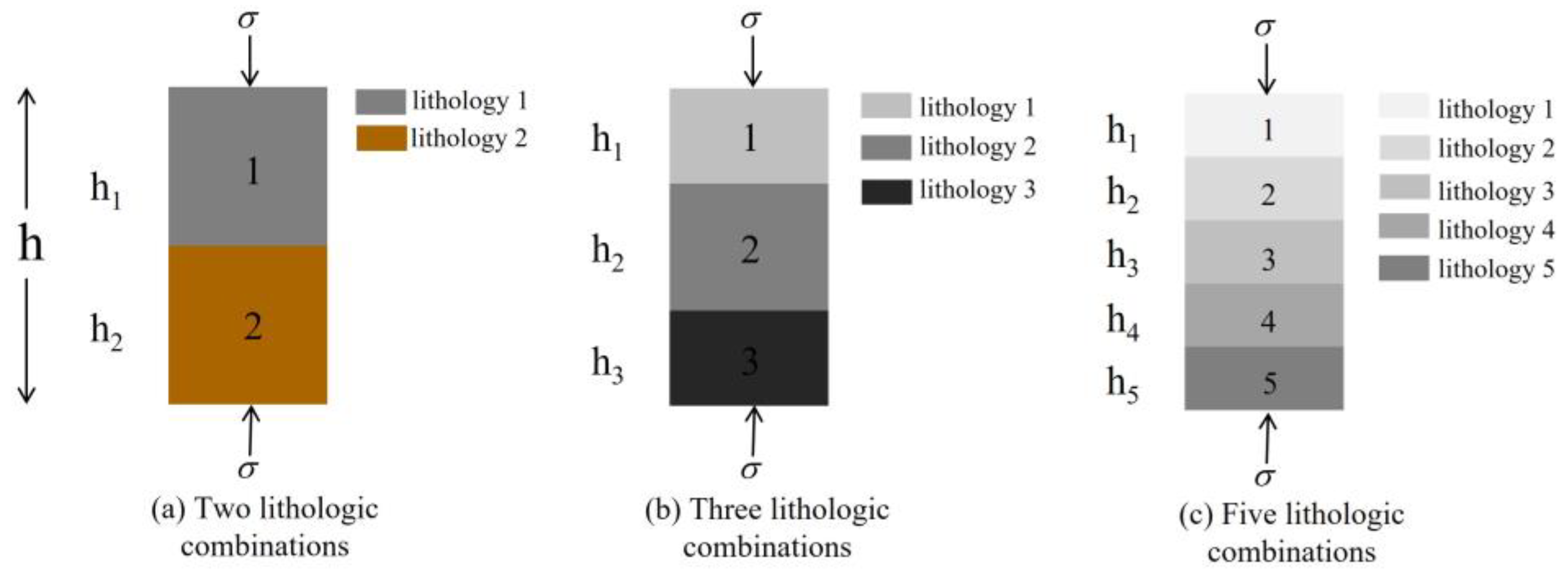
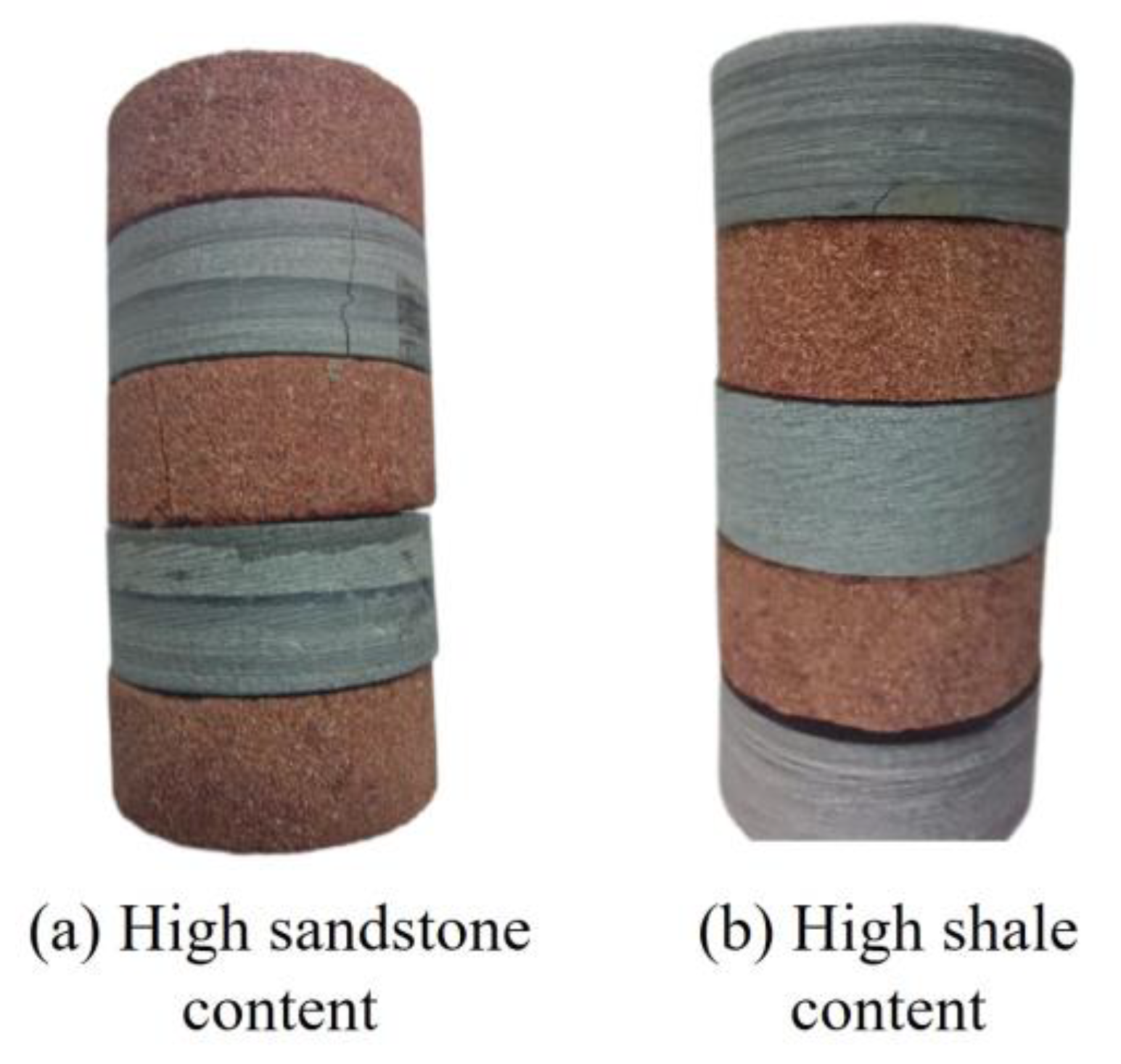
Berisavljević et al. [24] carried out a series of uniaxial compression tests on the combination specimens of sandstone and siltstone. The experimental results show that the inhomogeneity of sample strength seriously affects the accuracy of the experiment. This is because the rocks collected in the field have certain limitations and it is difficult to ensure the uniformity and integrity of the rocks. Therefore, the most common method of preparing samples is to collect rocks with different lithological properties, cut, polish and shape them to the desired size separately, and finally assemble them. The same cementation is used between layers and the same thickness is applied. In this experiment, the sandstone and shale were made into cylindrical samples with diameters of 25 mm and different thicknesses, and the height of the combined samples was 50 mm. In order to analyze the influence of different combination characteristics, the samples are divided into four types. As shown in Table 1, these are single rock, superimposed rock mass, sandwiched rock mass and interbedded rock mass. The schematic diagram of the sample design scheme is shown in Figure 1. This study discusses that soft rock and hard rock are not the mechanical classification of engineering rock mass, but are divided into soft rock and hard rock according to their relative strength. When the uniaxial compressive strength of hard rock is more than one times that of soft rock, they can be divided into soft rock and hard rock.

2.2. Test Results

The uniaxial compression test of the prepared combination rock mass was carried out by TAW-2000 rock triaxial shear tester, and a continuous loading method was used to load the sample to failure. The compressive strength, elastic modulus and stress–strain curves of the samples were obtained. The average value of each group of experimental data was used as the test result. The test data are shown in Table 2.

3. Mechanical Properties of Layered Rock Mass

3.1. Comparative Analysis of Compressive Strength

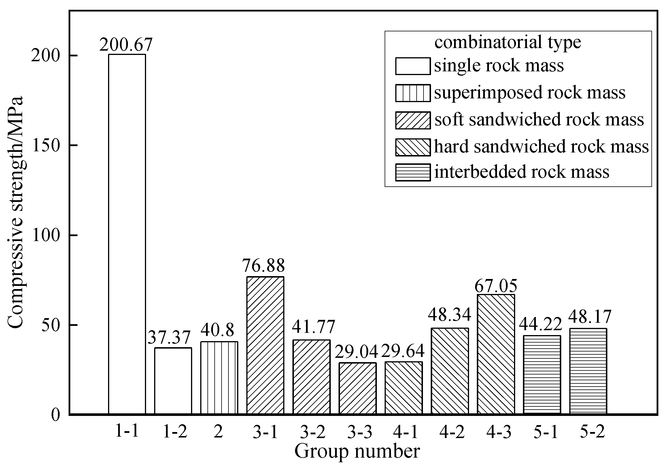
The compressive strength characterizes the ability of rock to resist damage, so the combined characteristics of the compressive strength of the rock mass are analyzed. It is of great significance for understanding the fracture behavior of deep layered rock mass. Figure 2 summarizes the compressive strength values of all rock masses. According to the compressive strength of the single rock mass, the average uniaxial compressive strength of sandstone is 37.37 MPa, and that of shale is 200.67 MPa. This is because the shale used in this experiment has good compactness, while the mineral component particles of sandstone are larger and weakly cemented, so there is a large difference in strength. The compressive strength of shale is five times that of sandstone. The uniaxial compressive strength of the combination is between 29 and 80 MPa, which is between the strength of sandstone and shale. In combination rock samples, both sandstone and shale bear the stress of loading at both ends. As the existence of high-strength shale improves the overall bearing capacity, the compressive strength of the combination rock samples is higher than that of single sandstone rock samples. However, due to the low compressive strength of sandstone, the stress in the loading process first reaches the maximum bearing capacity of sandstone. Although it does not reach the bearing capacity of shale, the combined sample has lost its bearing capacity. Thus, the strength of the combined sample is lower than that of a single shale sample. In addition, the compressive strength of the combined samples is more similar to that of sandstone. This indicates that low strength rock mass plays a key role in the overall strength of rock mass in different lithologic assemblage strata.
In summary, the compressive strength of the combined sample is between the compressive strength of the combined component, which is biased towards the compressive strength of the soft rock. The soft rock of the combination plays a decisive role in the strength of the combination.
Figure 3 analyzes the strength characteristics of the superimposed rock mass. The strength of 1-1 shale is 200.67 MPa, The strength of 1-2 sandstone is 37.37 MPa. Additionally, the compressive strength of superimposed rock mass 2 is 40.8 MPa, which is 1.09 times that of sandstone, but only 0.203 times that of shale. This shows that the strength of soft and hard superimposed rock mass is slightly higher than that of sandstone. Compared with the strength of shale, the strength will decrease greatly. Therefore, for the soft and hard superimposed rock mass, the strength is greatly affected by sandstone (relatively soft rock mass). When the content of each component is the same, its strength will be close to the strength of soft rock mass. Relevant scholars’ research [12] also shows that the strength of composite rock will be between the compressive strength of two kinds of rock [14].
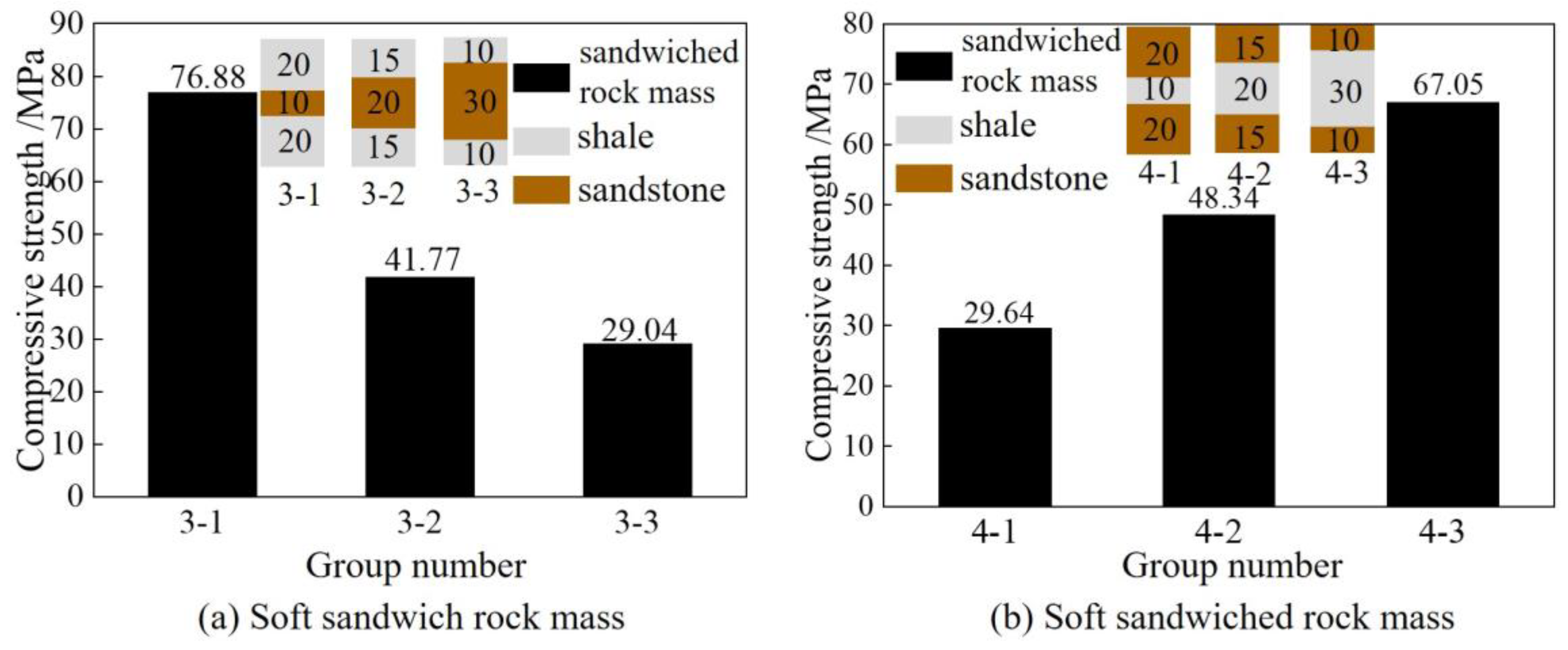
Figure 4a shows the soft sandwiched rock mass with different component content. The sandwich height of the samples from groups 3-1, 3-2 and 3-3 increased successively, and the compressive strength of samples with sandstone content of 20%, 40% and 60% were 76.88 MPa, 41.77 MPa and 29.04 MPa, respectively. It can be observed that the strength of combination was continuously weakened with the increase in the content of sandwiched sandstone. Figure 4b shows hard interbedded rock mass with a different component content. The interlayer height of samples in groups 4-1, 4-2 and 4-3 successively increased, the shale content was 20%, 40% and 60%, respectively, and the compressive strength was 29.64 MPa, 48.34 MPa and 67.05 MPa, respectively. It can be observed that the strength of combination body increases with the increase in shale content. This also indicates that, for the interbedded rock mass, the strength of the rock mass mainly depends on the lithology and content of the rock strata. When the sandwich is sandstone (soft rock mass), the strength of the assemblage increases with the decrease in the sandwiched rock mass content. When the sandwich is shale (hard rock), the strength of the combination decreases with the decrease in sandwich content.
In summary, the effect of the sandwich on the overall strength of the rock mass is as follows, when the strength of the sandwich is lower than that of surrounding rock, the overall strength of the rock layer decreases with the increase in the thickness of sandwich. When the strength of the sandwich is higher than that of surrounding rock, the overall strength of the rock stratum increases with the increase in sandwiched thickness.
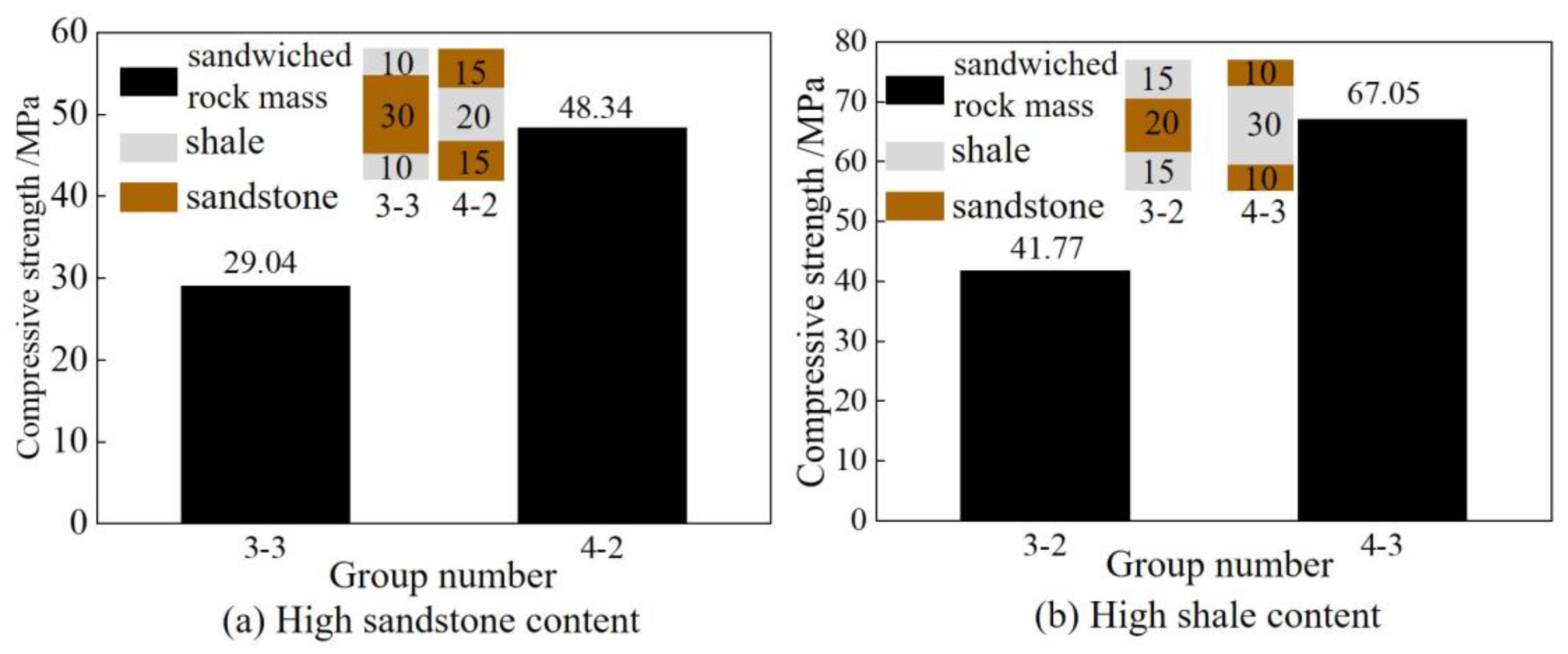
Figure 5 analyzes the effect of rock position on strength. The shale content of samples 3-2 and 4-3 is 60%, and the compressive strength is 41.77 MPa and 67.05 MPa, respectively. When the soft rock layer is in the sandwich, the strength of the sample will be low. In Figure 5b, the shale content of samples 3-3 and 4-2 is 40%, and the compressive strength is 29.04 MPa and 48.31 MPa, respectively. When the hard rock layer is in the sandwich, the strength of the sample will be higher.
In conclusion, when the content of each component of the sample is unchanged, the influence of the sandwich on the strength is the strongest. When the sandwich is a weak rock layer, the sample shows smaller strength. When the sandwich is a hard rock layer, the sample shows greater strength.
Figure 6 compares and analyzes the influence law of the number of rock layers on the strength of the superimposed rock mass and interbedded rock mass. The strength of the superimposed rock mass is 40.8 MPa, and that of the interbedded rock mass is 44.22 MPa and 48.17 MPa. From the perspective of the component content, taking shale as an example, the shale content of superimposed rock mass is 50%, and that of interbedded rock mass is 60% and 40%, respectively, between the superimposed rock mass. From the perspective of the component content alone, the strength of the superimposed rock mass is between the two groups of interbedded rock mass, but the strength of interbedded rock mass is higher than that of superimposed rock mass. This indicates that the number of layers has an important effect on the strength. When the composition content of the combination is similar, the overall strength will increase with the increase in the number of layers.
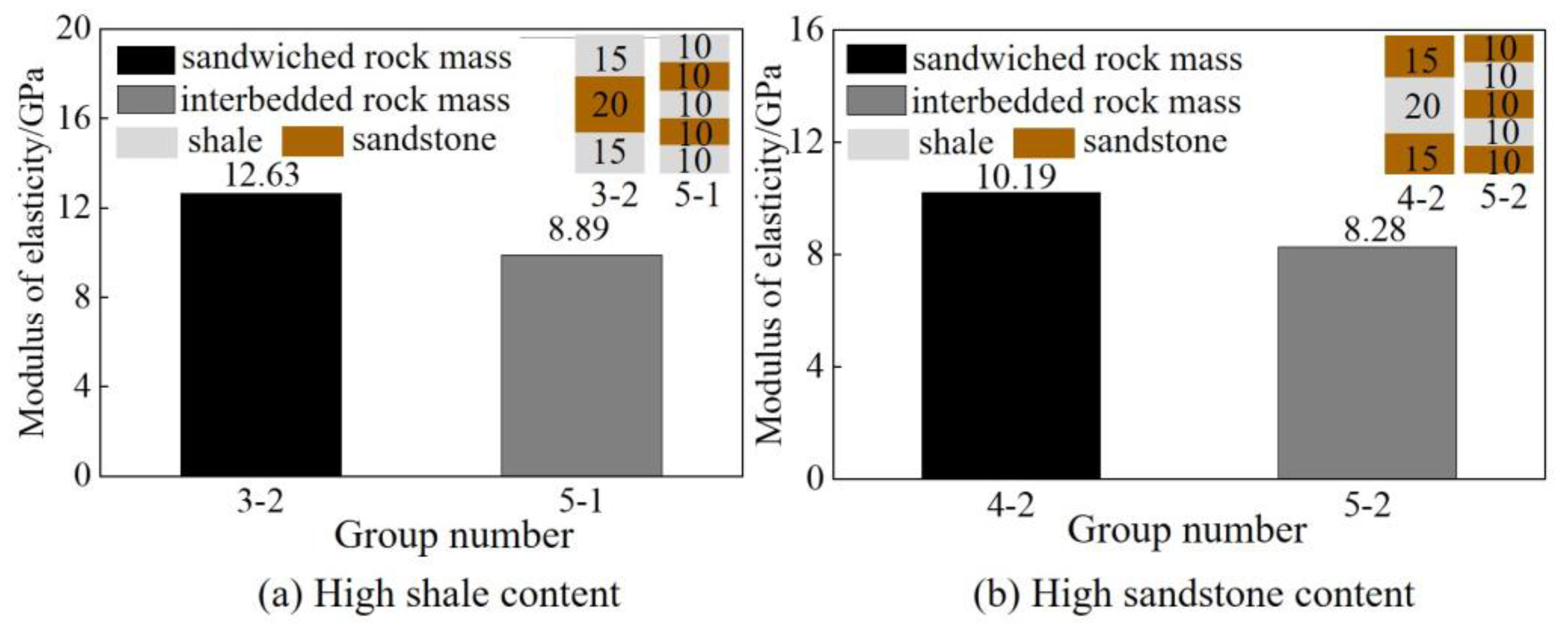
Figure 7 analyzes the strength characteristics of sandwiched rock mass and interbedded rock mass with the same component content. The strength of samples 3-2 and 5-1 are 41.77 MPa and 44.22 MPa, respectively. The strength of samples 4-2 and 5-2 are 48.34 MPa and 48.17 MPa, respectively. The intensity is very similar. This indicates that the level of component content has an important effect on the rock mass of interbedded and sandwiched rock mass. The strength is similar when the component content is the same and the surrounding rock type is the same.
In conclusion, the composition content has an important effect on the rock mass. The greater the proportion of hard rock, the easier it is for the combination to show greater strength. In addition, the strength of the superimposed rock mass is greatly affected by the type of components. The strength value of the superimposed rock mass is between the strength of each component, which is slightly higher than that of the weak component, but significantly lower than that of the hard component. The strength of the sandwiched rock mass is closely related to the thickness of the sandwich and the strength of the sandwich and surrounding rock. Interbedded rock mass has the largest number of layers, the strength of interbedded rock mass is similar to that of sandwiched rock mass when the composition content is the same or similar and the type of surrounding rock is the same. When the composition content is similar, the strength of interbedded rock mass is slightly higher than that of superimposed rock mass. It is similar to the current research results [14]. The strength of composite rock mass will be between the strength of two kinds of rock and close to low strength [19].

3.2. Comparative Analysis of Elastic Modulus

Elastic modulus is the ratio of stress to strain change value of the object in the elastic deformation stage, that is, the stress required for the unit elastic deformation of the material under the action of external force. The elastic modulus characterizes the ability of the object to resist elastic deformation. Therefore, it is of great significance to clarify the influence of combination characteristics on the elastic modulus for understanding the deformation law of rock in deep combined strata.
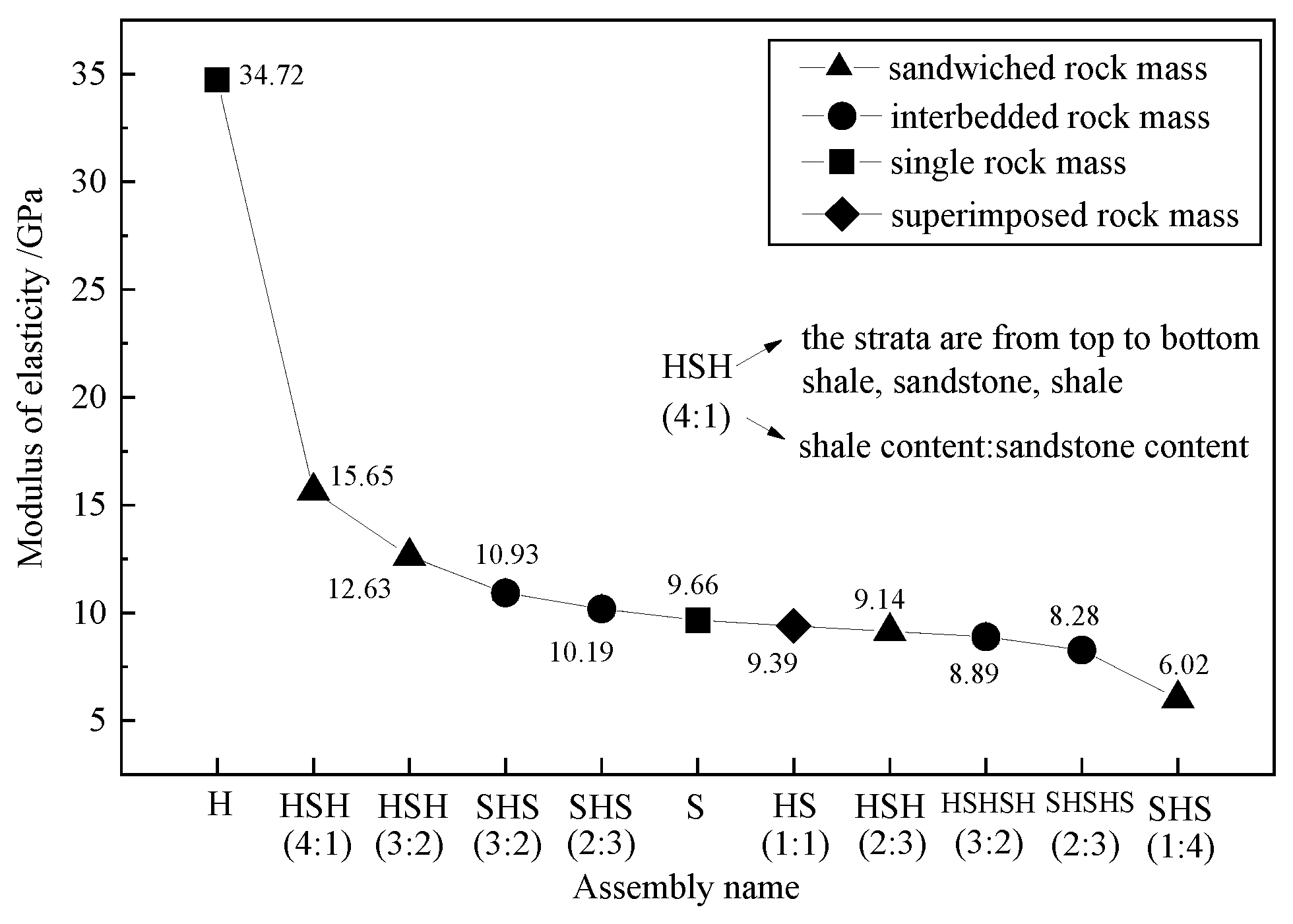
To compare the elastic modulus, Figure 8 is drawn according to the order of the elastic modulus and the component content and layered characteristics of the sample. The values of the elastic modulus was closely related to the component content. The higher the shale content is, the lower the sandstone content is, and the higher the elastic modulus of the rock mass is. In addition, the number of layers and the location of the rock layer also affect the elastic modulus. When the component content is the same, the elastic modulus of the hard sandwich is smaller than that of the soft sandwich. The elastic modulus of the interbedded rock mass with the same component content is smaller than that of the sandwich rock mass.
Figure 9 shows the stress diagram of superimposed, sandwiched and interbedded rock masses. Assuming that the stress between layers is equal, according to Hooke’s law, the shape variable of the assemblage can be expressed by Equation (1), and that of each rock layer can be expressed by Equation (2).
Δ h = F h E A
Δ h i = F h i E i A
where h represents the height of rock strata, F represents the pressure of the rock mass, E represents the elastic modulus and A represents the upper and lower area of the rock mass.
The total deformation is the sum of the deformation of the rock layer, as shown in Equation (3). Thus, the elastic modulus of the combination can be expressed by Equation (4).
Δ h = h i
1 E = 1 h h 1 E 1 + h 2 E 2
For Figure 9b,c, the elastic modulus of the combination can be expressed by Equations (5) and (6) as
1 E = 1 h h 1 E 1 + h 2 E 2 + h 3 E 3
1 E = 1 h h 1 E 1 + h 2 E 2 + h 3 E 3 + h 4 E 4 + h 5 E 5
The elastic model of the combination is only related to the elastic modulus of each component and the height of the rock layer. For the combination containing only two materials, the elastic modulus can be expressed by Equation (7).
1 E = α E 1 + β E 2
The percentage of the height of the material with a surface elastic modulus of E1 to the total height of the combination. The percentage of the height of the material whose modulus of elasticity is E2 in the total height of the combination. Substitute β = 1 − α into Equation (8) to obtain:
E = E 1 E 2 α ( E 2 E 1 ) + E 1
If E2 > E1, the larger α (the higher the total height of the material whose elastic modulus is E1), the lower the elastic modulus of the combination. If E2 < E1, the larger α (the higher the total height of the material whose elastic modulus is E1), the higher the elastic modulus of the combination will be. Therefore, for the elastic modulus of a combination containing only two materials, when the component with a large elastic modulus accounts for a large number, the elastic modulus of the combination will be larger. On the contrary, when the component with a small elastic modulus accounts for a large number, the elastic modulus of the combination will be smaller.
Figure 10 shows the comparison of the elastic modulus between the sandwiched rock mass and interbedded rock mass with the same component content. When the component content is the same, the elastic modulus of the rock mass should be the same or remain similar. However, it can be seen from Figure 10 that the elastic modulus of the interbedded rock mass in the two groups of samples is significantly lower than that of the sandwiched rock mass. The reason is that there are structural planes between the upper and lower layers on the stratified interface. In contrast to the intact rock mass without stratification, the contact mode between two walls under the structural plane is several points or a local structural plane. Although the layered interface was treated before the experiment, the structural plane effect was broken to a certain extent, and the upper and lower structural planes were still in incomplete contact, which would lead to the decline of the mechanical properties of similar materials. The more layers there are, the more severely the mechanical properties of similar materials will decline. The discontinuity between layers will increase, which will increase the deformation of rock mass, so the elastic modulus will decrease.
In conclusion, the elastic modulus of the combination is mainly affected by the content of components and the number of layers. The greater the content of hard components, the lesser the deformation and the greater the elastic modulus of rock mass. When the component content is the same, the increase in the number of layers will form more structural planes and generate larger shape variables, and the elastic modulus will decrease. Previous study has suggested that the elastic modulus of the combination will be close to that of the rock with a high content [16]. This study draws more detailed conclusions through formula derivation and experimental data.

4. Failure Characteristics of Layered Rock Mass

4.1. Analysis of Stress–Strain Curve

The uniaxial compression stress–strain curve of the combination can be roughly divided into four stages, similarly to a previous study [21]. As shown in Figure 11 OA stage, the compaction stage, there are micro-cracks in the rock mass itself. With the increase in stress, these micro-cracks gradually close, and the rock will be compacted to form early nonlinear deformation, and the stress–strain curve is concave. The AB stage, elastic deformation stage the stress–strain curve of this stage shows an approximately linear shape, which can be approximated as elastic deformation. In the BC stage, the plastic deformation stage from the elastic stage after the test block began to enter the plastic stage, the development of micro-fracture undergoes a qualitative change, the fracture continues to develop, the micro-cracks in the specimen under the action of pressure gradually formed a semi-through joint in the test block, the specimen has a volume compression into a volume expansion and the axial strain increases sharply. After the C point, the post-fracture stage, after the bearing capacity of the test block reaches the peak strength, its internal structure is seriously damaged. The crack penetrates the entire test block to form a macroscopic fracture surface. The bearing capacity decreases sharply with the deformation of the test block; however, it does not drop to zero, indicating that the test block after failure still has a certain bearing capacity.
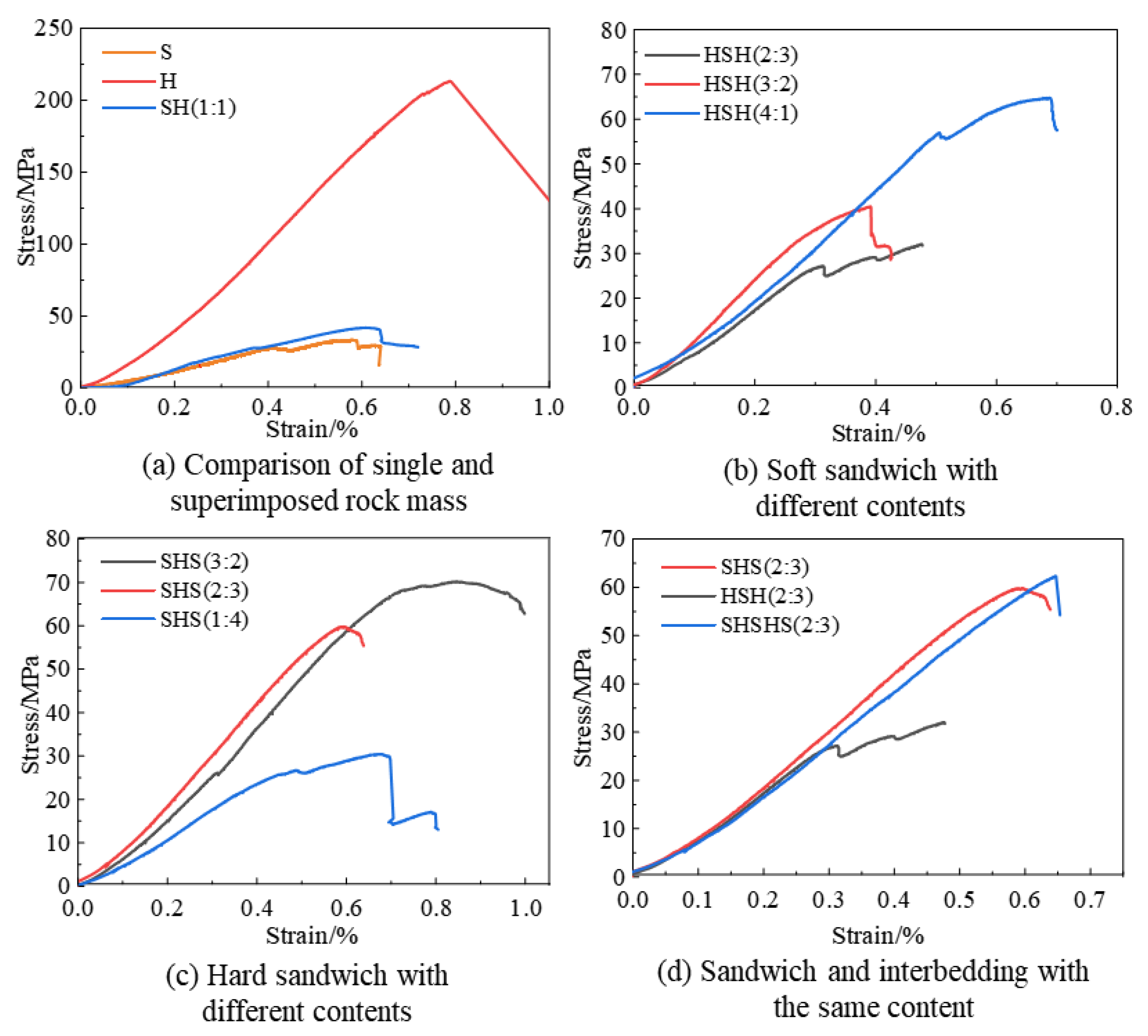
According to the composition content of the rock sample, the number of strata and the combination way, the stress–strain curve of the assemblage will also show different characteristics. The stress–strain curve was plotted in Figure 12 for comparative analysis. The maximum strain value of sandstone is 0.62, and that of shale is 0.83, which is related to the material of the sample itself and its own micro-cracks. Similarly to the conclusion drawn above, the maximum strain value of the combination body is basically between the two. Figure 12a shows the comparison between the superimposed rock mass and sandstone or shale. It can be seen that the stress–strain curve of the superimposed rock mass has the same trend as that of sandstone, indicating that the mechanical properties of the assemblage are mainly affected by sandstone and shale. Figure 12b shows the soft sandwiched rock mass with different component contents. As can be seen from the curve, the peak strain of the HSH (4:1) sample with the lowest sandstone content is above 0.7, while the other two groups of samples have a relatively high interlayer content and the maximum strain value is approximately 0.4. This indicates that, when the thickness of the soft sandwiched rock mass is small, the rock mass is more likely to have a greater strain value. Figure 12c shows the hard sandwiched rock mass with a different content. The SHS (1:4) sample shows an obvious stress drop phenomenon, while the other two groups of samples with a higher sandwiched content have smooth curves. This indicates that the mechanical properties of the combination are more unstable when the content difference of components is relatively large. The compaction stages of the curves in Figure 12d are almost identical. This indicates that the component content of the sandwiched rock mass and superimposed rock mass plays a decisive role in the mechanical properties of the samples at the initial loading stage.

4.2. Damage Pattern of Rock Sample

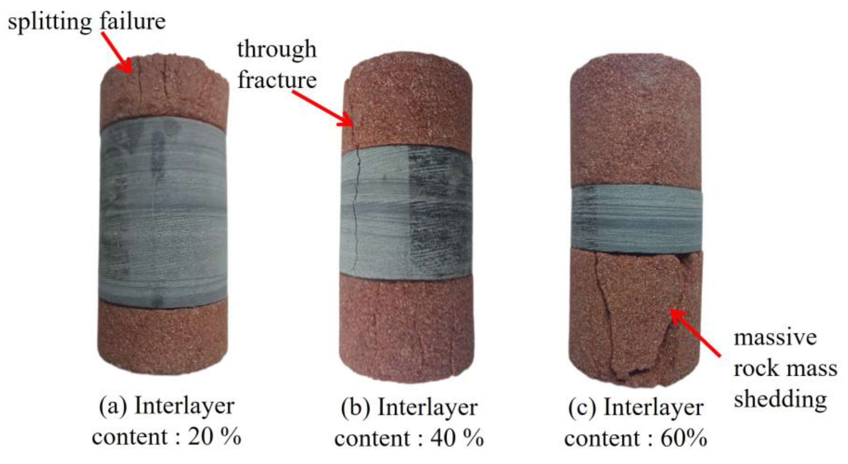
Figure 13 shows the fracture characteristics of the soft sandwiched rock mass with different component contents. When the content of the interlayer is 20%, as shown in Figure 13a, the sandstone layer in the sample falls off, and the shale part cracks along the direction of the sandstone falling off. Under the vertical load, the sandstone part first expands and a part of the rock mass falls off, forming a highly concentrated area of stress at the interface between the soft and hard layers. Finally, the axial fracture failure occurs in the shale part. When the interlayer content is 40%, as shown in Figure 13b, shear failure occurs in sandstone, and two approximately parallel oblique fractures appear, with volume dilatation, but not as obvious as the former. When the content of the interlayer is 60%, as shown in Figure 13c, shear failure occurs in the sandstone part. Due to the high proportion of sandstone, the failure characteristics are similar to that of sandstone.
Therefore, the failure mode of the rock mass containing a soft sandwich is related to the content of rock strata. With the increase in the content of sandstone, the failure degree of sandstone gradually weakens, and the failure mode presents the trend of splitting failure to shear failure.
Figure 14 shows the failure characteristics of the hard sandwiched rock mass with different component contents. When the sandwich content is 60%, as shown in Figure 14a, splitting failure occurs in the sandstone part, and longitudinal fractures of the sample are concentrated in the sandstone, without obvious phenomena on the shale surface. When the sandwich content is 40%, as shown in Figure 14b, the sandstone is also split failure, with three vertical fractures at the lower end and one vertical fracture at the upper end penetrating through the shale. When the sandwich content is 20%, as shown in Figure 14c, a large area of volume shedding occurs in the lower surrounding rock.
Therefore, the failure characteristics of hard sandwiched rock mass are related to the component content. When the content of the sandwiched rock is high or low enough, the failure of the rock mass mainly occurs in the surrounding rock. When the content of sandwiched rock is similar to that of surrounding rock, the failure of both the sandwiched rock mass and surrounding rock mass will occur.
Figure 15 shows the failure characteristics of the interbedded rock mass. As shown in Figure 15a, the top sandstone part has a vertical crack, but without crossing the shale section, there is no obvious phenomenon. The rest of Figure 15b shows a sample surface without apparent damage. It can be seen that the strength of the soft and hard interbedded rock mass is similar to that of other rock mass under the condition of constant lithology and proportion. However, the damage degree shown after compression will be significantly weakened. It is difficult to produce cracks.

5. Conclusions

Through uniaxial compression experiments on different types of rock masses, the compressive strength, elastic modulus and failure characteristics of the samples were obtained. The influence of component content, number of layers and rock position on the combined rock mass was analyzed. The conclusions are as follows:
(1) The mechanical properties of the superimposed rock mass, such as strength and elastic modulus, are between the sandstone and shale. The strength and elastic modulus of superimposed rock mass decrease greatly compared with the shale, but increase little compared with sandstone. Sandwiched rock mass can be divided into soft sandwiched rock mass and hard sandwiched rock mass. The overall strength of the soft sandwiched rock mass decreases with the increase in sandwich thickness, while the overall strength of hard sandwiched rock mass increases with the increase in rock thickness. Compared with the former, the mechanical properties of the interbedded rock mass tend to be more stable; the strength and elastic modulus of the interbedded rock mass only change a little after changing the composition content and formation location. Compared with the sandwiched rock mass, the strength of the interbedded rock mass is similar to that of the sandwiched rock mass, but the elastic modulus of the interbedded rock mass decreases with the increase in the number of layers.
(2) The stress–strain curve of the combination can be divided into the compaction stage, elastic stage, plastic stage and post-peak bearing stage. The component content of rock mass plays a decisive role in the compaction stage. When the component content is unchanged, the interbedded rock mass will produce a larger strain value.
(3) The failure modes of the combination are mainly shear failure and splitting failure. The failure mode of the rock mass with the soft sandwich is related to the content of the rock layer. With the increase in the sandwich content, the failure degree of sandstone is gradually weakened, and the failure mode shows the trend of splitting failure to shear failure. For hard sandwich rock mass, when the sandwich content is high or low enough, the failure of the rock mass mainly occurs in the surrounding rock. When the content of the sandwich is similar to that of the surrounding rock, both the sandwich and surrounding rock will appear. The properties of soft and hard interbedded rock mass are more stable and the damage degree is less.
(4) Layered rock mass is the most common type of rock mass in practical engineering. The research results of this paper can provide a reference for the complex layered rock mass problems encountered in oil and gas exploitation and underground excavation. The cementation between the layered rock samples prepared in this experiment is the same. In fact, the cementation between the rock layers also affects the strength of the rock mass. Therefore, the cementation between rock layers can be further studied as a variable.

Author Contributions

Conceptualization, Y.Z.; methodology, Y.Z. and H.W.; software, T.Z.; validation, Y.Z.; formal analysis, Q.N.; investigation, Y.Z.; resources, Y.Z.; data curation, T.Z. and H.Y.; writing—original draft preparation, T.Z.; writing—review and editing, Y.Z.; visualization, Y.Z.; supervision, Y.Z. and W.W.; project administration, Y.Z.; funding acquisition, Y.Z. All authors have read and agreed to the published version of the manuscript.

Funding

This study was funded by the Natural Science Foundation of Hebei Province (E2021210036 and E2021210128).

Institutional Review Board Statement

Not applicable.

Informed Consent Statement

Not applicable.

Data Availability Statement

Due to the need for follow-up research, participants of this study did not agree for their data to be shared publicly, so supporting data is not available.

Conflicts of Interest

All authors certify that they have no affiliations with or involvement in any organization or entity with any financial interest or non-financial interest in the subject matter or materials discussed in this manuscript.

References

  1. Wagner, H. Deep Mining: A Rock Engineering Challenge. Rock Mech. Rock Eng. 2019, 52, 1417–1446. [Google Scholar] [CrossRef] [Green Version]
  2. Buddington, A.F. Layered igneous rocks. Chem. Geol. 1970, 6, 241–243. [Google Scholar] [CrossRef]
  3. Suo, Y.; Chen, Z.; Rahman, S.S.; Chen, X. Experimental study on mechanical and anisotropic properties of shale and estimation of uniaxial compressive strength. Energy Sources Part A Recovery Util. Environ. Eff. 2020. [Google Scholar] [CrossRef]
  4. Hou, P.; Gao, F.; Yang, Y.; Zhang, X.; Zhang, Z. Effect of the layer orientation on mechanics and energy evolution characteristics of shales under uniaxial loading. Int. J. Min. Sci. Technol. 2016, 26, 857–862. [Google Scholar] [CrossRef]
  5. Li, H.; Yang, Z.; Li, H. Mechanical Characteristics and Failure Mechanism of Siltstone with Different Joint Thickness. Adv. Civ. Eng. 2020, 2020, 3824538. [Google Scholar] [CrossRef]
  6. Abdi, Y.; Khanlari, G.-R.; Jamshidi, A. Correlation between Mechanical Properties of Sandstones and P-Wave Velocity in Different Degrees of Saturation. Geotech. Geol. Eng. 2018. [Google Scholar] [CrossRef]
  7. Ma, J.; Jiang, N.; Wang, X.; Jia, X.; Yao, D. Numerical Study of the Strength and Characteristics of Sandstone Samples with Combined Double Hole and Double Fissure Defects. Sustainability 2021, 13, 7090. [Google Scholar] [CrossRef]
  8. Yan, C.; Deng, J.; Hu, L.; Chen, Z.; Yan, X.; Lin, H.; Tan, Q.; Yu, B. Brittle failure of shale under uniaxial compression. Arab. J. Geosci. 2015, 8, 2467–2475. [Google Scholar]
  9. Zhang, J. Borehole stability analysis accounting for anisotropies in drilling to weak bedding planes. Int. J. Rock Mech. Min. Sci. 2013, 60, 160–170. [Google Scholar] [CrossRef]
  10. Everitt, R.A.; Lajtai, E.Z. The influence of rock fabric on excavation damage in the Lac du Bonnett granite. Int. J. Rock Mech. Min. Sci. 2004, 41, 1277–1303. [Google Scholar] [CrossRef]
  11. Zheng, Y.; He, R.; Huang, L.; Bai, Y.; Wang, C.; Chen, W.; Wang, W. Exploring the effect of engineering parameters on the penetration of hydraulic fractures through bedding planes in different propagation regimes. Comput. Geotech. 2022, 146, 104736. [Google Scholar] [CrossRef]
  12. Huang, L.; Liu, J.; Zhang, F.; Dontsov, E.; Damjanac, B. Exploring the influence of rock inherent heterogeneity and grain size on hydraulic fracturing using discrete element modeling. Int. J. Solids Struct. 2019, 176–177, 207–220. [Google Scholar] [CrossRef]
  13. Duffaut, P. Structural Weaknesses in Rocks and Rock Masses Tentative Classification and Behaviour. In Proceedings of the Isrm International Symposium, ISRM-IS, Tokyo, Japan, 21–24 September 1981. [Google Scholar]
  14. Chen, S.; Yin, D.; Jiang, N.; Wang, F.; Zhao, Z. Mechanical properties of oil shale-coal composite samples. Int. J. Rock Mech. Min. Sci. 2019, 123, 104120. [Google Scholar] [CrossRef]
  15. Sun, W.-T.; Li, Z.-H.; Lou, Y.-S.; Zhu, L.; Wu, H.-M.; Lenwoue, A.R.K.; Liu, Q. Mechanical Properties of Shale-Reservoir Rocks Based on Stress–Strain Curves and Mineral Content. Geofluids 2022, 2022, 2562872. [Google Scholar] [CrossRef]
  16. Wang, Z.; Wang, M.; Zhou, L.; Zhu, Z.; Shu, Y.; Peng, T. Research on uniaxial compression strength and failure properties of stratified rock mass. Theor. Appl. Fract. Mech. 2022, 121, 103499. [Google Scholar] [CrossRef]
  17. Huang, W.; Wang, H.; Zhang, T.; He, M.; Yan, L. Hydraulic pressure effect on mechanical properties and permeabilities of layered rock mass: An experimental study. Eur. J. Environ. Civ. Eng. 2023, 27, 2422–2433. [Google Scholar] [CrossRef]
  18. Li, H.; Wang, J.; Li, H.; Wei, S.; Li, X. Experimental Study on Deformation and Strength Characteristics of Interbedded Sandstone with Different Interlayer Thickness under Uniaxial and Triaxial Compression. Processes 2022, 10, 285. [Google Scholar] [CrossRef]
  19. Li, F.; Yin, D.; Wang, F.; Jiang, N.; Li, X. Effects of combination mode on mechanical properties of bi-material samples consisting of rock and coal. J. Mater. Res. Technol. 2022, 19, 2156–2170. [Google Scholar] [CrossRef]
  20. Douma, L.A.; Regelink, J.A.; Bertotti, G.; Boersma, Q.D.; Barnhoorn, A. The mechanical contrast between layers controls fracture containment in layered rocks. J. Struct. Geol. 2019, 127, 103856. [Google Scholar] [CrossRef]
  21. Li, J.; Yu, Z.; Zhou, Z.; Wang, Y.; Li, J. Mechanical analysis and failure modes prediction of composite rock under uniaxial compression. Sci. Rep. 2021, 11, 22826. [Google Scholar] [CrossRef]
  22. Zhang, L.; Qu, G.; Qu, S.; Liu, Z. Constitutive model and elastic parameters for layered rock mass based on combined Hooke spring. Strength Fract. Complex. 2017, 10, 145–156. [Google Scholar]
  23. Wei, W.; Zhu, L.; Liu, H. Anisotropy of deformation parameters of stratified rock mass. Arab. J. Geosci. 2021, 14, 1675. [Google Scholar] [CrossRef]
  24. Berisavljević, Z.; Berisavljević, D.; Rakić, D.; Hadži-Niković, G.; Radić, Z. Strength of composite flysch samples under uniaxial compression. Bull. Eng. Geol. Environ. 2018, 77, 791–802. [Google Scholar] [CrossRef]
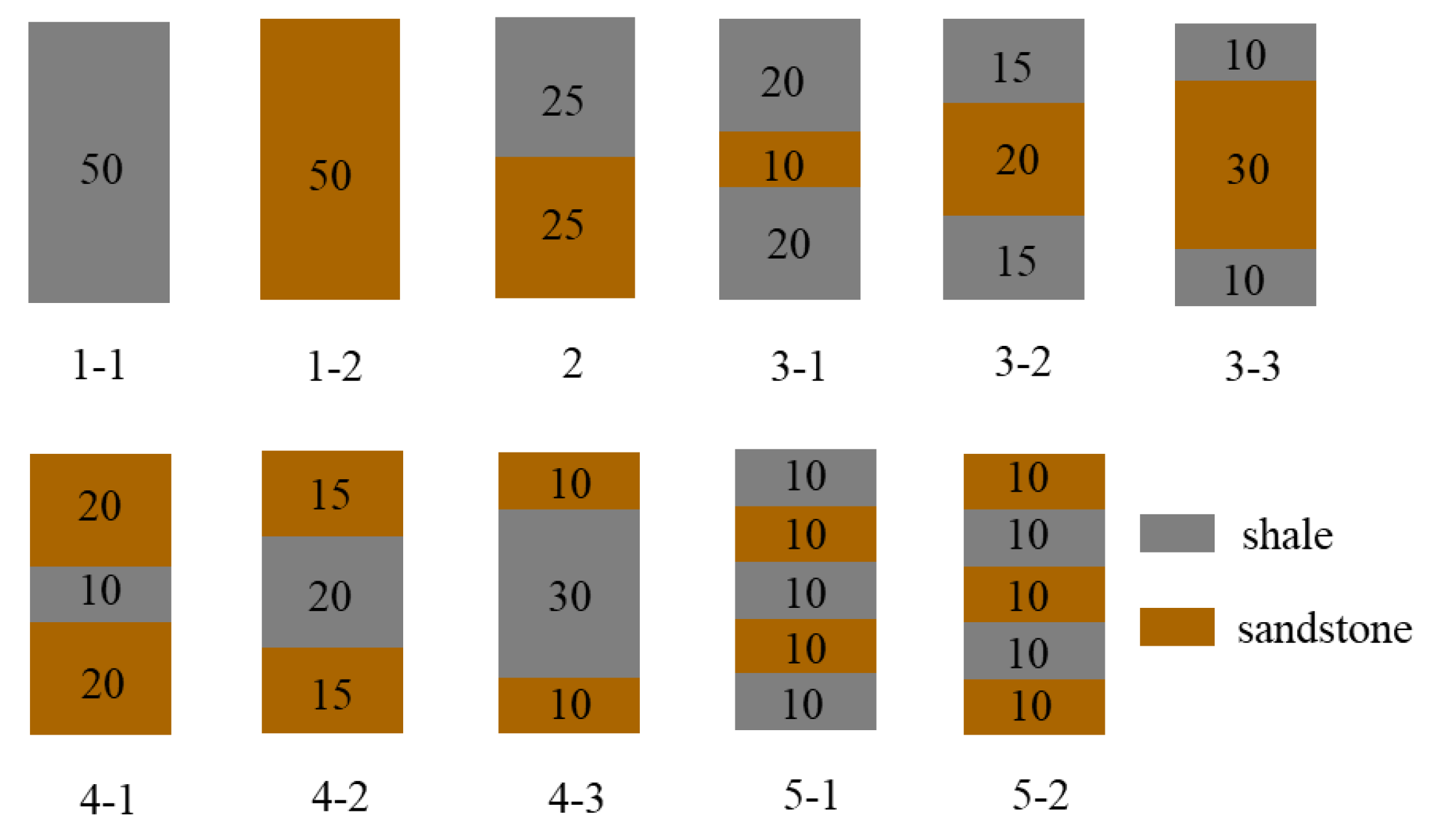
Figure 1. Schematic diagram of sample scheme.
Applsci 13 07537 g001
Figure 2. Comparative analysis of the compressive strength of the combination.
Applsci 13 07537 g002
Figure 3. Strength characteristics of superimposed rock mass.
Applsci 13 07537 g003
Figure 4. Influence of interlayer thickness on the strength of interlayer rock mass.
Applsci 13 07537 g004
Figure 5. Influence of rock position on the strength of the sandwich rock mass.
Applsci 13 07537 g005
Figure 6. The influence of the number of layers on the strength of rock mass.
Applsci 13 07537 g006
Figure 7. Comparison between sandwich type and interbedded type with the same content.
Applsci 13 07537 g007
Figure 8. Analysis diagram of elastic modulus.
Applsci 13 07537 g008
Figure 9. Stress analysis diagram of layered rock mass.
Applsci 13 07537 g009
Figure 10. Influence of the number of layers on the elastic modulus.
Applsci 13 07537 g010
Figure 11. Analysis of combination stress–strain curve.
Applsci 13 07537 g011
Figure 12. Comparative analysis of stress–strain curves.
Applsci 13 07537 g012
Figure 13. Failure characteristics of weak interlayer.
Applsci 13 07537 g013
Figure 14. Failure characteristics of the hard interlayer.
Applsci 13 07537 g014
Figure 15. Failure characteristics of interbedded rock mass.
Applsci 13 07537 g015
Table 1. Uniqueness of each rock.
CategoryTypeCharacteristic
1Single rock massShale and sandstone are sedimentary rocks, whose mechanical characteristics are closely related to structural composition.
2Superimposed rock massIt is composed of two kinds of rock mass with different strength. The thickness of each rock mass is relatively thick, and its mechanical properties are determined by two kinds of components.
3Sandwiched rock massThe sandwiched rock mass has a layered or banded soft (hard) thin layer, and its mechanical properties such as mechanical strength and elastic modulus are smaller (larger) than those of surrounding rock.
4Interbedded rock massThe interbedded rock mass is a kind of sedimentary type in which soft rock and hard rock alternate with each other in longitudinal direction and the thickness is small. The lithology shows frequent vertical alternations between soft and hard.
Table 2. Test results.
GroupingLithologyProportion (H:S)Number of LayersHierarchical FeatureCompressive Strength/MPaModulus of Elasticity/GPa
1-1Shale 1 200.6734.72
1-2Sandstone 1 37.379.66
2Shale-SandstoneAssociation1:12HS40.89.39
3-14:13HSH76.8815.65
3-23:23HSH41.7712.63
3-32:33HSH29.049.14
4-11:43SHS29.646.02
4-22:33SHS48.3410.19
4-33:23SHS67.0510.93
5-13:25HSHSH44.228.89
5-22:35SHSHS48.178.28
Note: H (hard) stands for shale S (soft) stands for sandstone.
Disclaimer/Publisher’s Note: The statements, opinions and data contained in all publications are solely those of the individual author(s) and contributor(s) and not of MDPI and/or the editor(s). MDPI and/or the editor(s) disclaim responsibility for any injury to people or property resulting from any ideas, methods, instructions or products referred to in the content.