
Magnetic Levitation Belt Conveyor Control System Based on Multi-Sensor Fusion


Abstract
:1. Introduction
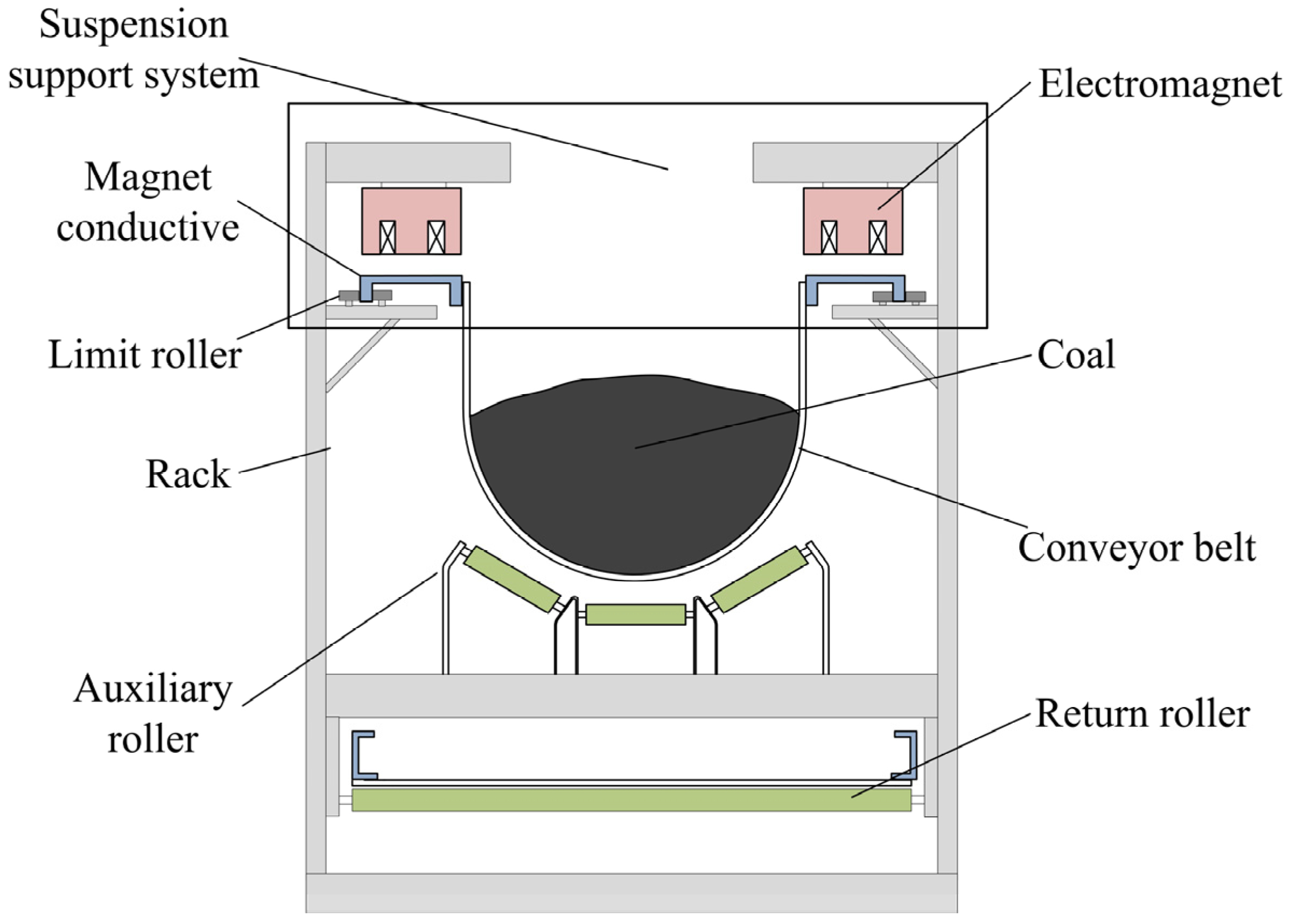
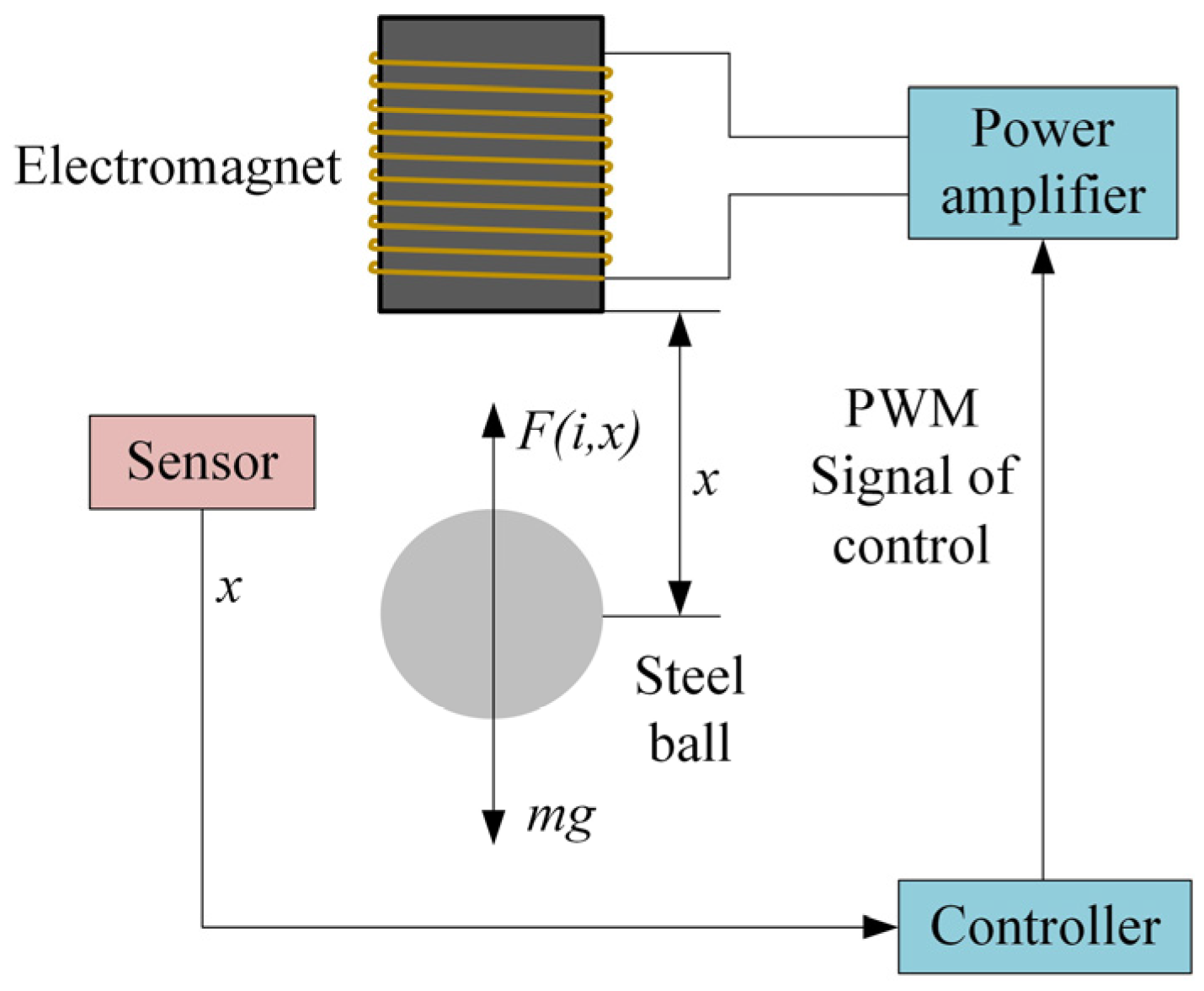
2. System Model
- Neglecting the magnetoresistance in the steel ball and the electromagnet, the magnetoresistance of the magnetic circuit consisting of the electromagnet and the steel ball is concentrated in the suspended air gap.
- The leakage flux is neglected, where the flux passes through the air gap of the external pole of the electromagnet.
- The magnetic flux is uniformly distributed at the air gap, thus neglecting the edge effects.
3. Method
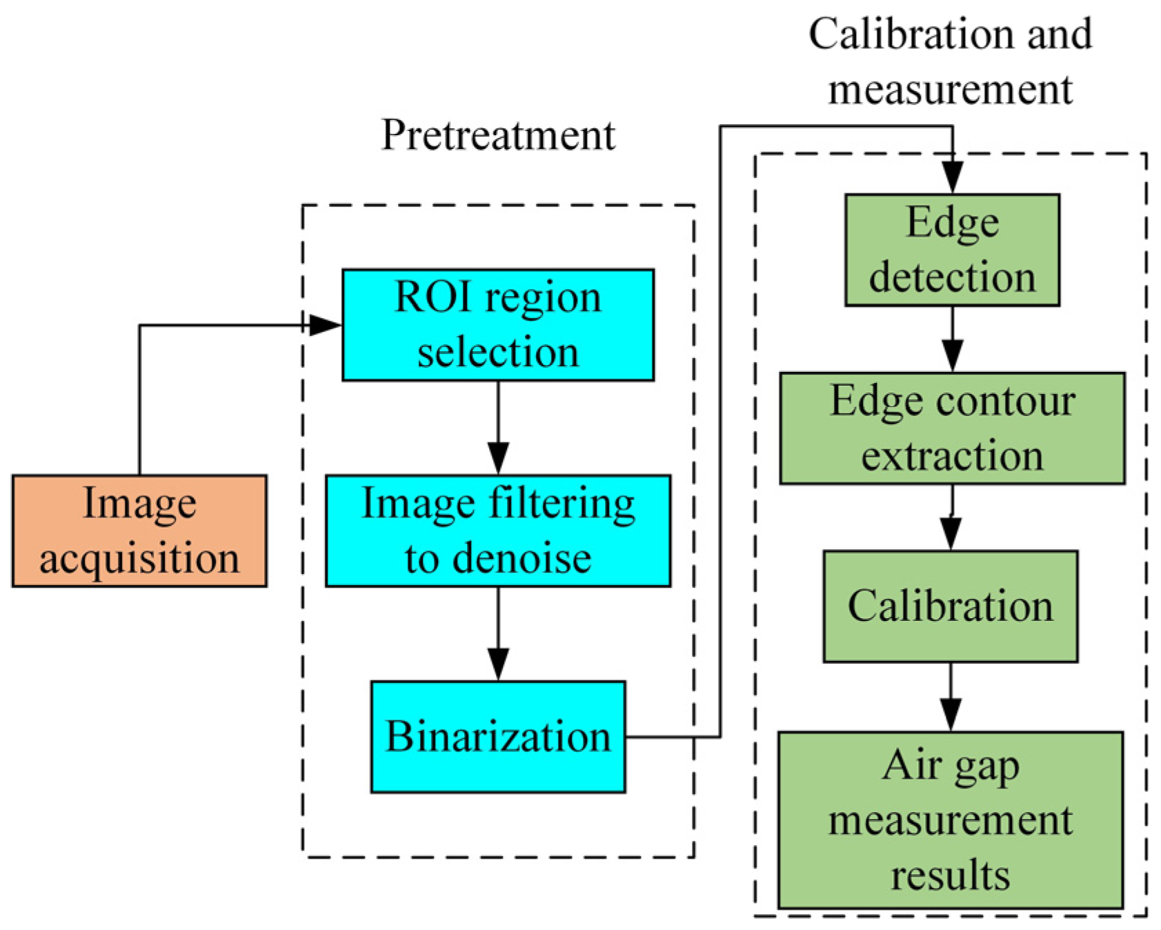
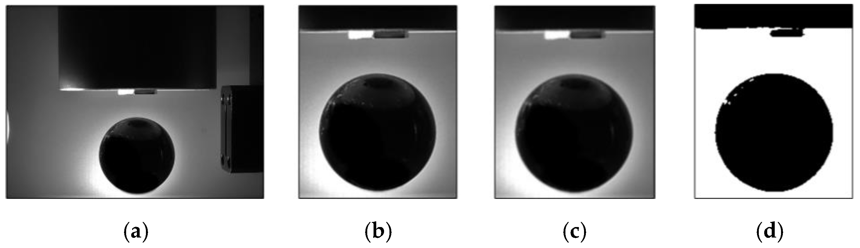
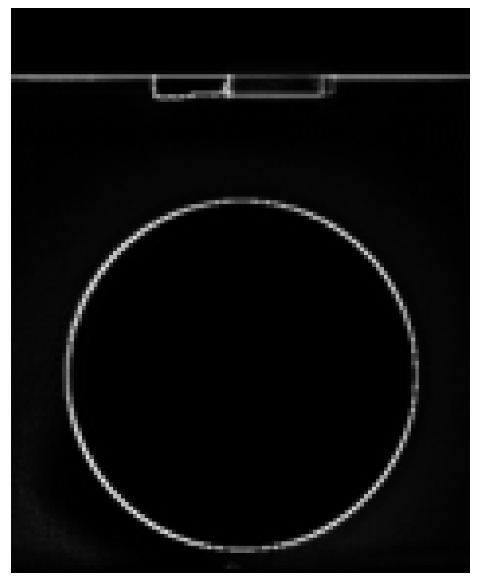
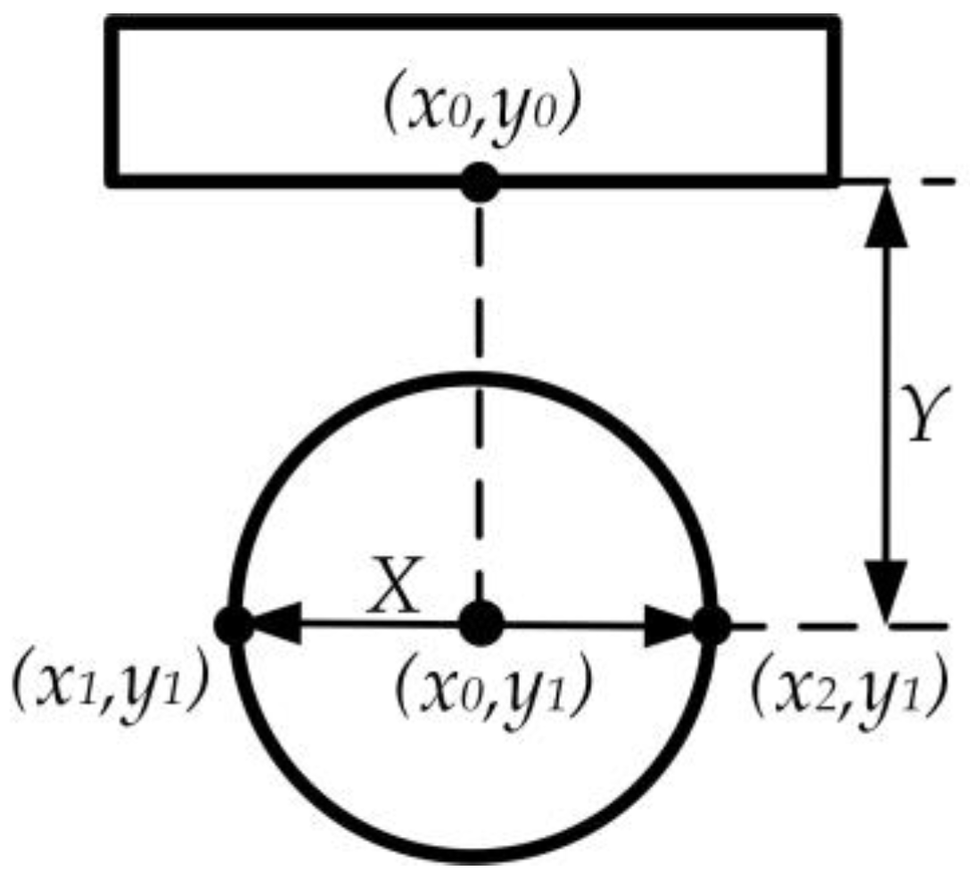
3.1. Industrial Camera Measurement Algorithm
3.2. Extended Kalman Filtering Principle
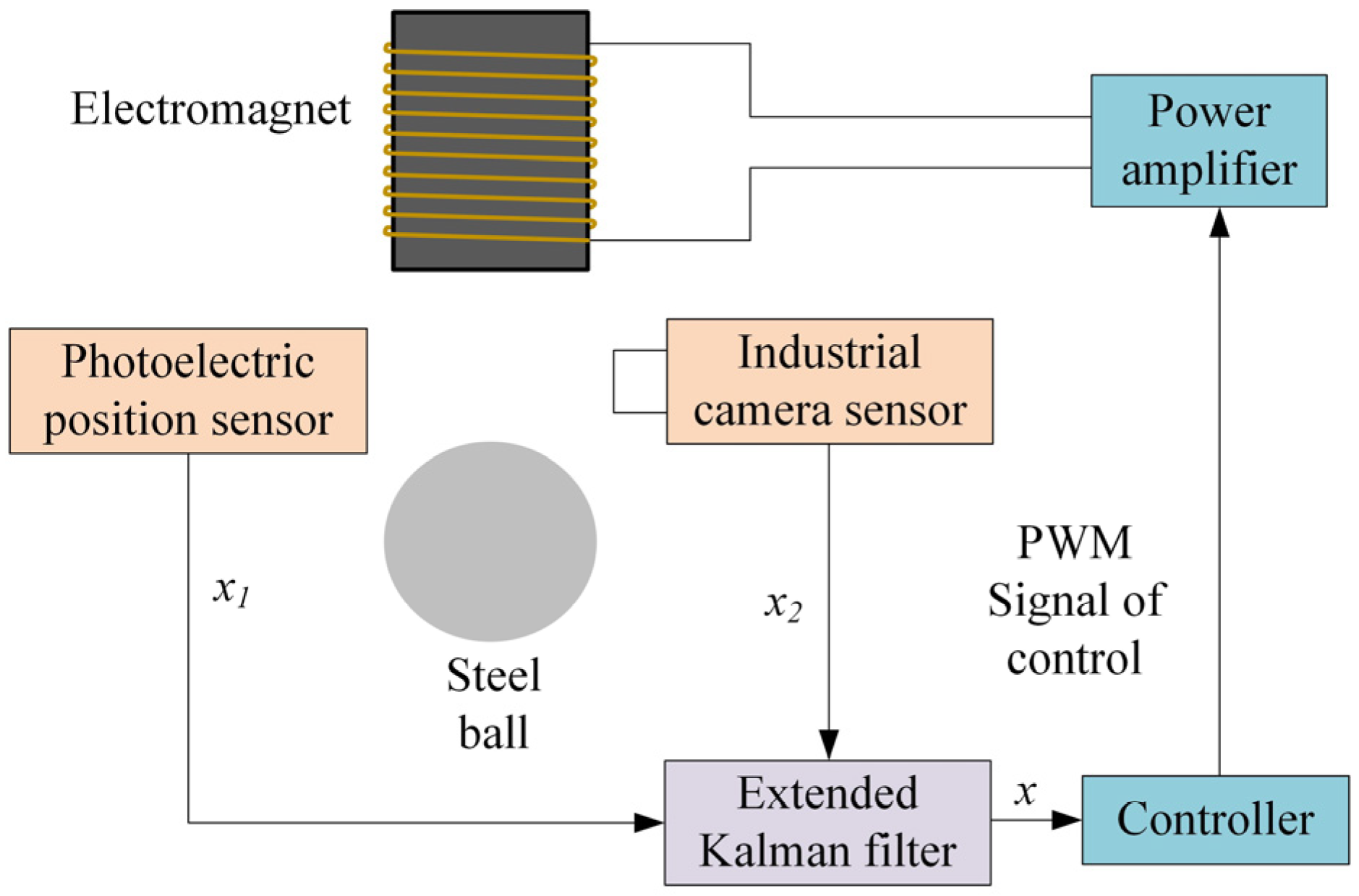
3.3. Multi-Sensor Fusion Algorithm
4. Results and Discussion
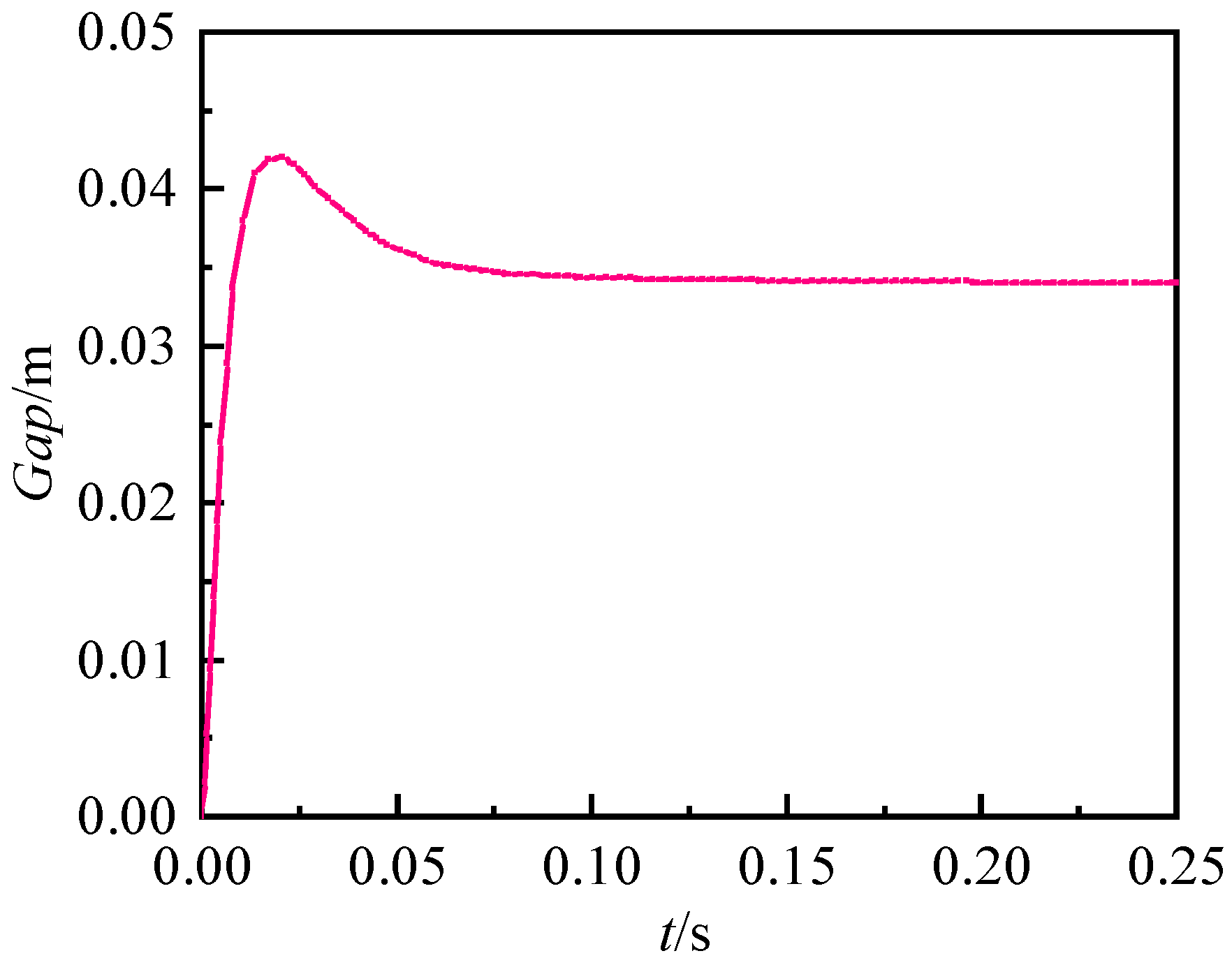
4.1. PID Simulation Analysis
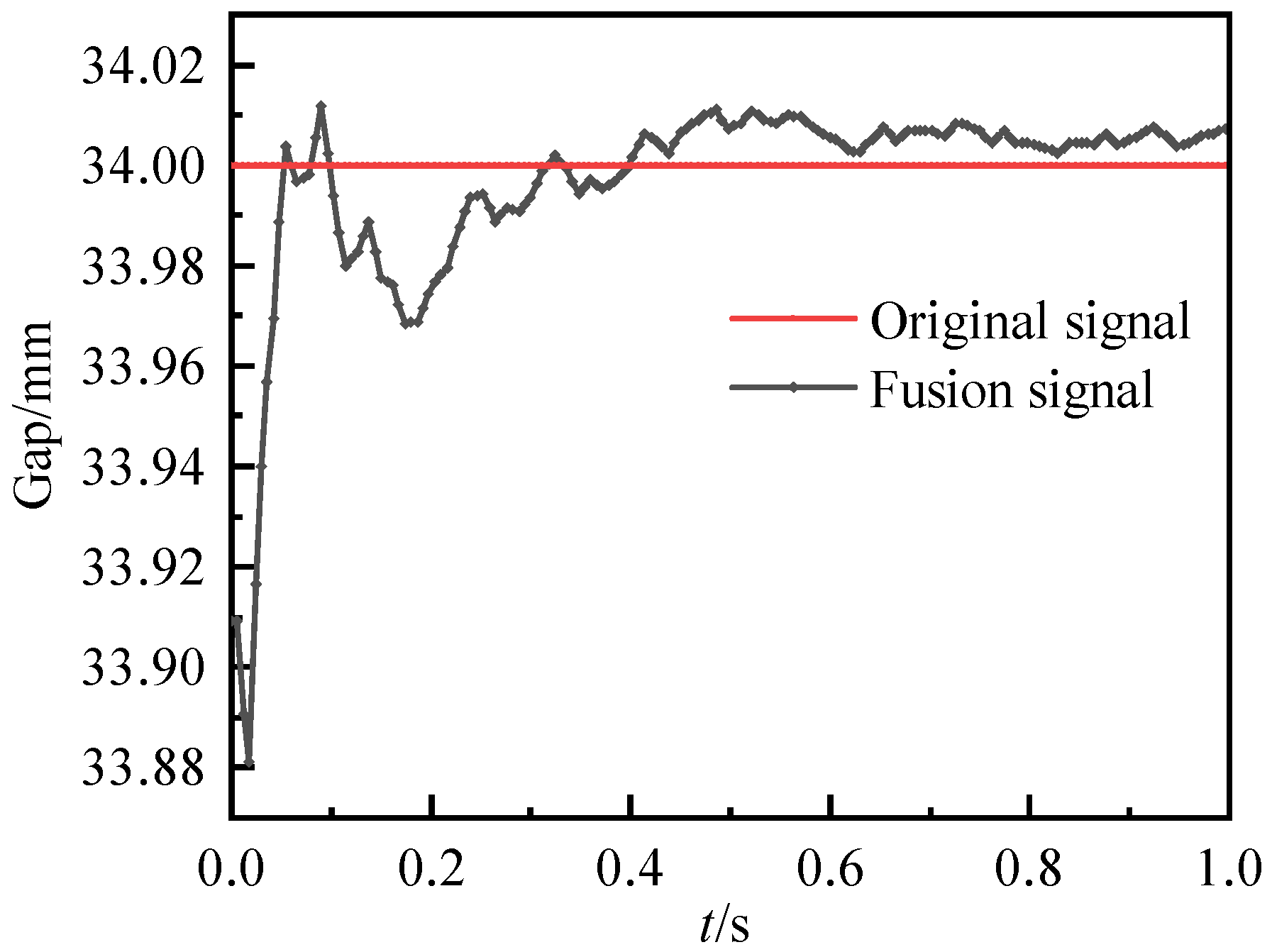
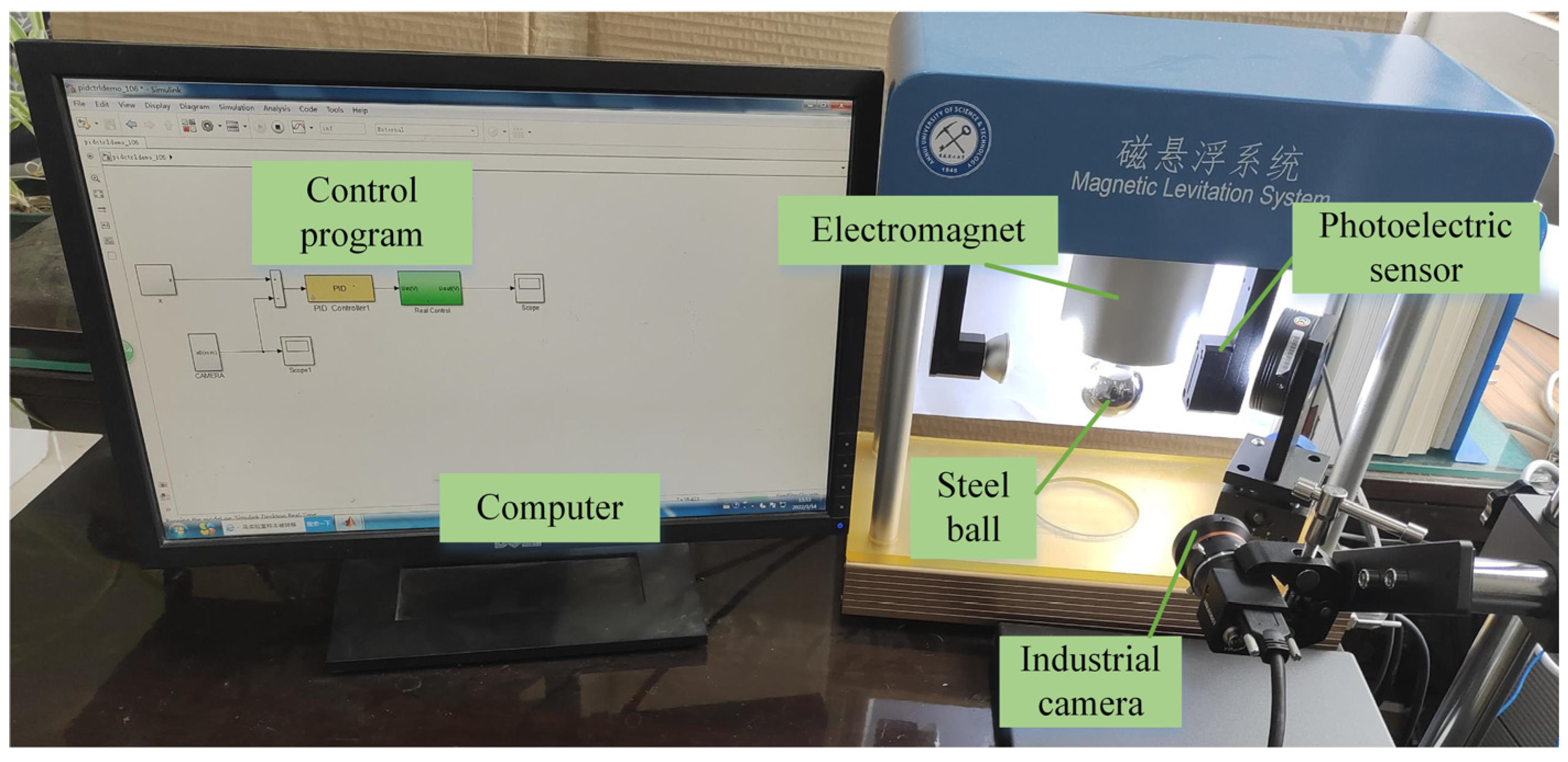
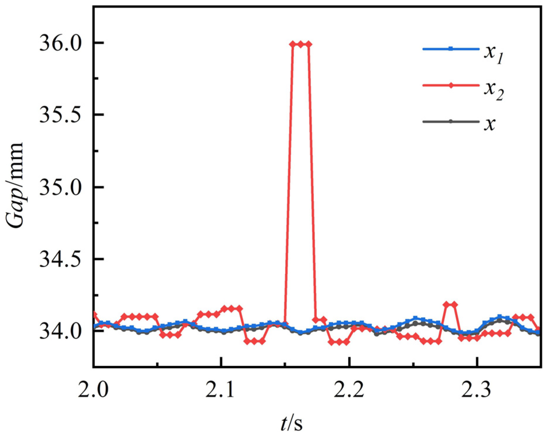
4.2. Experimental Verification
5. Conclusions
- A magnetic levitation air-gap measurement system based on image processing was proposed. By preprocessing, edge detecting, and calibrating industrial camera images, the real suspension air-gap value was obtained, which increased the reliability of the sensor measurement.
- A system model based on multi-sensor fusion was established. The data measured by the two sensors were fused using an extended Kalman filter, and then the control algorithm was used to achieve stable suspension.
- A control test was conducted using a magnetic levitation ball system. The experimental results showed that the data fusion method accurately measured the suspension air gap, and the measurement results were not easily affected by the external environment. The fusion data were more robust, and the suspension system was stably suspended by PID control. It thus met the requirements of maglev control and improved the stability and anti-interference ability of the system.
Author Contributions
Funding
Data Availability Statement
Acknowledgments
Conflicts of Interest
References
- Zhang, S.; Xia, X. Optimal control of operation efficiency of belt conveyor systems. Appl. Energy 2010, 87, 1929–1937. [Google Scholar] [CrossRef]
- Reicks, A.V. Belt conveyor idler roll behaviors. In Bulk Material Handling by Conveyor Belt; SME: Southfield, MI, USA, 2008; Volume 7, pp. 35–40. [Google Scholar]
- Xie, H.K.; Bao, J.S.; Ge, S.R.; Yin, Y.; Xu, H. Experimental research on rotational resistance characteristics of Belt conveyor bearing idler. J. China Coal Soc. 2019, 44, 731–736. [Google Scholar]
- Seo, H.; Lim, J.; Park, S.U.; Mok, H.S. A study on efficiency of magnetic levitation trains using linear induction motor by slip pattern. In Proceedings of the 2019 IEEE Energy Conversion Congress and Exposition (ECCE), Baltimore, MD, USA, 29 September–3 October 2019. [Google Scholar]
- Impinna, F.; Detoni, J.G.; Amati, N.; Tonoli, A. Passive Magnetic Levitation of Rotors on Axial Electrodynamic Bearings. IEEE Trans. Magn. 2012, 49, 599–608. [Google Scholar] [CrossRef]
- Lee, H.-W.; Kim, K.-C.; Lee, J. Review of maglev train technologies. IEEE Trans. Magn. 2006, 42, 1917–1925. [Google Scholar] [CrossRef]
- Bobtsov, A.A.; Pyrkin, A.; Ortega, R.S.; Vedyakov, A.A. A state observer for sensorless control of magnetic levitation systems. Automatica 2018, 97, 263–270. [Google Scholar] [CrossRef]
- Wai, R.-J.; Chen, M.-W.; Yao, J.-X. Observer-based adaptive fuzzy-neural-network control for hybrid maglev transportation system. Neurocomputing 2016, 175, 10–24. [Google Scholar] [CrossRef]
- Wang, H.; Ge, X.; Liu, Y.-C. Second-Order Sliding-Mode MRAS Observer-Based Sensorless Vector Control of Linear Induction Motor Drives for Medium-Low Speed Maglev Applications. IEEE Trans. Ind. Electron. 2018, 65, 9938–9952. [Google Scholar] [CrossRef]
- Chen, S.; Liu, G.; Zheng, S. Sensorless Control of BLDCM Drive for a High-Speed Maglev Blower Using Low-Pass Filter. IEEE Trans. Power Electron. 2016, 32, 8845–8856. [Google Scholar] [CrossRef]
- Kim, S.; Ahn, C.K. Sensorless non-linear position-stabilising control for magnetic levitation systems. IET Control Theory Appl. 2020, 14, 2682–2687. [Google Scholar] [CrossRef]
- Wang, H.; Liu, Y.; Ge, X. Sliding-mode observer-based speed-sensorless vector control of linear induction motor with a parallel secondary resistance online identification. IET Electr. Power Appl. 2018, 12, 1215–1224. [Google Scholar] [CrossRef]
- Zhang, W.Y.; Zhu, H.Q.; Yuan, Y. Study on key technologies and applications of magnetic bearings. J. Trans. China Electrotech. Soc. 2015, 30, 12–20. [Google Scholar]
- Luo, R.C.; Yih, C.C.; Su, K.L. Multisensor fusion and integration: Approaches, applications, and future research directions. IEEE Sens. J. 2007, 2, 107–119. [Google Scholar] [CrossRef]
- Gravina, R.; Alinia, P.; Ghasemzadeh, H.; Fortino, G. Multi-sensor fusion in body sensor networks: State-of-the-art and research challenges. Inf. Fusion 2017, 35, 68–80. [Google Scholar] [CrossRef]
- Wang, Y.; Chen, T.; He, Z.; Wu, C. Review on the machine vision measurement and control technology for intelligent man-ufacturing equipment. Control Theory Appl. 2015, 32, 273–286. [Google Scholar]
- Zhou, B.C.; Lv, J.L.; Xiao, T.Z.; Cui, Z.M. Research status and development trend of machine vision technology. J. Henan Sci. Technol. 2021, 40, 18–20. [Google Scholar]
- Park, J.J.; Kim, J.K.; Lee, E.S.; Lee, M.K. Micro circular path measurement of two-axis stage using a machine vision system and the application. Int. J. Adv. Manuf. Technol. 2011, 56, 1049–1055. [Google Scholar] [CrossRef]
- Chen, Y. Study on development status and application trends of machine vision technology. J. Wirel. Internet Technol. 2018, 15, 147–148. [Google Scholar]
- Zhang, C.H. Design and Implementation of Magnetic Levitation System Experiment Platform Based on Semi-Physical Simula-tion. Master’s Thesis, Southwest Jiaotong University, Chengdu, China, 2020. [Google Scholar]
- Hu, R.; Xiao, D.H.; Bian, J.Y.; He, Z.B.; Chen, J.Q.; Lin, X.S.; Peng, H.G. Research on leveling control method of hydraulic tower based on fuzzy PID. J. Electr. Eng. 2021, 16, 166–173. [Google Scholar]
- Zhang, B.L.; Zhan, Y.H.; Pan, D.W.; Chen, J.; Song, W.J.; Liu, W.T. Vehicle detection based on fusion of millimeter-wave radar and machine vision. J. Automot. Eng. 2021, 43, 478–484. [Google Scholar]
- Rábek, M.; Áková, K. Building of the Fan Driven Ball Levitation System. IFAC-PapersOnLine 2019, 52, 283–287. [Google Scholar] [CrossRef]
- Qin, Y.; Peng, H.; Ruan, W.; Wu, J.; Gao, J. A modeling and control approach to magnetic levitation system based on state-dependent ARX model. J. Process Control 2014, 24, 93–112. [Google Scholar] [CrossRef]
- Smith, S.M.; Brady, J.M. SUSAN—A New Approach to Low Level Image Processing. Int. J. Comput. Vis. 1997, 23, 45–78. [Google Scholar] [CrossRef]
- Zhang, M.; Gunturk, B.K. Multiresolution Bilateral Filtering for Image Denoising. IEEE Trans. Image Process. 2008, 17, 2324–2333. [Google Scholar] [CrossRef] [Green Version]
- Singh, S.; Saurav, S.; Saini, R.; Saini, A.K.; Shekhar, C.; Vohra, A. Comprehensive Review and Comparative Analysis of Hardware Architectures for Sobel Edge Detector. Int. Sch. Res. Not. 2014, 2014, 857912. [Google Scholar] [CrossRef] [Green Version]
- Sikka, P.; Asati, A.R.; Shekhar, C. High-speed and area-efficient Sobel edge detector on field-programmable gate array for arti-ficial intelligence and machine learning applications. Comput. Intell. 2021, 37, S1056–S1067. [Google Scholar] [CrossRef]
- Chao, H.; Youn, B.D.; Chung, J. A multiscale framework with extended Kalman filter for lithium-ion battery SOC and capacity estimation. Appl. Energy 2012, 92, 694–704. [Google Scholar]
- Peng, T.; Jing, Y.; Kong, J.; Hao, J. A Maglev Gap Measurement Method based on Machine Vision. In Proceedings of the 2020 Asia-Pacific Conference on Image Processing, Electronics and Computers (IPEC), Dalian, China, 14–16 April 2020; pp. 135–139. [Google Scholar]


| Parameter Numerical | Value |
|---|---|
| Ball mass m/g | 100 |
| Core diameter/mm | 22 |
| Number of electromagnet turns N | 2450 |
| Amplification factor Ka | 9.776 |
| Sensor coefficient Ks Balance position x0/mm | −467.4 34 |
| Equilibrium position current i0/A | 1.17 |
| Measurement Method | Photoelectric Sensor Value x1 | Industrial Camera Value x2 | Fusion Value x |
|---|---|---|---|
| Root-mean-square error/mm | 0.0374 | 0.0890 | 0.0293 |
Disclaimer/Publisher’s Note: The statements, opinions and data contained in all publications are solely those of the individual author(s) and contributor(s) and not of MDPI and/or the editor(s). MDPI and/or the editor(s) disclaim responsibility for any injury to people or property resulting from any ideas, methods, instructions or products referred to in the content. |
© 2023 by the authors. Licensee MDPI, Basel, Switzerland. This article is an open access article distributed under the terms and conditions of the Creative Commons Attribution (CC BY) license (https://creativecommons.org/licenses/by/4.0/).
Share and Cite
Hu, K.; Jiang, H.; Zhu, Q.; Qian, W.; Yang, J. Magnetic Levitation Belt Conveyor Control System Based on Multi-Sensor Fusion. Appl. Sci. 2023, 13, 7513. https://doi.org/10.3390/app13137513
Hu K, Jiang H, Zhu Q, Qian W, Yang J. Magnetic Levitation Belt Conveyor Control System Based on Multi-Sensor Fusion. Applied Sciences. 2023; 13(13):7513. https://doi.org/10.3390/app13137513
Chicago/Turabian StyleHu, Kun, Hao Jiang, Qinqin Zhu, Wangqian Qian, and Jinhan Yang. 2023. "Magnetic Levitation Belt Conveyor Control System Based on Multi-Sensor Fusion" Applied Sciences 13, no. 13: 7513. https://doi.org/10.3390/app13137513
APA StyleHu, K., Jiang, H., Zhu, Q., Qian, W., & Yang, J. (2023). Magnetic Levitation Belt Conveyor Control System Based on Multi-Sensor Fusion. Applied Sciences, 13(13), 7513. https://doi.org/10.3390/app13137513