1. Introduction
Following the well-known studies carried out by Heyman [
1,
2], the mechanism model was widely used for the limit analysis of stone and masonry arches. Heyman particularized the limit design, developed for steel structures, to masonry arches made of rigid voussoirs that are laid dry without any mortar, with the assumption that the material has no tensile strength, but infinite strength in compression, and that sliding failure cannot occur. The model was developed based on the previous work performed by Kooharian [
3] that pointed out how stone arches fail by forming pin joints, as experimental studies also demonstrated [
4]. The collapse of a stone arch is a geometrical issue rather than a problem of the strength of the material, as is already known from the studies of the eighteenth century performed by eminent scientists, including Couplet, La Hire, Coulomb and Mascheroni.
The limit analysis of voussoir arches was widely applied for the evaluation of stone arch bridges [
5] and often preferred to a more sophisticated analysis [
6,
7,
8,
9,
10] due to its simplicity and speed. The plasticity theorems allowed for the investigation of the collapse mechanisms and the influence of the geometrical and loading parameters on the limit behaviour [
11]. Experimental tests confirmed the expected behaviour [
12,
13].
The mechanism model was also used to analyse the dynamic behaviour of stone arches under seismic actions. Oppenheim [
14] discussed the failure conditions of a circular arch under a horizontal longitudinal acceleration. Clemente [
15] analysed the dynamic behaviour of an arch without backfill under sinusoidal base acceleration and focused on the influence of the frequency content and the amplitude of the input and the initial conditions. Experimental studies conducted on shaking tables confirmed the hypothesis that masonry arches fail by forming pin joints and allowed for the establishment of a correlation between the input acceleration and the damage in the structure [
16].
Successive developments referred to the impact condition during oscillations for a circular arch, in the hypotheses that the hinge locations in the four-link mechanism do not vary, but they reflect when the motion is inverted [
17]. This hypothesis was sometimes considered only for the internal hinges, while two hinges at the springing sections were fixed [
18]. Recently, the dynamic identification of masonry arch bridges was proposed as a support technique to finite element modelling [
19]. Finally, the behaviour of single and multi-span masonry arch bridges under seismic actions was also analysed [
20,
21,
22,
23], and retrofit techniques were proposed [
24,
25,
26].
The effects of an earthquake on an elastic structure are related to the correspondence between the resonance frequencies of the structure and the frequency content of the seismic acceleration at its base. Things are quite different for the model of an arch made of rigid voussoirs. Because of its infinite rigidity, a stone arch does not show any relative motion with respect to its springing points until the amplitude of the external load is sufficient to turn it into a mechanism. When the mechanism is put in action, the arch could return to its natural configuration after some oscillations. From a technical point of view, the ratio between the minimum acceleration necessary to turn the structure into a mechanism and the design peak ground acceleration at the site can be assumed as a safety index. In this way, the safety check of a masonry arch under seismic actions becomes a static issue.
On the basis of these considerations and by using Heyman’s hypotheses, Clemente and Raithel [
27] carried out a detailed analysis of stone voussoir arches under horizontal longitudinal loadings, determining the collapse mechanism and the related load factor. Both the parabolic and circular shapes were considered, subject to their self-weight and backfill.
The most important criticism of Heyman’s model is undoubtedly related to the hypothesis of the infinite compression strength of the material. To overcome this hypothesis, Harvey [
28] proposed the definition of the thrust zone that has a sufficient depth to support the internal forces at each cross-section. Based on empirical observations, Taylor and Mallinder [
29] used a parabolic stress–strain constitutive relationship to describe the local crushing of the masonry at the hinges. Brencich and Di Francesco [
30] developed an iterative procedure for the elastoplastic analysis of a masonry arch with inelastic strains. Crisfield and Packham [
31] proposed a numerical procedure, based on the mechanism method, to evaluate the collapse load of arch bridges with a finite compressive strength of the masonry. Clemente and Saitta [
32] proposed the model of the arch made of no-tension material and with a rigid–perfect plastic behaviour with finite strength in compression. The model was tested by analysing the limit behaviour under vertical and horizontal actions [
33,
34].
In this paper, the model of the arch made of no-tension material and with a rigid–perfect plastic behaviour with finite strength in compression is used for a comprehensive numerical investigation on the limit behaviour of single-span masonry arch bridges under longitudinal seismic actions. The arch is subject to dead loads due to its self-weight and the weight of the backfill, and to a horizontal acceleration acting in the longitudinal direction. This acceleration causes a horizontal inertial loading that acts on the arch. Three different hypotheses about the effects of the inertial actions of the backfill are considered, which are suitable to model the most common situations in practice. The results are given by means of diagrams that can be easily used for a preliminary seismic check of a masonry arch bridge.
The analysis is focused on the onset of motion and the evaluation of the horizontal acceleration necessary to turn the structure into a mechanism. The subsequent dynamic phase is out of the scope of this paper. The influence of the various geometrical and loading parameters is analysed for the case of a plane arch with a parabolic shape. The structural contributions of the spandrel walls and the backfill are not considered in this model. This is a limitation of the model, but it allows the model to operate with a safety advantage.
In order to obtain general results, a very high number of voussoirs is assumed, simulating a continuous model, and disregarding the actual positions of the interface sections and the size of the voussoirs. As a result, the number of possible collapse mechanisms is much higher and, for this reason, the collapse factors obtained are certainly not higher than the actual ones.
2. Limit Domain of a Rectangular Cross-Section with Finite Compression Strength
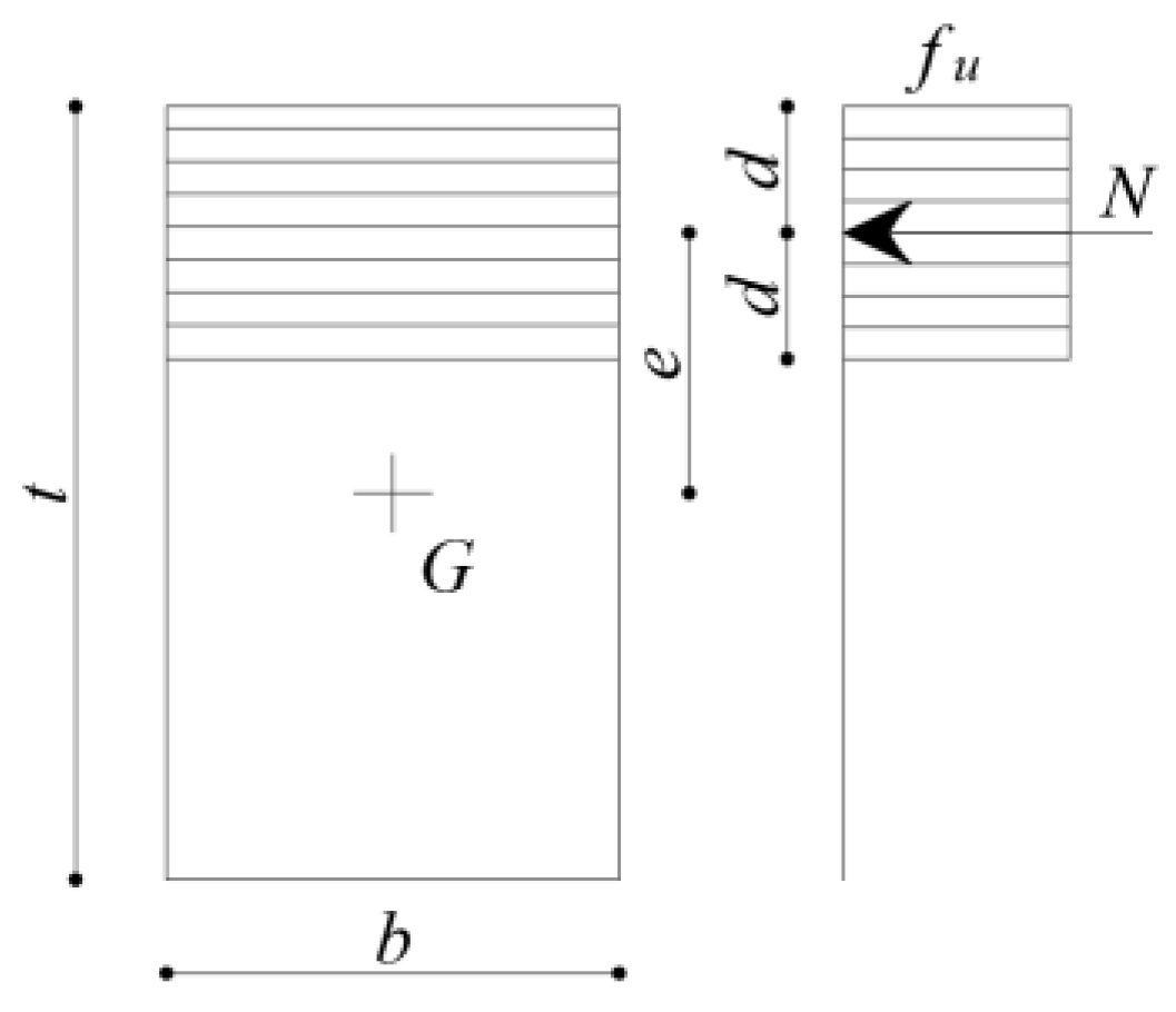
Suppose that the material has no tensile strength but a rigid–perfect plastic behaviour in compression, with a finite compression strength
fu. As a result, on a yielded section subject to an axial force
N acting at a distance
d from the edge, the stresses are uniformly distributed along a distance 2
d from the same edge (
Figure 1).
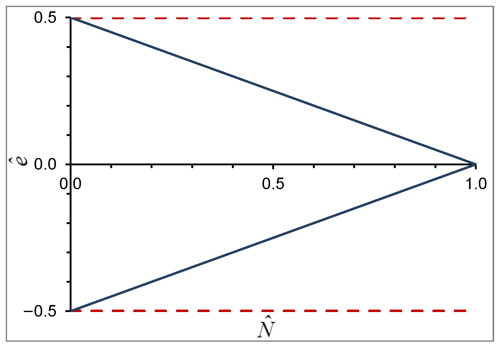
The yield domain of a rectangular cross-section of the thickness
t and width
b can be obtained considering, for each value of 2
d, the corresponding values of the non-dimensional eccentricity
and the axial force
, where
is the ultimate axial force (
Figure 2) as follows:
The couples (
) that define the limit domain correspond to the limit states in which a portion of the cross-section is subject to a constant stress
fu. The section collapses with the formation of a hinge at point
C (
Figure 3). Therefore, the axial force
N does not act at the hinge, but at a distance
d from it.
In
Figure 2, the limit domain for
fu → ∞ is also plotted. In this limit case, the two straight lines are parallel to
axis (their equations become
), and the section collapses with the formation of a hinge at a free edge.
The hypothesis of perfect plasticity must not be deceiving. As will be seen later, the entire compressed portion will have plasticized at the same time, and no large strain will be required. On the other hand, very low (infinitesimal) rotations will be sufficient to define a diagram of virtual displacements.
3. The Limit Analysis under Horizontal Longitudinal Loads
According to the safe theorem, an arch is safe if an equilibrium solution can be found, in which the couples are always inside the limit domain. The failure of an arch occurs when sufficient hinges form to turn it into a mechanism. Due to the hypotheses on the material and the stress distribution, all the hinges form contemporary. The uniqueness theorem states that the solution exists and is unique, and so is the load factor. On the point of collapse, the internal forces acting at the hinge sections contribute to the stability of the arch, while they do not influence the equilibrium in the case of fu → ∞.
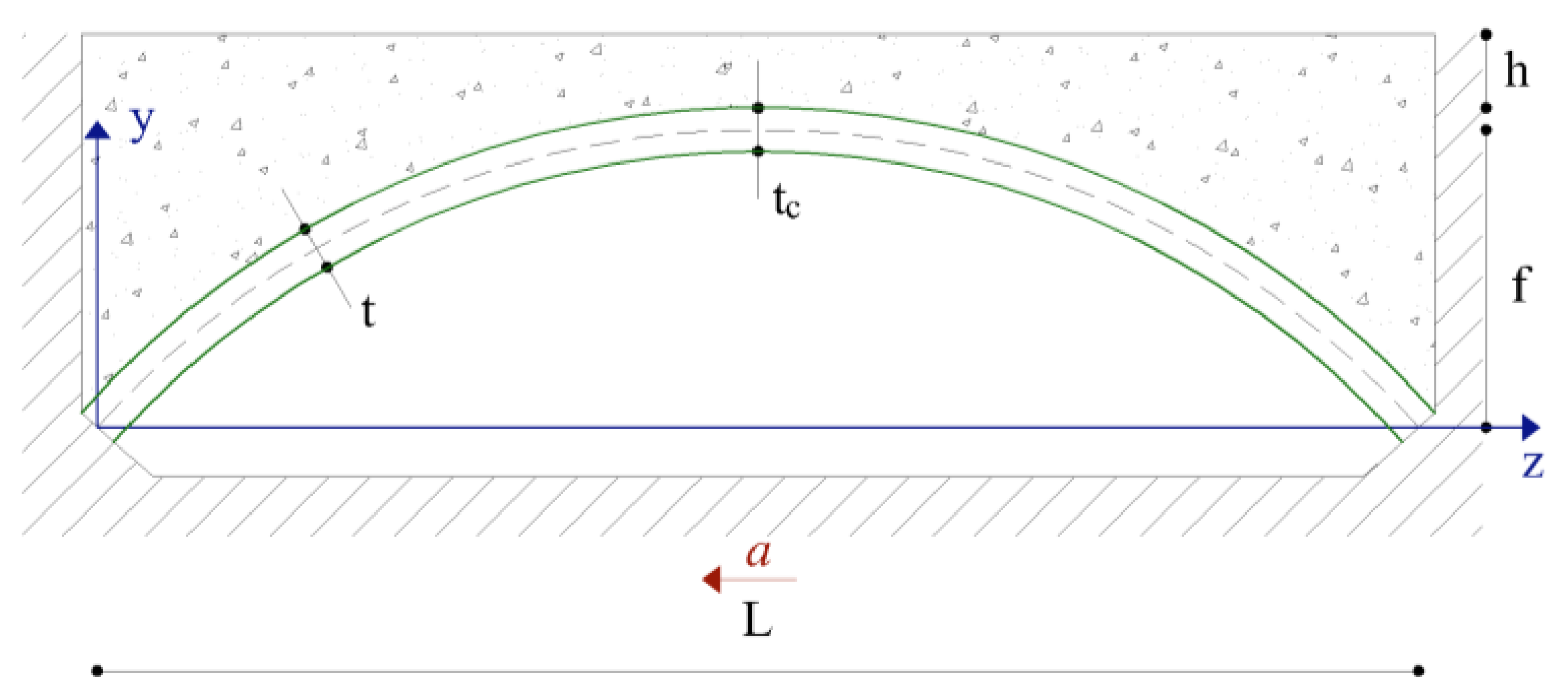
The coordinates of the arch centre line are given in the non-dimensional form as a ratio of the span
L as follows:
The geometrical parameters are also given in the following non-dimensional forms:
The ratio between the sag (or height) and the span;
The ratio between the thickness and the span, where the variable thickness is given as a function of its value at the crown : ( at the crown);
The ratio between the depth of the fill above the crown and the span .
The material compression strength can be represented by the non-dimensional parameter as follows:
where
is the weight per unit volume of the structural material.
The arch is subject to the dead load
, which is given by the summation of the ring self-weight
and the weight
of the backfill, whose weight per unit volume is
. The dead loads per unit span can be written as follows (
= angle between the tangent to the arch centre line and the horizontal axis
z):
The seismic action is represented by the product of the horizontal acceleration
, which is expressed as a fraction of the gravity acceleration
g, acting at the base of both the abutments and the gravity load
associated with the distributed seismic masses as follows:
The load
certainly contains the ring self-weight and the contribution of the backfill, for which different models can be assumed, as will be shown later. It can be written in non-dimensional form as follows:
Then, the distributed seismic load can be written as follows:
All the loads, vertical and horizontal, are evaluated with reference to the centre line of the arch and are supposed to act on it. The infill located over the maximum height of the masonry arch has no effects on the arch in this model; this is acceptable for bridges where h is usually low. Vertical accelerations are not considered; however, in this model, a vertical component of the acceleration is equivalent to a different weight of the permanent load.
Consider the masonry arch in
Figure 4 and suppose that an equilibrium solution under dead loads exists. This means that the points representing the stress states at each cross-section are always within the limit domain (
). When the seismic loads are put in action and increase from zero to the collapse value, the line of thrust changes, and at least four hinges form. On the point of collapse, the thrust line must pass through the hinge points. The collapse mechanism and the corresponding acceleration can be found using the same iteration procedure shown in the case of the vertical travelling load and based on the principle of the virtual works.
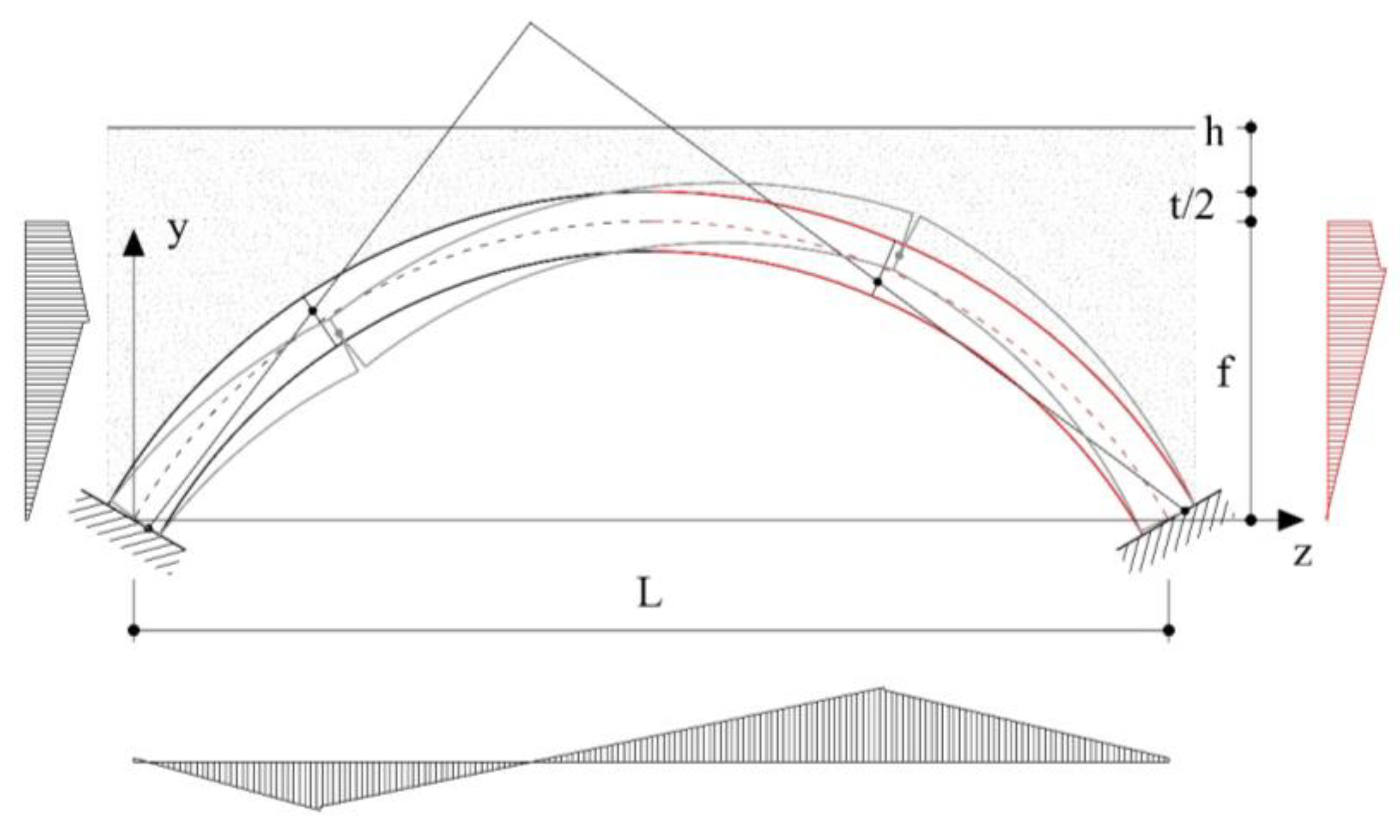
Consider a given mechanism and the corresponding diagrams of the virtual displacement components (
Figure 5). If
are the vertical components of the virtual displacements, the virtual work of dead loads is:
Analogously, if
are the horizontal components of the virtual displacements, the virtual work of the reference seismic load can be written as:
If
are the relative rotations at the
n hinges and
, the internal work is:
It is worth noting that decreases when increases. With being a finite quantity equal to the axial force, when .
In the presence of a horizontal longitudinal seismic acceleration
, expressed as a fraction of the gravity acceleration
g, for an assigned mechanism, the equilibrium equation is
and allows for the determination of a kinematic admissible seismic acceleration:
The upper bound theorem ensures that the collapse acceleration is the minimum of all the kinematic admissible ones, while the lower bound theorem ensures that the collapse acceleration is the maximum of all the statically admissible ones. Considering both these theorems, an iteration procedure can be used, which can be started by assigning a first mechanism and considering the corresponding diagrams of the virtual displacements (
Figure 5). From Equation (13), a kinematically admissible seismic acceleration can be deduced and so the seismic load that corresponds to the assigned mechanism. With the seismic loads being known, it is easy to find out the external reactions and then the line of thrust passing through the yielded zones, i.e., the internal forces acting at each section. The acceleration value is the collapse one only if, for all the sections, the points that represent the stress state are not outside the cross-section limit domain, but they are on the limit domain at a sufficient number of sections to turn the arch into a mechanism. If these conditions are not satisfied, the procedure must be continued, and the hinges must be moved to the sections where there are the maximum distances between the couples (
) and the limit domain, i.e., where the compression stresses are at a maximum, changing the hinge cross-sections and axial force eccentricities.
In the investigation reported in the following, a high number of voussoirs were considered. So, the obtained seismic accelerations that determines the onset of motion are certainly not lower than the actual ones. The latter, in fact, are related to the actual number and size of the voussoirs, which limit the possible mechanisms. Furthermore, by limiting the analysis to a plane model, the width b = 1 was assumed.
4. Seismic Actions Modelling
If the arch is subject to the self-weight only, the horizontal forces are equal to the product between the weight of each voussoir and the horizontal acceleration , and are applied at the gravity centre of each voussoir, i.e., at the same point of the vertical loads. The structure is subject to a load acting along a direction determined by the value of acceleration , as the structure is rigidly rotated in the plane and the springing points are no longer at the same height.
When the backfill is present, the problem is quite complex [
35]. Consider that the arch is subject to a horizontal negative acceleration. Each voussoir is subject to the inertial force due to its own mass, acting at its gravity centre. Three models were considered to simulate the dynamic interaction between the structure and the backfill.
In the first one (M1,
Figure 6), each voussoir of the left half arch (
) is subject to the inertial force due to a horizontal strip of the backfill, acting at its gravity centre. The length of this strip is assumed to be equal to the distance between the arch centre line and the vertical line passing through the left springing of the arch, where the abutment is present. Instead, the backfill on the right half portion (
), subject to its inertial forces, tends to separate from the arch. As a result, the right half structure is subject only to the inertial load due to its own mass. Then, the horizontal seismic loading is as follows:
In the second model (M2,
Figure 6), the left half arch is loaded as in model M1, but the backfill on the right is supposed to be attached to the structure. As a result, the voussoirs of the right half arch are subject to the inertial forces due to a horizontal strip of the backfill and acting at its gravity centre. The length of this strip is assumed to be equal to the distance between the centre line and the vertical line passing through the right springing. In this case, the horizontal seismic loading is as follows:
In the third model (M3,
Figure 6), each voussoir is subject to a horizontal force proportional to the vertical load acting on it; so, the horizontal seismic loading is as follows:
The first model M1 is the most realistic in the case of a continuous backfill composed of material with mechanical characteristics lower than those of the ring material. Model M2 represents the opposite limit case with respect to M1. Model M3 can represent well the case in which a secondary superstructure, usually made of shorter arches, transfer the vertical loads and also the horizontal ones to the main arch by means of a limited number of vertical columns or walls.
It is worth noting that in M2 and M3, the seismic load is antisymmetric with respect to the vertical line passing through the crown. As is well known, this load condition represents the most dangerous load for an arch. Instead, in M1, the seismic load can be seen as the combination of a symmetric load of intensity and an antisymmetric load of intensity ±. Therefore, one could expect that models M2 and M3 give collapse acceleration values lower than M1.
5. Features of the Seismic Limit Behaviour of Masonry Arches
Consider a masonry with a parabolic shape and with the geometrical and weight characteristics varying in the following ranges, respectively:
The parameter σ defines the material characteristics. Its technical range is between 5 and 50; values of σ that are higher than 50 provide results very close to .
In order to analyse the influence of each parameter on the limit behaviour, an arch characterized by their average values was first considered as follows: = 0.2, = 0.05 and = 0.5 (“Mi 0.2 0.05 0.50” in the figures, with i = 1, 2, 3). This is addressed as the “reference arch” in the following. Then, the limit values of the defined technical ranges were considered for each parameter.
For the reference arch, in
Figure 7, the abscissas of the sections where the hinges
Hi (
i = 1, …,4) form are plotted versus σ, for the three models M1, M2 and M3. As one can see, very similar values were obtained for all the models. In
Figure 8, the variability of the hinge locations is shown for different values of
(
Figure 8a),
(
Figure 8b) and
(
Figure 8c). Very similar diagrams were obtained for M2 and M3. The locations of the hinges are almost constant for the three structure–backfill interaction models and are influenced very few by
,
and
, as well as by σ. Furthermore, H1 and H4 almost always form at the springing. Some exceptions can be seen for the limit cases of
= 0.1 for H2 and H3, and
= 0.4 for H4. This occurrence suggests first looking for the hinge cross-sections relative to the simpler case of infinite compression strength and then proceeding with the iteration procedure modifying the positions of the rotation points at each hinge cross-section and, if necessary, the hinge cross-sections. The knowledge of the hinge location is also important for the design of a retrofit intervention, for example, by means of FRP [
36].
The horizontal longitudinal acceleration that brings the arch to the collapse increases with σ up to an asymptotic value, corresponding to the hypothesis of infinite strength. For low values of σ, the collapse acceleration values
are significantly lower than the asymptotic ones, and this reduction is significant in the technical range of σ. In
Figure 9, the values of
are plotted, versus σ for the three models of the structure–backfill interaction, M1, M2 and M3. As one can see, M1 gives values of the longitudinal acceleration higher than M2 and M3, which give very similar values. In
Figure 10, the influences of
and of
and
are shown for M1 (
Figure 10a,b), M2 (
Figure 10c,d) and M3 (
Figure 10e,f), respectively. The influence of
is quite limited;
decreases by about 15% when
varies from its minimum (0.25) to its maximum (1.0) value. Much more significant is the variation of
due to the change in
;
increases by about 65% when
varies from its minimum (0.03) to its maximum (0.07) value. Finally,
increases significantly when
decreases; furthermore, for
= 0.1, the acceleration
increases very much with σ.
In
Figure 11, the distance
d of
N from the edge at the yielded sections is plotted versus σ for the reference arch for the three models M1, M2 and M3. It is seen that
d decreases when σ increases. The difference between the three models M1, M2 and M3 are negligible. In
Figure 12, with reference to M1, the values of
d/t are plotted versus σ for different values of
(
Figure 12a,b),
(
Figure 12c,d) and
(
Figure 12e,f). It is interesting to observe the influence of
and
on the different hinges. At H1,
d increases with
; at H2, it does not seem to be influenced by
; at H3 and H4,
d decreases when
increases. At H4, the values of
d are much higher than those at the other hinges. Analogously, at H1 and H2,
d decreases when
increases; at H3, it does not seem to be influenced by
; at H4,
d increases with
. For all hinges,
d/t increases with
.
The position of the axial forces at the hinges and the position of the rotation points influence the contribution of the internal work to the equilibrium. In
Figure 13, the non-dimensional virtual works (
,
and
) are plotted for the reference arch for the three models. The differences between M1, M2 and M3 are not very significant. In
Figure 14,
Figure 15 and
Figure 16, the influences of
and of
and
on the virtual works are shown for M1 (
Figure 14a,b), M2 (
Figure 15a,b) and M3 (
Figure 16a,b). As is well known, the dead loads have a stabilizing effect with
Lw being negative. The contribution of the internal load
Li is significant only for a low value of
σ. When
σ increases,
Li decreases and tends to be zero. The influence of
on the values of the virtual works is lower than those of
and
.
6. Conclusions
The limit behaviour of the arch bridges made of no-tension material but rigid–perfect plastic behaviour in compression, under seismic horizontal longitudinal action, was analysed in this paper. With this assumption, a relative rotation can occur around an internal point at a hinge section, which coincides with the starting point of the constant stress diagram. The internal work is present at the hinge sections and, with the work of the dead loads, contributes to balance the motor work of the seismic actions.
A non-dimensional formulation was used for a comprehensive numerical investigation. This allowed for the analysis of the arch behaviour for the different values of its material and geometrical characteristics.
In the presence of a horizontal acceleration, each voussoir is subject to the inertial force due to its own mass, acting at its gravity centre. Three models were considered to simulate the dynamic interaction between the structure and the backfill. In the first one (M1), only the voussoirs of the left half portion of the arch are subjected to the inertial force due to a horizontal strip of the backfill. In the second one (M2), the right half arch is also loaded by the inertial force due to a horizontal strip of the backfill, which is the same as the left one. In the last model (M3), each voussoir is subject to a horizontal force proportional to the vertical load acting on it.
The first model, M1, simulates well the case of backfill made of loose soil. M2 is recommended if the backfill material has better mechanical characteristics or is bound to the arch. Finally, M3 represents well the situation of a secondary superstructure, usually made of shorter arches, that transfer the vertical loads and the horizontal ones to the main arch by means of a limited number of vertical columns or walls. M2 and M3 are both antisymmetric loadings; therefore, they provide collapse acceleration values lower than M1.
The most important features of the limit behaviour of the masonry arch bridges under seismic longitudinal actions are as follows:
The locations of the four hinges H1, H2, H3 and H4, whose knowledge is also important for the design of a retrofit intervention, are almost constant for the three models of the structure–backfill interaction and are not very influenced by , and , as well as by σ.
The horizontal longitudinal acceleration that brings the arch to the collapse increases with σ up to an asymptotic value, corresponding to the hypothesis of the infinite compression strength. The values of the acceleration are significantly lower than the asymptotic ones for low values of σ, and this reduction is significant in the technical range of σ.
The influence of on the value of is quite limited; instead, the influence of and is much more significant. The collapse acceleration increases with but decreases when or increases.
The distance d of N from the free edge at the yielded sections decreases when σ increases, but it is influenced in different ways by and at the different hinge sections. The influence of the structure–backfill interaction model on the distance d is negligible.
Author Contributions
Conceptualization, P.C., F.S., G.B. and C.O.; methodology, P.C., F.S., G.B. and C.O.; software, P.C., F.S., G.B. and C.O.; validation, P.C., F.S., G.B. and C.O.; formal analysis, P.C., F.S., G.B. and C.O.; investigation, P.C., F.S., G.B. and C.O.; resources, P.C., F.S., G.B. and C.O.; data curation, P.C., F.S., G.B. and C.O.; writing—original draft preparation, P.C., F.S., G.B. and C.O.; writing—review and editing, P.C., F.S., G.B. and C.O.; visualization, P.C., F.S., G.B. and C.O.; supervision, P.C., F.S., G.B. and C.O.; project administration, P.C.; funding acquisition, P.C. All authors have read and agreed to the published version of the manuscript.
Funding
This paper was prepared in the framework of the European project ARCH-Advancing Resilience of historic areas against Climate-related hazards and other Hazards. This project received funding from the European Union’s Horizon 2020 research and innovation program under grant agreement No. 820999. The sole responsibility for the content of this publication lies with the authors. It does not necessarily represent the opinion of the European Union. Neither the EASME nor the European Commission are responsible for any use of the information contained therein.
Institutional Review Board Statement
Not applicable.
Informed Consent Statement
Not applicable.
Data Availability Statement
Not applicable.
Conflicts of Interest
The authors declare no conflict of interest.
References
- Heyman, J. The stone skeleton. Int. J. Solids Struct. 1966, 2, 249–279. [Google Scholar] [CrossRef]
- Heyman, J. The safety of masonry arches. Int. J. Mech. Sci. 1969, 11, 363–385. [Google Scholar] [CrossRef]
- Kooharian, A. Limit Analysis of Voussoir (Segmental) and Concrete Arches. J. Am. Concr. Inst. 1952, 24, 317–328. [Google Scholar]
- Pippard, A.J.S.; Tranter, E.; Chitty, L. The mechanics of the voussoir arch. J. Inst. Civ. Eng. 1936, 4, 281–306. [Google Scholar] [CrossRef]
- Gilbert, M.; Valentino, J.; Smith, C.; Protchard, T. Limit Analysis of Masonry Arch Bridges Using Discontinuity Layout Optimization. In Structural Integrity, Proceedings of the ARCH 2019, Porto, Portugal, 2–4 October 2019; Arêde, A., Costa, C., Eds.; Springer: Cham, Switzerland, 2019; Volume 11, pp. 307–314. [Google Scholar] [CrossRef]
- Aydin, A.C.; Özkaya, S.G. The finite element analysis of collapse loads of single-spanned historic masonry arch bridges (Ordu, Sarpdere Bridge). Eng. Fail. Anal. 2018, 84, 131–138. [Google Scholar] [CrossRef]
- Zampieri, P.; Perboni, S.; Tetougueni, C.D.; Pellegrino, C. Different Approaches to Assess the Seismic Capacity of Masonry Bridges by Non-linear Static Analysis. Front. Built Environ. 2020, 6, 47. [Google Scholar] [CrossRef]
- Pelà, L.; Aprile, A.; Benedetti, A. Comparison of seismic assessment procedures for masonry arch bridges. Constr. Build. Mater. 2013, 38, 381–394. [Google Scholar] [CrossRef]
- Gönen, S.; Soyöz, S. Seismic analysis of a masonry arch bridge using multiple methodologies. Eng. Struct. 2020, 226, 111354. [Google Scholar] [CrossRef]
- George, J.; Menon, A. Simplified Performance Assessment for Single-Span Masonry Arch Bridges under Live Load. J. Bridg. Eng. 2021, 26, 06021005. [Google Scholar] [CrossRef]
- Clemente, P.; Occhiuzzi, A.; Raithel, A. Limit Behaviour of Stone Arch Bridges. J. Struct. Eng. 1995, 121, 1045–1050. [Google Scholar] [CrossRef]
- Oliveira, D.V.; Maruccio, C.; Lourenco, P.B. Numerical modelling of a load test on a masonry arch bridge. In Proceedings of the 5th International Conference on Arch Bridges ARCH’07, Madeira, Portugal, 12–14 September 2007; Lourenço, P.B., Oliveria, D.V., Portela, A., Eds.; Multicomp Lda: Mem Martins, Portugal, 2007; pp. 577–584. [Google Scholar]
- Page, J. 36—The performance of masonry arch bridges. In The Life of Structures; Armer, G., Clarke, J., Garas, F., Eds.; Butterworth-Heinemann: Oxford, UK, 1989; pp. 318–326. [Google Scholar] [CrossRef]
- Oppenheim, I.J. The masonry arch as a four-link mechanism under base motion. Earthq. Eng. Struct. Dyn. 1992, 21, 1005–1017. [Google Scholar] [CrossRef]
- Clemente, P. Introduction to dynamics of stone arches. Earthq. Eng. Struct. Dyn. 1998, 27, 513–522. [Google Scholar] [CrossRef]
- Clemente, P.; Baratta, A.; Buffarini, G.; Rinaldis, D. Changes in the dynamic characteristics of a masonry arch subjected to seismic actions. In Proceedings of the 4th European Conference on Structural Dynamics EURODYN ‘99, Prague, Czech Republic, 7–10 June 1999. [Google Scholar]
- De Lorenzis, L.; DeJong, M.; Ochsendorf, J. Failure of masonry arches under impulse base motion. Earthq. Eng. Struct. Dyn. 2007, 36, 2119–2136. [Google Scholar] [CrossRef]
- Dejong, M.; De Lorenzis, L.; Adams, S.; Ochsendorf, J. Rocking Stability of Masonry Arches in Seismic Regions. Earthq. Spectra 2008, 24, 847–865. [Google Scholar] [CrossRef]
- Gonen, S.; Soyoz, S. Dynamic Identification of Masonry Arch Bridges Using Multiple Methodologies. In Special Topics in Structural Dynamics & Experimental Techniques, Proceedings of the Society for Experimental Mechanics Series; Epp, D.S., Ed.; Springer: Cham, Switzerland, 2021; Volume 5. [Google Scholar] [CrossRef]
- De Felice, G.; Carbone, I.; Clemente, P. Assessment of multi-span masonry bridges under in-plane seismic actions. In Proceedings of the 8th National Conference on Earthquake Engineering, 8NCEE, San Francisco, CA, USA, 18–22 April 2006; Volume 13, pp. 7875–7884. [Google Scholar]
- Zampieri, P.; Zanini, M.A.; Modena, C. Simplified seismic assessment of multi-span masonry arch bridges. Bull. Earthq. Eng. 2015, 13, 2629–2646. [Google Scholar] [CrossRef]
- Saitta, F.; Clemente, P.; Buffarini, G.; Bongiovanni, G. The Mechanism Method in the Analysis of Two-Span Masonry Arch Bridges. In Structural Integrity, Proceedings of the ARCH 2019, Porto, Portugal, 2–4 October 2019; Arêde, A., Costa, C., Eds.; Springer: Cham, Switzerland, 2019; Volume 11, pp. 289–297. [Google Scholar] [CrossRef]
- Da Porto, F.; Franchetti, P.; Grendene, M.; Ranzato, L.; Valluzzi, M.; Modena, C. Structural capacity of masonry arch bridges to horizontal loads. In ARCH’07, Proceedings of the 5th International Conference on Arch Bridges, Madeira, Portugal, 12–14 September 2007; Lourenço, P.B., Oliveira, D.V., Portela, A., Eds.; Multicomp Lda: Mem Martins, Portugal, 2007; pp. 451–458. [Google Scholar]
- Zampieri, P.; Santinon, D.; Piazzon, R.; Hofer, L.; Toska, K.; Faleschini, F.; Pellegrino, C.; Ricci, D.; Iodice, F.; Vecchi, A.; et al. Intrados CFRCM strengthening of masonry arches. Procedia Struct. Integr. 2023, 44, 926–933. [Google Scholar] [CrossRef]
- Jasieńko, J.; Raszczuk, K.; Frąckiewicz, P.; Kleszcz, K.; Bednarz, Ł. Strengthening of masonry rings with composite materials. Herit. Sci. 2021, 9, 11. [Google Scholar] [CrossRef]
- Buffarini, G.; Clemente, P.; de Felice, G. Retrofitting of masonry arch bridges with FRP. In Proceedings of the 5th International Conference on Structural Analysis of Historical Constructions SAHC’06, New Delhi, India, 6–8 November 2006. [Google Scholar]
- Clemente, P.; Raithel, A. The mechanism model in the seismic check of stone arches. In Arch Bridges: History, Analysis, Assessment, Maintenance, and Repair, Proceedings of the 2nd International Arch Bridge Conference, Venice, Italy, 6–9 October 1998; Sinopoli, A., Ed.; Balkema: Rotterdam, The Netherlands, 1998; pp. 123–129. [Google Scholar]
- Harvey, W.J. Application of the mechanism analysis to masonry arches. Struct. Eng. 1988, 66, 77–84. [Google Scholar]
- Taylor, N.; Mallinder, P.A. The brittle hinge in masonry arch mechanisms. Struct. Eng. 1993, 71, 359–366. [Google Scholar]
- Brencich, A.; De Francesco, U. Assessment of Multispan Masonry Arch Bridges. I: Simplified Approach. J. Bridg. Eng. 2004, 9, 582–590. [Google Scholar] [CrossRef]
- Crisfield, M.A.; Packham, A.J. A Mechanism Program for Computing the Strength of Masonry Arch Bridges; Research Report 124; Transport and Road Research Laboratory (TRRL): Berkshire, UK, 1987. [Google Scholar]
- Clemente, P.; Saitta, F. Analysis of No-Tension Material Arch Bridges with Finite Compression Strength. J. Struct. Eng. 2017, 143, 04016145. [Google Scholar] [CrossRef]
- Saitta, F.; Clemente, P.; Buffarini, G. Analysis of Arch Bridges with Finite Compression Strength Material Under Horizontal Loadings. In Arch Bridges in Culture, Proceedings of the 8th International Conference on Arch Bridges, Wrocław, Poland, 5–7 October 2016; Biliszczuk, J., Bień, J., Hawryszków, P., Kamiński, T., Eds.; DWE Publisher: Wroclaw, Poland, 2016; pp. 991–1000. [Google Scholar]
- Clemente, P.; Saitta, F. Seismic analysis of a two-span masonry arch bridge. In Proceedings of the 17th World Conference on Earthquake Engineering, 17WCEE, Sendai, Japan, 27 September–2 October 2021. 2d-0073. [Google Scholar]
- Sarhosis, V.; Forgács, T.; Lemos, J.V. Modelling Backfill in Masonry Arch Bridges: A DEM Approach. In Proceedings of the ARCH 2019, Porto, Portugal, 2–4 October 2019; Arêde, A., Costa, C., Eds.; Structural Integrity. Springer: Cham, Switzerland, 2020; Volume 11. [Google Scholar] [CrossRef]
- Buffarini, G.; Clemente, P.; de Felice, G.; Satta, A. Limit behaviour of partially reinforced masonry arch bridges. In Proceedings of the 5th Internationnal Conference on Arch Bridges ARCH’07, Madeira, Portugal, 12–14 September 2007; Lourenço, P.B., Oliveira, D.V., Portela, A., Eds.; Multicomp Lda: Mem Martins, Portugal, 2007; pp. 685–692. [Google Scholar]
Figure 1.
Stress distribution in a yielded section.
Figure 1.
Stress distribution in a yielded section.
Figure 2.
Limit domain in the hypothesis of finite compression strength (continuous line) and infinite compression strength (dotted line).
Figure 2.
Limit domain in the hypothesis of finite compression strength (continuous line) and infinite compression strength (dotted line).
Figure 3.
Yielded section; the rotation point is at C.
Figure 3.
Yielded section; the rotation point is at C.
Figure 4.
Structural model of a stone voussoir arch under longitudinal seismic acceleration.
Figure 4.
Structural model of a stone voussoir arch under longitudinal seismic acceleration.
Figure 5.
Collapse mechanism and virtual displacements.
Figure 5.
Collapse mechanism and virtual displacements.
Figure 6.
Models for the seismic actions.
Figure 6.
Models for the seismic actions.
Figure 7.
Hinge locations zHi versus σ for , for the three models M1, M2 and M3.
Figure 7.
Hinge locations zHi versus σ for , for the three models M1, M2 and M3.
Figure 8.
Hinge locations zHi versus σ for M1 (very similar diagrams were obtained for M2 and M3), for different values of (a) , (b) and (c) (the curves are individualized by “Mi ” in the legend).
Figure 8.
Hinge locations zHi versus σ for M1 (very similar diagrams were obtained for M2 and M3), for different values of (a) , (b) and (c) (the curves are individualized by “Mi ” in the legend).
Figure 9.
Horizontal acceleration versus σ for , for the three models M1, M2 and M3 (the curves are individualized by “Mi ” in the legend).
Figure 9.
Horizontal acceleration versus σ for , for the three models M1, M2 and M3 (the curves are individualized by “Mi ” in the legend).
Figure 10.
Horizontal acceleration versus σ for different values of and different values of and , for (a,b) M1, (c,d) M2 and (e,f) M3 (the curves are individualized by “Mi ” in the legend).
Figure 10.
Horizontal acceleration versus σ for different values of and different values of and , for (a,b) M1, (c,d) M2 and (e,f) M3 (the curves are individualized by “Mi ” in the legend).
Figure 11.
Values d/t at the hinges H1, H2, H3 and H4 versus σ for M1, M2 and M3 and for different values of with (the curves are individualized by “Mi” in the legend).
Figure 11.
Values d/t at the hinges H1, H2, H3 and H4 versus σ for M1, M2 and M3 and for different values of with (the curves are individualized by “Mi” in the legend).
Figure 12.
Values of d/t at the hinges versus σ for the extreme values of (a,b) , (c,d) and (e,f) , respectively, for M1 (the curves are individualized by “Mi ” in the legend).
Figure 12.
Values of d/t at the hinges versus σ for the extreme values of (a,b) , (c,d) and (e,f) , respectively, for M1 (the curves are individualized by “Mi ” in the legend).
Figure 13.
Non-dimensional virtual works versus σ for M1, M2 and M3.
Figure 13.
Non-dimensional virtual works versus σ for M1, M2 and M3.
Figure 14.
Virtual works versus σ for (a) different values of and (b) different values of and for M1 (the curves are individualized by “Mi ” in the legend).
Figure 14.
Virtual works versus σ for (a) different values of and (b) different values of and for M1 (the curves are individualized by “Mi ” in the legend).
Figure 15.
Virtual works versus σ for (a) different values of and (b) different values of and for M2.
Figure 15.
Virtual works versus σ for (a) different values of and (b) different values of and for M2.
Figure 16.
Virtual works versus σ for (a) different values of and (b) different values of and for M3.
Figure 16.
Virtual works versus σ for (a) different values of and (b) different values of and for M3.
| Disclaimer/Publisher’s Note: The statements, opinions and data contained in all publications are solely those of the individual author(s) and contributor(s) and not of MDPI and/or the editor(s). MDPI and/or the editor(s) disclaim responsibility for any injury to people or property resulting from any ideas, methods, instructions or products referred to in the content. |
© 2023 by the authors. Licensee MDPI, Basel, Switzerland. This article is an open access article distributed under the terms and conditions of the Creative Commons Attribution (CC BY) license (https://creativecommons.org/licenses/by/4.0/).


