1. Introduction
Tuned mass dampers (TMDs) are mechanical systems that are widely used to reduce the amplitude of dynamic vibrations transmitted by the support to machines or structures in order to guarantee their correct functioning or avoid damages. In the field of construction, a TMD is usually placed on the top floors or on the rooftop of buildings to reduce their swaying due to wind forces. However, the seismic response of buildings can also benefit from TMDs [
1,
2], as they can be used as passive supplemental energy dissipation devices. In this case, the TMD frequency is designed to be tuned with the frequency of the main vibrational mode of the building in order to resonate out of phase with the building structure. Therefore, the effects of the main vibrational mode of the building during seismic behavior are mitigated, and the inertial forces arising in the structural members due to seismic forces are reduced.
In analytical applications, the mechanical behavior of TMDs is represented by a mass connected to the main structure by a spring and a dashpot arranged in parallel. In this schematization, the TMD’s behavior is described by its mass, frequency and damping, which are designed on the basis of the main vibration modes of the building. In these applications, the TMD can be any device that behaves like such a system, e.g., a pendulum with dampers or a concrete slab on rubber isolators.
In the literature, several TMD design methods exist [
3,
4,
5,
6,
7,
8,
9,
10,
11,
12,
13,
14,
15,
16,
17,
18,
19,
20,
21,
22,
23,
24,
25,
26,
27,
28,
29,
30,
31,
32,
33,
34]. Among these, those developed in the last 15 years [
9,
10,
11,
12,
13,
14,
15,
16,
17,
18,
19,
20,
21,
22,
23,
24,
25,
26,
27,
28,
29,
30,
31,
32,
33,
34] propose advanced procedures aiming to optimize the TMD design in order to obtain the highest benefits regarding the seismic response of the building. The most recent design methods either provide formulas coming from closed-form solutions of mechanical models [
10,
11,
12,
13,
14,
15,
16,
17,
18,
19,
20,
21,
22,
23,
24] or consist of genetic algorithms that output the best design parameters [
25,
26,
27,
28,
29,
30,
31]. All these methods focus on the optimization of one or more control parameters characterizing the seismic response of the building equipped with the TMD, e.g., the minimization of the highest floor acceleration or displacement or the maximization of energy dissipated by the TMD. The effectiveness of the design method in reducing the internal forces in structural members is fundamental and depends both on the loads considered in the design process and on the chosen control parameter. Actually, an inadequate design due to, for example, neglecting the soil–structure interaction effects on the building in the TMD design [
21], can cause the plasticization of some structural members, leading to a decrease in the vibration mode frequencies. As a consequence, the resonance between the TMD and the building’s main vibrational modes vanishes, and a detuning of the TMD occurs. Detuning conditions can also arise during the building’s lifespan due to variations in the parameters affecting the vibration frequencies. This occurs when an increase in the building mass or a change in the stiffness occurs due to degradation of the rubber layers in seismic isolators.
Since a correctly designed TMD can remarkably improve the behavior of the structure under horizontal loads, several applications to different types of structures, such as tall buildings, skyscrapers, bridges and wind turbines [
35,
36], have been studied by researchers. However, only a few applications of TMD to existing buildings for their seismic retrofit have been found. These include: the installation of TMD on the top of multi-story buildings sited in Armenia (Assatourians A. and Mehrdoust M. [
37]) to reduce the base shear and the top floor displacements; the roof substitution of the city tower in Rieti, Italy, including a TMD, to increase the vibrational periods and limit the displacements’ amplitude of the tower (Clemente P. [
38]); the application of a TMD on the top of a 13-story building to reduce structural and non-structural damage (Villaverde R. [
39]); the modification of the penthouses of ten buildings in order to make them act as masses of TMDs to reduce the overall seismic demand on structural members (Johnson J. et al. [
40]). Such a limited use of TMDs in the retrofit of existing buildings is probably due to the increase in the building’s total mass and, thus, gravity loads.
In this paper, a case study where a TMD is installed at the top of a medium-rise reinforced concrete (RC) building is presented. The building structure without the TMD was initially designed with dissipative behavior in accordance with the Italian Building Code [
41]. The aim of the TMD application is to modify the structural behavior of the building from dissipative to non-dissipative in order to eliminate reparation or demolition costs after a strong seismic event. In the considered case study, the mass of the TMD was made by an RC slab lying on flat surface sliders (FSSs). Two different solutions are proposed to provide horizontal stiffness and damping to the added system. One involves the use of rubber isolators (RIs), which replace some of the FSSs installed along the perimeter of the roof. The other is based on the use of low = damping rubber isolators (LDRIs) and viscous linear dampers (VLDs) installed along the roof perimeter, together with the FSSs. The design of the TMD was performed in accordance with the procedure described by Christopoulos in [
5]. The effects of the TMD application on the internal forces arising in the structural members will be discussed in comparison with those acting in the original building (OB). The improvement in the building’s structural behavior provided by the TMD is assessed on the basis of the flexural demand over capacity ratios and the energy dissipated by the TMD.
2. Case Study
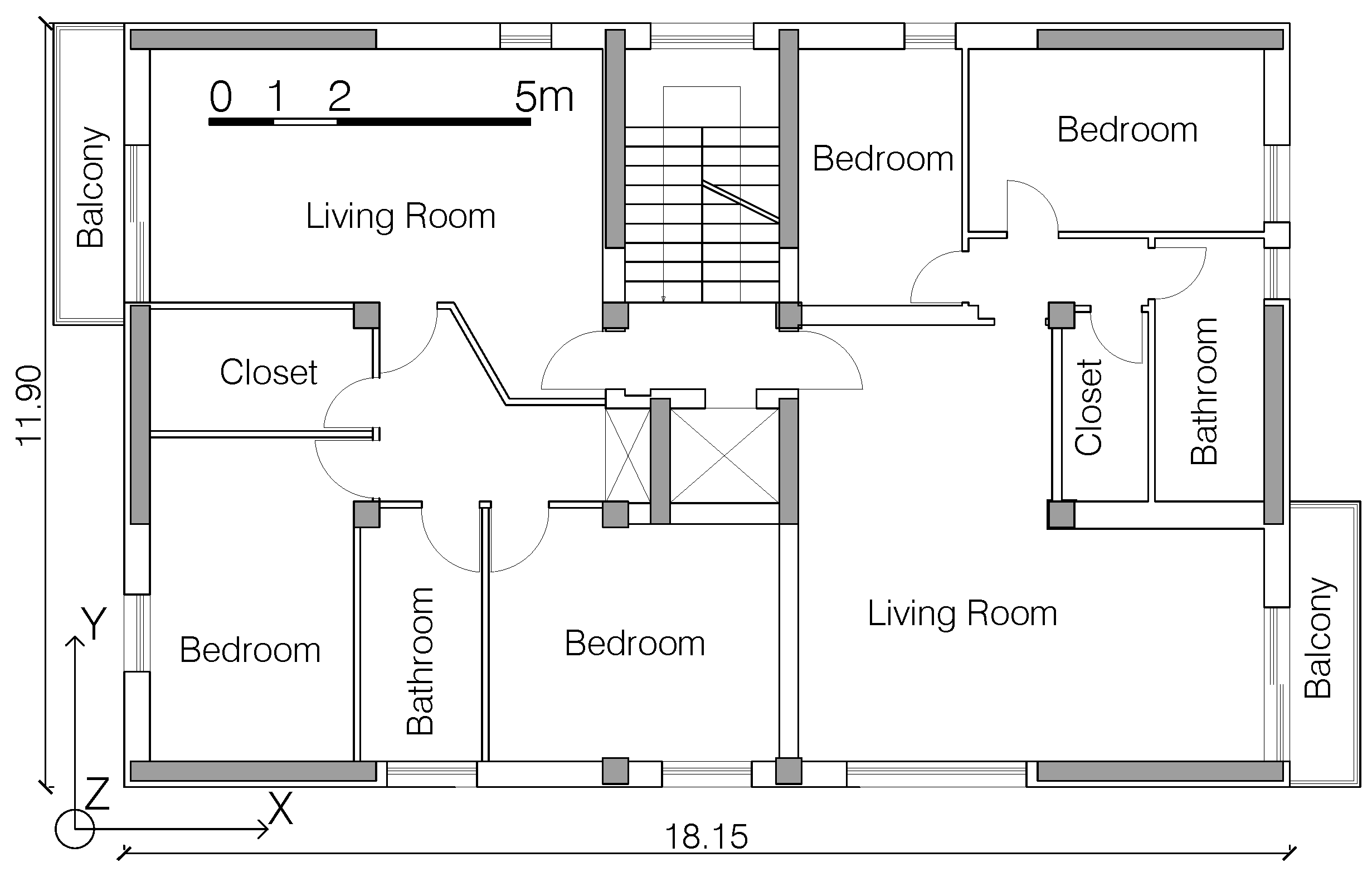
The case study is a six-story residential building located in Tolmezzo, Italy. The building plan is rectangular with dimensions of 18.15 m × 11.90 m (
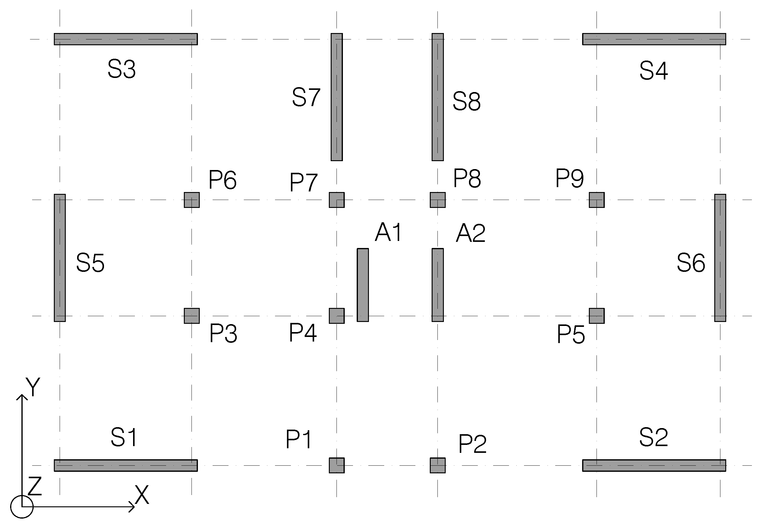
Figure 1) and is the same for all five floors. The interstory height is 3.00 m, except for the ground floor, which is 3.30 m high. The bearing structure against seismic actions is made by RC walls placed along the building perimeter (walls S1–S6 in
Figure 2) and on the sides of the stairwell and the elevator shaft parallel to the
Y direction (S7–S8 and A1–A2 in
Figure 2). The resistance against vertical loads is provided by both walls and columns (P1–P9 in
Figure 2). Columns and walls are connected at floor level by beams oriented along the building’s main directions (
X and
Y in
Figure 1), following the dotted grid in
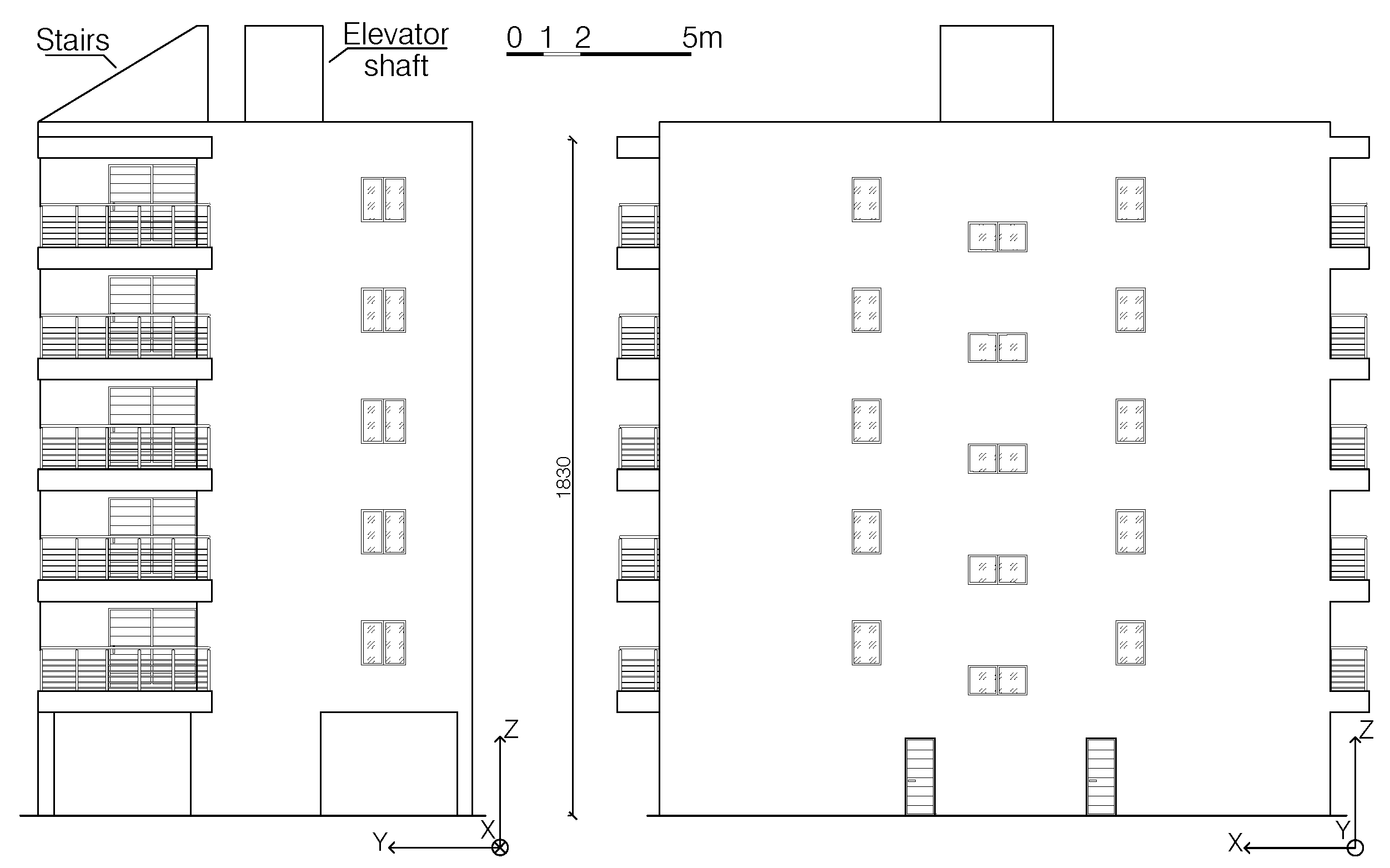
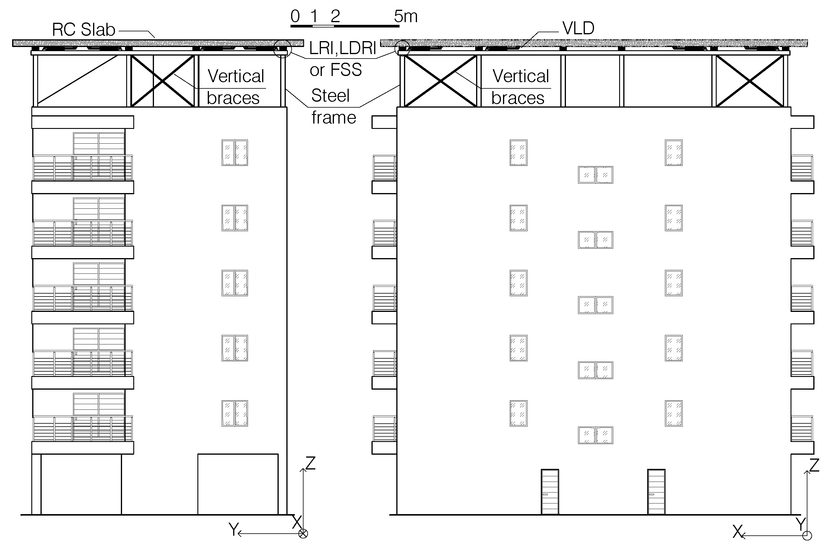
Figure 2. Walls S7–S8, A1–A2 rise above the flat rooftop, as shown in
Figure 3, to allow the access to the roof and the housing of the elevator technical compartment. According to the dimensions shown in
Figure 1 and
Figure 3, the slenderness of the building is calculated as the ratio between the building’s height and the width of its base, which is equal to approximately 1 in the
X direction and 1.5 in the
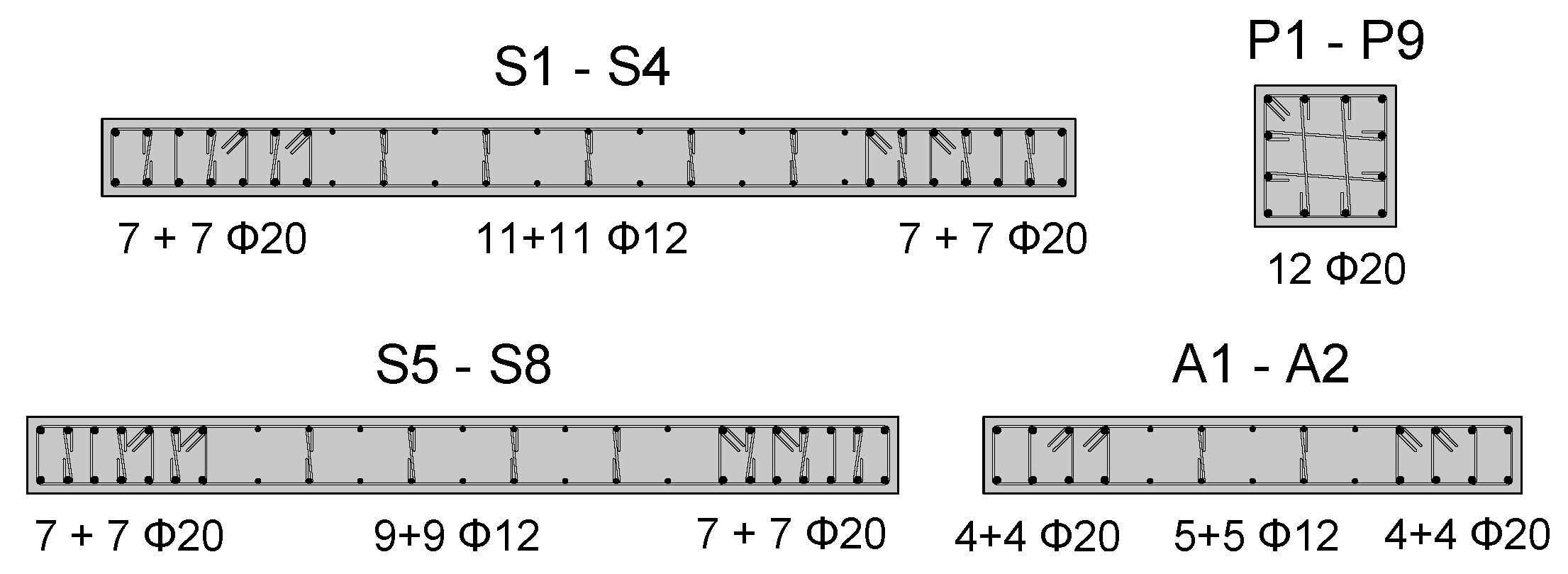
Y direction. A building can be considered a skyscraper if this ratio is at least almost 10. Hence, the considered case study falls in the range of medium- or even low-rise buildings. The cross-sections of vertical elements stay the same for all the storys; only the walls’ longitudinal reinforcements are reduced from the fourth floor upward, where steel bars of diameter
change to
. The dimensions of structural members cross-sections are shown in
Table 1. The reinforcement layouts at the base of vertical elements are shown in
Figure 4. Floors are made by RC joists with a depth of 20 cm, a 5 cm thick RC slab at the top, and hollow bricks as lightening elements. The building foundations are made of a RC slab with dimensions of 19.15 m × 12.90 m × 0.80 m. The materials used for the building design are concrete of Italian grade
, with characteristic compressive strength
= 35 MPa and Young’s modulus
= 34 GPa, and reinforcing steel of Italian grade
, with characteristic yield strength
= 450 MPa and Young’s modulus
= 210 GPa. Both concrete and steel are assumed to be linear materials in the finite element model of the building.
The design of the RC structure against seismic actions was performed according to the dissipative behavior required by the Italian Building Code [
41] for ductile wall structures, corresponding to a behavior factor
. The finite element model (FEM) of the building was made using the software SAP2000 [
42]. Beams and columns were modeled through frame elements, while shell elements were used for wall modeling (
Table 1). Floors were assumed to behave as rigid diaphragms. The effects of cracking on structural members were taken into account by reducing the shear and flexural stiffnesses of cross-sections by
for vertical elements and by
for beams. The considered cracking is mainly due to the vertical loads for beams and to the horizontal loads for columns. In no case were these cracks considered to be connected to a non-linear behavior of the structural elements, which are assumed to still be subjected to elastic deformations even after cracking.
Gravity loads per unit area applied to the FEM of the building are resumed in
Table 2, where
and
are the permanent structural and non-structural characteristic loads, respectively, and
is the characteristic variable load. A distributed load of 5.6 kN/m was applied to the perimeter beams to consider the self-weight of masonry external infills. The self-weight and self-mass of structural elements were calculated by the software on the basis of their geometric and material properties. The FEM analyses are performed considering the load combinations at the ultimate limit state (ULS) provided by [
41] for static and seismic load conditions. For the seismic analyses, the life-safety limit state, in Italian “Stato Limite di salvaguardia della Vita” (SLV), is considered herein. The seismic action was determined considering a building design service life of 50 yr and a ground of type
B, which involves a return period of the seismic actions of 475 yr. In the following, the ULS acronym is used to indicate the static load combination of actions.
Table 3 shows the periods and the participating mass ratios of the most significant modes of the OB, i.e., the modes having a participating mass ratio greater or equal to
and that, globally, provide a mass participating ratio ≥85% in each main direction.
indicates the period of the
i-th mode, and
indicates the participating mass ratio of the
i-th mode in
j direction. The values of the participating mass ratio in
j direction which contributes the most for each mode are underlined in
Table 3.
A fast non-linear analysis was performed. This is a modal analysis method, implemented by SAP2000, designed to be used for structural systems that are primarily linear elastic but that only have a limited number of predefined non-linear elements. FNA is well-suited for time-history analysis, which is the analysis used in the case study, because of its computationally efficient formulation. This efficiency is due to the separation of the non-linear-objects vector from the elastic stiffness matrix and the damped equations of motions. At each time increment, forces within the non-linear-objects vector are resolved through an iterative process, while the uncoupled modal equations are solved exactly. This allows the formulation to rapidly converge to the equilibrium solution. Regarding the considered case study, the only non-linear members are the devices used to reproduce the stiffness and the dissipation properties of the TMD, which are specified in the following section. Hence, FNA is a suitable analysis method for the case study. The ground motion is modeled using three different artificial accelerograms acting simultaneously along the horizontal directions
X and
Y and the vertical direction
Z. Three independent analyses were conducted, considering different ground motions. The accelerograms were generated by the software SIMQKE_GR [
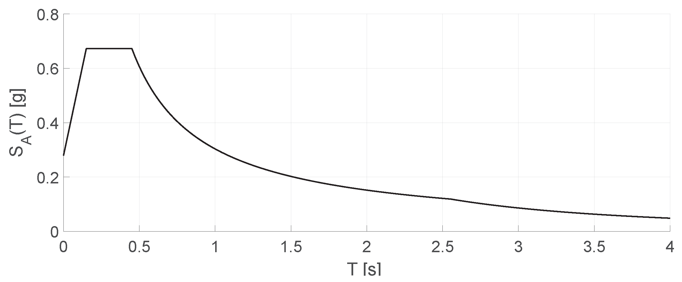
43], matching their spectrum with the site elastic response spectrum provided by the Italian Code for a
damping coefficient, which is shown in
Figure 5. The
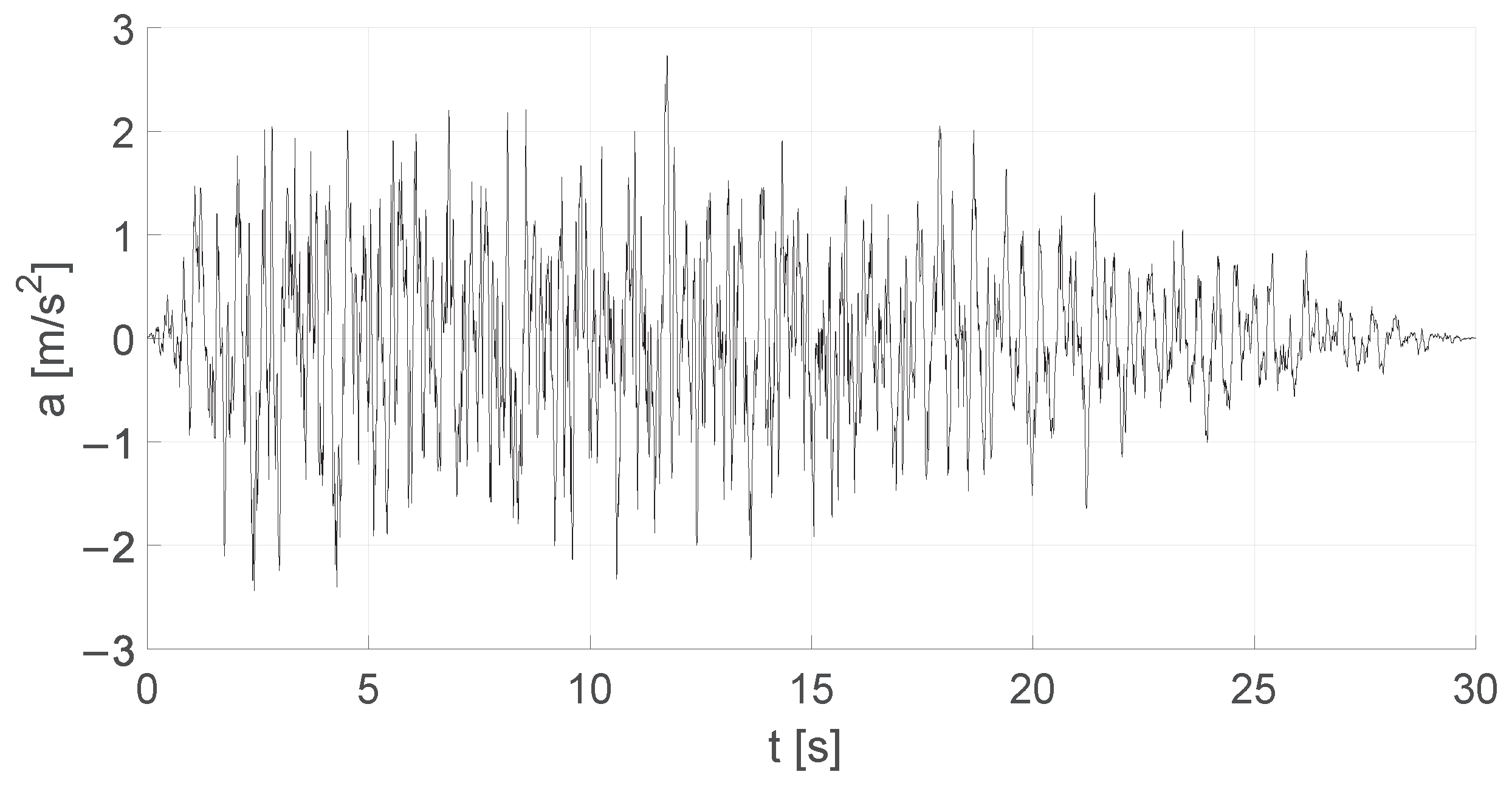
damping factor takes account of all phenomena related to the building shaking under horizontal loads contributing to energy dissipation in elastic conditions, such as concrete viscous properties and cracking. The accelerograms have a stationary part that starts at time
t = 2 s and lasts 10 s, for a total duration of 30 s. One of the horizontal accelerograms used in the analyses is shown in
Figure 6. The accelerometer record presented in
Figure 6 refers to the life-safety limit state according to the Italian Building Code [
41], hence with a
probability of occurrence in 50 years. The construction site of the building, Tolmezzo, is located in one of the areas of Italy with the highest seismicity. Therefore, the accelerogram shown is one of the most demanding for the Italian territory. For the structural members’ design, the most disadvantageous internal forces obtained from the three analyses are considered.
3. TMD Design Method
The mass of the TMD constituted a RC slab,
m long and
m wide, overlooking the entire rooftop and protruding by about 1 m from each façade, as shown in
Figure 7. The slab thickness was constant, and it was assumed as a design parameter of the TMD mass. A steel structure composed of braced frames oriented in the
X and
Y directions was installed on the rooftop to support the TMD above the stairwell and the elevator shaft, as shown in
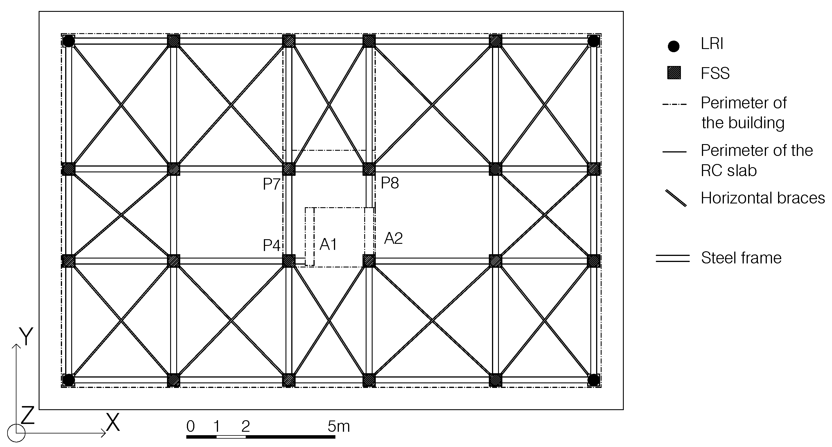
Figure 8. The RC slab lay on flat surface sliders (FSSs) anchored to the beam–column joints of the steel structure, which allowed the RC slab to sway out of phase with the building. The correct disposition of LRIs, LDRIs and VLDs in the two proposed solutions will be described in the design process in the next section.
In the steel structure, horizontal (
Figure 7) and vertical braces (
Figure 8) were used to provide in-plane stiffness to the plane at the base of the FSSs and horizontal stiffness to the steel frame, respectively. The steel structure’s self-weight is negligible in comparison with that of the building. Therefore, the increase in the building’s seismic mass due to this structure is also negligible. The design of the TMD was performed taking into account the availability of a new external living space at the level of the original roof and, consequently, the increase in gravity loads due to the variation in the roof’s intended use. In the FEM of the building, the steel structure was modeled through frame elements, while the RC slab was modeled through shell elements. For the FSS modeling, non-linear link elements of ‘Friction Isolator’ type were used.
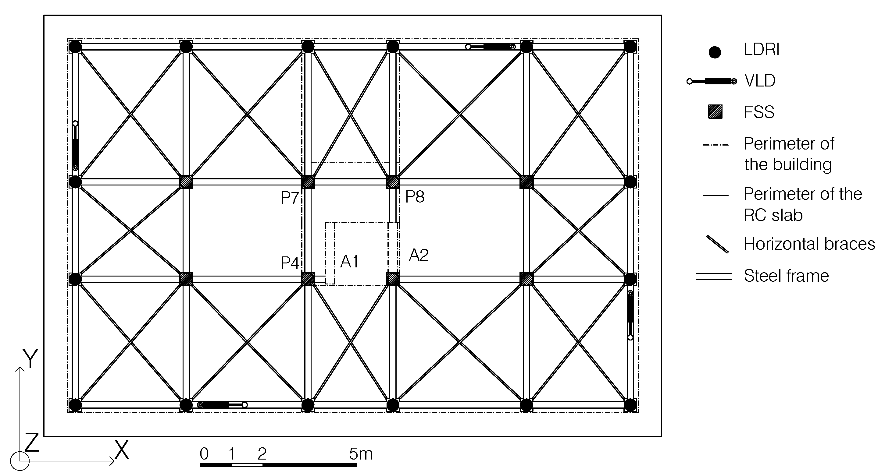
Since the horizontal stiffness and the energy dissipation contribution of the FSSs are negligible, to provide the TMD system with these properties, two solutions are proposed. In one solution (hereinafter referred to as TMD1), horizontal stiffness and damping are both provided by RIs, which are placed on the perimeter of the steel structure (
Figure 7). In the other solution (referred to as TMD2), horizontal stiffness is provided by LDRIs and damping by VLDs, which are installed along the perimeter of the steel structure, as can be seen in
Figure 7 and
Figure 8.
The construction of the TMD may follow these steps:
Installation of metal anchors to connect the base of the steel frame columns to the top end of the RC columns and walls of the building;
Assemblance of the steel frame with columns, beams and vertical and horizontal braces;
Installation of the FSSs, LRIs (in TMD1) and LDRIs (in TMD2) at the intersection nodes of beams, on the top of the steel frame, in the stairwell and in the elevator shaft, using steel plates to support them, if necessary. A way of access must be guaranteed for maintenance and to inspect and replace the isolation devices;
Positioning of the form and the steel reinforcement for the concrete slab on the top of the steel frame and pouring of the concrete. A slight slope for water collection is required;
In TMD2, VLDs can be installed after the curing of the concrete, connecting one end to a beam of the steel frame and the other to the under-surface of the RC slab, far enough away from the isolators to let them deform without making contact with the VLDs.
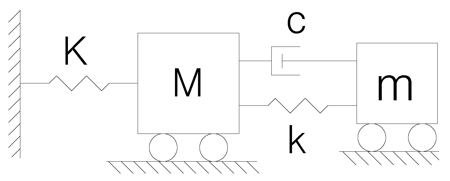
In both solutions, the design of the TMD is performed according to the analytical method described by Christopoulos in [
5]. In this method, the building structure is modeled through a single-degree-of-freedom (DOF) system of mass
M and stiffness
K, connected to the TMD mass,
m, by a linear elastic spring of stiffness
k and a linear viscous damper with viscous coefficient
c, disposed in parallel, as shown in
Figure 9. Therefore, the TMD behavior is completely described by the three parameters
m,
k and
c.
The dynamics of the two-DOF system in
Figure 9 when it is subjected to acceleration
at the base are described by Equations (
1) and (
2).
where
,
,
,
,
and
are the accelerations, velocities and displacements of OB and TMD, respectively, relative to the base.
The design method is based on the minimization of the building displacements caused by a random acceleration time history acting at its base. This criterion allows the limitation of the stress demand on structural members and the avoidance of damage to non-structural elements.
The design is carried out independently for motion along the X and Y directions. The TMD parameters obtained for each direction may be different due to the different properties (periods and participating mass ratios) of the main vibration modes along the main directions. The periods and the participating mass ratios of the main translational modes of the building considered in the case study are similar. Hence, the TMD parameters are calculated on the basis of the mode with the higher participating mass ratio. Otherwise, a TMD solution providing different stiffness and damping along the main directions of the building would have to be considered.
The determination of the TMD parameters m, k and c is divided into the following steps:
- 1
Definition of the mass ratio
between the TMD mass,
m, and the effective mass of the main vibration mode of the building without the TMD,
. In general, the choice of
m has to be made taking into account the bearing capacity of the structural members. In this case study, the structure can easily support, at ULS, an additional vertical load up to about
of the total mass of the building. In order to optimize the choice of
m, the design procedure proposed by Luft [
44] is used herein. In this procedure, the mass ratio is determined as
where
is the viscous damping factor of the i-th vibration mode of period
and the participating mass ratio
, and
is the damping factor of the acceleration and displacement spectra,
and
, respectively.
is determined so that the following inequalities are satisfied:
In (
4) and (
5),
and
are the target maximum acceleration and displacement at the top of the building, respectively, that can be borne without damage by the structural members. The values of
and
are determined by scaling the amplitude of the accelerograms.
- 2
Calculation of the frequency ratio,
f, between the frequencies of the TMD and of the structure with the following equation
and then the TMD stiffness,
k,
where
is the frequency of the i-th vibration mode of the building.
- 3
Calculation of the damping factor,
, and the viscous damping coefficient
c of the TMD with the following equations:
where
is the TMD’s natural frequency.
The values of k and are then used in the design of isolators and dampers.
After the definition of these parameters, the design of the TMD is completed by the implementation of the FEM of the building and the performance of its analysis. The choice of the model input parameters could be improved by means of on-site experimental dynamic tests on the existing building in order to obtain information about the building’s vibration modes. This information could be used to calibrate the FE model. In this way, the FEM-based approach to designing the TMD would better take into account the real behavior of the building. Another possibility to improve the design of the TMD is to realize a simple to-scale experimental dynamic test of a two-DOF system, such as the one in
Figure 9, where the two carts may be moved by a vibration table or an actuator, which can apply an accelerogram to their base. The mass
M should represent the building mass activated by the main vibration mode, and
K the corresponding stiffness. Different values should be chosen for the mass, the damping and the stiffness of the TMD to select the best combination that minimizes the force acting on the mass M. This force can be measured through a load cell.
In both cases, a direct-integration non-linear analysis should be conducted to assess the real behavior of the building with TMD.
3.1. TMD with RIs (TMD1)
In the first proposed solution, RIs are employed to provide the TMD with both stiffness and damping. The RI damping ratio, , usually ranges between and . The use of lead-rubber isolators (LRIs) can be considered when a higher damping coefficient is required, up to .
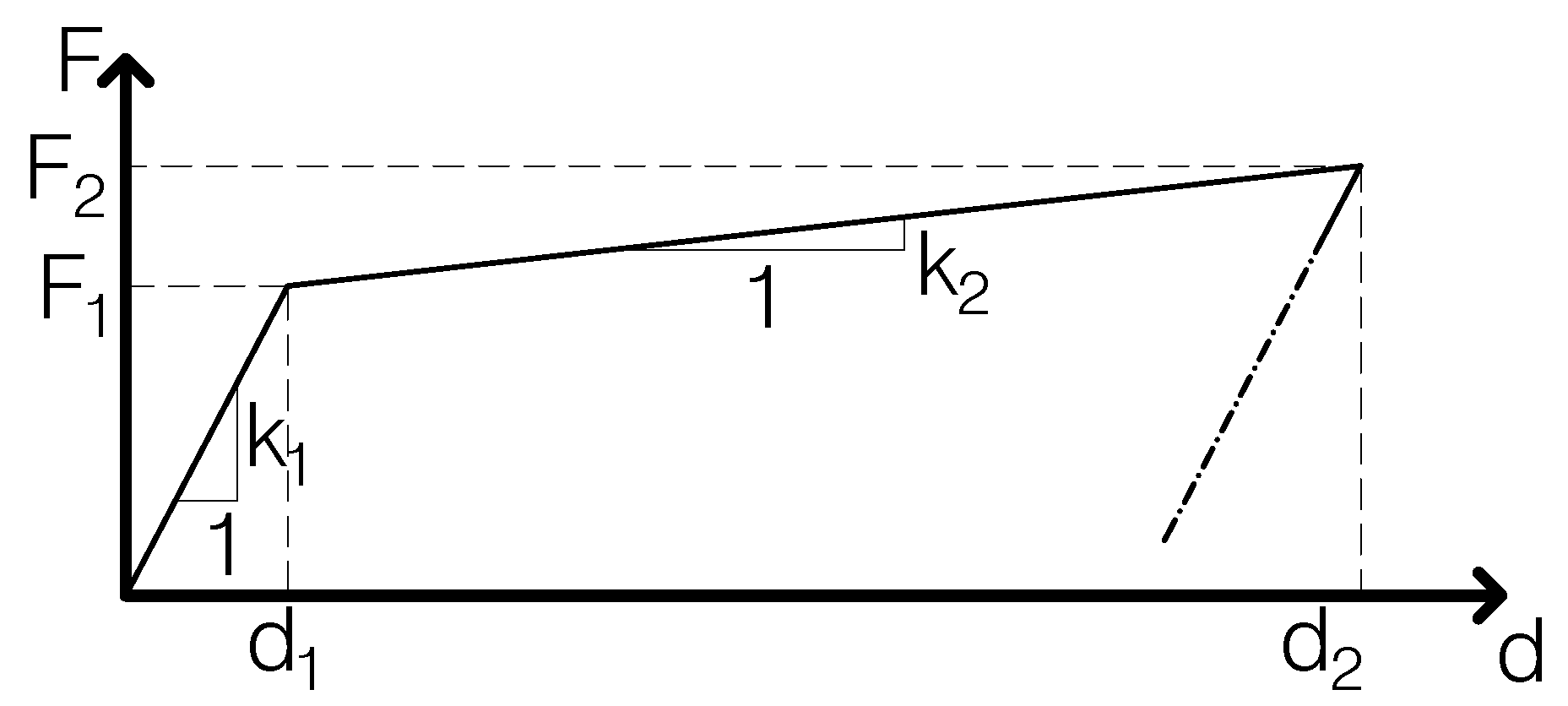
To implement RIs in the FEM of the building, the non-linear link element called ‘Rubber Isolator’ is used. This element has a bilinear force–displacement (F-d) relationship, like the one shown in
Figure 10. The first branch of the diagram, of slope
, describes the isolator behavior up to the yielding point of coordinates
, while the second branch, with slope
, describes the post-yielding behavior up to the maximum force
and the maximum displacement
.
is the secant stiffness corresponding to the displacement that the RI undergoes.
The isolators’ design consists of choosing the number of devices and of determining their stiffness
and equivalent damping factor
through the design method described above. In particular,
is obtained by dividing the value of
k obtained from Equation (
7) by the number of isolators, and
coincides with the value of
calculated with Equation (
8). Then, the values of
,
and
are computed with the formulas provided by FEMA [
45].
3.2. TMD with LDRIs and VLDs (TMD2)
In addition to the FSSs, the second solution employs LDRIs and VLDs to provide the TMD with horizontal stiffness and damping, respectively.
LDRIs are composed of layers of natural rubber (without the usual additives, such as carbon black) alternating with steel shims. Since they have a damping factor of about
, in the FEM of the building, LDRIs are modeled through linear elastic springs of stiffness
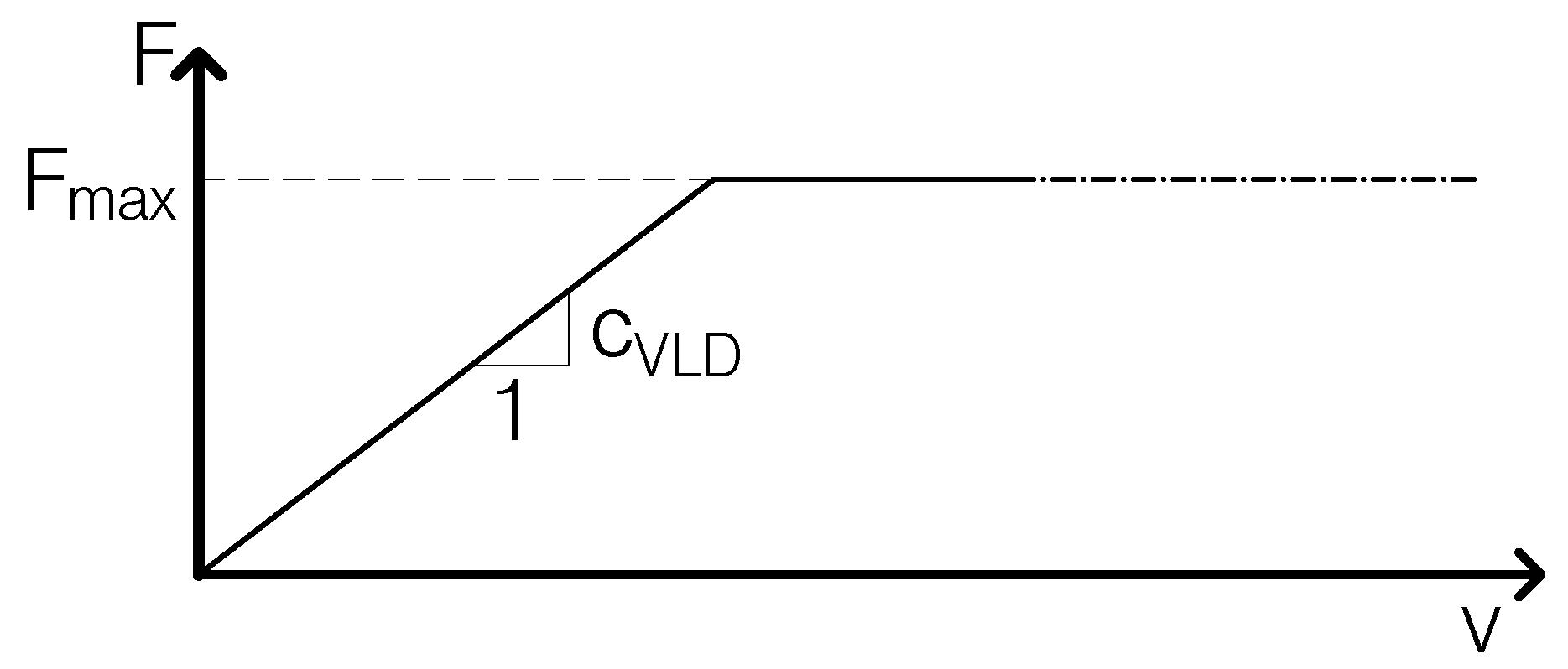
. Conversely, the non-linear behavior of VLDs is modeled in SAP2000 through the non-linear link ‘Damper - Bilinear’, in which a linear elastic spring of stiffness
and a dashpot are connected in series. The force in the dashpot is directly proportional to the relative velocity
v of its ends through a damping coefficient
up to the maximum force
, as shown in
Figure 11. The values of
and
are provided by the manufacturers of the device.
The value of
is calculated by dividing
k (from Equation (
7)) by the number of LDRIs, while the value of
is calculated dividing
c (from Equation (
9)) by the number of VLDs.
4. Results
The design of the TMD is performed with the aim of changing the building’s structural behavior under SLV sesimic actions from dissipative to non-dissipative. This aim is set to avoid damages to structural and non-structural elements at the SLV in order to eliminate costs for the building’s reparation. In regards to structural elements, damage is considered as the exceeding of the elements’ yield strength.
It is also fundamental to avoid TMD detuning. Actually, plasticization of structural members induces a modification of the building stiffness and vibrational modes, thus changing the building properties considered in the design process. According to [
41], the structure’s behavior is non-dissipative if its members work in the so-called ‘substantially elastic field’.
The internal forces in the isolated structure are divided by a factor of
, as allowed by the Italian Code [
41] and the Eurocode [
46]. For all vertical structural members, strength verifications are carried out at the base (
m), at the top of the building (
m) and at the level where the walls’ longitudinal reinforcements are reduced (
m).
The properties of TMD1 and TMD2 derived from the design process are presented. The effects of TMD1 and TMD2 on the building’s modal behavior, strength verifications and energy dissipation are also provided. Results obtained for the building with TMD1 and TMD2 are compared with those of the OB and with those of the building seismically protected by a base isolation system (BIS).
4.1. Properties of TMD1 and TMD2
As discussed in
Section 3, the TMD design is based on the main vibration modes of the building. Since the installation of the TMD on the building’s rooftop requires the steel frame structure described in
Section 3, the vibration modes to consider are those of the OB with the steel structure on the top (OBS).
Table 4 shows the periods and the participating mass ratios of the most significant modes of the OBS.
From
Table 4, it can be seen that the first two modes are translational in the
X and
Y directions, respectively, and the third is rotational. These three modes have similar periods, ranging between 0.35 s and 0.41 s, and very similar participating mass ratios in the main direction, varying between
and
. The remaining modes have lower periods, ranging between 0.08 s and 0.09 s. The modes of the OBS are practically identical to those of the OB (
Table 3).
The design method requires that the values of and be fixed. In order to maintain the structural members in the elastic field and to avoid damage to masonry infill panels under the seismic actions at the SLV, the values m/s and m were taken. These values lead to a mass ratio equal to . As the effective mass of mode 2, equal to , an RC slab thickness of equal to m is derived. If the TMD design was made taking different values of and in the X and Y directions, the values of and to take in the X direction would be m/s and m, respectively, which would lead to . Consequently, with , a thickness of the RC slab equal to m would be obtained.
From the values of k and , the number and characteristics of LRIs, for TMD1, and those of LDRIs and VLDs, for TMD2, can be determined. Then, the strength verifications of structural members are made, and the maximum values of the flexural demand over capacity ratio equal to for TMD1 and equal to for TMD2 are found.
However, the values obtained for
and
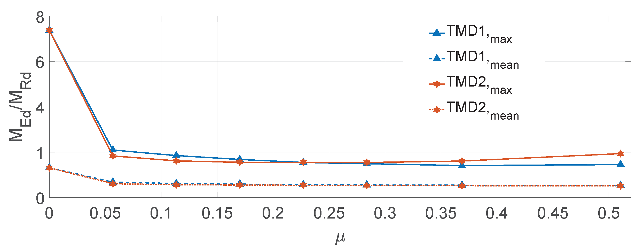
are considered to be too large. Therefore, the performance of smaller TMDs is investigated. The trend of
obtained for TMD1 and TMD2 as
varies between 0 (OB) and
is shown in
Figure 12.
In this figure, the mean values of the flexural demand over capacity ratios obtained for the two proposed solutions are also shown. From
Figure 12, it can be seen that, in both solutions,
decreases monotonically as
increases, passing from
for the OB to
for TMD1 and
for TMD2, but the decrease is negligible from
. Moreover, from
Figure 12, it can be observed that the designed TMDs do not lead to the minimum values of
as the minimum values are achieved with lower values of
, and in particular with
for TMD1 and
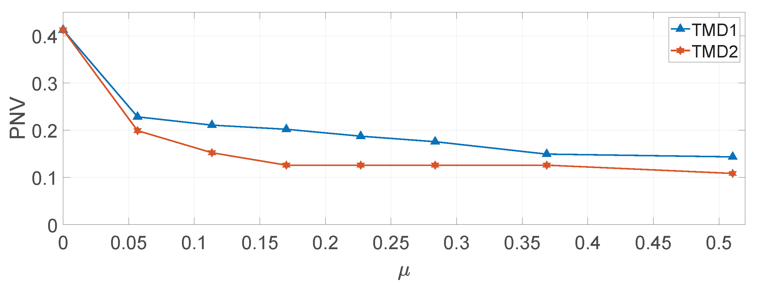
for TMD2. Therefore, a greater mass of the TMD does not mean better performance. Hence, the optimum thickness is defined on the basis of the percentage of not-satisfied verifications (PNV) of the structural members. The trend of PNV as a function of
obtained for the two solutions is shown in
Figure 13.
From
Figure 12 and
Figure 13, it can be observed that for both TMD solutions
is already sufficient to largely reduce the flexural demand to structural members and the PNV. Mass ratios larger than
provide only a slight further reduction in the flexural demand and the PNV. In particular, both solutions provide the best results for
, but, also taking into account the
trend, the values
for TMD1 and
for TMD2 are considered optimal.
These values of
are obtained from the values of
reported in column (1) of
Table 5 and
Table 6 for TMD1 and TMD, respectively. The parameters of the TMD calculated with Equations (
6)–(
9) are reported in column (2) of
Table 5 for TMD1 and
Table 6 for TMD2. Then, the properties of LRIs for TMD1 (in column (3) of
Table 5) and those of VLDs and LDRIs for TMD2 (in columns (3) and (4) of
Table 6, respectively) are determined.
The position of LRIs and that of VLDs and LDRIs in the building plan are shown in
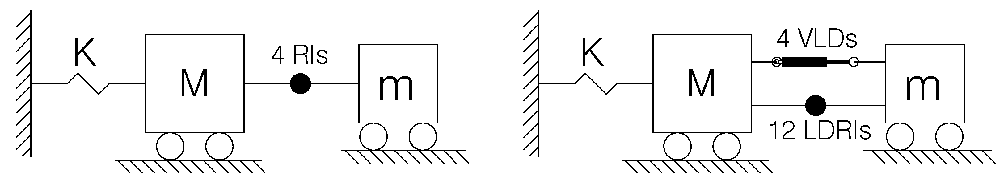
Figure 14 and
Figure 15, respectively. The schematization of the simplified two-DOF structure-TMD systems are shown in
Figure 16.
TMD1 makes use of four LRIs placed at the corners of the steel structure, as shown in
Figure 14, in order to maximize the TMD’s torsional stiffness.
In TMD2, due to the low shear modulus of LDRIs, which is equal to 0.45 MPa, to provide the TMD with the design stiffness, 16 devices are required (
Figure 15). Two VLDs in each main direction of the building are placed on the steel frame perimeter symmetrically with respect to the main axes of the building plan (
Figure 15).
4.2. Design of the Base Isolation System (BIS)
In addition to the seismic protection strategy based on the use of TMD, the strategy based on building seismic isolation is also considered. BIS is designed to increase the fundamental period
of the building up to the value
such that the corresponding spectral acceleration at the SLV,
, is equal to or lower than the spectral acceleration,
, divided by the maximum value of
. For the OB,
is equal to
. The stiffness of the BIS,
, is then determined from the total mass of the building,
M, which is equal to
. For the considered case study,
m/s
, which is attained for
s. Consequently,
kN/m is obtained. To provide the BIS with this stiffness, eight RIs with the properties shown in
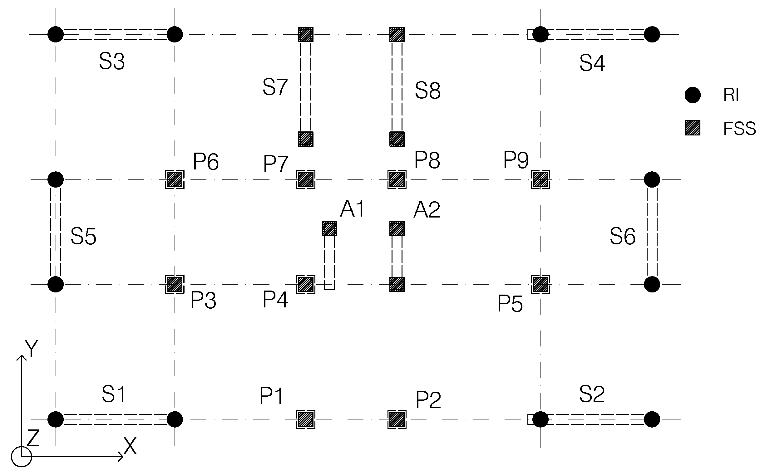
Table 7 are used. The RIs are placed at the base of the walls lying on the building perimeter. At the base of the remaining structural elements, FSSs are installed. The layout of RIs and FSSs in the building plan is shown in
Figure 17.
4.3. Vibration Modes of the Building after the Interventions
The modal information of the building equipped with TMD1 is shown in
Table 8.
From this table, it can be seen that the modes can be subdivided into three groups, each constituted by three modes: the first two translational in the
X and
Y directions, respectively, and the third rotational. The first group, composed of modes 1 to 3, is characterized by higher periods than those of OBS (
Table 4), ranging from 0.62 s (mode 1) to 0.47 s (mode 3). The participating mass ratios of these modes range between
and
. The second group of modes, composed of modes 4, 5 and 6, is characterized by periods that are slightly lower than those of modes 1, 2 and 3 of the OBS and mass participating ratios that are about half, ranging between
(mode 6) and
(mode 4). The periods and mass participating ratios of the last group of modes (modes 7–9) are similar to those of modes 4–6 of the OBS. These modes are fundamentally those of the OBS, since the TMD does not participate in them.
Similarly to what was performed for the building equipped with TMD1, the modal properties of the building equipped with TMD2 are shown in
Table 9.
From the comparison with
Table 8, it can be observed that the effect of TMD2 on the vibration modes of the building is very similar to that of TMD1, since the periods and participating mass ratios of translational modes are almost identical. A slight difference emerges in rotational modes 3 and 6, whose participating mass ratios are, respectively, higher and lower than those of TMD1.
The modal information of the original building with the BIS is shown in
Table 10.
It can be seen that the dynamic behavior of the building is fully described by only three modes, which altogether provide participating mass ratios of
for each DOF of the building. The periods of the translational modes, equal to 2.87 s for modes 1 and 2, fall in the last branch of the acceleration site spectrum in
Figure 5.
From the comparison of the modal analysis results of the OB (
Table 4) with those of the building equipped with TMD1 (
Table 8), TMD2 (
Table 9) and BIS (
Table 10), it can be noticed that all three interventions produce significant modifications of the building modes.
4.4. Strength Verifications
The flexural demand over the capacity ratios for the OB and the building equipped with TMD1, TMD2 and BIS and their percentage variation from those of the OB are shown in
Table 11 and
Table 12, respectively, for walls and columns.
Shear demand on structural members is always lower than their current capacity for the OB, and it is reduced in the building with TMD1, TMD2 and BIS. In particular, the shear demand at the base of the vertical members is reduced by at least for the building equipped with TMD and for the base-isolated building. Axial forces are also reduced by at least and , respectively.
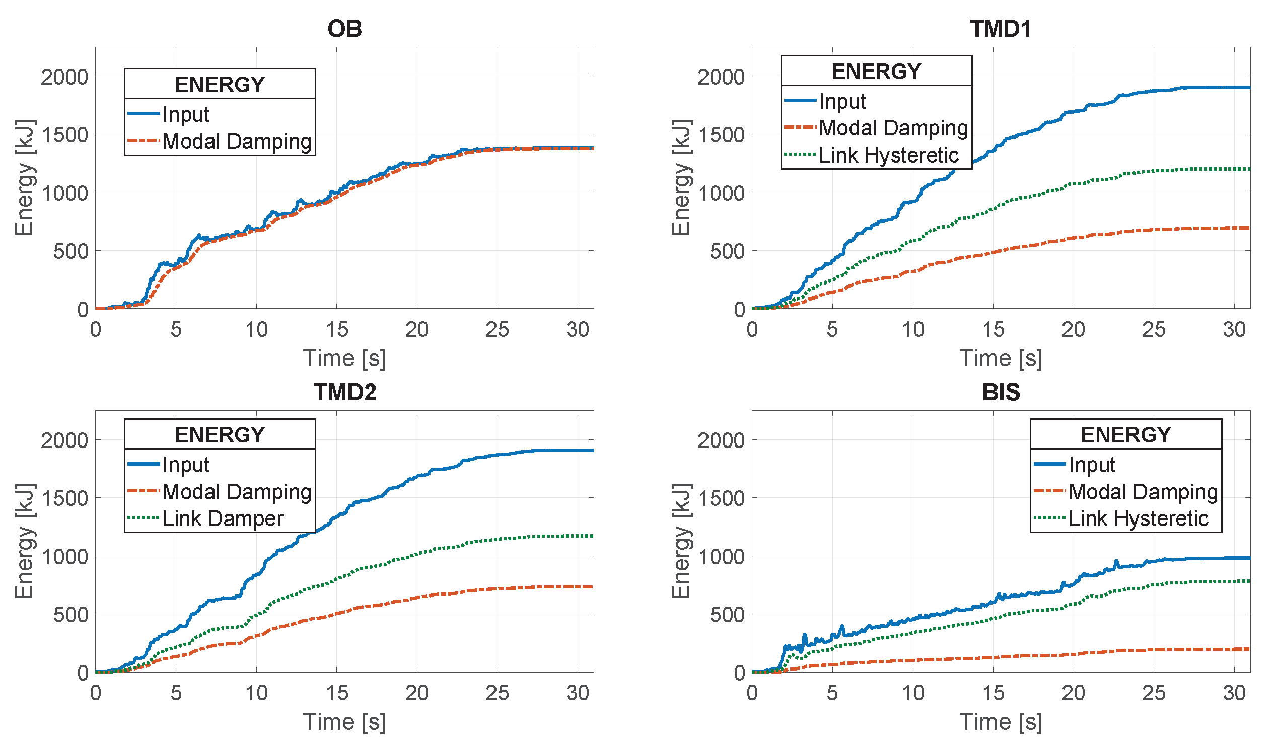
4.5. Input and Dissipated Energies
The graphs of cumulative input and dissipated energies of the OB and of the building with TMD1, TMD2 and BIS obtained from one of the three non-linear analysis cases are shown in
Figure 18.
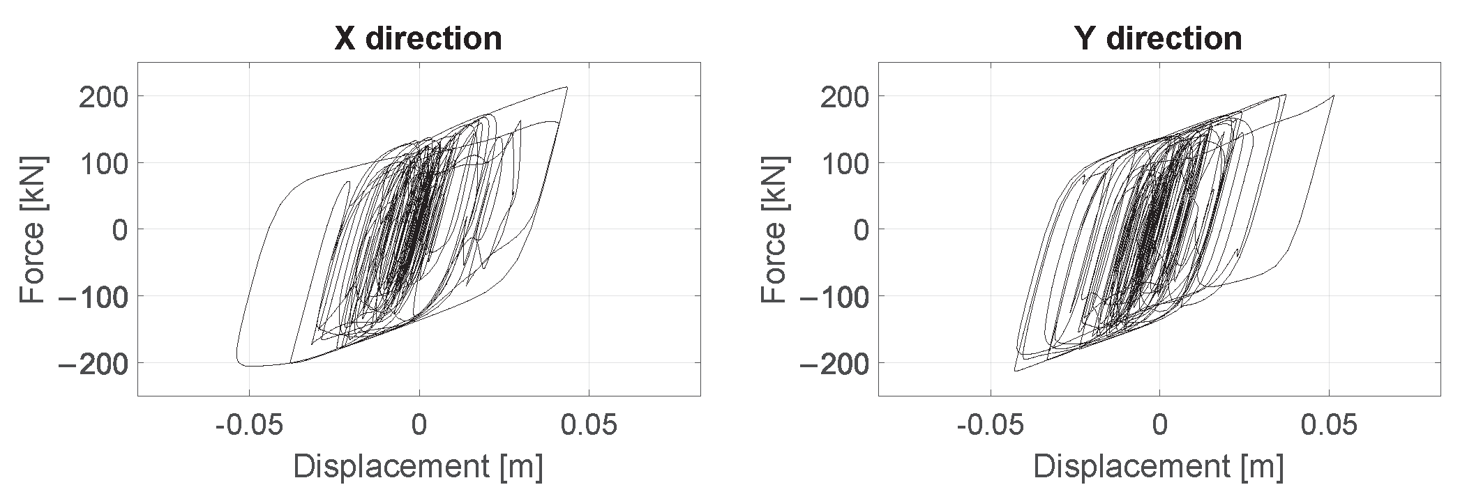
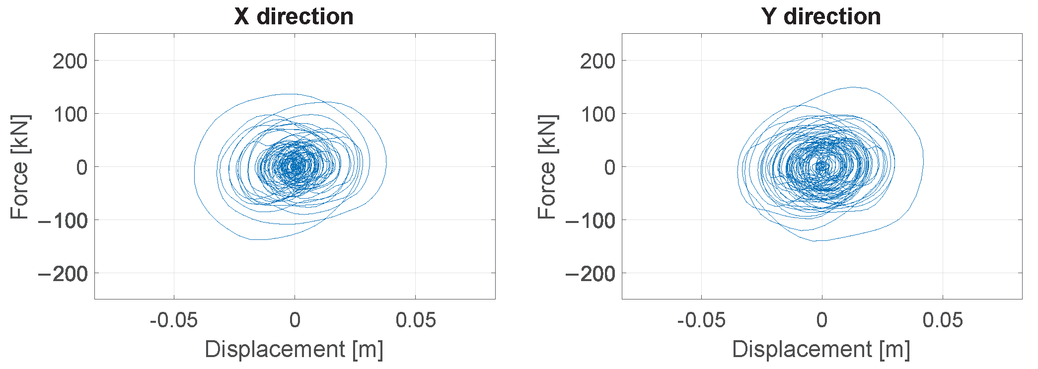
The force–displacement diagrams in the
X and
Y directions of one LRI (TMD1) and one VLD (TMD2) are shown in
Figure 19 and
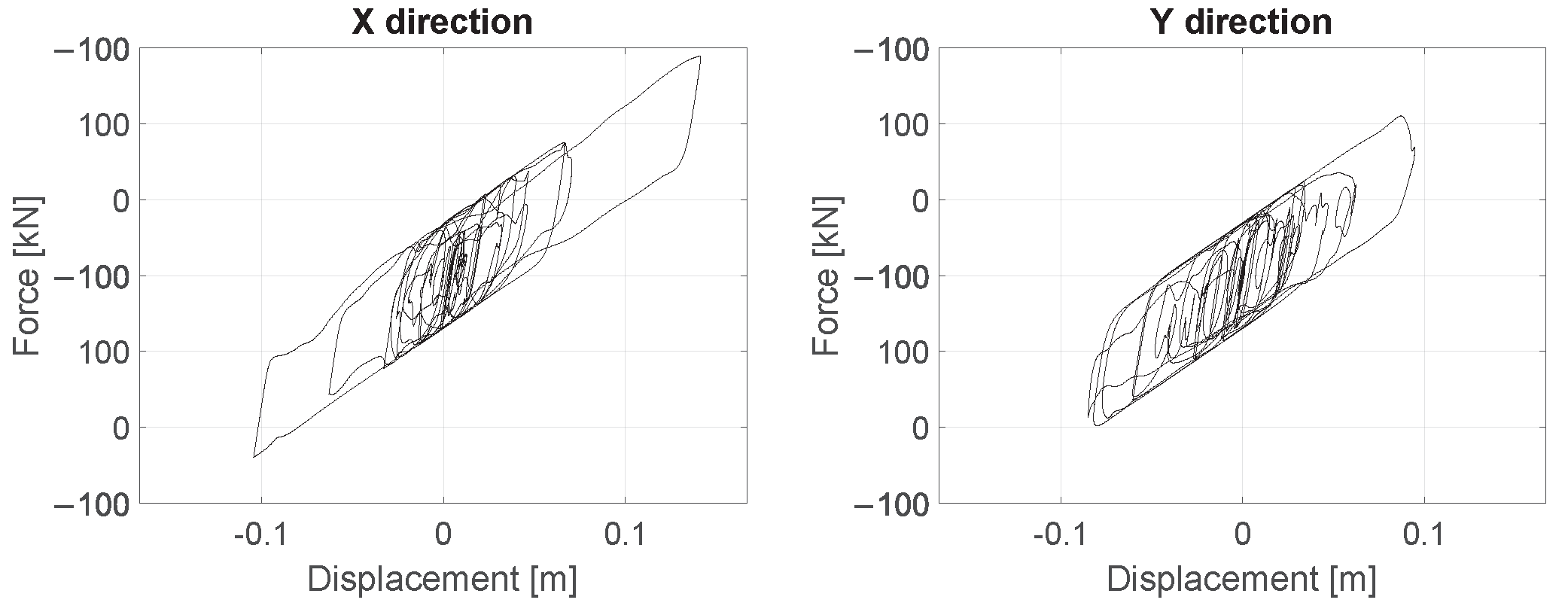
Figure 20, respectively. Similarly, the force–displacement diagrams in the
X and
Y directions of one RI of the base-isolated building are shown in
Figure 21.
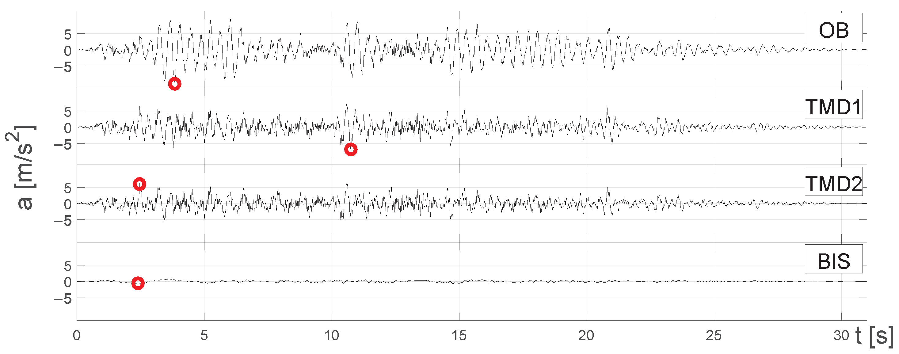
4.6. Maximum Accelerations
In
Figure 22, the roof barycenter acceleration along the
X direction of the OB and of the building with TMD1, TMD2 and BIS versus time graphs is shown. The peaks of maximum acceleration in each graph are highlighted with a red circle. The maximum amplitude of acceleration on the OB equals
m/s
, and it can be observed that the installation of TMD1 and TMD2 reduces its value to
m/s
and
m/s
, respectively, while the base isolation system binds it below
m/s
.
6. Conclusions
In this study, a tuned mass damper (TMD) was designed to be installed on the rooftop of a medium-rise building in order to change the building’s behavior from dissipative to non-dissipative under seismic action. The application of the TMD was aimed at reducing stresses in structural members and floor displacement in order to avoid damage to structural and non-structural elements under strong earthquakes. Thereby, the building with TMD would not need reparation interventions after such earthquakes.
In the proposed solution, the mass of the TMD is made by an RC slab laying on flat surface sliders (FSSs) installed on the building rooftop. Two different solutions were proposed to provide the TMD with design stiffness and damping. In one solution (TMD1), stiffness and damping are both provided by lead rubber isolators (LRIs), while in the other solution (TMD2), stiffness and damping are provided by low-damping rubber isolators (LDRIs) and viscous linear dampers (VLDs), respectively.
Starting from the TMD mass value obtained from the adopted design method, the optimal masses of TMD1 and TMD2 were and of the total mass of the building, respectively.
The proposed solutions led to very similar results. It was observed that the TMD significantly changes the main vibrational modes of the building, reducing the spectral accelerations. Consequently, a reduction in flexural and shear actions of at least at the base of the walls and of at least at the base of the columns was achieved. The flexural demand over capacity ratios were strongly reduced, bringing the maximum from (OB) to and with TMD1 and TMD2, respectively. Based on this result, it can be concluded that the designed TMDs are effective in reducing the stresses in the structural elements of the considered medium-rise building, almost to the substantially elastic bound. Both TMDs involve an increase in the input energy, but most of it is dissipated through damping by TMD devices, hence halving the energy dissipated through modal damping by the building.
A base isolation system (BIS) was also designed to compare its effectiveness in reducing the stresses in the building’s structural members with that of TMD1 and TMD2. BIS proved to be the most effective strategy, as expected, since it radically increased the periods of the building’s vibration modes. This produces a reduction in the shear actions at the base of the building of at least , leading the strength verifications of structural members to all be largely satisfied.
However, from the results obtained for the case study, it can be concluded that a TMD can be used for the retrofit of existing buildings as a valid alternative to base isolation when the latter is technically unfeasible.


