Article

Considerations for the Design of a Wheelchair Dynamometer Concerning a Dedicated Braking System

1
Faculty of Mechanical Engineering, Institute of Machine Design, Poznan University of Technology, 60-965 Poznań, Poland
2
Faculty of Mechanical Engineering, Institute of Mechanical Technology, Poznan University of Technology, 60-965 Poznań, Poland
*
Author to whom correspondence should be addressed.
Appl. Sci. 2023, 13(13), 7447; https://doi.org/10.3390/app13137447
Submission received: 18 May 2023 / Revised: 21 June 2023 / Accepted: 22 June 2023 / Published: 23 June 2023
(This article belongs to the Special Issue Hysteresis in Engineering Systems)

Abstract

:
As part of ongoing research, a wheelchair dynamometer has been designed and built. This device is a complex test stand, enabling research on the operation of wheelchairs, taking into account a number of biomechanical factors in laboratory conditions. Based on a review of the available literature, the braking system was designed and constructed as a part of a dynamometer drive system. This has resulted in a design issue concerning the optimal selection of the electromechanical drive combined with a hydraulic system as the actuator of the brake. The purpose of the research discussed here is to determine the characteristics of the braking system. For this purpose, a series of tests were carried out using a wheelchair with an electric drive, which allowed the generation of a constant rotational speed in the range between 72 rpm and 222 rpm. Based on the test results, the hysteresis of the developed braking system and the characteristics of the braking power were determined.

1. Introduction

Brakes are integral to drive units. Their purpose is to dissipate energy, either for the purpose of speed control or in order to bring the system to a complete standstill. There are many types of brakes that may be classified in terms of the forces generated in them. Brake force (or torque) may be generated through the action of the forces of a magnetic field, the resistance of a medium (either liquid or gas) or friction. Different solutions have different functional properties and thereby have unique advantages and disadvantages. For this reason, it is necessary to choose the correct type and size of braking system for specific applications. The issue presented here is related to R&D work that focused on building a test stand for wheelchairs. This unique application requires a dedicated drive unit. Its braking system is especially important because it must meet a series of requirements arising from its operating conditions. Its function is crucially the need to generate a constant and adjustable braking torque value at a low rotation speed. Other important requirements also have to be met, such as the simplicity of control and minimal impact on the components of the measurement system. The motivation to undertake development work in this area was the requirement of a test stand with a wheelchair dynamometer. The purpose of the stand in question is to enable the measurement of biomechanical parameters related to wheelchair mobility and propulsion biomechanics. This will enable the analysis and comparison of the efficiency of the propelling mechanism of wheelchairs with regard to design, construction and various drive systems. This test stand will also enable the modeling of the kinematics of the propulsion process. It will enable the measurement of a number of parameters related to movement, such as the position of the center of gravity, the demand for drive torque or motion capture measurements, depending on various conditions of movement. The test scenario may include driving at different velocities and driving uphill, but also movement with adjustable resistance, for which a dedicated braking system is required. The developed measurement system also enables the measurement of the drive torque on the wheels of the wheelchair. This is quite important because the measurement of this value in the case of a wheelchair is difficult to implement technically.
The preliminary work involved an analysis of a number of technical ways to generate braking torque. The drive unit’s requirements in terms of the power transmitted and the nature of the device’s operation led us to decide that the best way would be to use a mechanical friction brake (a disc brake). In particular, a servomechanism that used a BLDC motor to generate the load torque was considered. The task of this system would be to generate and hold a constant torque value independent of the rotational speed (for a certain range of rotational speed values). Additional resistance in the system that must be overcome in order to propel the wheelchair would effectively constitute the braking of the wheels. A system operating on this principle was used in an earlier version of the wheelchair dynamometer. The description and principle of its operation are found in [1,2]. A decision was made, however, to implement the braking system differently. Generating a constant value of resistive torque (for a selected range of rotational speeds) using a servomechanism with an electric motor is both unnecessary and complicated from a technical point of view.
A typical drawback of this design is disc brakes’ tendency to generate great amounts of heat, and this requires the dissipation of this heat [3]. This heat generation arises from the brake pad’s friction against the brake disc, a phenomenon that takes place over a relatively small contact area compared, for example, to a drum brake. Due to the small diameter on which the brake actuating force is applied, the force also requires a significant value in order to enable the generation of high braking torque, so hydraulic systems are often used for this purpose. Disc brakes have a number of evident advantages, such as especially good performance parameters.
Systems that utilize frictional force for this purpose involve problems that arise from the velocity-dependent friction attendant on the interoperation of steel brake discs and brake friction composites used on friction components. This is an important property from a tribological viewpoint because it is used to assess the braking system’s propensity for generating noise [4]. The slope of the curve graph for the dependency between the friction coefficient and speed is an important value. This parameter is used in the assessment of friction instability in braking systems since a decrease in friction with a simultaneous increase in speed causes vibration and noise in braking systems [5,6,7].
While the cause of the velocity-weakening friction in brake friction composites is a complicated issue, related experimental testing is limited [4]. This is due to the great diversity in the materials used in the manufacturing of commercial brake composites, resulting in the creation of complicated sliding surfaces [8].
Another drawback of disc brakes is their rigidity. Disc materials, especially pad materials, have a certain elasticity. The caliper and its mounting are also characterized by a certain degree of flexibility. The so-called stick-slip phenomenon may consequently arise at low rotational speeds [7]. This is a result of the susceptibility of the above-mentioned components that couple with motion through frictional force. This may give rise to instabilities in the braking system [9].
The possible occurrence of hysteresis losses is also important in the context of friction brakes. This is explained by a change in the brake’s frictional force when the brake is released. In paper [10], the authors tested hydraulic brake components in a light commercial truck. They were able to determine the impact of individual components, including the disc brake mechanism, on the hysteresis losses. An analysis of the current state of knowledge leads us to conclude that the occurrence of this phenomenon affects both the operation of brake calipers and valves [11,12,13] as well as the operation of disc brakes [14,15], especially in heavy vehicles. The response rate of anti-lock braking systems [16,17,18] may also depend on the occurrence of hysteresis losses. Research is currently being carried out with the aim of modeling a braking system’s operation in dynamic conditions for the purpose of optimizing its parameters and the control algorithm [19,20].
The objective of the work described in this paper was to design, construct and determine the characteristics of a dedicated braking system. A design was formulated, and a prototype was subsequently constructed and tested for this purpose. Following an analysis of the available solution, the decision was taken to use a friction disc brake. This choice was a result of the system’s specificity, which required the generation of the set braking torque at a low rotational speed. In such conditions, friction brakes are characterized by stable operation, which, in combination with their simple design and control, is crucial.

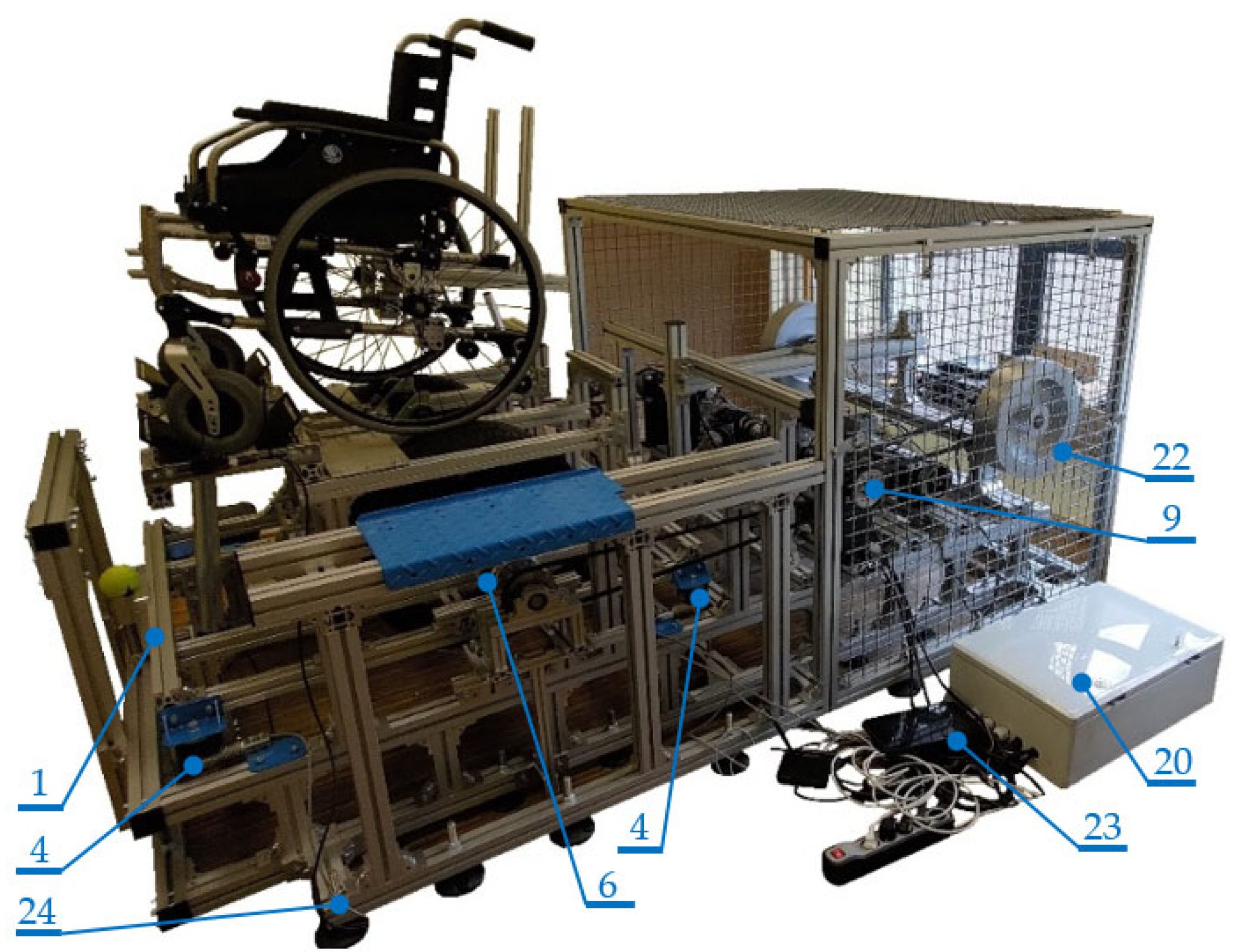
2. Materials and Methods

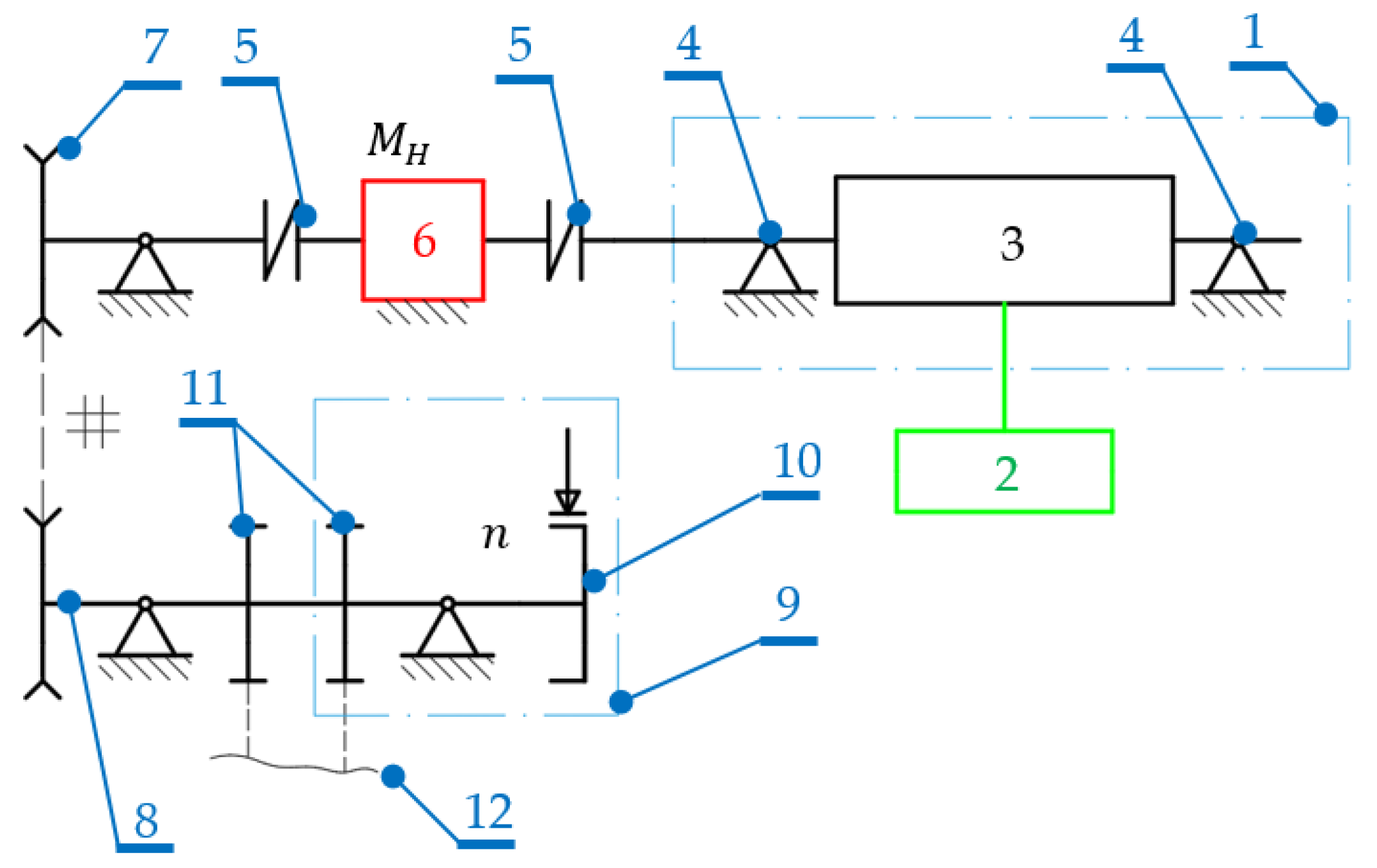
2.1. Measurement Methodology

The issue here addresses research and development work that focuses on building a test stand for wheelchairs. It is a complex test stand constructed in accordance with [21] and enables the measurement of a number of biomechanical parameters related to the propulsion of a manual wheelchair. The system’s design schematics are presented in Figure 1. Its operating principle relies on the frictional interoperation between the wheelchair’s wheels (2) and rollers (3) as part of a roller system (1). The rollers (3) are mounted on bearing shafts (4) that interoperate via flexible couplings (5) with a torque gauge (6). It transfers the torque M ( t ) and rotational speed n ( t ) via the chain transmission (7) to the main shaft (8). The main shaft (8) features other mechanical transmissions (11) intended for various simulation and measurement functions, the purpose of which exceeds the framework of this elaboration. The main shaft (8) interoperates with the brake assembly (9), which is equipped with a brake (10), the purpose of which is to generate the resistance torque M ( t ) . The value of the drive torque that a wheelchair user must generate depends on the resistance of the dynamometer’s mechanical system. The value of this resistance depends to some extent on the efficiency of its components, but mainly on the settings of the designed braking system. It is therefore possible to load the wheelchair’s wheels with an adjustable value of the braking torque. This enables a simulation of various types of measurement scenarios with simultaneous measurement of motion parameters.
A view of the wheelchair dynamometer is given in Figure 2. The dynamometer consists of a number of systems and modules that are responsible for simulating real movement conditions and scenarios while simultaneously measuring biomechanical parameters. The device consists of the main frame (24) that supports the roller system (1), the brake assembly (9), the rotating mass module (22) and the torque gauge (6). The device also has a number of covers, whose task is to ensure the safety of use and service by physically separating the moving elements from the environment. The structure of the dynamometer system developed in this way combined with the designed measuring system makes it possible to determine the position of the user and the wheelchair’s center of gravity. It is also possible to measure the parameters of the generation of propulsion parameters, such as drive torque and rotational speed. This study analyzed the operation of the brake module (9) and its characteristics. The location of the center of gravity affects the stability of the system [22]. As the location of the individual elements of the wheelchair affects these parameters, it is important to arrange the position of the equipment (wheels, seat, brakes, armrests, etc.) properly on the frame [23].

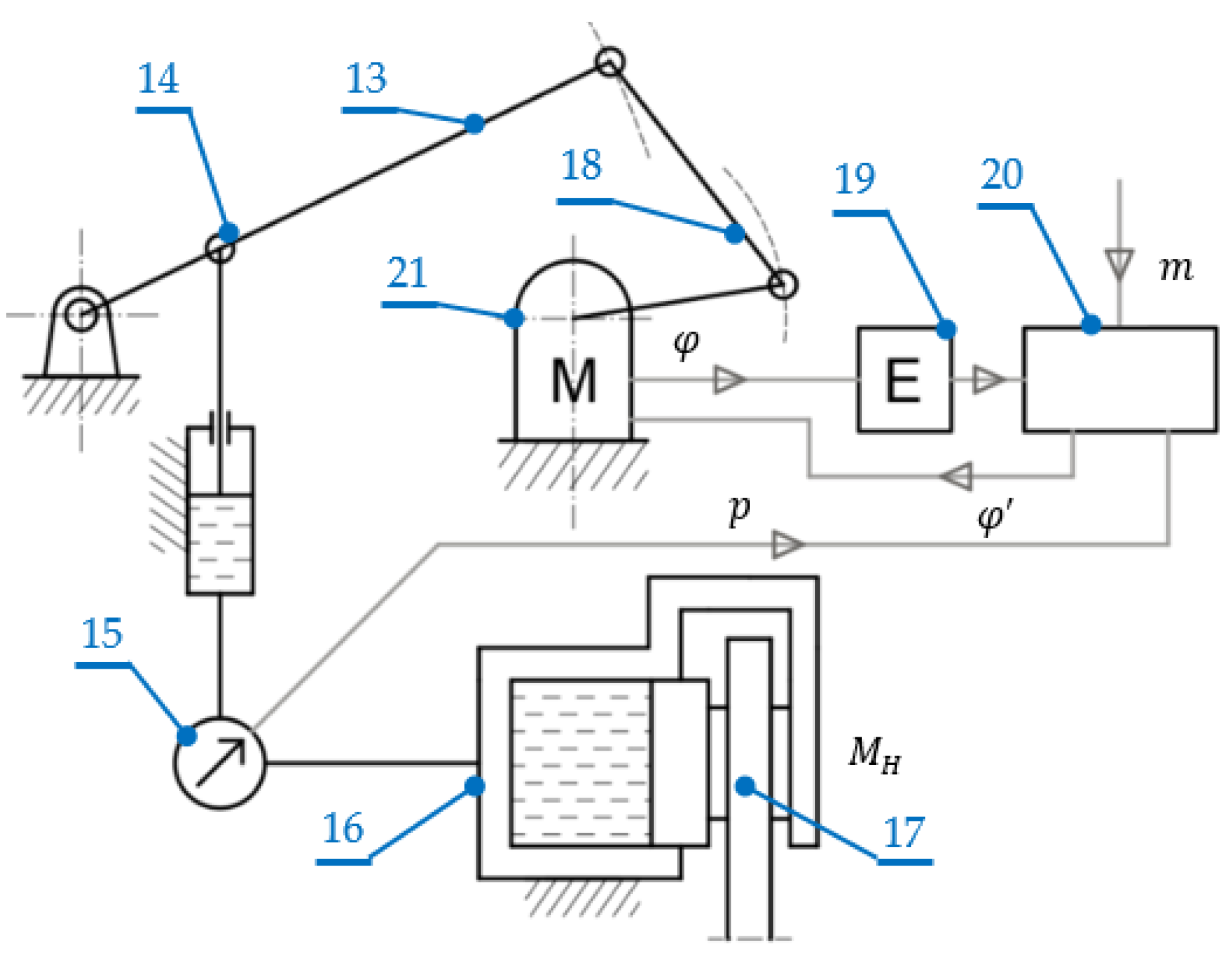
2.2. Selection of the Electric Drive and the Control System Design

The essence of the designed braking system was to enable the control of friction braking force settings in a continuous and repeatable manner. Classic mechanical and mechanical–hydraulic systems, despite a wide range of applications in technology and great efficiency, were not used in this case due to their inability to meet the above requirements regarding control. In order to meet the set requirements, the structure created is therefore an electromechanical disc brake control system (EMB) with a hydraulic system generating brake pad pressure. In contrast to traditional braking systems, the use of an electro-mechanism allows an increase in the efficiency of the brake and precise control of the braking force settings, as well as relatively easy control via the integrated electronic panel [24,25]. Based on the review of the literature, three types of estimation of the brake pad pressure force are distinguishable. These are methods based on the angular displacement of the electric motor, its current or a hybrid combination of the two [24]. We decided to implement system control via the angular displacement of the motor, which is an efficient method for the structure created.
The schematics of the described method’s control system are presented in Figure 3. The main component is the brake lever (13), the movement of which shifts the hydraulic piston (14). As a result, the brake piston (16) is shifted, which in turn causes the shoe to clamp onto the brake disc (17). The shift in the brake lever (13) is caused by the rotation of the electric engine (21) via the connector (18). The electric engine (21) is controlled by the control system (20). The control system (20) is supplied with pressure p from the liquid from the pressure sensor (15), which is installed between the hydraulic piston (14) and the brake piston (16). The system utilizes an electric engine consisting of a TSP-202005 servomechanism (TSP-Racing, provided by Conrad LLC, Poland), which was selected based on the brake lever clamping force demand calculations. The electric engine (21) is equipped with an encoder (19) that measures the current angular position φ and simultaneously transmits this value to the control system (20). This constitutes the basis for the generation and correction of the set position φ of the electric engine (21). As a result, the brake shoe clamp set on the controller (20) (setting m ) is converted to the engine’s angular displacement φ , which is adjusted using a feedback loop based on the engine’s actual angular displacement φ and pressure p in the supply line of the brake piston (16). The key issue in the system is the designation of the dependency between the braking torque M H and the setting m , i.e., the function M H = f m .

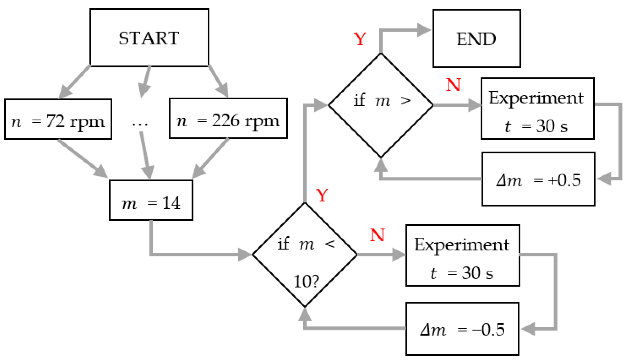
2.3. Measurement Methodology

An electric drive wheelchair was placed on the test stand to enable measurements. This enabled the generation of drive with the set rotational speed. Figure 4 presents the measurement scheme in the form of a block diagram for the sake of clarity. Measurements were conducted for five different rotational speeds ( n = 72, 109, 148, 184 and 226 rpm). The m parameter values correspond to the degree of brake release and may be defined in the control programme as a variable. A value of m = 14 indicates that the brake is fully released (no braking torque). Values lower than 14 indicate the progressive clamping of the brake shoes, thus generating a braking torque M H (proportional to the set value of m ) that had to be overcome by the wheelchair’s electric drive.
The measurement algorithm was as follows (see Figure 4): the selected rotational speed of the wheels was set and the brake was released completely ( m = 14). During this, the value of the torque was measured for 30 s; afterwards, the parameter value was reduced by m = −0.5, and then the measurements were once again taken for 30 s. This procedure was repeated until the value m = 10 was obtained. Once the measurements for this value were taken, the cycle was reversed and the m value was increased by m = +0.5. Measurements were subsequently taken cyclically until the value m = 14 was once again reached. The hysteresis of the brake system was thus determined by taking measurements during the gradual increase and subsequent decrease in the braking force (the measurements were taken for values m = 14 to m = 10, and then back to m = 14). This cycle of measurements was then repeated for each of the five planned rotational speeds.
Up to the value of 10, the brake shoe release was so small that the braking torques generated were higher than the wheelchair’s electric drive power, which caused its wheels to stop. This was the final value because, although the brake was able to generate a greater braking torque, the electric drives of the wheelchair were unable to generate a mechanical power of such a high value. The measurements were taken as part of the system presented in Figure 1, using the T22/10NM torque gauge (Hottinger Brüel & Kjaer GmbH, Darmstadt, Germany) and the HY38-500 incremental encoder (Termipol, Lubliniec, Poland).
Processing the data involved the smoothing of the signals measured by the encoder and the torque gauge. The 15 measurement points for each brake setting m and the rotational speed of the wheelchair’s wheels n were defined. The average value of the measured braking torque M H was taken as the estimator of the value sought. The standard deviation of the arithmetical mean was adopted as the error of the sought value. The view of the braking system tested is presented in Figure 5. In order to improve data processing, the use of virtual-vector-based robust predictive current control is worth considering. As reference [26] shows, this makes it possible to increase the resistance of the system due to the various mismatches of the parameters. As is presented here, the concept of a virtual vector depends on the structure of a positive vector in the αβ subspace and a zero vector in the xy subspace, thanks to which we eliminate the influence of disturbances that occur in only one space [26].

3. Results and Discussion

Figure 6 presents the hysteresis loops that characterize the constructed brake.
Hysteresis is common in mechanical systems, especially in braking systems, inhibiting the accuracy of control and contributing to the increase in the inertia of the system in relation to the given reactions [27]. Hysteresis may be explained as a change in the frictional force during the release of the brake piston. This is caused by the maintenance of the force acting on the friction surface until the brake is released [28]. Typically, in order to describe simulation studies of braking systems, hysteresis is expressed as a linear function [27]. The case of the hydraulic braking system is also characterized by hysteresis. It is, however, a more complicated case in which the form of hysteresis is non-linear and asymmetric [21], a fact confirmed experimentally and presented in the analysis in Figure 6. This necessitates the use of a more complex control system in order to enable more precise tracking of signals, especially for wheels rotating at low speeds [27], as is the case with wheelchairs. Hysteresis is caused by several cooperating elements. These components include vacuum boosters, hoses, valves and brake cylinders. An analysis of Figure 6 suggests that hysteresis occurs between the phases of the increase in the pressure in the brake piston (clamping) and those of the decrease in the pressure value (piston release), and its width increases with the increase in the braking force, consistently for all tested rotational speeds. This results in an asymmetric hysteresis loop. A similar dependency was noted by the authors of references [19,27,29]. In the literature, there are known methods for limiting hysteresis by the use of a closed control system with feedback [28]. In this case, however, this would involve the difficulty of maintaining the set value and the regulation of potential pressure fluctuations in the hydraulic system. Instead, it was decided to use open-loop control with the braking system characteristics determined on the basis of static characteristics. On the basis of the preliminary tests, it was found that the control implemented is thus repeatable and works correctly. In further research, it would be worth considering using the Bouc–Wen mathematical model. As research has shown [30,31], this model allows for a precise description of the hysteresis course, thanks to which it will be possible to control the braking system of the dynamometer more precisely. In other studies, an innovative control method was demonstrated on the basis of new DMPC schemes, in which the generation of the drive torque is not distorted by the influence of harmonic current suppression and other disturbances, thanks to which, the efficiency of the system increases [32].
Figure 7 presents the percentage change in the braking torque Δ M H , designated as a percentage based on the difference in braking torque values during brake release and clamping, in accordance with the following dependency (1):
Δ M H = M H M H M H · 100 % ,
where: M H is the braking torque during release, while M H is the braking torque during clamping. An analysis of the plot presented suggests that the highest differences in braking torque are obtained for the setting corresponding to the brake release degree in the range from 11.5 to 12.5. These are the values at which the brake generates a certain braking torque but is not yet fully clamped. This is most probably caused by the change in the frictional force during the release of the brake piston.
Figure 8 presents the braking power based on the measurement of the braking torque M H and rotation speed n , in accordance with the following dependency:
P H = M H · n 9.55 ,
where the value 9.55 is derived from the account of units because the dependency (2) allows mechanical power to be given in Watts (W). The specification thus designated suggests a linear dependency between the braking power P H and the braking torque M H . It is thus possible to determine the brake settings, depending on the drive demand and the braking torque M H required. The linear characteristics of the brake developed have the advantage that they simplify the calculations substantially and permit the use of a simple control system.

4. Summary

At the beginning of the 21st century, physical disability remains a serious global problem, and financial resources to prevent disability and combat the effects of disability remain insufficient. Paradoxically, the medical advances to combat disability are not a priority here because disability is often attendant upon increased old age which is often the success of medicine. The same may be said of technological progress, which translates into an increase in traffic and industrial accidents. Bearing the above in mind, we put forward the thesis that research into and development of wheelchairs is vital, as they tend to be the basic form of transport for people with mobility problems.
As part of the work carried out, a dedicated brake system was designed and built for a wheelchair dynamometer, which as a whole constitutes an innovative test stand. The main design problem was the optimal selection of the electromechanical drive for the actuator system for braking at low rotational speeds. The research problem involved the need to determine the characteristics of the system in an open system based on static characteristics. This method enabled the control of the braking system while eliminating the influence of pressure fluctuations in the hydraulic system. The current control of the change in the angular displacement of the electric engine (21) results in a proportional change in the brake shoe clamp. This is because the brake lever (13) and connector (18) move in a circular motion of fixed radii. Future research should focus on modifying the mechanical system of the brake. A method that guarantees more accurate regulation of the braking torque for small values (e.g., for the M H range between 0 and 10 Nm) should be considered. This problem may be addressed by replacing the connector (18) of constant length with a cam. The correct shape of the cam edge will make it possible to achieve a non-linear ratio between the angular displacement of the electric motor (21) and the linear displacement of the actuator piston (16).
The system’s mechanical hysteresis loops were designated based on the research conducted. The loops’ asymmetry is specific to disc brake systems with a hydraulic system generating brake pad pressure. It was empirically determined that the nature of the dependency between the brake’s braking torque and brake power is linear. Attention was also drawn to the differences in braking torque values in the middle range of the brake force setting, which is important from the perspective of the design of dynamic systems.

5. Patents

Patent application at the Patent Office of the Republic of Poland: P. 444414, Wheelchair dynamometer (original title in Polish: Hamownia do wózków inwalidzkich).

Author Contributions

Conceptualization, M.K. (Mateusz Kukla) and M.K. (Michał Kończak); methodology, M.K. (Mateusz Kukla) and M.K. (Michał Kończak); software, D.R.; validation, M.K. (Mateusz Kukla) and M.K. (Michał Kończak); formal analysis, M.K. (Mateusz Kukla) and M.K. (Michał Kończak); investigation, M.K. (Mateusz Kukla), M.K. (Michał Kończak), D.R., Ł.W., and B.W.; resources, M.K. (Mateusz Kukla) and M.K. (Michał Kończak), D.R., Ł.W., and B.W.; data curation, M.K. (Mateusz Kukla), M.K. (Michał Kończak), D.R., Ł.W., and B.W.; writing—original draft preparation, M.K. (Mateusz Kukla) and M.K. (Michał Kończak); writing—review and editing, M.K. (Mateusz Kukla) and M.K. (Michał Kończak); visualization, M.K. (Mateusz Kukla) and M.K. (Michał Kończak); supervision, M.K. (Mateusz Kukla) and M.K. (Michał Kończak); project administration, M.K. (Mateusz Kukla); funding acquisition, M.K. (Mateusz Kukla). All authors have read and agreed to the published version of the manuscript.

Funding

This research is a part of the project: “Innovative drive systems for wheelchairs: design, prototype, research, number: “Rzeczy są dla ludzi/0004/2020” financed by the National Centre for Research and Development, https://www.gov.pl/web/ncbr (accessed on 3 October 2021).

Institutional Review Board Statement

Not applicable.

Informed Consent Statement

Not applicable.

Data Availability Statement

The data that support the findings of this study are available from the corresponding author upon reasonable request.

Conflicts of Interest

The authors declare no conflict of interest.

References

  1. Wieczorek, B.; Kukla, M.; Warguła, Ł.; Górecki, J.; Berdychowski, M. Design and engineering of a test stand for testing human-wheelchair anthropotechnical systems. In Research on the Biomechanics of Manual Wheelchair Drive for Innovative Manual and Hybrid Drives, 1st ed.; Wieczorek, B., Ed.; Publishing House Kazimierz Pulaski University of Technology and Humanities: Radom, Poland, 2019; No. 240; pp. 41–51. [Google Scholar]
  2. Kukla, M.; Wieczorek, B.; Warguła, Ł.; Górecki, J. The determination of the parameters of wheelchair driving with the use of a test bench. AUTOBUSY—Tech. Eksploat. Syst. Transp. 2019, 20, 229–302. [Google Scholar] [CrossRef]
  3. Kinkaid, N.M.; O’Reilly, O.M.; Papadopoulos, P. Automotive disc brake squeal. J. Sound Vib. 2003, 267, 105–166. [Google Scholar] [CrossRef]
  4. Song, W.; Gweon, J.; Park, J.S.; Kim, J.; Kim, J.; Jang, H. Role of contact plateaux on velocity-dependent friction of brake friction composite with steel fibres. Tribol. Int. 2022, 171, 5. [Google Scholar] [CrossRef]
  5. Yongchang, D.; Wang, W. Squeal analysis of a modal-parameter-based rotating disc brake model. Int. J. Mech. 2017, 131–132, 1049–1060. [Google Scholar] [CrossRef]
  6. Crolla, D.A.; Lang, A.M. Brake noise and vibration—The state of the art. In Vehicle Tribology; Dowson, D., Taylor, C.M., Godet, M., Eds.; Elsevier: Leeds, UK, 1991; Volume 18, pp. 165–174. ISBN 0-444-88796-2. [Google Scholar] [CrossRef]
  7. Ouyang, H.; Mottershead, J.E.; Cartmell, M.P.; Friswell, M.I. Friction-induced parametric resonances in discs: Effect of a negative friction-velocity relationship. J. Sound Vib. 1998, 209, 251–264. [Google Scholar] [CrossRef]
  8. Jang, H.; Kim, S.J. Brake friction materials. In Polymer Tribology; Sinha, S.K., Briscoe, B.J., Eds.; Imperial College Press: London, UK, 2009; pp. 506–532. ISBN 978-1848162020. [Google Scholar] [CrossRef]
  9. Ouyang, H.; Mottershead, J.E.; Cartmell, M.P.; Friswell, M.I. In-plane stick–slip vibration on the surface of a flexible disc clamped between elastic sliders. In Proceedings of the 16th Biennial Conference on Vibration and Noise, Sacramento, CA, USA, 14–17 September 1997. [Google Scholar] [CrossRef]
  10. Tretsiak, D.V.; Kliauzovich, S.V.; Augsburg, K.; Sendler, J.; Ivanov, V.G. Research in hydraulic brake components and operational factors influencing the hysteresis losses. Proc. Inst. Mech. Eng. D J. Automob. Eng. 2008, 222, 1633–1645. [Google Scholar] [CrossRef] [Green Version]
  11. Tao, J.J.; Chang, H.T. A system approach to the drag performance of disc brake caliper. In Proceedings of the 21st Annual Brake Colloquium & Exhibition, Hollywood, Fl, USA, 6–8 October 2003. [Google Scholar] [CrossRef]
  12. Kikovic, B. Defining the optional geometry of proportional valve using computer simulation. In Proceedings of the International Conference on the Computer as a Tool (EUROCON 2005), New York, NY, USA, 21–24 November 2005; pp. 1271–1274. [Google Scholar] [CrossRef]
  13. Lee, J.C.; Shin, H.M.; Jo, H.Y. A study of the effects of entrained air in a hydraulic brake actuator. Proc. Inst. Mech. Eng. Part D J. Automob. Eng. 2008, 222, 285–292. [Google Scholar] [CrossRef]
  14. Baumgartner, H.; Theiss, A. Comparison of pneumatic and hydraulic disk brakes for heavy duty application. In Proceedings of the International Truck & Bus Meeting & Exposition, Detroit, Michigan, USA, 29 October–1 November 1990. [Google Scholar] [CrossRef]
  15. Wang, X.D.; Li, C.; Wang, X. Dynamic characteristics analysis of brake system for heavy-duty, off-highway vehicle. J. Commer. Veh. 2004, 113, 278–288. [Google Scholar] [CrossRef]
  16. Galaktionov, A.M.; Poluektov, V.V. Anti-lock braking system and operation of brake drive. Automot. Ind. 1990, 5, 13. (In Russian) [Google Scholar]
  17. Ren, L.; Chen, H.; Wang, T. Dynamic system identification of Audi disc brake under anti-lock condition. In Proceedings of the IEEE International Vehicle Electronics Conference, New York, NY, USA, 26–28 September 1999; pp. 78–81. [Google Scholar]
  18. Dupuis, V. Development of new drum brake. In Proceedings of the 25th International µ-Symposium—Brake Conference, Bad Neuenahr, Germany, 17–19 June 2005; pp. 95–101. [Google Scholar]
  19. Guo, J.; Wang, Y.; Yin, X.; Liu, P.; Hou, Z.; Zhao, D. Study on the Control Algorithm of Automatic Emergency Braking System (AEBS) for Commercial Vehicle Based on Identification of Driving Condition. Machines 2022, 10, 895. [Google Scholar] [CrossRef]
  20. Viselga, G.; Ugnenko, E.B.; Uzhviieva, E.N.; Tymchenko, O.N.; Sorochuk, N.I. Simulation modeling of the automobile braking system performance. In Proceedings of the IOP Conference Series Materials Science and Engineering, Kharkiv, Ukraine, 11–14 May 2021. [Google Scholar] [CrossRef]
  21. Kukla, M.; Wieczorek, B.; Warguła, Ł.; Rybarczuk, D.; Kończak, M. Wheelchair Dynamometer (Original Title in Polish: Hamownia do Wózków Inwalidzkich). Patent P.444414 Pat/2422 14 April 2023. [Google Scholar]
  22. Zhang, Y.; Wang, L.; Zhang, H.; Iwasaki, M. Optimal Intelligent Chassis Layout Design Framework Based on Particle Swarm Optimization and Robust Finite-Frequency H∞ Control. IEEE Trans. Veh. Technol. 2023, 20, 1–16. [Google Scholar] [CrossRef]
  23. Xiu, Y.; Wang, X.; Li, H.; Lu, W.; Nguyen, V.; Jiang, J.; Li, S. Comparative Vibration Isolation Assessment of Two Seat Suspension Models with Different Negative Stiffness Structure. SAE Int. J. Veh. Dyn. Stab. NVH 2023, 7, 99–112. [Google Scholar] [CrossRef]
  24. Li, C.; Zhuo, G.; Tang, C.; Xiong, L.; Tian, W.; Qiao, L.; Cheng, Y.; Duan, Y. A review of electro-mechanical brake (EMB) system: Structure, control and application. Sustainability 2023, 15, 4514. [Google Scholar] [CrossRef]
  25. de Carvalho Pinheiro, H.; Carello, M. Design and Validation of a High-Level Controller for Automotive Active Systems. SAE Int. J. Veh. Dyn. Stab. NVH 2023, 7, 83–98. [Google Scholar] [CrossRef]
  26. Senyi, L.; Chunhua, L. Virtual-Vector based Robust Predictive Current Control for Dual Three-Phase PMSM. IEEE Trans. Ind. Electron. 2021, 68, 2048–2058. [Google Scholar] [CrossRef]
  27. Shyrokau, B.; Wang, D.; Augsburg, K.; Ivanov, V. Modelling and control of hysteresis: Characterised brake processes. In Proceedings of the EuroBrake 2012 Conference Proceeding, Dresden, Germany, 16–18 April 2012. [Google Scholar]
  28. Tretsiak, D.; Ivanov, V. Investigation on Hysteresis Losses into Disc Brake Gear for Heavy Vehicles. In Proceedings of the 24th Annual Brake Colloquium and Exhibition, Grapevine, TX, USA, 8–11 October 2006. [Google Scholar] [CrossRef]
  29. Shyrokau, B.; Wang, D.; Augsburg, K.; Ivanov, V. Vehicle dynamics with brake hysteresis. Proc. Inst. Mech. Eng. Part D J. Automob. Eng. 2012, 227, 139–150. [Google Scholar] [CrossRef] [Green Version]
  30. Pawełko, P. Proportional Control in Base of Drive and Hydraulic Control: Laboratory Exercises; West Pomeranian University of Technology: Szczecin, Poland, 2021. [Google Scholar]
  31. Ismail, M.; Ikhouane, F.; Rodellar, J. The Hysteresis Bouc-Wen Model, a Survey. Arch. Comput. Methods Eng. 2009, 16, 161–188. [Google Scholar] [CrossRef]
  32. Senyi, L.; Chunhua, L.; Yongcan, H.; Yang, X. Direct Modulation Pattern Control for Dual Three-Phase PMSM Drive System. IEEE Trans. Ind. Electron. 2022, 69, 110–120. [Google Scholar] [CrossRef]
Figure 1. Design schematics for a wheelchair test stand.
Applsci 13 07447 g001
Figure 2. View of the wheelchair dynamometer.
Applsci 13 07447 g002
Figure 3. Design schematics for the brake control system in the wheelchair test stand.
Applsci 13 07447 g003
Figure 4. Measurement scheme.
Applsci 13 07447 g004
Figure 5. View of the tested braking system.
Applsci 13 07447 g005
Figure 6. Hysteresis loops that characterize the constructed brake.
Applsci 13 07447 g006
Figure 7. Percentage change in the braking torque value Δ M H as a function of the m value. Disc brakes are more effective in terms of hysteresis losses than drum brakes, the losses being approximately half. The losses, however, may still be as high as 20% [27]. The differences observed in braking torque M H for values m between 11.5 and 12.5 are within the range between 50% and 66%, which is significant. If such a braking system were to operate in dynamic conditions, the introduction of modifications in order to reduce this value would be required. In this application, i.e., the wheelchair test stand, the nature of this system’s operation is, however, static because the aim is to set and maintain the set braking torque M H for the operating conditions.
Applsci 13 07447 g007
Figure 8. Braking power N H as a function of braking torque M H and rotational speed n .
Applsci 13 07447 g008
Disclaimer/Publisher’s Note: The statements, opinions and data contained in all publications are solely those of the individual author(s) and contributor(s) and not of MDPI and/or the editor(s). MDPI and/or the editor(s) disclaim responsibility for any injury to people or property resulting from any ideas, methods, instructions or products referred to in the content.

