Article

Design and Optimization of Conformal Cooling Channels for Increasing Cooling Efficiency in Injection Molding

Department of Mechanical Engineering, University of Ulsan, Ulsan 44610, Republic of Korea
*
Author to whom correspondence should be addressed.
Appl. Sci. 2023, 13(13), 7437; https://doi.org/10.3390/app13137437
Submission received: 12 April 2023 / Revised: 10 June 2023 / Accepted: 15 June 2023 / Published: 23 June 2023

Abstract

:
Injection molding is widely used in the manufacturing process of plastic products. The injection molding process aims to increase productivity, which is impacted by factors such as cooling time, the temperature distribution of plastic parts, thermal stress, warpage, etc. The cooling stage of the forming process is a critical factor that significantly influences the quality and cost-effectiveness of the final product in injection molding. With the development of additive manufacturing, the fabrication of conformal cooling channels becomes easier and more affordable compared to traditional machining techniques. Well-designed conformal cooling channels can substantially reduce cooling time, resulting in increased productivity and improved efficiency of the injection molding process. While conformal cooling channels offer improved cooling efficiency and part quality, their design process is more intricate than that of conventional channels due to the demand to account for the complex geometry of the part and to accommodate manufacturing constraints. In this paper, the conformal cooling channels are designed, and the variables for the channels are optimized to increase the cooling efficiency, and 3D printing technology is applied to produce the conformal cooling channel. A simplified finite element cooling analysis was used to compare traditional and hybrid solutions for designing cooling channels to reduce injection cycle time for plastic parts, and the design and simulation of the cooling system were based on UG and Moldflow. After comparing the simulation results of the cooling performance, we found that conformal cooling channels can reduce cooling time by 30% compared to conventional cooling channels. Additionally, they result in a more uniform temperature distribution throughout the plastic products.

1. Introduction

Injection molding is the process of producing parts composed of thermoplastic or thermosetting plastics. Plastics have the advantages of low density, stable chemical properties, high specific strength, good formability, easy coloring, low processing costs and a wide range of material sources, and they have been increasingly used in daily life and industrial production. In the automobile, aerospace, and other fields, replacing steel with plastic has become one of the main development directions of lightweight technology.
There are many plastic-forming methods, among which injection molding has become the most effective and widely used due to its advantages of high forming efficiency and a high degree of automation. Plastic injection molding (PIM) has the following advantages: (1) High pressure is applied during the molding process, which enables the molding of products with detailed features and complex geometries. (2) The actual molding speed is fast, the cycle time is short, the product consistency is good, and the cost is reduced. (3) It has strong scalability, and fillers can be added to enhance the mechanical properties of the product for application in special fields, and a variety of different types of plastics can be used at the same time to achieve multi-material injection molding. (4) The product requires only a small amount of trimming or no trimming at all. (5) With a high degree of automation, PIM is usually completed by an operator to control and manage injection molding machines and robots.
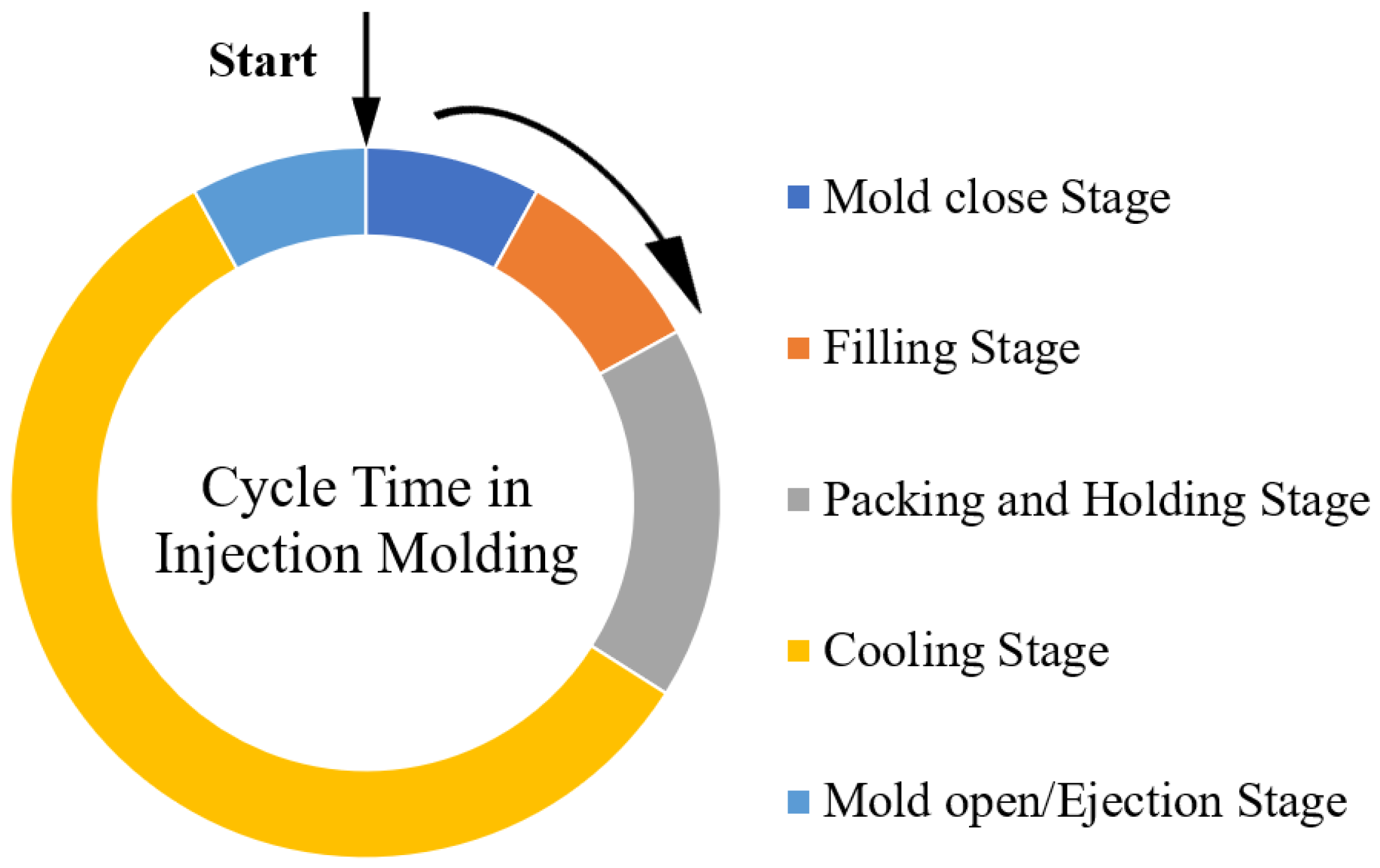
The injection molding process consists of five stages, as shown in Figure 1: mold opening (ejection), mold closing, filling, packing, and cooling [1]. Among the above stages, the cooling stage is the most important because it significantly affects the productivity and quality of the formed parts [2,3]. The cooling stage generally accounts for a majority of the injection molding cycle. In injection molding, short cycle times are important for high productivity. Proper cooling channel design can significantly reduce cooling time and increase the productivity of the injection molding process. PIM also requires high-quality products. From the perspective of dimensional accuracy and appearance, the main defects of PIM should be avoided as much as possible, including warpage, volume shrinkage, and weld lines [4,5]. An efficient cooling system that achieves uniform temperature distribution can minimize undesirable defects that affect the quality of the molded parts, such as hot spots, sink marks, differential shrinkage, thermal residual stress, and warpage.
The cooling system is an important part of the injection mold and has the function of adjusting the temperature of the mold. Mold temperature has an important impact on the quality and forming efficiency of injection-molded products [6,7]. As plastic melts flow, a mold temperature that is too low increases the shear force and internal stress, resulting in defects such as short shots and flow marks; on the contrary, a mold temperature that is too high results in defects such as short shots and flow marks. The plastic melt is prone to decomposition, leading to reduced precision and color changes in the final product. Additionally, uneven temperatures in the mold can cause cooling discrepancies between different parts of the product, resulting in temperature-induced stress, and secondary shrinkage of the product after demolding can have a large gap, resulting in warping and deformation. Products with an uneven wall thickness and complex shapes have a greater impact. Therefore, facing the development requirements of high-efficiency and high-quality injection molding, the optimization design technology of injection mold cooling systems has become the research mainstream of current injection mold design technology.
The importance of the cooling process in injection molding has attracted a great deal of attention from plastics engineers and researchers. Some researchers have focused on the analysis of cooling systems and how to optimize the layout of cooling channels in terms of their size and position by means of mathematical calculations and analytical methods. These practical methods are reported to be more convenient and faster than the finite difference method and finite element method (FEM). They require less work from the plastics designer than numerical and analog software. These methods can be applied to simple molded parts. Other methods use the 2D boundary element method and sensitive analysis combined with gradient optimization algorithms or hybrid optimizers to optimize cooling channel systems. More recently, the application of 3D CAE and 3D FEM computer-aided simulations has been widely used to study the thermal behavior of cooling systems and the configuration of conformal cooling channels. The results of these studies [6,8] have shown that shaped cooling channels have shorter cooling times and better temperature distribution than conventional cooling channels. Park and Pham [9] introduced an optimization strategy and investigated certain types of shaped cooling layouts for automotive parts by applying analytical formulations. They used CAE flow simulations to validate the optimization results and to demonstrate the cooling effect of the shaped cooling channels.
To achieve a consistent temperature distribution, it is essential to align the cooling channels with the surface of the mold cavity. The utilization of this approach relies on advancements in solid freeform (SFF) manufacturing technology, allowing for precise and uniform cooling channel placement. A number of works have investigated the advantages of the conformal cooling system and how to optimize the conformal cooling channels in injection molds. The results report that the conformal cooling channels provide better temperature uniformity and better-molded part quality within the mold cavity compared to straight cooling channels. SFF or rapid prototyping technology offers the opportunity to create very complex cooling channels in the core and cavity, but this technology is still very expensive, especially for large molds. On the other hand, there is a limited range of metal powders available for additive technologies, such as 3D printing, selective laser sintering, electron beam melting, and laser-engineered net forming. This means that the choice of mold materials with the right thermal and mechanical properties for the manufacturing of conformal cooling channels by SFF is narrower than for conventional molds. The issues have prevented the widespread use of additive technologies in the manufacturing of large injection molds.
This paper aims to solve the persistent problem by introducing an optimized conformal cooling channel. The relationship between the cooling channel configuration and the average thermal behavior of the mold cavity cycle is investigated in depth. The layout of cooling channels for quite complex molded parts is optimized by combining simplified models, computer-aided 3D heat transfer analysis, and an effective optimization strategy. As a result, this approach will provide a more feasible and practical way to design optimal conformal cooling channels, reduce cooling time and improve the quality of molded parts with less work.

2. Conformal Cooling Channel

Conformal cooling channels are different from conventional cooling channels. In a conventional cooling channel, the free-form surface of the cavity is surrounded by straight channels. The cooling channels are at different distances from the cavity surface, resulting in uneven cooling. On the contrary, in a conformal cooling channel, the cooling channel is well matched to the cavity surface by maintaining an almost constant distance between the cooling channel and the cavity surface. Many conformal cooling channel layouts [10,11,12,13] have been proposed in previous research. The cooling channel provides better temperature distribution in molded parts than conventional cooling channels.
The main purpose of the design of the cooling channel is to keep the cooling channels inside the injection mold as close to the surface of the product as possible, so that the temperature distribution on the surface of the product is more uniform, eliminating heat collection areas, and ultimately resulting in more uniform cooling, shorter molding cycles, and higher molding quality of the part. With the rapid development of 3D printing technology and prototyping technology and the gradual reduction of manufacturing costs, the application of conformal cooling channel design technology has become increasingly mature and common. Conformal cooling channels are often used in the design of cooling systems for injection molded products with large curvature changes and uneven wall thickness distribution. The production of cooling channels mainly uses the following technologies. The first is direct metal laser sintering technology, which uses a laser to sinter metal powder layer by layer to form the cavity or core part of the mold. The second is thermal or pressure fusion technology, which uses heating or pressure to fuse two or more metal plates in a vacuum furnace. The third is laser 3D printing molding technology. Based on computer software layered discrete and CNC molding system, 3D printing and manufacturing of mold inserts are performed by using a high-energy laser beam and high-temperature fusion nozzles to process and manufacture templates with computer-simulated 3D models by stacking and bonding metal, and ceramic powder and special injection molding raw material. The purpose of traditional manufacturing industry is to shape the product through processing and manufacturing methods such as injection molds, lathes, and milling machines, and then to cut excess materials to manufacture injection molded parts. However, 3D printing technology can convert the three-dimensional design in the computer into a physical model, directly manufacture parts or molds, and save materials without removing scraps. It improves the utilization of materials and effectively shortens the product development cycle time.
Optimization of the injection mold cooling system is mainly reflected in the improvement of the numerical simulation technology of the injection mold cooling process and the layout optimization of the cooling channels.
Agrawal Kamal Kumar et al. [14] proposed a method for the optimization of mold cooling systems based on hydrodynamic simulation. They concluded that the selection of cooling system arrangements mainly depends on the temperature reduction of the system, heat transfer rate, and ease of manufacturing and installation, and they verified the feasibility of the method by numerical simulation.
Choi et al. [15] from Korea designed an automated optimization method for cooling channels. Using spectacle lenses as the research object and the surface temperature deviation value of the plastic part as the optimization index, the conformal cooling channels were designed and optimized by imitating the growth mechanism of plant roots. This method first decomposes the injection molded part into small areas according to the CVD algorithm and then connects the central part of heat to form the cooling channel module according to the binary branching law. The simulation results showed that the temperature deviation of the injection-molded product was successfully reduced by about 30% by using the evolutionary optimization design method, which improved uniformity of the mold temperature distribution and reduced volume shrinkage of the molded part.
Venkatesh et al. [16] used a similar optimization method to simulate and evaluate the thermal performance of a single-cavity injection mold by considering the uniformity of mold temperature distribution and the cooling time of injection-molded products as optimization indexes, and the thermal performance of a single-cavity injection mold was simulated and evaluated by the thermodynamic coupling module of ANSYS R15.0 software. Venkatesh’s design method solves the shortcomings of the single-objective optimization method and achieves multi-objective optimization of the mold’s temperature distribution uniformity and cooling time, which has better practicality.
Based on COMSOL 5.0 simulation software, Wu et al. [17] in the United States implemented topological optimization of the parameters of the three-dimensional model of the product according to thermodynamic theory and solved the cooling channels’ design parameters according to the derivative-free optimization solution method, and by solving the thermodynamic topological optimization problem, the structural distribution of the multi-phase lattice was optimized by optimizing the cell lattice distribution so that the injection mold can be lightweight and ensure its structural strength at the same time. Compared with other optimization methods for designing the channels, this method can improve the structural stability of the injection mold while ensuring the quality of the design for the cooling channels.
Jahan (USA) and Venkatesh (India) [18] used the experimental design method to optimize the design parameters of the conformal cooling channels. The corresponding optimized design parameters of the conformal cooling channels were finally derived.
Dong-Gyu Ahn [19] from the University of Chosun, Korea, designed and fabricated conformal cooling channels in a mold with a fan as the optimization object. The results showed that the cooling efficiency of the mold could be improved by up to 35% by designing a conformal cooling channel. In the same year, Xuan Phuong and H.S. Park [20] of the University of Ulsan, Korea, used the conventional drilling and milling method to create a U-groove structure with an array of spacer plates to better match the surface profile and shape distribution of the molded part. The advantage of this method is that it is relatively simple, but there will be water leakage. The manufacturing cost is lower than 3D printing but higher than traditional cooling methods.
Ismet [21] from the University of Leeds, United Kingdom, used selective laser sintering to produce a sample of a mold core and cavity containing a conformal cooling channel, showing that the design of conformal cooling channels in the mold improved both the molding quality and dimensional accuracy of the plastic part. Saifullah et al. [22] in Australia used 3D software to model the plastic part and then simulated the injection molding process using ANSYS software. Then, the mold model was imported into Moldflow software for meshing, constructing the casting system and cooling system, and simulating the whole injection molding process. By comparing and analyzing defects such as volume shrinkage and warpage deformation, the optimal combination of injection molding process parameters is finally obtained. The simulation results show that the conformal cooling channel of an injection mold can greatly improve the molding quality of plastic parts.
Agazzi et al. [23] of the University of Nantes, France, designed the shape and diameter of the conformal cooling channels by determining the surface temperature distribution of the cavity based on a conjugate gradient algorithm. For the local heat collection area of the cavity, the diameter of the cooling channels was increased or designed as a water tank for local cooling.

3. Analysis of the Cooling Mechanism of Injection Mold

3.1. Analysis of Temperature Field of Injection Mold

The injection molding process is a cyclic process, which means that the whole process of mold temperature field change also belongs to the cyclic change process. At the beginning of the cycle, the transient temperature of the mold cavity surface changes periodically according to the change in the production cycle. On the other hand, the average temperature of the mold cavity surface gradually rises, and the product quality at this stage is unstable. After completion of this stage, the stable working condition is satisfied so that the plastic parts can be produced at high quality. The transient temperature of the injection mold cavity surface maintains a cyclic state, but the average temperature is maintained at a constant value during each cycle.
In the plastic-forming process, the entire mold can be regarded as a heat exchange system. Most of the heat is carried to the gate of the mold-forming machine and is transferred to the cooling system by the high-temperature melt ejected from the injection molding parts, where the cooling medium takes away the heat. The remaining heat is transported to the environment using heat radiation and heat convection through the outer surface of the mold. Then, 90–95% of the heat is carried away by the melt by the cooling medium in the cooling channel. Heat transfer between the plastic melt and the mold occurs on the surface between the mold cavity and the core. Since the temperature of the plastic melt is relatively high at the initial stage of injection and the surface temperature of the mold is room temperature at the initial stage of injection, heat transfer at this stage is mainly carried out through heat. The ratio of heat conduction and heat transfer is small, and the heat transfer effect good enough such that it can be ignored at this stage. Mold heat transfer is divided into three parts: (1) After the melt body contacts the surface of the cavity, part of the heat is brought to the mold through heat conduction. (2) The coolant absorbs most of the heat from the cooling channel inside the mold and then removes the heat through convection heat exchange. (3) Heat dissipation occurs through direct contact between the outer surface of the mold and the surrounding air, and heat is carried out through the process of convective heat transfer and radiation heat transfer.
From the above analysis, according to the law of conservation of energy, the heat balance equation of the mold in stable working conditions is obtained as follows:
Q ˙ p + Q ˙ c + Q ˙ a 0
where  Q ˙ p  is the heat transfer between injection molded products,  Q ˙ c  is the convective heat exchange between the mold and the cooling system, and  Q ˙ a  is the convective heat exchange between the mold and the surrounding environment.
In Figure 2, when the molten polymer is injected into a mold, its heat is dissipated by the cooling medium flowing through the mold’s channels and the environment surrounding the mold’s surface. The heat exchange between the cooling medium and the mold occurs mainly through convection, while the heat exchange between the mold and the environment happens through a combination of convection and radiation from the mold’s side surfaces. In addition, some heat is conducted into the injection molding machine.
To simplify the energy balance equation, we only consider the heat transfer between the mold, the cooling medium, and the plastic product through thermal conduction and convection, and we approximate the radiative heat transfer from the mold’s outer surface. This approximation is justified because the heat lost through radiation from the mold’s outer surface is negligible compared to the total heat, accounting for less than 5%. Thus, we assume that the heat exchange mainly occurs between the molten polymer and the cooling medium, and by neglecting the heat lost to the surrounding environment, we can simplify the energy balance equation.
Q ˙ p + Q ˙ a 0
where the heat flux from the molten plastic into the coolant can be calculated as [24]:
Q ˙ p = 10 3 c p T M T E + l h ρ θ 2 x
where  c p  is the specific heat of the part material,  T M  is the melt temperature,  T E  is the ejection temperature,  l h  is the latent heat of the part material,  ρ  is the density of the part material,  θ  is the thickness of the plastic part, and x is the pitch between the centerline of the cooling channels, respectively.
The heat transfer between the mold and the coolant, occurring over a period  t c , can be quantified as the heat flux [25],
Q ˙ a = 10 3 t c 1 10 3 α π d + 1 λ m S c 1 T W T C
where d is the diameter of the cooling channel,  λ m  is the thermal conductivity of the mold steel,  S c  is the shape factor of the cooling channel,  T W  is the average temperature of the mold surface,  T C  is the temperature of the coolant, and a is the thermal diffusivity of the part material.
α = λ m ρ c p
The impact of the cooling channel position on heat conduction is analyzed by incorporating the concept of shape factor [26]:
S c = 2 π ln 2 x   sin h 2 π y x π d
where y represents the radial distance from the center of the cooling channel to the surface of the mold. The heat transfer coefficient of the coolant is calculated by [27]
h = 31.395 d R e 0.8
where the Reynolds number is
R e = ρ u d μ
where  ρ  is the coolant density, u is the average flow velocity of the coolant in the pipe, and  μ  and is the coolant viscosity.

3.2. Analysis of the Heat Exchange between the Mold and the Cooling System

The convective heat exchange process between the mold and the cooling system is achieved in two main ways: one is to carry away the heat through the continuous flow of coolant in the cooling channels, which is convective heat exchange; the other is through heat transfer by transferring part of the heat to the contact surfaces of the coolant and the temperature difference between the cooling channels; the convective heat exchange process is influenced by many factors, and its calculation formula is:
q = h ( T W T C )
In this formula,  T W  is the average temperature of the cooling channel wall,  T C  is the temperature of the coolant, and h is the convective heat transfer coefficient, the size of which is mainly related to the flow state of the coolant in the cooling channels. This relationship is mainly reflected in the Reynolds number  R e . In the actual production of injection molding, achieving an exuberant turbulent flow state with a Reynolds number (Re) greater than 10,000 is crucial to ensure that the convective heat transfer coefficient is within the desirable range.
Figure 3 depicts two distinct flow regimes in pipe flow, laminar and turbulent flow. Laminar flow is characterized by a Reynolds number (Re) below 2300, while the transition state occurs between Re values of 2300 and 4000, and turbulent flow is observed when Re exceeds 4000. In laminar flow, where viscous forces dominate over inertial forces, velocity disturbances are attenuated by viscous forces, resulting in a stable flow field. Conversely, in turbulent flow, where inertial forces prevail over viscous forces, flow instability is increased, with small changes in velocity leading to the development and enhancement of irregular turbulent flow fields.

3.3. Heat Transfer Analysis of the Cooling Channel of the Injection Molding

3.3.1. Cooling Channel Heat Transfer Mathematical Model Establishment

During the cooling process of plastic parts, the coolant flow in the channel is three-dimensional but can be simplified to a one-dimensional steady-state flow process when analyzing heat transfer behavior. Therefore, it is not necessary to study the precise details of the coolant flow. In the modeling process, parameters such as coolant flow rate and pressure can be regarded as remaining constant along the length of the cooling channel but may vary with changes in the channel geometry or coolant properties.
Based on the analysis above, it is clear that convective heat transfer is responsible for heat transfer between the mold and cooling channels. The third boundary condition is applied in the boundary analysis model for cooling channels, which requires calculation of the convective heat transfer coefficient of the coolant. This coefficient is closely related to the flow conditions of the coolant. When the coolant flows uniformly into the channel with a Reynolds number  R e  greater than a critical value, the boundary layer inside the channels will gradually rise to a turbulent boundary layer and will subsequently flow into the center of the channels and become a fully turbulent zone.
At a uniform flow rate, when the coolant is forced into a circular tube with a Reynolds number (Re) surpassing the critical value, gradual development of a turbulent boundary layer occurs at the pipe’s boundary. This turbulent boundary layer then converges toward the center of the tube, eventually establishing a fully developed turbulence zone.
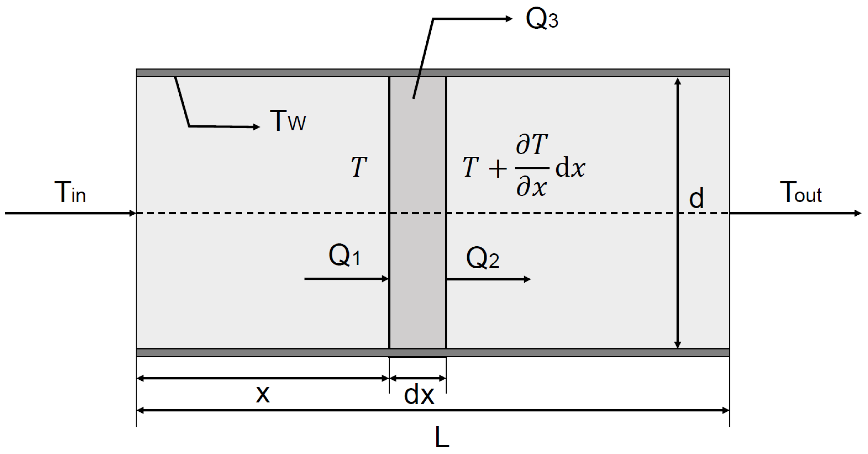
Consider that the coolant is located in channels of length L flowing. The inner wall temperature  T W  of the channels is kept constant. The inlet and outlet temperatures of the cooling channels are  T i n  and  T o u t , respectively, and the coolant flow rate is v. Figure 4 represents a schematic diagram of the heat balance of the coolant in a micro-element control body of length dx. Assuming that the average temperature of the coolant at the cross-section from the inlet x is  T a , the heat flow  Q 1  obtained by the micro-element is:
Q 1 = ρ c v T A
where  ρ  is the coolant density, c is the specific heat capacity, A is the cross-sectional area of the channels, and
A = π 4 d 2
Similarly, the heat flow  Q 2  out of the micro-element and the heat flow  Q 3  from the inner wall of the channels to the micro-element can be obtained as:
Q 2 = π 4 d 2 ρ c v ( T + d T d x )
Q 3 = h ( π d d ˙ x ) ( T W T )
where h is the convective heat transfer coefficient that can be computed as:
h = 0.027 ( v d ρ μ ) 0.8 ( c μ λ ) 1 3 ( μ f μ W ) 0.14 λ d
where  μ W  is the viscosity of the cooling liquid when the wall temperature is  T W , and other parameters are determined by the average temperature of the coolant.

3.3.2. Calculation of Cooling Process

Calculating the cooling process in plastic injection molding comprises three essential aspects: determination of the cooling time for the plastic part within the mold, optimization of the flow rate of the coolant, and principled arrangement of the cooling channels. The cooling time of the plastic part refers to the time taken for the melt to fill the cavity and meet the requirements for demolding, which includes achieving full cure, required strength and stiffness, and preventing deformation or cracking during ejection. Among these factors, achieving a complete cure of the plastic part is a key criterion for successful molding.
(1) The temperature at the center of the maximum wall thickness of the plastic part is lower than the heat deflection temperature of the injection material;
(2) The average temperature in a cross-section of the plastic part is lower than the required ejection temperature of the plastic part;
(3) The temperature at the center layer of the thickest part of the plastic component must reach the solid melting point or the required percentage value of the crystallinity for crystalline plastics.
Assuming that the temperature at the center of the maximum wall thickness of the plastic part is lower than the heat deflection temperature of the injection material required for the cooling time, then there is [28]:
t c = δ 2 π 2 α ln 4 π T M T W T E T W
where  θ  is the thickness of the plastic part,  T M  is the melting temperature of the plastic part, W is the temperature of the mold cavity surface,  T E  is the ejection temperature of the plastic part, and  α  is the heat diffusion rate of the plastic, defined as  α = λ . The cooling time of the plastic part is [20]:
t = c ( T M T E ) ρ l θ 2 T W T C { 1 2 π λ m ln 2 l sin ( 2 π s ˙ l ) π d 1 0.032 R e 0.8 }
This is only suitable for finding the cooling time at a certain point on the plastic part.

4. Cooling System Design and Cooling Simulation Based on UG and Moldflow

4.1. Establishment of Finite Element Model

4.1.1. Model Simplification and Meshing

Meshing the plastic part is a primary process. Moldflow offers three types of meshing, including mid-plane meshing, double-layer meshing, and 3D meshing. Among these options, the mid-plane mesh model is particularly suitable for injection-molded products with small and uniform thicknesses, simple structural distribution, and various locations of thickness distribution. Additionally, this type of meshing results in a relatively low number of meshes after the division process. A double-layer mesh model is a widely used option in Moldflow, allowing for simulation of both the top and bottom of the melt flow. By using this model, injection molding processes can be accurately simulated to yield high-quality mesh and faster processing times. As a result, it is an effective tool for optimizing the structural and mold design of plastic parts, leading to improved simulation results. The three-dimensional model of the product is depicted in Figure 5. The maximum thickness of this product is 2.11 mm, and the average thickness is less than 2 mm. Subsequently, after performing meshing on the model, we obtain Figure 6.
Meshing the plastic part using a 3D mesh model in Moldflow is an effective way to accurately simulate the injection process in the entire 3D space, allowing for a realistic representation of the filling process. Since the outer surface of the plastic part typically has a complex structure with an unevenly distributed wall thickness, a 3D mesh model is necessary. The edge length of the mesh is primarily determined by the thickness of the plastic part, the fit quality of the mesh, and the shape accuracy of the plastic part. Generally, it is 1.5–2 times the thickness of the plastic part to ensure analysis accuracy.

4.1.2. Moldflow Cooling Analysis Type Selection

The cooling process of the injection mold is a three-dimensional transient heat transfer process, and the transient temperature of the mold surface varies periodically with the injection process. In practical engineering applications, it is generally reduced to a steady-state heat transfer process. Among the cooling analysis types in Moldflow, the main types include BEM cooling analysis and FEM cooling analysis.
The boundary element method (BEM) is a numerical approach used to analyze the cooling process of plastic parts in injection molding. BEM cooling analysis is utilized to determine the average temperature of the plastic part during the steady state or the entire molding cycle. In the cooling simulation, the boundary element method cooling analysis can easily change the position of the cooling channel, obtain an effect of the position of the cooling channel on the cooling effect of the mold, and optimize the design of the cooling channel. The FEM cooling analysis calculates both steady-state and transient temperatures of the mold by the finite element method. In the steady state, the mold temperature is uniform, while in the transient state, the mold temperature varies with time.
The finite element method (FEM) cooling analysis employs two main methods to analyze transient temperatures in molds: intra-cycle transient and transient after the start of production. Intra-cycle transient analysis simulates temperature fluctuations in the mold during a single cycle and calculates the deviation of the mold temperature from the cycle’s average value. This analysis helps to identify and mitigate potential temperature-related issues during production. The other method, transient after the start of production, evaluates temperature changes in the mold after production has begun. These two types of analyses are commonly used in finite element cooling analysis to comprehensively understand and optimize the temperature dynamics of molds during different phases of production.
The post-start transient calculates the change in mold temperature from the initial production cycle in the cold state to the time when the mold temperature stabilizes and reaches its optimal conditions, and it calculates the number of cycles required for the mold to reach its optimal production conditions. In order to accurately simulate and predict the temperature distribution of the mold cavity walls, this paper employs the FEM cooling analysis type for cooling simulation.

4.2. Selecting the Proper Type of Conformal Cooling Channels for Thin-Wall Products

Owing to the geometric liberty afforded by rapid metal processing techniques, such as selective laser sintering and selective laser melting, the fabrication of conformal cooling channels with versatile cross-sectional profiles and geometries is feasible. Among the prevalent options, spiral-shaped conformal cooling channels are commonly deployed due to their ability to maintain near-constant coolant velocity, despite their potential for elevated pressure drop. Conversely, scaffolded conformal cooling channels and Voronoi diagram channels exhibit lower pressure drops but pose challenges in achieving uniform coolant velocities, which may result in stagnation in certain channel segments.
The impact of a channel cross-section on cooling performance was investigated by Jahan et al., who found that rectangular channels demonstrate superior cooling performance. However, this type of cross-section may not fully align with the manufacturability requirements of additive manufacturing methods. On the other hand, elliptical, circular, and teardrop cross-sections are characterized by easier printability, without the need for support structures and stress concentrations.
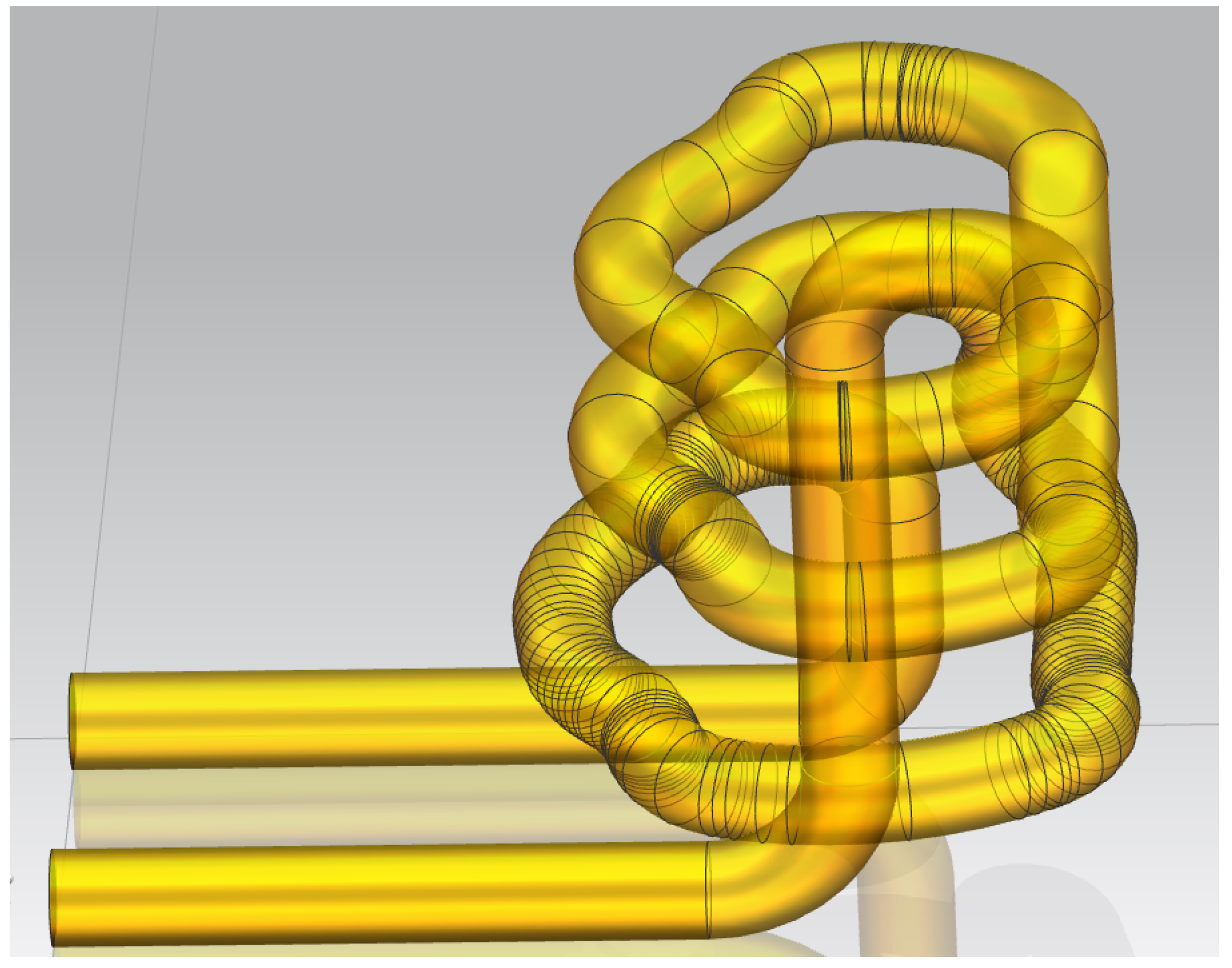
Considering the cylindrical shape of the target product, and taking into account the aspects of product shape, manufacturing cost, and feasibility of production processes, we chose spiral-shaped cooling channels with circular cross-sections. Figure 7 displays the model of simple spiral-shaped cooling channels.

4.2.1. Design Principles and Specifications of Cooling Channels

Effective cooling channel design for injection molding often involves dividing the mold into several geometrical features, with separate channels designed and laid out for each feature. These features are then combined to form the complete cooling system for the injection molding process. In order to balance mold manufacturing and plastic part production costs, injection cooling system molds typically use a combination of straight-through and shaped cooling channels. Conformal cooling channels are mainly used for complex curved features of plastic parts or for deep cavity features where conventional cooling channels cannot achieve the cooling effect. Additionally, conformal cooling channels are often utilized for injection molds with moving parts and complex ejection systems.
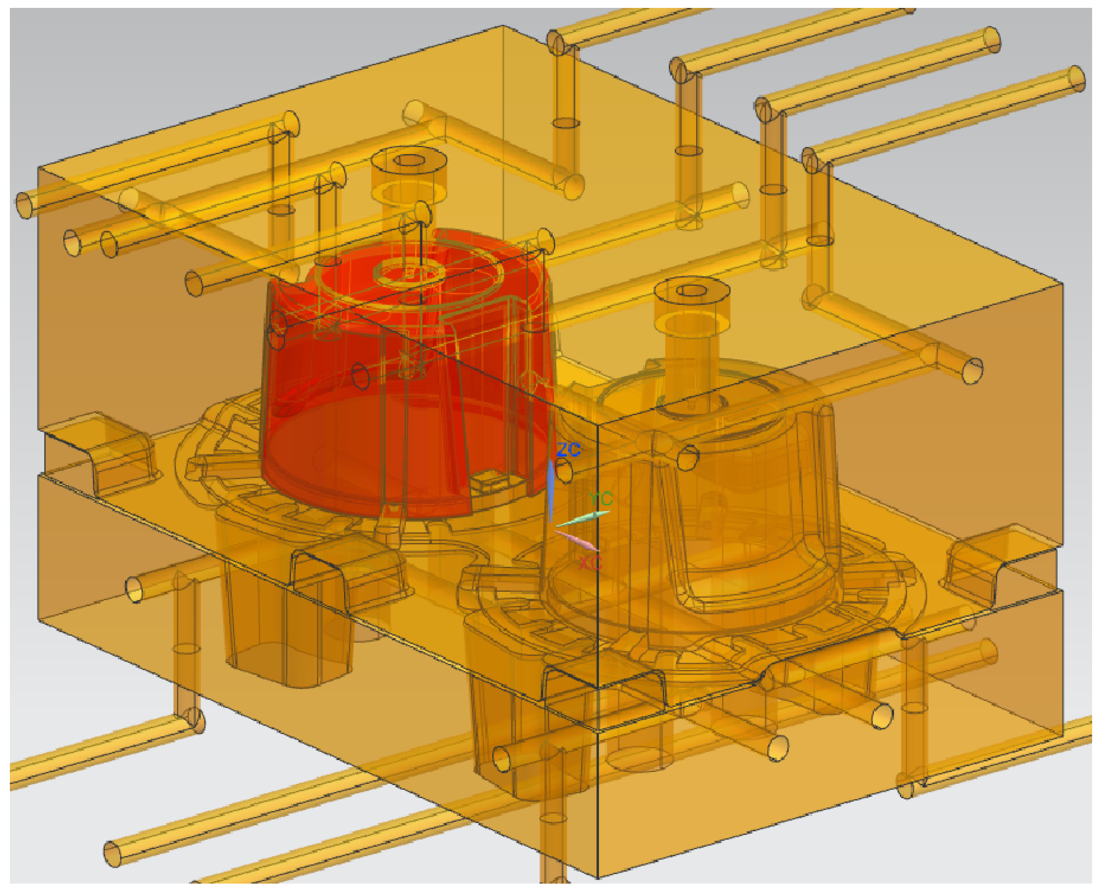
The layout of cooling channels in molds is often limited by the mold’s intricate surface features and complex structure. As shown in Figure 8, a conventional pipeline model is shown. The channels are all the straight-drilled type. In practice, the design of cooling channels cannot always be achieved according to the ideal design scheme due to these limitations. As a result, mold designers need to have the expertise to continually modify the plastic part to match the shape, size, wall thickness, and structural characteristics of the cooling water channels. This requires a deep understanding of the manufacturing process and the ability to optimize the design of cooling channels to ensure optimal performance of the mold. The cooling channel design principles and specifications are as follows. Figure 9 displays the local geometric configuration of conformal cooling channels, which exhibit a more complex shape that conforms closely to the shape of the product.
(1) The distance between the centerline of the cooling channel and the cavity wall is a critical consideration in mold design. When the product thickness is uniformly distributed, it is essential to maintain a consistent distance between the cooling channel’s centerline and the cavity wall throughout. However, when the product thickness is unevenly distributed, it is necessary to decrease the distance between the cooling channel’s centerline and the cavity wall in the thicker areas to ensure that the product cools uniformly. This is particularly important to prevent warpage and deformation and to achieve the desired product quality. Therefore, careful consideration of the cooling channel layout is crucial to achieve optimal mold performance and to ensure consistent product quality.
(2) Cooling channel layout: There are two types of layouts, namely series and parallel layouts. When cooling channels are connected in series, the coolant flow rate remains basically unchanged, but under the complex cooling channel layout, the channel loss value and pressure drop are larger. When cooling channels are connected in parallel, the flow rate in each branch cooling channel is different, resulting in uneven cooling of plastic parts. Therefore, in order to avoid encountering the problems of the parallel connection method, the series layout method should be given priority.
(3) Cooling channel length: increasing the length of the cooling channel will increase the heat transfer area of the channel, and when using a series cooling channel in a series layout, the longer channel may lead to an excessive pressure drop of the coolant; therefore, the channel length should not be too long.

4.2.2. Cooling Channel Design and Modeling

In the injection molding process, because the traditional straight-drilled cooling channels cannot effectively cool the slider and insert it into the deep cavity of the plastic part, this can result in local heat concentration in the plastic part, ultimately affecting the overall cooling time.
Therefore, we need to establish the model of the conformal cooling channel and compare the cooling efficiency with the traditional cooling channel through the simulation analysis results.

4.3. Cooling Process Simulation and Analysis

According to the above cooling channel design plan, the cooling simulation analysis was carried out using Moldflow simulation software.

4.3.1. Parameter Setting

According to the requirements of the recommended molding conditions of the plastic parts, the injection process parameters were set as shown in Table 1. During the injection molding process, common processing parameters include temperature, pressure, injection time, holding pressure time, and cooling time. Temperature adjustment is crucial to ensure the melting and flowability of plastic materials, involving control of the melt temperature and mold temperature. Pressure plays a significant role in pushing the molten plastic material into the mold. Adjusting the injection time and holding pressure time is essential for complete filling, solidification, and stability of the plastic material. Cooling time refers to the time the product remains in the mold for cooling after the injection molding process. Proper cooling time ensures proper solidification and strength development of the product while minimizing deformation and warpage. The adjustment of these processing parameters is critical for the success and optimization of the injection molding process.

4.3.2. Design of Experiments for Optimized Conformal Cooling Channels

The experimental design methodology was employed as a guiding framework for the development of conformal cooling channels. The design process encompassed a comprehensive experimental approach, taking into consideration the thin-walled characteristic of the products with wall thicknesses typically ranging from 0 to 2 mm, as well as the diameter of the cooling channels, which was determined based on the specified boundary conditions, falling within the range of 4–6 mm. The initial experimental design of DOE-1 was established based on general rules of thumb for mold designers. In this set of experiments, circular cross-sections were employed for all the cooling products, and the specific details of the DOE parameters can be found in Table 2. The design cases were denoted as 1.1, 1.2, and so forth, in accordance with the experimental design plan.
We enhanced the experiments conducted on DOE-2, DOE-3, and DOE-4 by incorporating various channel cross-sectional shapes, including trapezoidal, dome, and rectangular, as shown in Table 3. To maintain a consistent cross-sectional area, these shapes were derived from circular cross-sections by keeping the area constant and by recalculating the dimensions. For instance, if the diameter of a circular cross-section is 6 mm, its area would be 28.27 square millimeters. This area can be converted to other shapes, such as a rectangular cross-section with dimensions of 5.3 × 5.3 mm, a trapezoidal cross-section with a top width of 4.0 mm, a bottom width of 5.0 mm, and a height of 6.3 mm, or a dome-shaped cross-section with a width of 8.0 mm and a width of 5.0 mm. However, the exact value of the dome-type cross-sectional area is challenging to calculate; thus, an approximate value is used.
Based on the classification of cross-sectional shapes, we conducted five sets of experiments with different cross-sectional areas that matched the areas of circular cross-sections with diameters of 4.0, 4.5, 5.0, 5.5, and 6.0 mm. For example, for rectangular cross-sections, we designed cross-sectional areas of 4.1, 4.2, 4.3, 4.4, and 4.5 while maintaining the same area as the corresponding cross-sections of other shapes. Table 4 presents the optimization problem statements for DOE-1, DOE-2, DOE-3, and DOE-4, along with their corresponding conformal cooling channel shapes: circular, trapezoidal, dome-shaped, and rectangular, respectively. Additionally, the table provides an illustration of the design variables and constraints.

4.3.3. Analysis and Comparison of Cooling Results

Based on the establishment of the cooling system model, the selection of injection process parameters and the establishment of the mold gating system mentioned above, the cooling simulation was carried out for the two groups of cooling system design solutions.
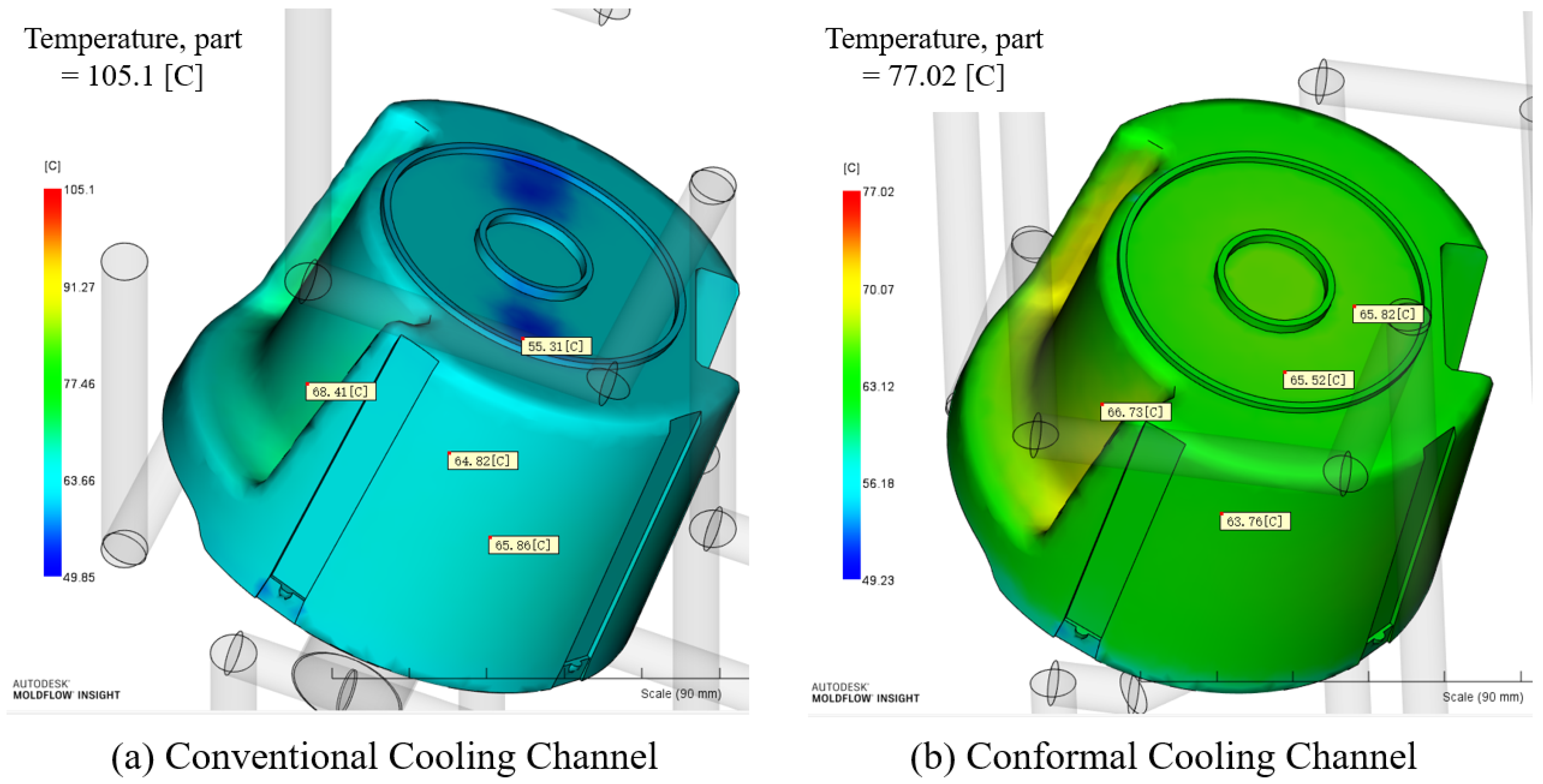
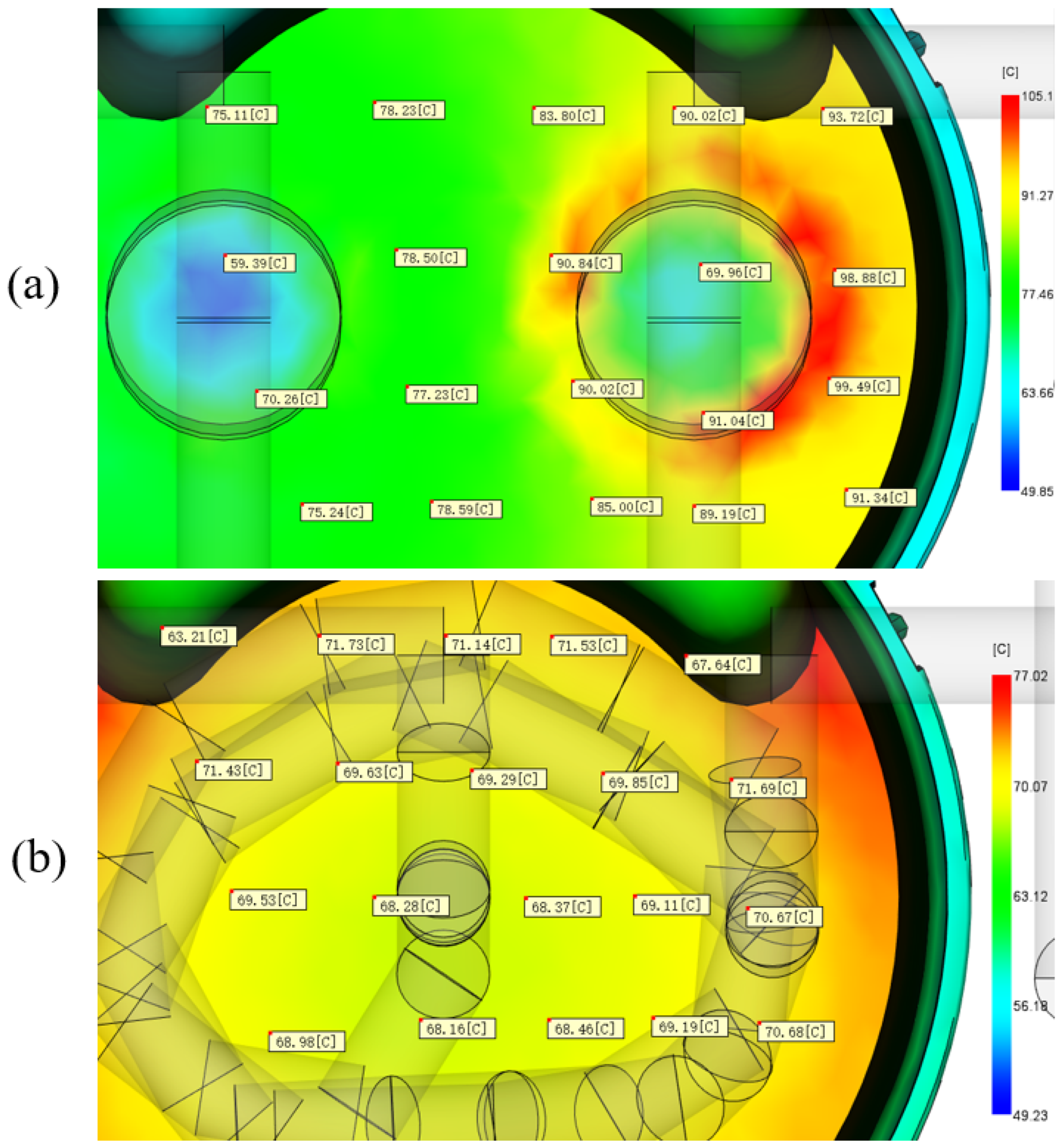
As evident from Figure 10, the simulation results reveal that the product employing the conventional cooling system attains a maximum temperature of 105.1 degrees Celsius at the end of the cooling process, whereas the product incorporating the conformal cooling channels exhibits a significantly lower maximum temperature of 77.02 degrees Celsius. The cooling system with conformal cooling channels demonstrates higher efficiency in the cooling process compared to the traditional cooling system, leading to a more uniform and lower temperature distribution of the plastic parts.
Figure 11 presents the detailed temperature distribution within the part. Based on the findings obtained from the simulation results, it is apparent that the utilization of conformal cooling channels in the product design results in lower temperatures compared to conventional cooling channels, accompanied by a more homogeneous temperature distribution. The implementation of conformal cooling channels in the product design leads to improved heat transfer efficiency from the product surface to the cooling medium. Furthermore, the arrangement of these channels has the potential to enhance the uniformity of temperature distribution on the product surface by mitigating the occurrence of hot spot areas, which are localized regions with elevated temperatures. The strategic placement of cooling channels in proximity to these hot spot areas facilitates effective heat dissipation, resulting in reduced temperature gradients and enhanced uniformity of temperature distribution.
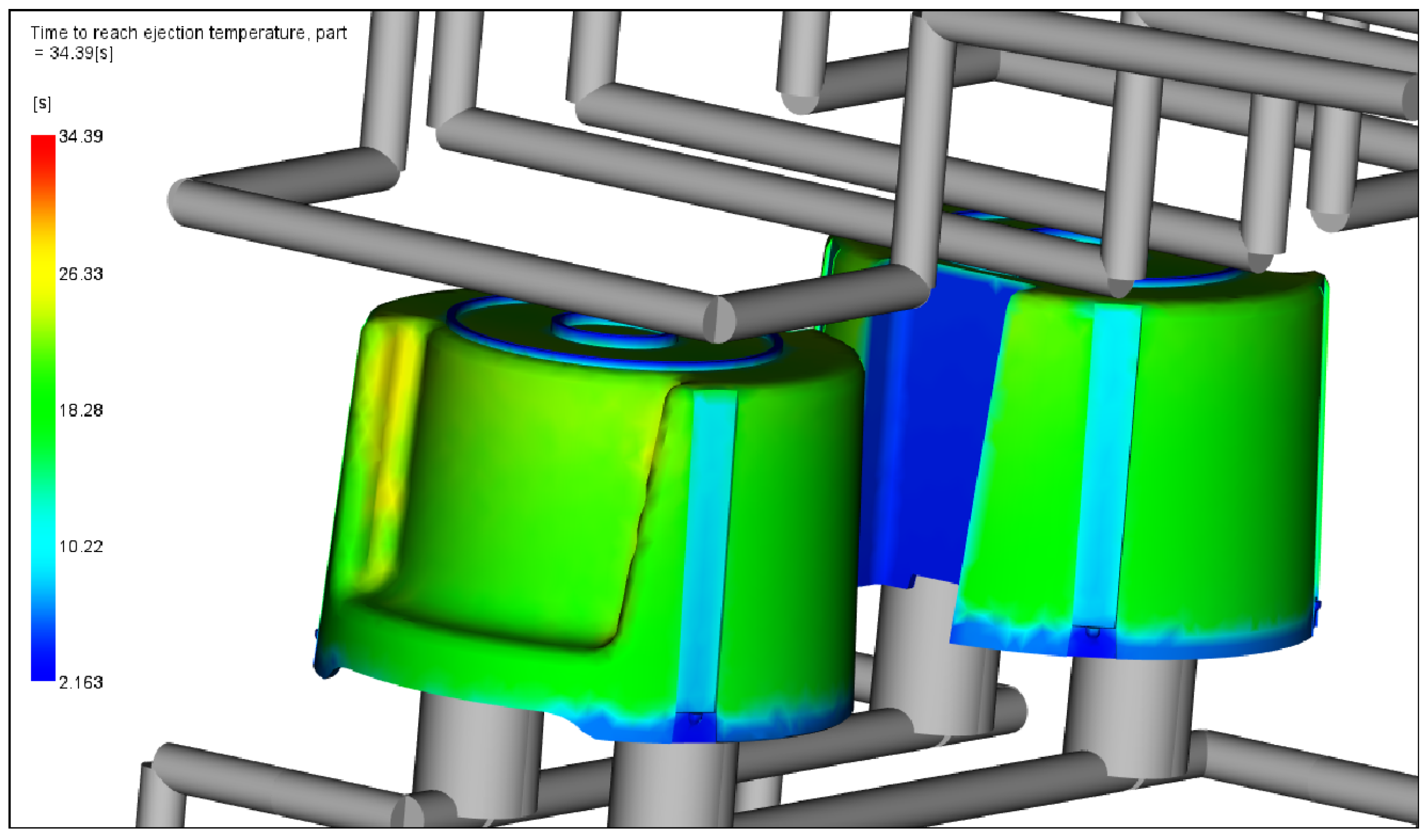
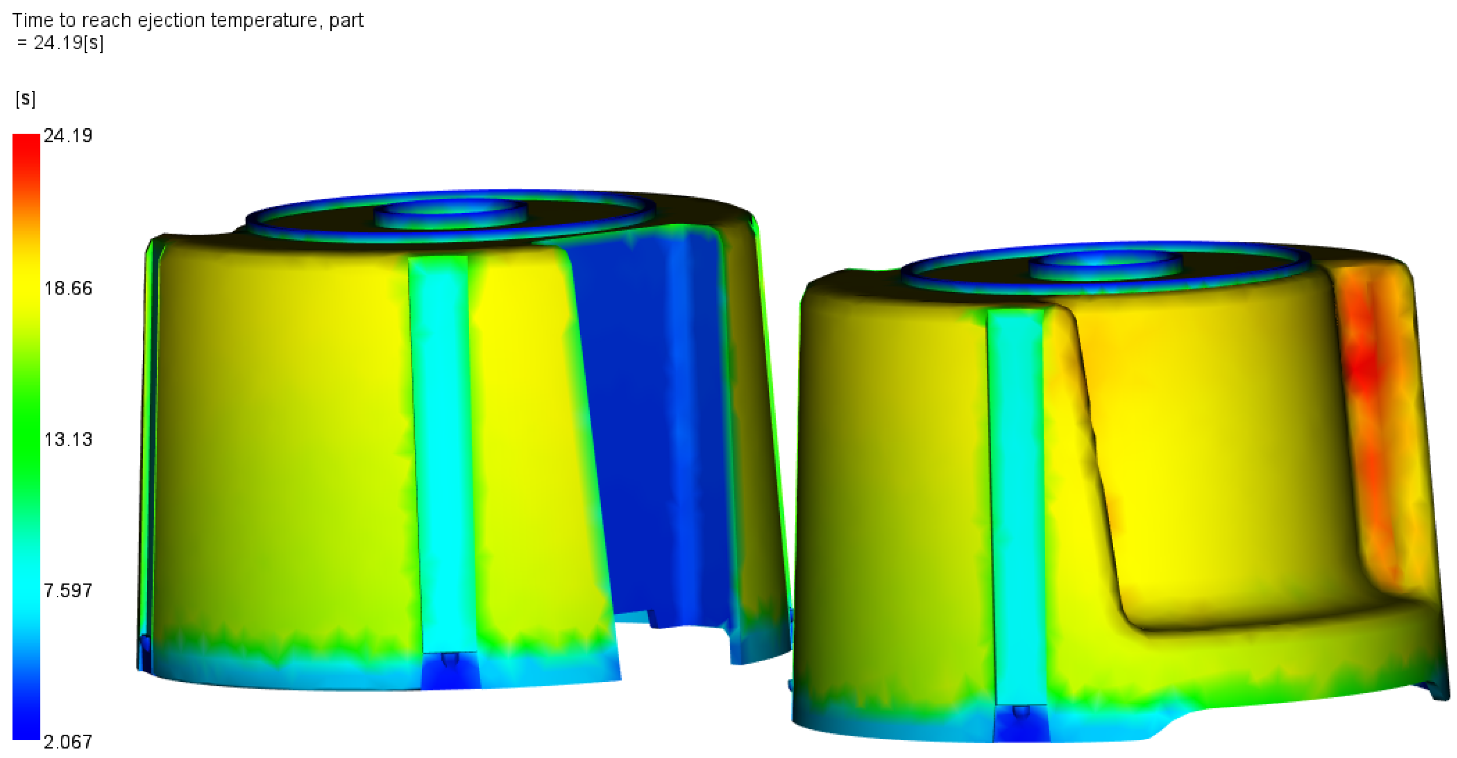
From Figure 12 and Figure 13, it is evident that the time required to reach the ejection temperature using conventional cooling channels is 34.39 s, whereas the time using conformal cooling channels is reduced to 24.19 s, resulting in a significant reduction in cooling time by 10.20 s. This reduction in cooling time underscores the superior performance of conformal cooling channels over conventional cooling channels in achieving the desired ejection temperature.
Figure 14 shows the distinct time required for various sections of the plastic parts to reach ejection temperature. Table 5 displays the statistical data for a randomly chosen point on the surface of the simulated part. The data indicate that when utilizing conformal cooling channels, the product temperatures are significantly lower compared to conventional ducts, with a temperature reduction ranging from 11 to 28 degrees Celsius. Additionally, the average time required to attain the ejection temperature of the inner corner of the plastic part is 32.29% lower with the use of conformal cooling channels as compared to conventional channels. Thus, we can calculate the cooling efficiency of the conformal cooling channel to be more than 30%.

5. Conclusions

The cooling time of the mold using conventional cooling channels is 34.39 s, while the cooling time with conformal cooling channels is 24.19 s. Therefore, the cooling efficiency increased by 29.66%. This indicates that conformal cooling channels are beneficial for reducing cooling time and for increasing production efficiency. Conformal cooling channels can significantly reduce the cooling time, achieve uniform cooling and improve the quality of molded parts, especially for large-scale and complex-geometry products. Designing and optimizing conformal cooling channels for injection molding requires a complicated analysis process, optimization strategies, and appropriate computer-aided tools. This study proposes a method to optimize the cooling system to obtain the target mold temperature and to reduce the cooling time and non-uniformity of the molding temperature distribution, as well as to increase productivity. To improve computational efficiency, analytical and simulation-based methods are used successively. The relationship between the thermal behavior of the die and the cooling channel layout parameters has been carefully investigated. The feasibility of the analytical method is demonstrated by comparing the results of this method with DOE approximations. It can be concluded that the analytical method is suitable for optimizing conformal cooling channels with moderate accuracy. The design and optimization of the conformal cooling channels can bring numerous potential advantages to the injection molding process. New materials with better thermal conductivity and high-temperature resistance also need to be considered to further improve cooling efficiency. While simulation methods play an important role in the design of conformal cooling channels, experimental validation remains indispensable. Future research can be conducted to provide more experimental validations, to verify the simulation results and to provide practical industrial applications. In conclusion, more efficient and reliable conformal cooling channels will be widely applied in the injection molding process, leading to greater benefits in the production of plastic products.
Author Contributions

Software, Y.W.; Writing—original draft, Y.W.; Writing—review & editing, Y.W.; Project administration, C.L. All authors have read and agreed to the published version of the manuscript.

Funding

The APC was funded by Prof. Changmyung Lee.

Institutional Review Board Statement

This study did not involve humans or animals.

Informed Consent Statement

Not applicable.

Data Availability Statement

Not applicable.

Acknowledgments

The authors would like to thank Changmyung Lee and the laboratory at the University of Ulsan.

Conflicts of Interest

The authors declare no conflict of interest.

References

  1. Adam, I.; Du Preez, W.; Combrinck, J. Design considerations for additive manufacturing of conformal cooling channels in injection moulding tools. Interim Interdiscip. J. 2016, 15, 35–44. [Google Scholar]
  2. Saifullah, A.B.; Masood, S. Finite element thermal analysis of conformal cooling channels in injection moulding. In Proceedings of the 5th Australasian Congress on Applied Mechanics, Brisbane, Australia, 10–12 December 2007; Engineers Australia Brisbane, Qld.: Brisbane, Australia, 2007; pp. 337–341. [Google Scholar]
  3. Dimla, D.; Camilotto, M.; Miani, F. Design and optimisation of conformal cooling channels in injection moulding tools. J. Mater. Process. Technol. 2005, 164, 1294–1300. [Google Scholar] [CrossRef]
  4. Mazur, M.; Brincat, P.; Leary, M.; Brandt, M. Numerical and experimental evaluation of a conformally cooled H13 steel injection mould manufactured with selective laser melting. Int. J. Adv. Manuf. Technol. 2017, 93, 881–900. [Google Scholar] [CrossRef]
  5. Eiamsa-Ard, K.; Wannissorn, K. Conformal bubbler cooling for molds by metal deposition process. Comput.-Aided Des. 2015, 69, 126–133. [Google Scholar] [CrossRef]
  6. Evens, T.; Six, W.; De Keyzer, J.; Desplentere, F.; Van Bael, A. Experimental analysis of conformal cooling in SLM produced injection moulds: Effects on process and product quality. In Proceedings of the AIP Conference Proceedings, Dresden, Germany, 27–29 September 2017; AIP Publishing LLC: College Park, MD, USA, 2019; Volume 2055, p. 070017. [Google Scholar]
  7. Norwood, A.; Dickens, P.; Soar, R.; Harris, R.; Gibbons, G.; Hansell, R. Analysis of cooling channels performance. Int. J. Comput. Integr. Manuf. 2004, 17, 669–678. [Google Scholar] [CrossRef] [Green Version]
  8. Blaško, M.; Tittel, V.; Ridzoň, M. Cae Analysis of Conformal Cooling Application—Case Study. Int. J. Eng. 2012, 10, 115–118. [Google Scholar]
  9. Park, H.S.; Dang, X.P. Development of a smart plastic injection mold with conformal cooling channels. Procedia Manuf. 2017, 10, 48–59. [Google Scholar] [CrossRef]
  10. Zhang, Y.; Hou, B.; Wang, Q.; Li, Y.; Huang, Z. Automatic design of conformal cooling channels in injection molding tooling. In Proceedings of the IOP Conference Series: Materials Science and Engineering, Xi’an, China, 18–20 May 2018; IOP Publishing: Bristol, UK, 2018; Volume 307, p. 012025. [Google Scholar]
  11. Tuteski, O.; Kočov, A. Conformal cooling channels in injection molding tools–design considerations. Mach. Technol. Mater. 2018, 12, 445–448. [Google Scholar]
  12. Altaf, K.; Rani, A.M.b.A. Numerical study of profiled conformal cooling channels for cooling time reduction in injection mould tools. Int. J. Eng. Syst. Model. Simul. 2015, 7, 230–237. [Google Scholar] [CrossRef]
  13. Berger, G.R.; Zorn, D.; Friesenbichler, W.; Bevc, F.; Bodor, C.J. Efficient cooling of hot spots in injection molding. A biomimetic cooling channel versus a heat-conductive mold material and a heat conductive plastics. Polym. Eng. Sci. 2019, 59, E180–E188. [Google Scholar] [CrossRef] [Green Version]
  14. Agrawal, K.K.; Misra, R.; Bhardwaj, M.; Das Agrawal, G.; Mathur, A. Computational fluid dynamics simulation based comparison of different pipe layouts in an EATHE system for cooling operation. J. Therm. Sci. Eng. Appl. 2019, 11, 51012. [Google Scholar] [CrossRef]
  15. Choi, J.H.; Kim, J.S.; Han, E.S.; Park, H.P.; Rhee, B.O. Study on an optimized configuration of conformal cooling channel by branching law. In Engineering Systems Design and Analysis; American Society of Mechanical Engineers: Copenhagen, Denmark, 2014; Volume 45837, p. V001T06A007. [Google Scholar]
  16. Venkatesh, G.; Kumar, Y.R. Thermal analysis for conformal cooling channel. Mater. Today Proc. 2017, 4, 2592–2598. [Google Scholar] [CrossRef]
  17. Jahan, S.A.; Wu, T.; Zhang, Y.; El-Mounayri, H.; Tovar, A.; Zhang, J.; Acheson, D.; Nalim, R.; Guo, X.; Lee, W.H. Implementation of conformal cooling & topology optimization in 3D printed stainless steel porous structure injection molds. Procedia Manuf. 2016, 5, 901–915. [Google Scholar]
  18. Jahan, S.A.; El-Mounayri, H. Optimal conformal cooling channels in 3D printed dies for plastic injection molding. Procedia Manuf. 2016, 5, 888–900. [Google Scholar] [CrossRef] [Green Version]
  19. Ahn, D.G.; Park, S.H.; Kim, H.S. Manufacture of an injection mould with rapid and uniform cooling characteristics for the fan parts using a DMT process. Int. J. Precis. Eng. Manuf. 2010, 11, 915–924. [Google Scholar] [CrossRef]
  20. Dang, X.P.; Park, H.S. Design of U-shape milled groove conformal cooling channels for plastic injection mold. Int. J. Precis. Eng. Manuf. 2011, 12, 73–84. [Google Scholar] [CrossRef]
  21. Ilyas, I.; Taylor, C.; Dalgarno, K.; Gosden, J. Design and manufacture of injection mould tool inserts produced using indirect SLS and machining processes. Rapid Prototyp. J. 2010, 16, 429–440. [Google Scholar] [CrossRef]
  22. Saifullah, A.; Masood, S.H. Cycle time reduction in injection moulding with conformal cooling channels. In Proceedings of the International Conference on Mechanical Engineering, Dhaka, Bangladesh, 29–31 December 2007; pp. 29–31. [Google Scholar]
  23. Agazzi, A.; Sobotka, V.; LeGoff, R.; Jarny, Y. Optimal cooling design in injection moulding process–A new approach based on morphological surfaces. Appl. Therm. Eng. 2013, 52, 170–178. [Google Scholar] [CrossRef]
  24. Rao, N.S.; Schumacher, G.; Schott, N.R.; O’brien, K.T. Optimization of cooling systems in injection molds by an easily applicable analytical model. J. Reinf. Plast. Compos. 2002, 21, 451–459. [Google Scholar] [CrossRef]
  25. Park, S.; Kwon, T. Optimal cooling system design for the injection molding process. Polym. Eng. Sci. 1998, 38, 1450–1462. [Google Scholar] [CrossRef]
  26. Holman, J.P. Heat Transfer; McGraw Hill Higher Education: New York, NY, USA, 2010. [Google Scholar]
  27. Rao, N.S.; Schumacher, G. Design Formulas for Plastics Engineers; Carl Hanser Verlag GmbH Co. KG: Munich, Germany, 2014. [Google Scholar]
  28. Menges, G.; Michaeli, W.; Mohren, P. How to Make Injection Molds; Carl Hanser Verlag GmbH Co. KG: Munich, Germany, 2013. [Google Scholar]
Figure 1. The main stages of injection molding.
Applsci 13 07437 g001
Figure 2. A simplified representation of heat fluxes in the injection molding process.
Applsci 13 07437 g002
Figure 3. A visualization of turbulent and laminar flow. In fully developed laminar channel flow, the fluid flows in parallel layers with small differences in velocity, and fluid mixing between these layers is not present.
Applsci 13 07437 g003
Figure 4. Schematic diagram of heat balance of the cooling channel.
Applsci 13 07437 g004
Figure 5. Model of the plastic part.
Applsci 13 07437 g005
Figure 6. Product model after meshing.
Applsci 13 07437 g006
Figure 7. The model of the mold with simple spiral cooling channels.
Applsci 13 07437 g007
Figure 8. Model of the mold with conventional cooling channels.
Applsci 13 07437 g008
Figure 9. Local geometric configuration of conformal cooling channels.
Applsci 13 07437 g009
Figure 10. Simulation results for the temperature of a part after the cooling process (a) Temperature of the part with conventional cooling channels. (b) Temperature of the part with conformal cooling channels.
Applsci 13 07437 g010
Figure 11. Detailed temperature distribution within the part. (a) Specific temperature of the part with conventional cooling channels. (b) Specific temperature of the part with conformal cooling channels.
Applsci 13 07437 g011
Figure 12. Time to reach ejection temperature of the part with conventional cooling channels.
Applsci 13 07437 g012
Figure 13. Time to reach ejection temperature of the part with conformal cooling channels.
Applsci 13 07437 g013
Figure 14. The distinct time needed for various sections of the plastic parts to reach the ejection temperature. (a) Specific time of the part with conventional cooling channels. (b) Specific time of the part with conformal cooling channels.
Applsci 13 07437 g014
Table 1. Injection molding process parameter settings.
Injection Molding Process ParameterValue
Injection Machine Clamping Force150 ton
Injection MaterialPA66
Cycle Time52 s
Mold Open and Ejecting Time6 s
Mold Close Time4 s
Injection Unit Forward4 s
Filling Time2 s
Holding Time3 s
Injection Unit Backward3 s
Cooling Time34 s
Injection Pressure50 kg/cm2
Holding Pressure60 kg/cm2
Material Temperature at Injection260 °C
Material Surface Temperature at Ejection65 °C
The temperature of Coolant20 °C
Water VolumeTot. 16 L, Each 8 L/min
Mold Surface Temperature at Ejection40 °C
Mold Material-ConventionalP20 steel
Mold Material-ConformalFe-Cu Alloy (50 W/mK)
Coolant Pressure0.2 Mpa
Table 2. Case setup variables in design of experiments (DOE-1).
Case
Number
Diameter
(mm)
Cooling
Time (s)
Case
Number
Diameter
(mm)
Cooling
Time (s)
1.14.027.891.125.125.77
1.24.127.781.135.225.25
1.34.227.581.145.325.07
1.44.327.421.155.424.93
1.54.427.201.165.524.80
1.64.527.011.175.624.67
1.74.626.791.185.724.53
1.84.725.311.195.824.53
1.94.825.491.205.924.37
1.104.925.761.216.024.19
1.115.025.98
Table 3. Case setup variables in the design of experiments (DOEs) 2, 3, and 4, in which the shapes of the cooling channel cross-section are trapezoidal, dome, and rectangular, respectively.
DOE-2DOE-3DOE-4
Case
Number
X-Section
(mm ∗ mm)
Case
Number
X-Section
(mm ∗ mm)
Case
Number
X-Section
(mm ∗ mm)
2.1(2.7 + 3.3) ∗ 4.2/23.15.3 × 3.34.13.5 × 3.5
2.2(3.0 + 3.8) ∗ 4.7/23.26.0 × 3.84.24.0 × 4.0
2.3(3.3 + 4.2) ∗ 5.2/23.36.7 × 4.24.34.4 × 4.4
2.4(3.7 + 4.6) ∗ 5.8/23.47.3 × 4.64.44.9 × 4.9
2.5(4.0 + 5.0) ∗ 6.3/23.58.0 × 5.04.55.3 × 5.3
The computation of the area of the cross-section follows Table 1. The area of the dome is not computed by  a × h  in the table, a and h are the input dimensions in the simulation. The area of the rectangle is computed by  a × h  in the table.
Table 4. Optimization problem statements for DOE-1, DOE-2, DOE-3 and DOE-4. Among them, the shapes of the conformal cooling channels are circular, trapezoidal, dome, and rectangular, respectively.
DOE-1DOE-2DOE-3DOE-4
Objective functionMinimizing cooling timeMinimizing cooling timeMinimizing cooling timeMinimizing cooling time
Design VariablesChannel diameter (d)Channel diameter (d)Channel diameter (d)Channel diameter (d)
Radius of Circular (r)Top-width (a)Width (a)Width (a)
Bottom-width (b)Height (h)Height (h)
Height (h)
ConstraintsCooling time < 35 sCooling time < 35 sCooling time < 35 sCooling time < 35 s
4mm < d < 6 mm4 π < ( a + h ) b 2 < 9 π 4 π < a 2 + ( b a ) 2 2 π < 9 π 4 π <  ah < 9 π
Table 5. Comparison of specific values of part temperature distribution and time to reach ejector temperature for conventional cooling channels and conformal cooling channels.
TypeConventional Cooling ChannelConformal Cooling ChannelTypeConventional Cooling ChannelConformal Cooling Channel
Temperature of Part (°C)75.1152.29Time to reach ejection temperature (s)19.1414.39
78.2360.7920.2913.72
83.8060.4221.1514.53
90.0268.0922.3414.66
93.7268.0919.3315.01
59.3960.7320.2314.81
78.5058.8623.3914.72
90.8469.2924.2114.43
69.9658.8915.8914.17
98.8860.9819.8913.99
70.2659.6222.0814.27
77.2357.7325.8914.23
90.0269.6219.3314.48
91.0469.6620.1014.69
99.4970.6323.2414.36
75.2458.2225.0614.45
78.5958.1119.7514.78
85.0064.2820.6914.65
89.1965.2721.8514.67
91.3468.8922.3514.04
Average Temp (°C)83.3063.04Average Time (s)21.3114.41
Reduction11∼28 °CReduction32.29%
Disclaimer/Publisher’s Note: The statements, opinions and data contained in all publications are solely those of the individual author(s) and contributor(s) and not of MDPI and/or the editor(s). MDPI and/or the editor(s) disclaim responsibility for any injury to people or property resulting from any ideas, methods, instructions or products referred to in the content.