Article

The Aerodynamic Interaction Effects between the Rotor and Fuselage on the Drag Performance of a Civil Helicopter in Forward Flight

1
School of Defense Science and Technology, Xi’an Technological University, Xi’an 710021, China
2
School of Aerospace Engineering, Tsinghua University, Beijing 100084, China
3
School of Mechanical Engineering, Xi’an Jiaotong University, Xi’an 710049, China
*
Author to whom correspondence should be addressed.
Appl. Sci. 2023, 13(13), 7376; https://doi.org/10.3390/app13137376
Submission received: 25 May 2023 / Revised: 16 June 2023 / Accepted: 19 June 2023 / Published: 21 June 2023
(This article belongs to the Special Issue Application of Computational Fluid Dynamics to Aerodynamics)

Abstract

:
The aerodynamic interaction between the rotor and fuselage is an important consideration in relation to the drag performance prediction of helicopters. In this paper, based on dynamic patched-grid technology coupled with a three-dimensional N–S equation solver, a numerical study of the aerodynamic interaction effects between the rotor and fuselage on the aerodynamic performance and flow field of the fuselage of a light civil helicopter is carried out under the forward flight condition. The deterioration of the drag performance and the evolution of the flow field structure caused by the rotation of the blades are illustrated. Due to the aerodynamic interaction, the drag of the fuselage is increased by 124.1% while the cycle of drag fluctuation is observed in one full revolution of the rotor with a change in amplitude of ±20%. The comparative results between the rotor-off and rotor-on cases show that the aerodynamic interaction effects between the rotor and fuselage on the drag performance are mainly reflected in the influence of the backward-developing rotor wake on the flow field of the rear part of the fuselage. An additional afterbody vortices system is induced, leading to a large reverse pressure gradient on the rear surface of the helicopter, which contributes to an increase in the pressure drag.

1. Introduction

The drag performance of the fuselage is one of the main concerns of modern helicopter design, which will affect the payload and range of the aircraft [1,2]. Obviously, as the complexity of the helicopter flow field is dominated by the evolution of the three-dimensional wake flow system of the rotor, the aerodynamic interaction between the rotor and fuselage is an important consideration in the prediction of the drag performance of helicopters. Different from the hovering condition, in the forward flight condition, due to the wake generated by the main rotor sweep along the fuselage and the interfere with the wake of the fuselage and attached components, the drag performance of the whole aircraft will be strongly affected [3].
In the early stage, the aerodynamic interactions between the rotor and fuselage in forward flight were usually studied numerically based on a simplified fuselage without most of the geometric details [4,5]. Since the appropriate representation of rotor–fuselage interactions is critical to the prediction of aerodynamic performance, in recent years, the work has mainly focused on the verification and confirmation of the numerical method based on the high-fidelity configuration with attached components [6]. The computational study of rotor–fuselage aerodynamic interactions was performed by Steijl [7,8], where severe interactions of the flow structures of complete helicopter configurations in the simulation are reported. Under the framework of the GOAHEAD project, Biava [9,10] investigated the interference effects between the rotor wake and the flow field around the fuselage, and the influence of the fuselage on the rotor load was also studied. Antoniadis [11] presented an assessment of the predictive capabilities of several CFD methods for a complete helicopter configuration. Then, Quon [12] predicted the wake structures and unsteady fuselage pressures associated with rotor–fuselage interactions. Xu [13] verified the efficiency and robustness of the prediction of complicated unsteady rotor–fuselage aerodynamic interaction phenomena. Unsteady compressible flow analyses of helicopter rotor–fuselage interactions in forward flight conditions were carried out by Açıkgöz [14]. Time-accurate numerical predictions of the interactional aerodynamics between the fuselage and four-bladed rotor were performed by Petermann [15] using high-order schemes.
However, only a limited number of numerical studies have particularity addressed the aerodynamic effects of the main rotor blade rotating on the drag performance and flow field of the fuselage, including attached components such as the skid, horizonal tail, vertical tail and so on. Thus, based on dynamic patched-grid technology coupled with a three-dimensional N–S equation solver, the numerical study of the aerodynamic interaction effects between the rotor and fuselage on the drag performance and the flow field of a light civil helicopter is carried out under the forward flight condition. The deterioration of the drag performance and the evolution of the flow field structure caused by the rotation of the blades are illustrated, and then the aerodynamic interactions between the rotor wake system and the flow field around the fuselage are investigated to provide an improved physical understanding of the blade rotating effects. A detailed analysis of the physical mechanism of the blade rotating effects on the flow field around the fuselage is carried out.
This paper is organized as follows. Section 2 presents an overview of the methodology suitable for analyzing the rotating problems implemented in this study and the validation of the numerical approach. Section 3 provides a comparison of the drag performance between the rotor-off and rotor-on configurations in forward flight, and a detailed analysis of the aerodynamic interaction effects between the rotor and fuselage on the flow field is given. Finally, the conclusion is reached in Section 4.

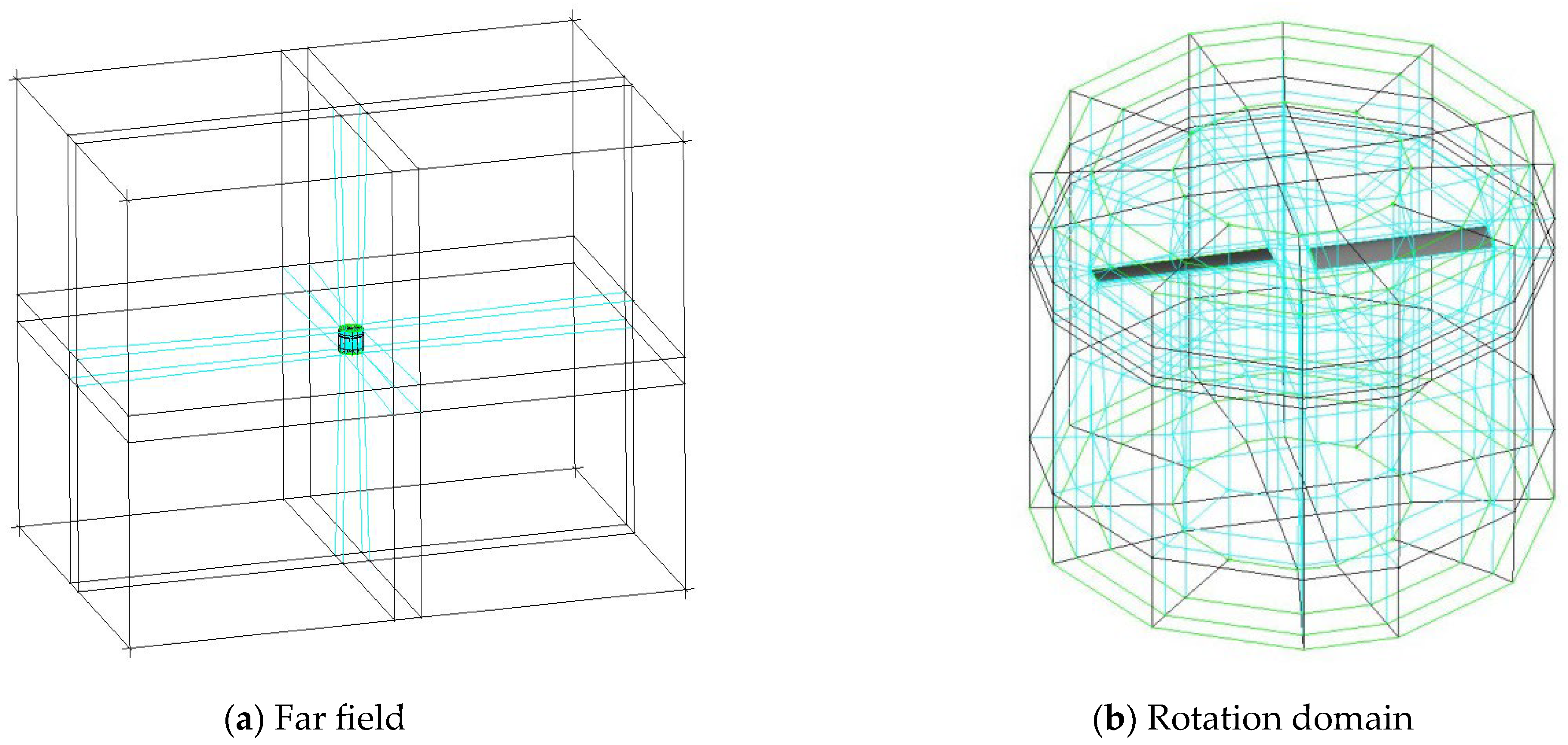
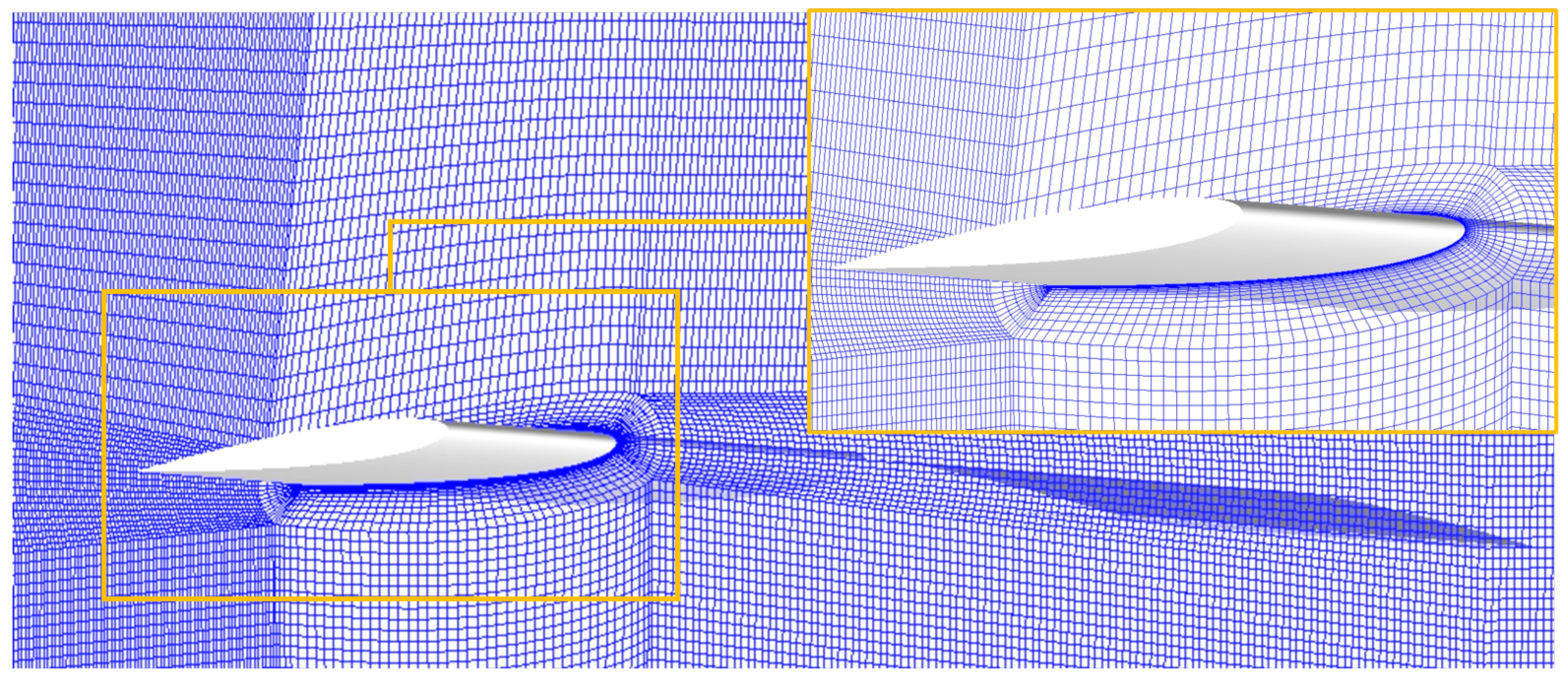
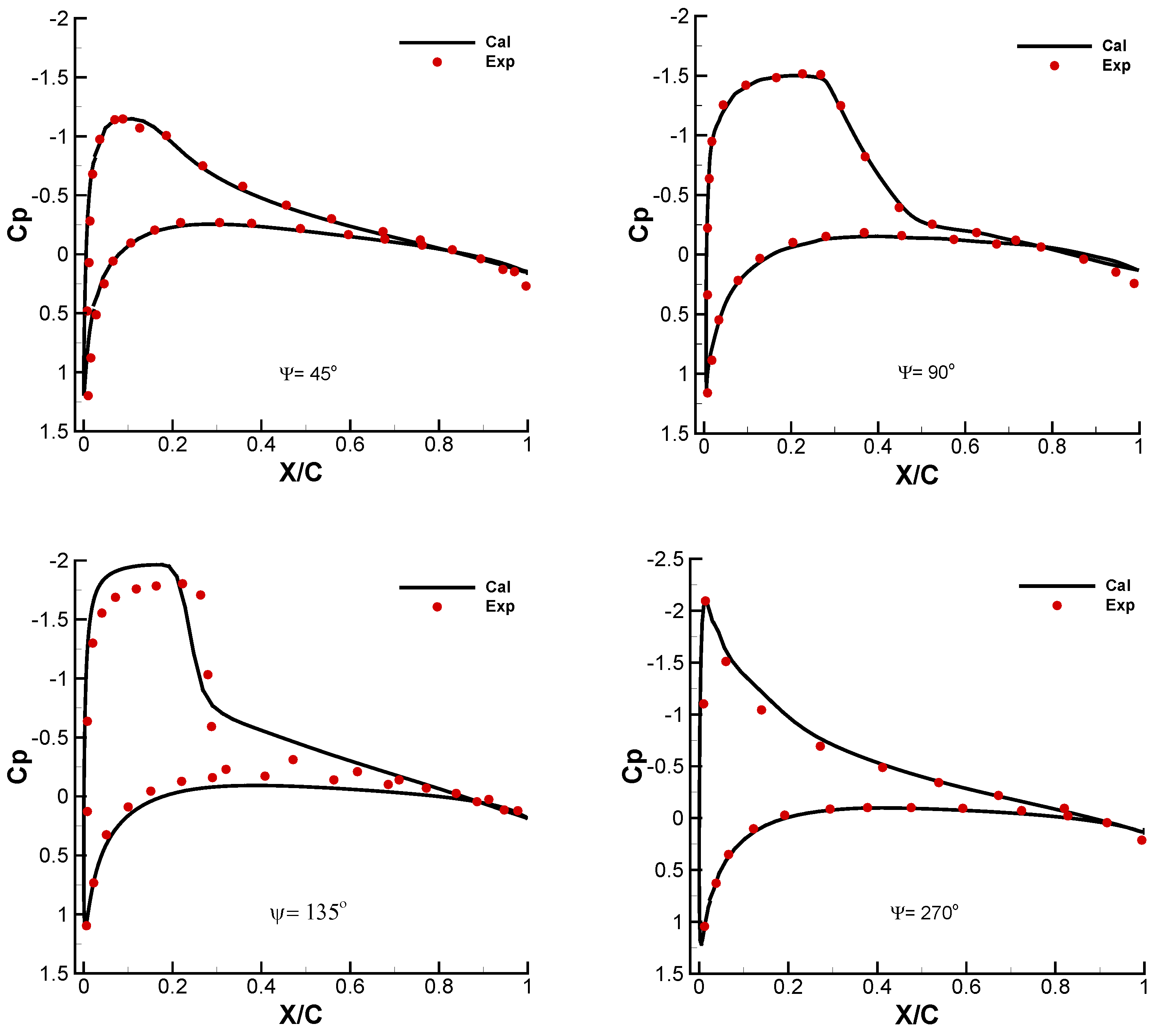
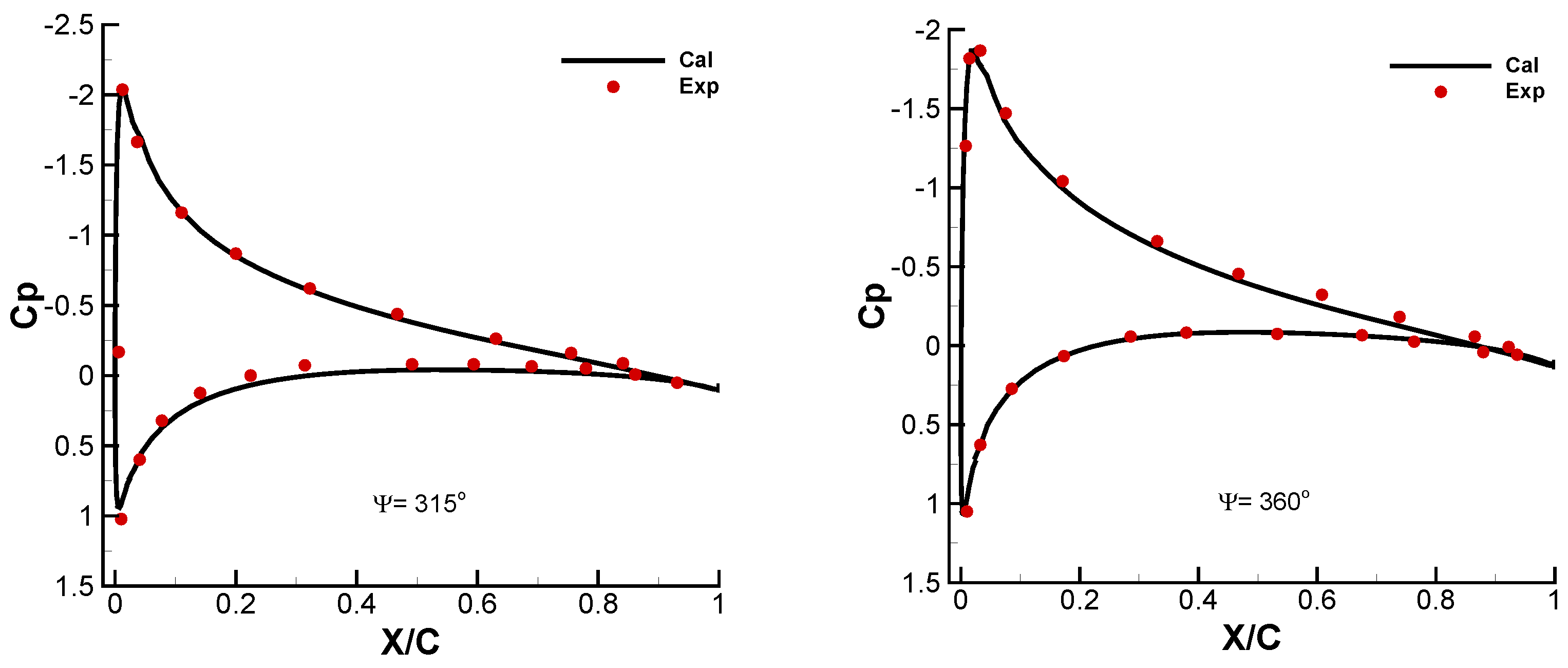
2. Methodology and Validation

This section presents the development and validation of the numerical method, which is established to handle blade rotation problems. Under the framework of an in-house code based on the finite volume method, the third-order scheme of MUSCL–Roe [16] is implemented first for the spatial discretization of the convective fluxes, and then the viscous fluxes are discretized with the second-order central differences. The dual-time approach based on the fully implicit LU–SGS method [17] is implemented as the time-marching method. The effect of turbulence is estimated using the Spalart–Allmaras one-equation model [18]. The reliability of the code has been verified via a series of works [19,20].
The feasibility of the numerical method for the numerical investigation is verified through the case of a two-bladed Caradonna–Tung rotor under the forward flight condition [21]. The purpose of the test is to obtain the pressure distribution and aerodynamic load on the rotor surface. The radius of the rotor is 1.143 m and the aspect ratio of the blade is 6. The cross-sectional shape is the NACA0012 airfoil. Pressure sensors are installed on two blades in the same radial positions.
The ICEM–Hexa is applied in the generation of a multi-block structured grid. The O-topology is applied to describe the rotation flow field. The grid topology of the rotor is shown in Figure 1. For the numerical simulation issues with relative motions, the dynamic patched grid is used [22,23], which has the primary advantage of handling relative motion. Based on this grid generation method, the grid of the helicopter and main rotor can be generated independently without considering the topology relation among adjacent blocks. Fluxes are interpolated through the patched surfaces, thus enabling the coupling of the flow information of adjacent subdomains. For the purpose of improving the prediction accuracy of the rotor wake vortex and flow field, the grid in the region below the rotor is refined. The first cell height near the wall is set at 1 × 10⁻⁶ R to ensure y+ ≈ 1, and the complete grid consists of 10,489,523 nodes. Figure 2 demonstrates the spatial grid of the blades and the grid used for the boundary layer profile.
The numerical simulation is performed for the forward flight case, corresponding to the conditions shown in Table 1. In the current study, the step size of the per physical time step is set at equivalent to ∆Ψ = 1.0 deg. The numerical simulation is carried out for 50 full revolutions first to provide a convergent flow field solution, then for 10 full revolutions to obtain a reliable solution, which is consistent with previous works [20]. The total numerical effort in CPU time is 200 h and the number of processors is 64.
Figure 3 shows the comparison between the calculated chordwise pressure distribution and the test result at the radial position r/R = 0.89 at several azimuth angles in one rotor revolution. It can be seen that the numerical results are in fairly good agreement with the experimental results at most azimuth angles. The pressure peak at the leading edge of the upper surface of the blade and the subsequent pressure recovery process are predicted well. However, noticeable discrepancies can be seen at Ψ = 135 ° , mainly because the strength of the shock wave near the radial station is notable at this particular azimuth angle.
The isosurface of the Q-criterion is shown in Figure 4. The result shows that vortices induced by the blade tip extend helically backwards and interfere with each other in the forward flight case. The phenomenon of blade–vortex interference is also captured. A snapshot of the vorticity distribution on the symmetrical plane is shown in Figure 5. The blade tip vortex develops backwards with a gradual decrease in strength, which indicates that the tip vortex is gradually dissipating. In general, the numerical results confirm that the numerical approach can accurately reflect the aerodynamic performance of the rotor in forward flight, while the development and transformation of vortices can be predicted.

3. Analysis of Main Rotor Rotating Effects

In this section, a numerical investigation of the main rotor blade rotating effects is carried out based on a light civil helicopter configuration [19]. The flow fields of the rotor-off and rotor-on configurations are used to compare the discrepancies in the drag performance and flow field characteristics.

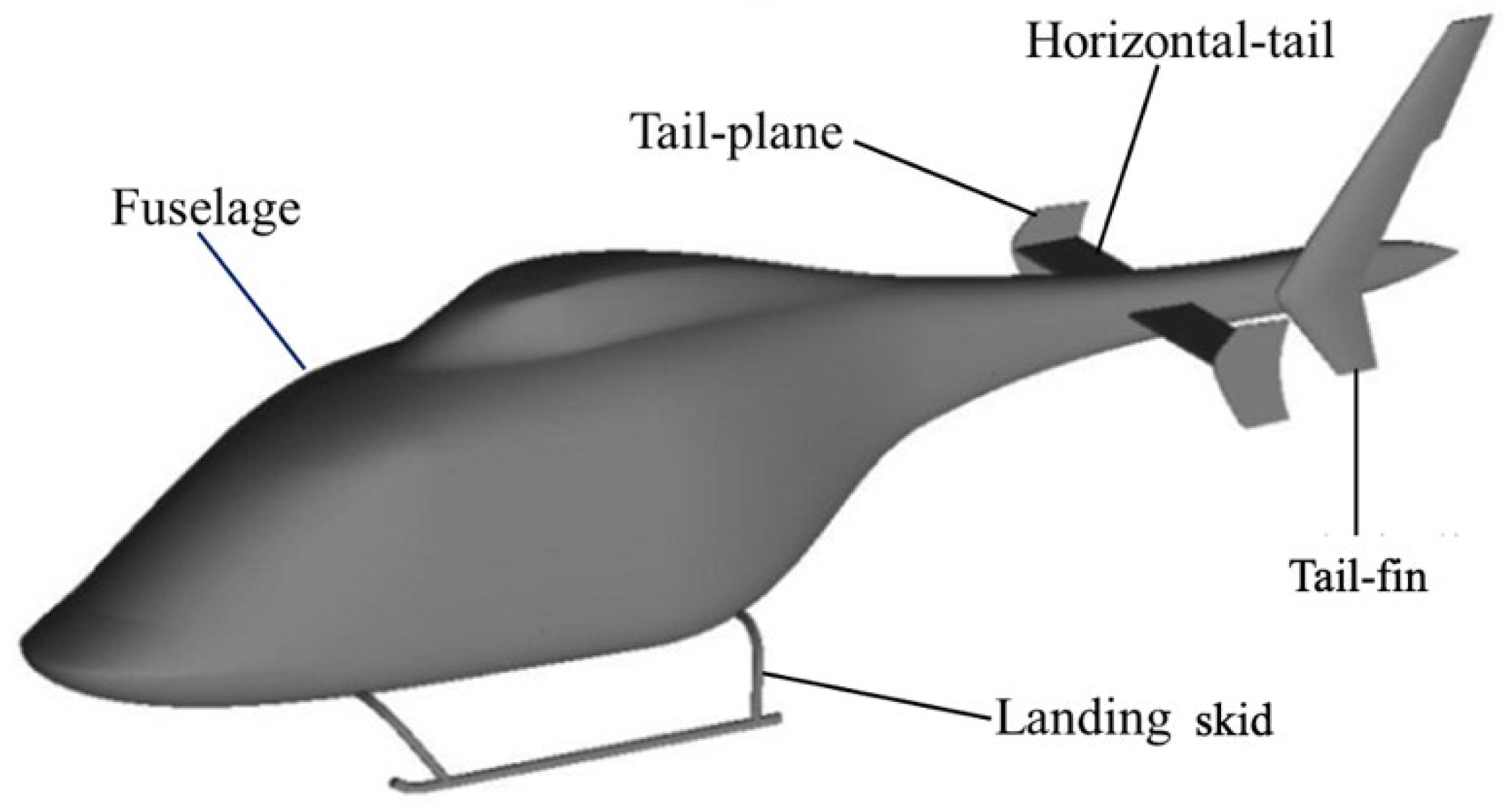
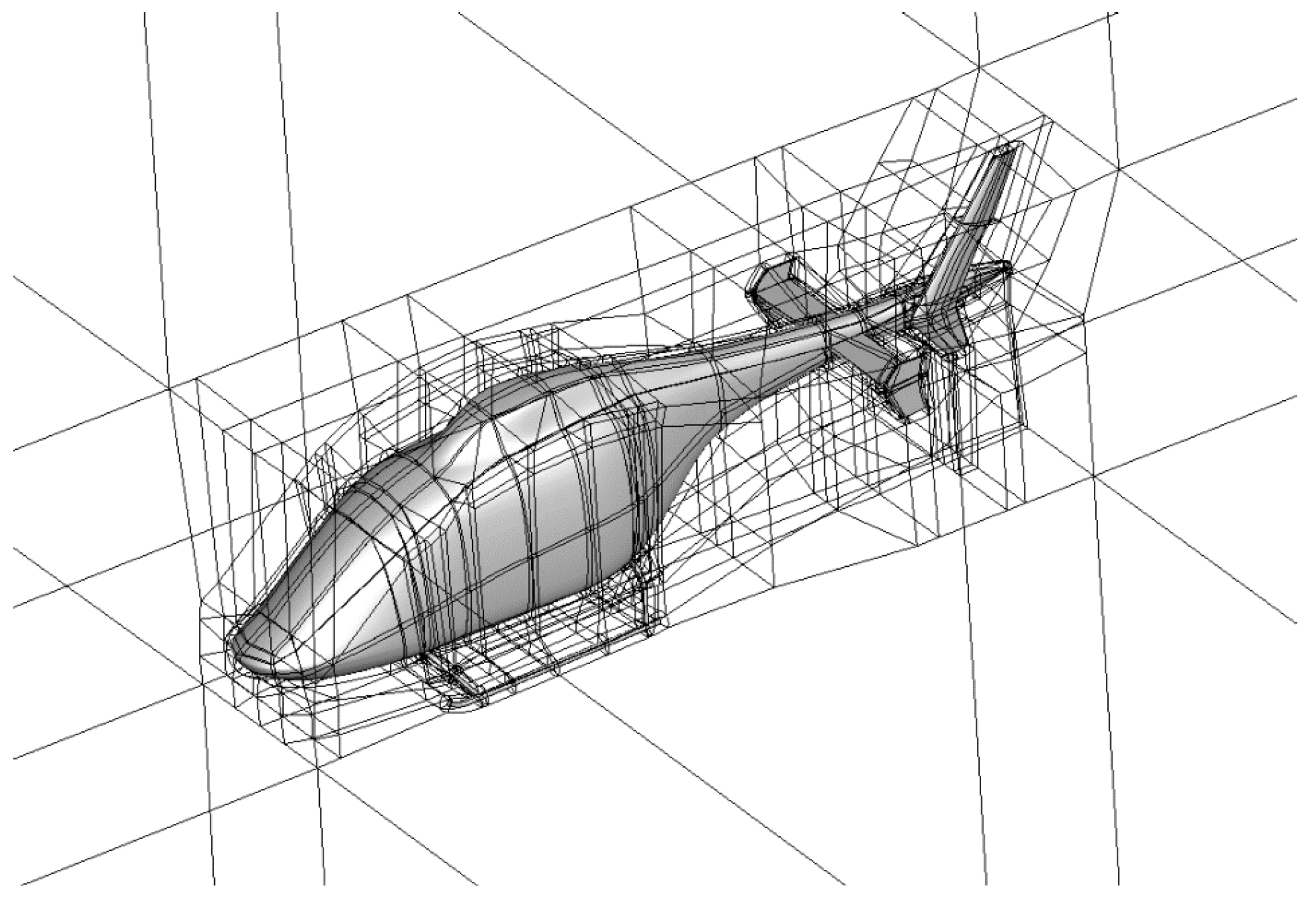
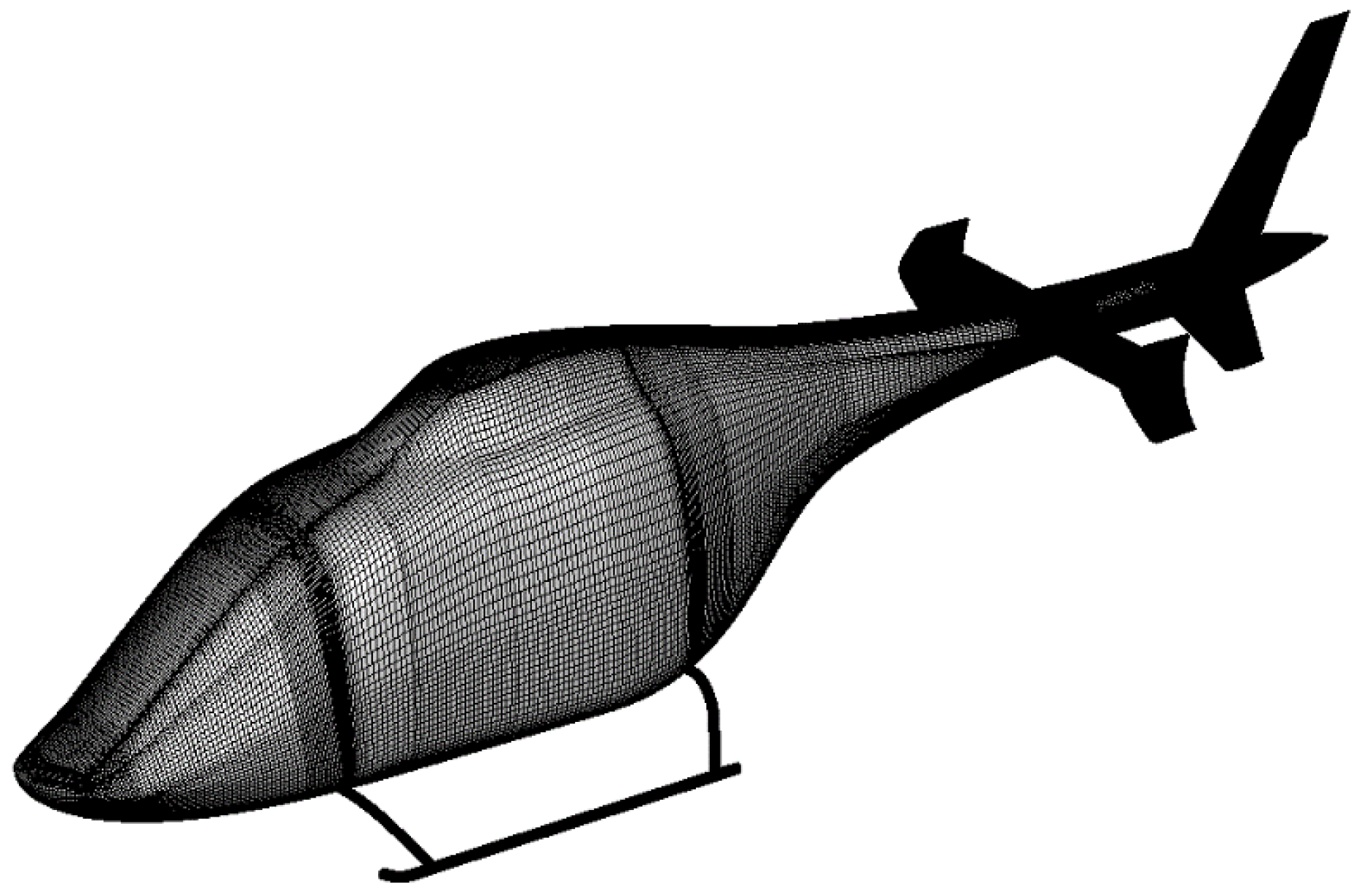
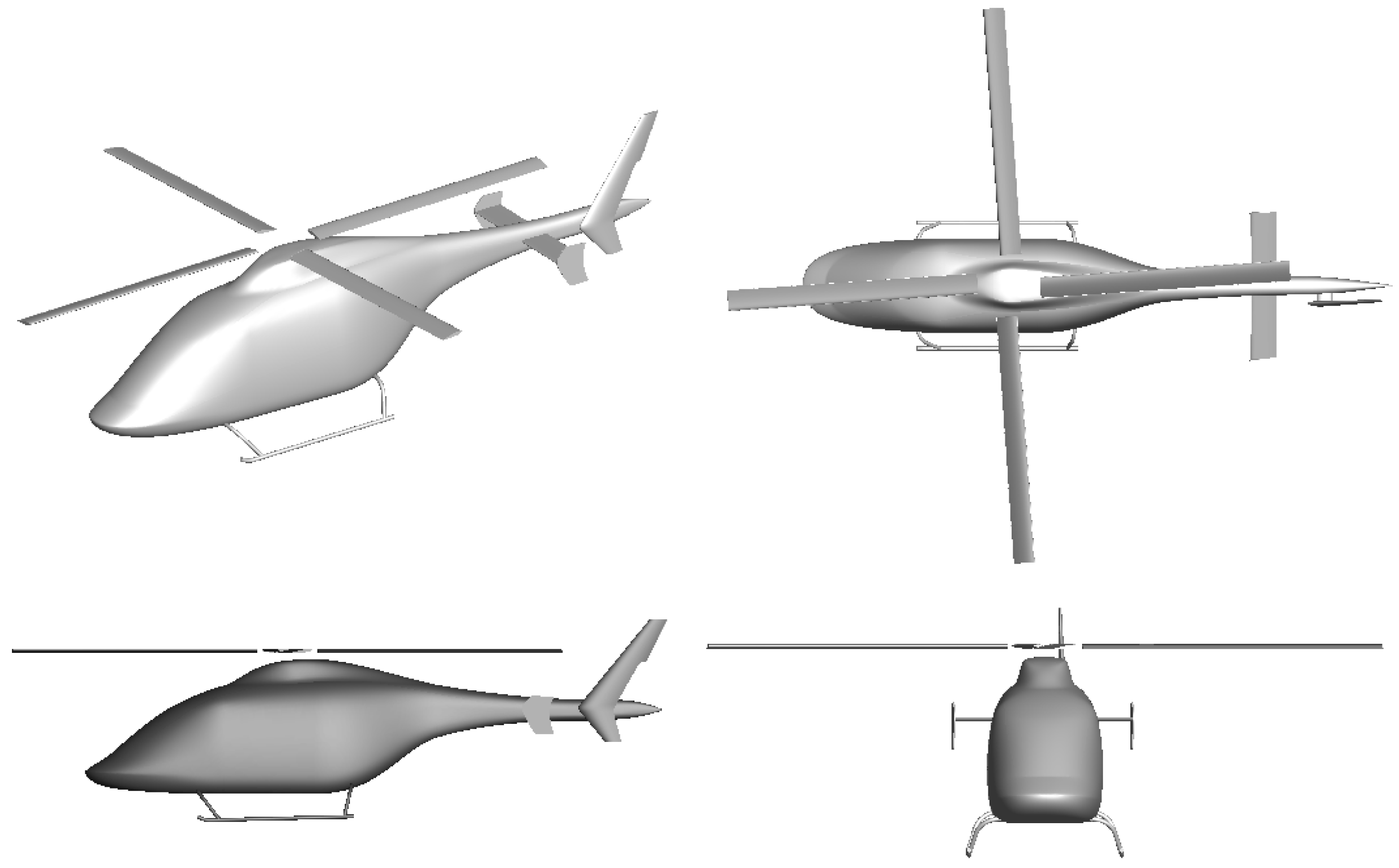
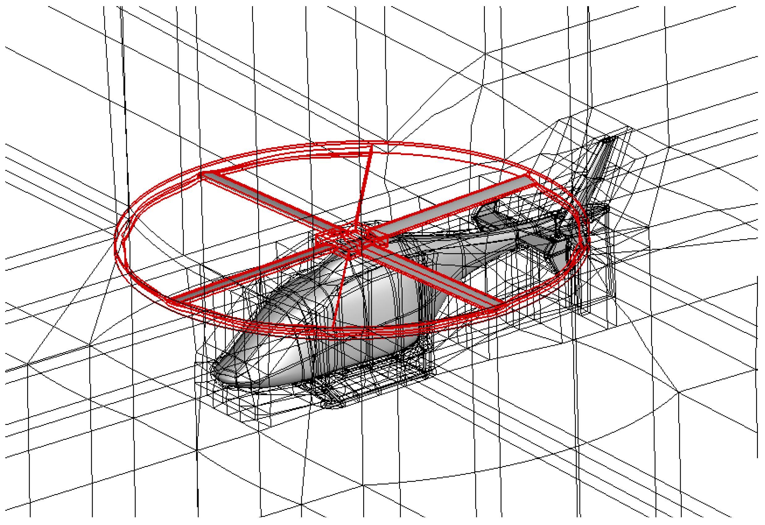
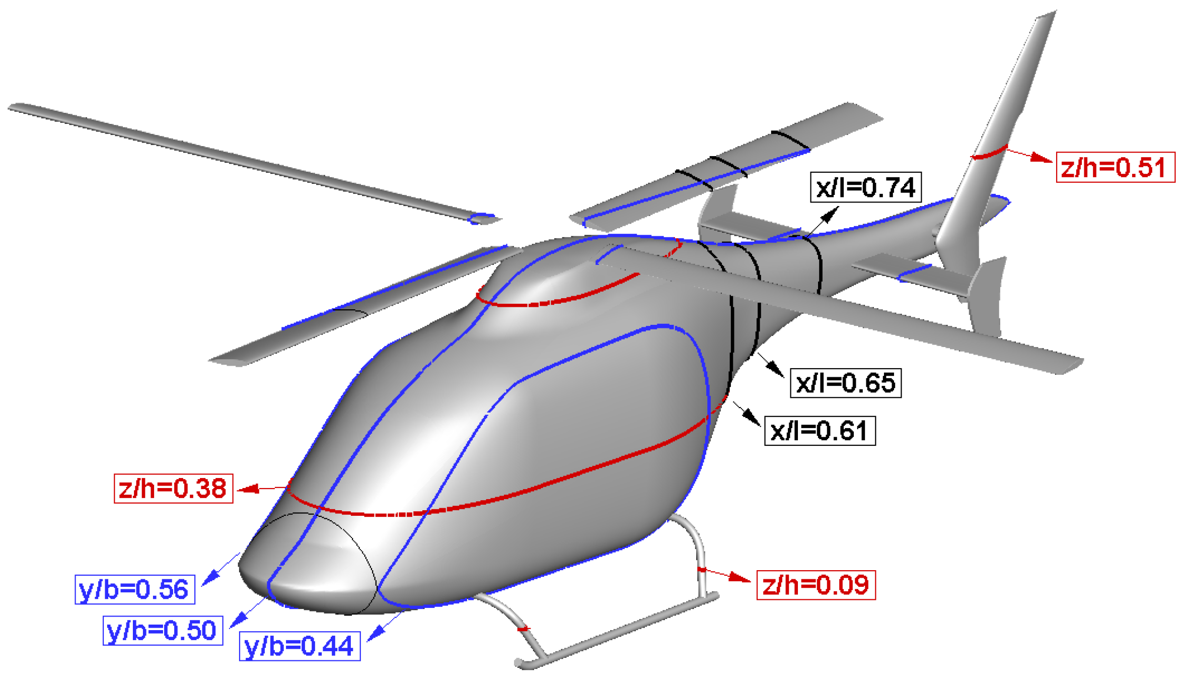
3.1. Configurations and Grid

The numerical investigation of the main rotor blade rotating effects is initiated with the calculation of the rotor-off configuration as shown in Figure 6, with a fuselage of 11 m used as the reference length for the aerodynamic coefficient. The length of the landing skids is 28.6% of the fuselage length with circular cross-sections. The horizontal tail is located at the position of 76% of the total fuselage length, while the vertical tail is installed at 87.3% of the total length. The H-topology is used with the O-topology around the configuration in order to describe the viscosity effects of the boundary layer. The height of the first layer near the wall is installed as a 10−5 reference length so as to obtain a small y+ ≈ 1. The complete grid consists of 19,082,201 nodes. Figure 7 and Figure 8 show the grid topology and surface grid of the configuration. The rotor-off configuration is simulated under the forward flight condition as listed in Table 2.
The model of the rotor-on configuration with the four-bladed main rotor with a radius of 5.5 m and a chord length of 0.42 m is given in Figure 9. It is necessary to simplify the rotor-on configuration for the purpose of facilitating the numerical simulation and reducing the calculation time; therefore, the rotor hub, hub fairing and other components are removed to simplify the computational model. This simplification will cause a significant reduction in the difficulty of grid generation. It should be noted that the main rotor rotates in a counterclockwise direction as seen from above. The computational grid for the current model can be considered as the combination of the main rotor domains and fuselage domains with the application of dynamic patched-grid technology. To improve the resolution in the wake area, the grid beneath and behind the main rotor is refined. The complete grid consists of 55,106,281 total nodes. The grid topology and surface grid of the rotor-on configuration are presented in Figure 10 and Figure 11.

3.2. Drag Performance
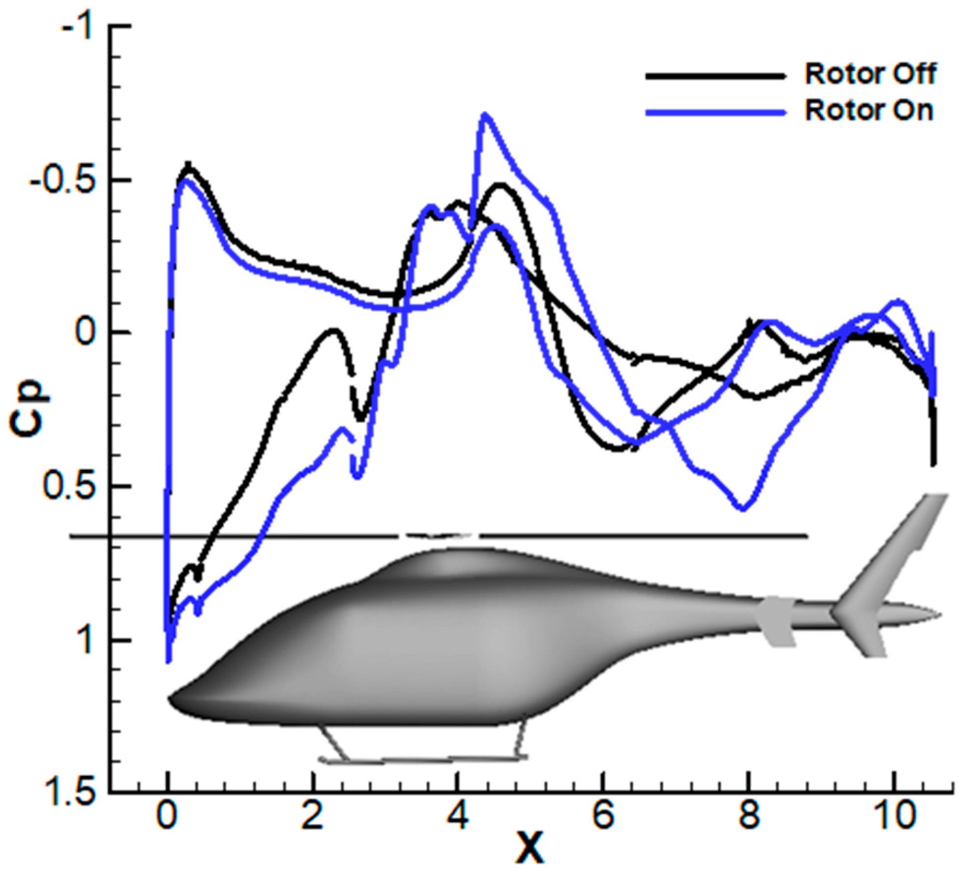
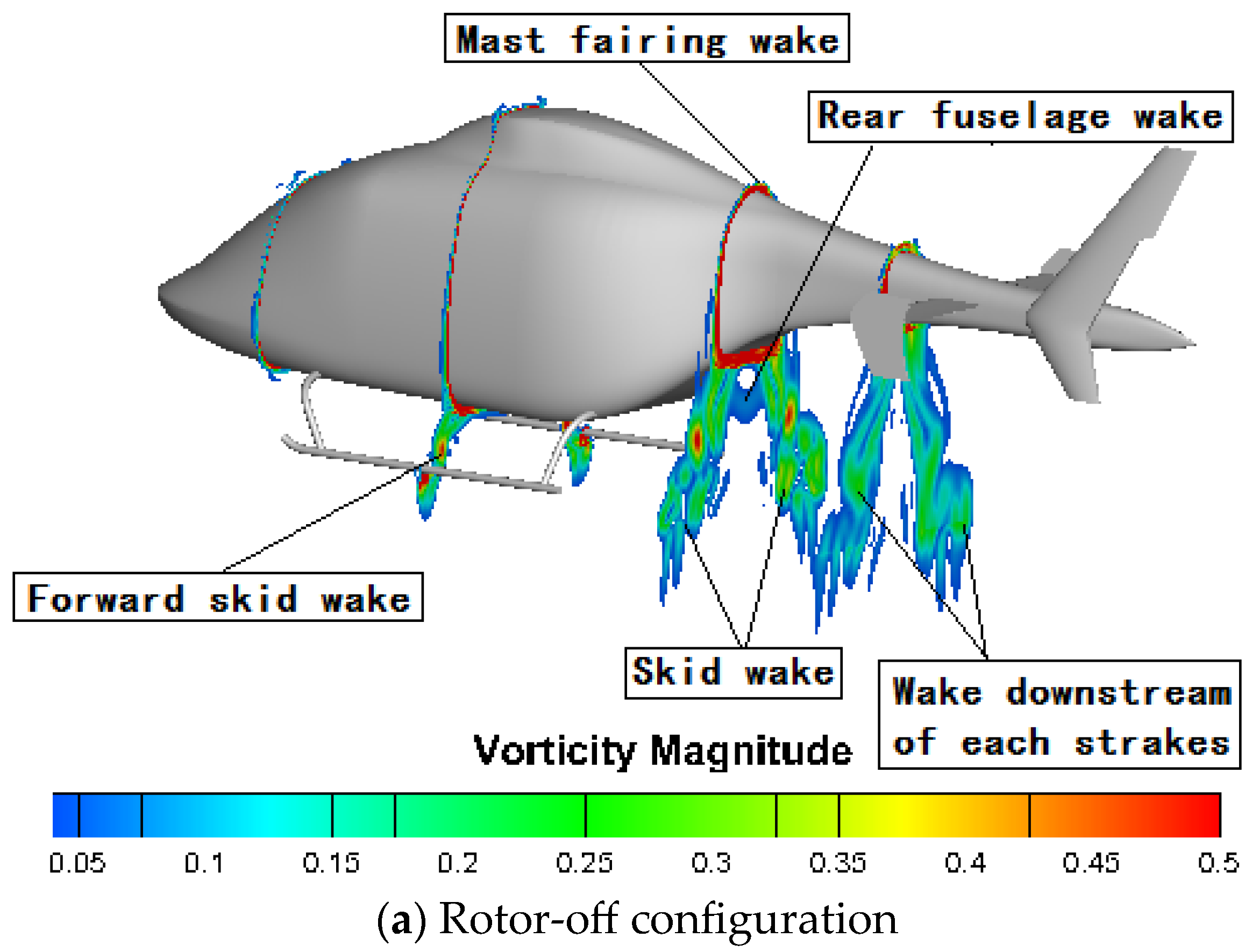
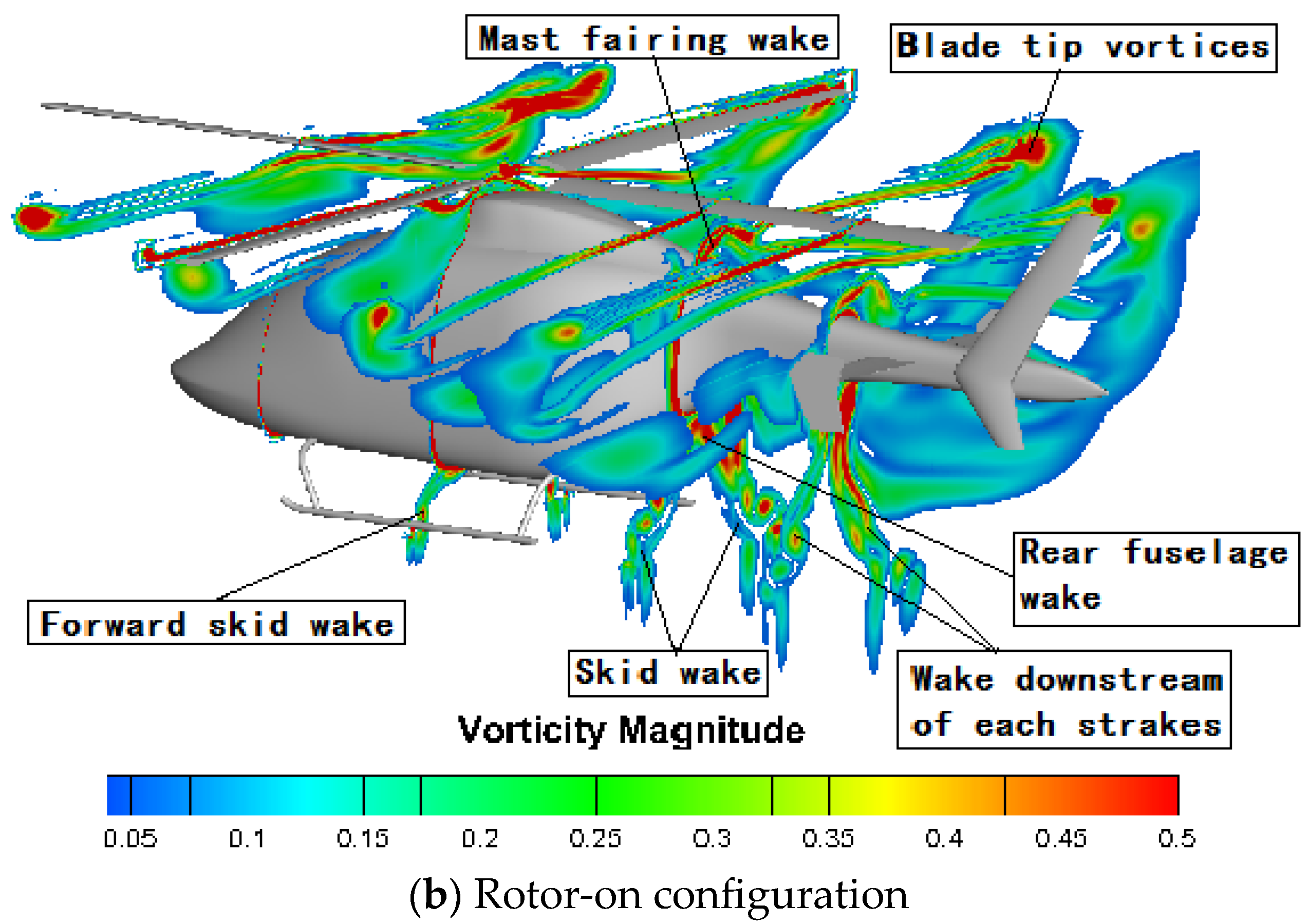
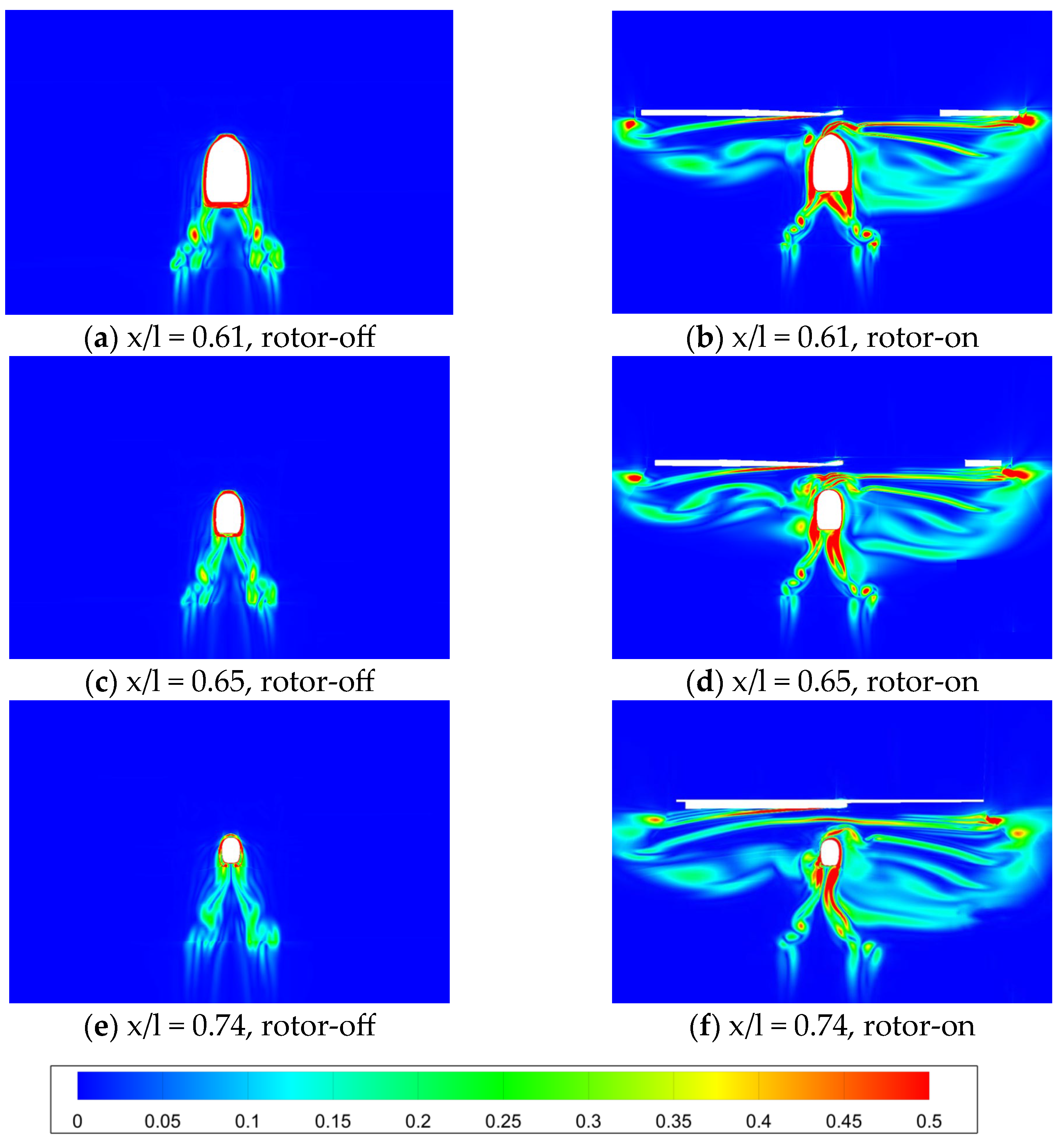
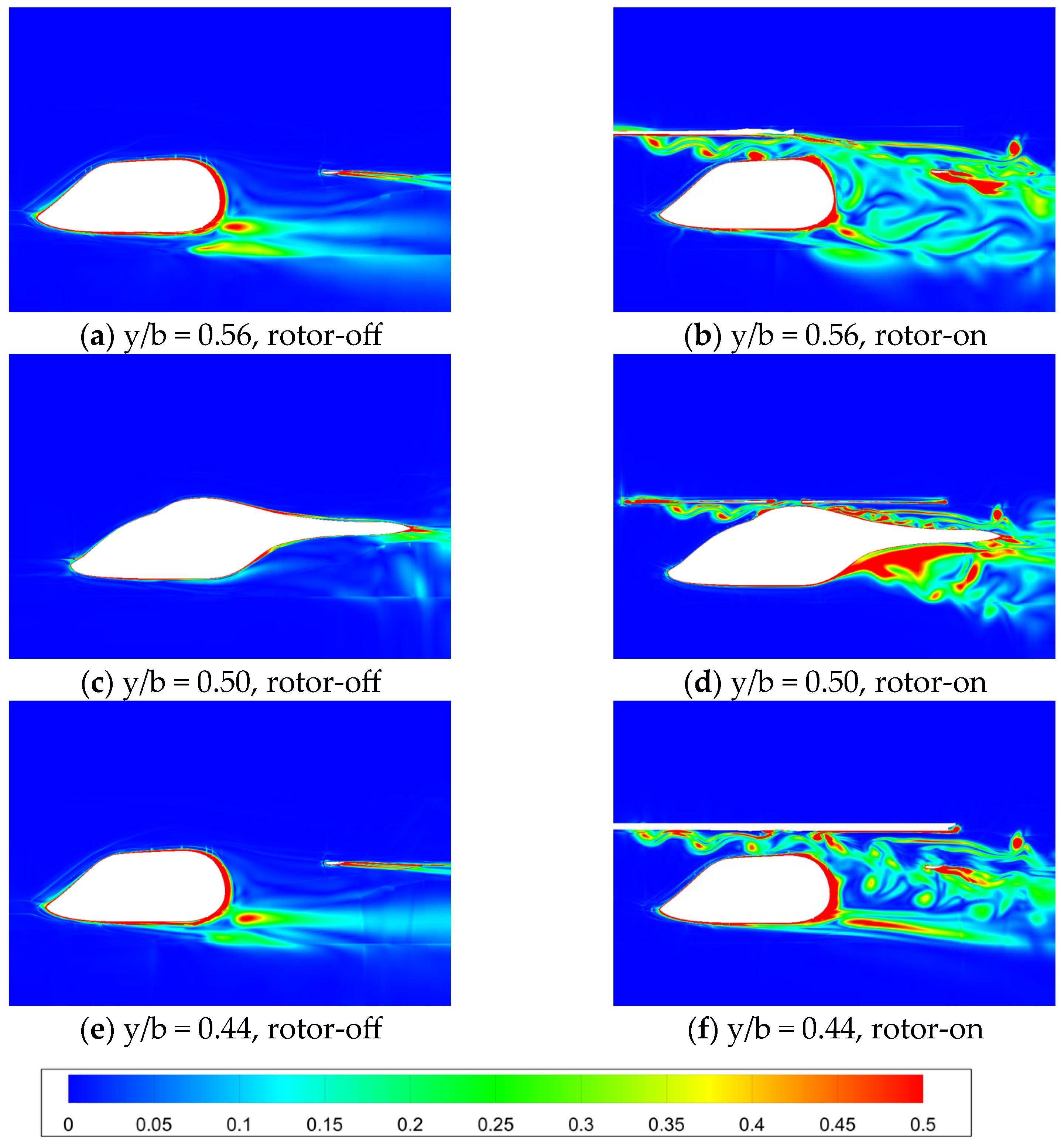
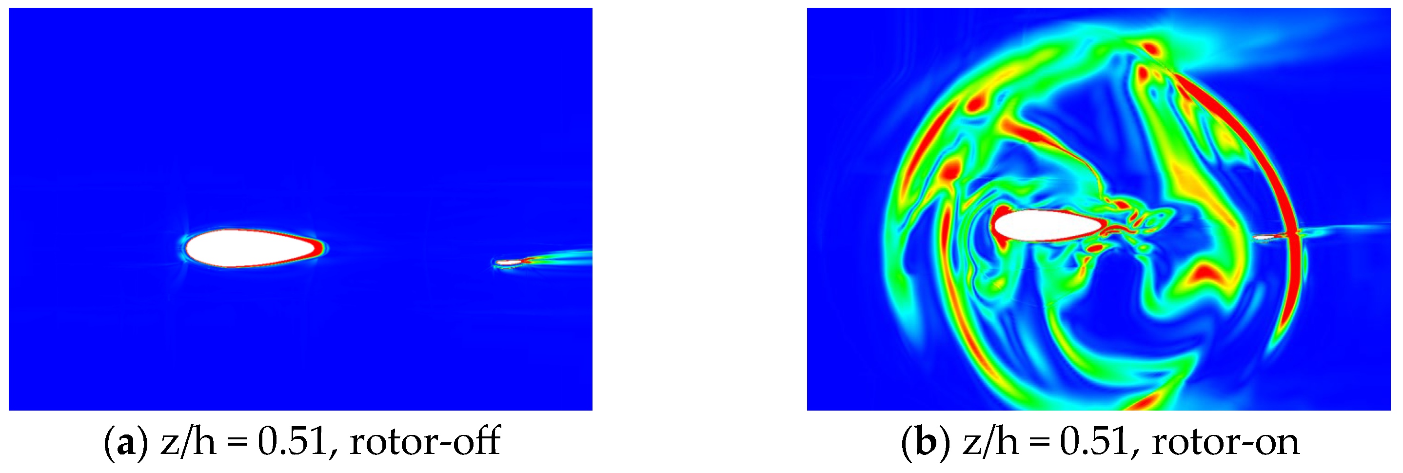
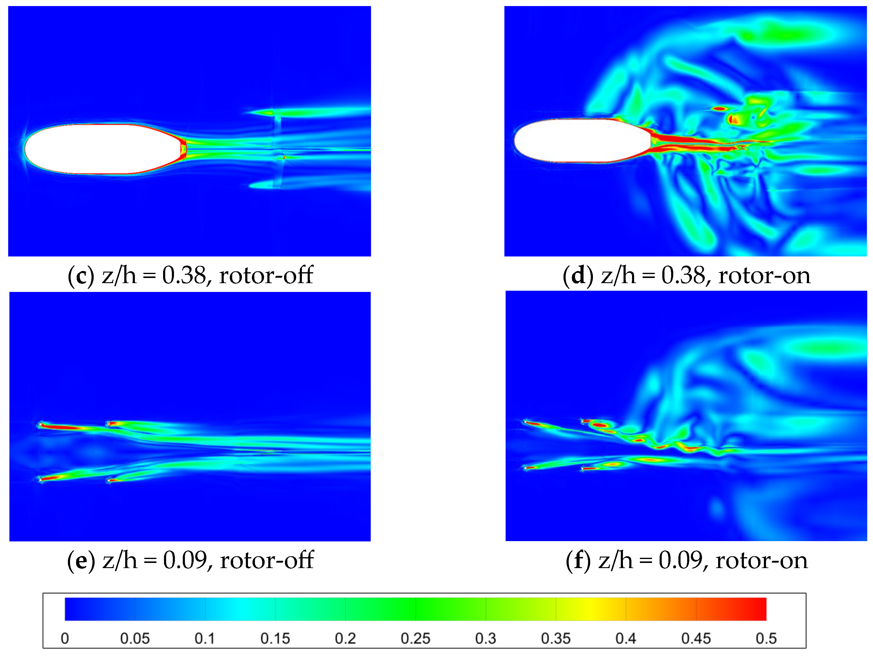
The simulation is carried out under the forward flight condition as listed in Table 2 as a typical forward flight case of α = 8 ° . The physical time step size is set at φ = 0.25 ° . Similarly, the calculation of the rotor-on case is carried out for 50 full revolutions first to provide convergence, then for 10 full revolutions to obtain a reliable solution. The total numerical effort in CPU time is 480 h and the number of processors is 64.
To investigate the drag performance of each component, the configuration is decomposed into several parts, including the fuselage, horizontal tail, left tail plane, right tail plane, landing skid and vertical tail. Table 3 compares the C D of the different components of the two cases at α = 8 ° , which reveals that the total C D increases by 0.102 (or 57.9%). Further observation shows that the C D of the fuselage increases by 0.098, which contributes to the main increment. The C D of the horizontal tail and vertical tail increase by 0.014 and 0.006, respectively. The C D of the left tail plane increases by 0.004, while the C D of the right tail plane decreases by 0.004, which cancel each other out. Notably, the C D of the landing skid is reduced by 0.016.
Figure 12 shows the comparison of the surface pressure distribution and streamlines between the rotor-off and rotor-on configurations, where the azimuth position of the blade is Ψ = 0 ° . From Figure 12a,b, it can be seen that the pressure on the afterbody and forehead of the rotor-on configuration increases due to the downwash of the main rotor, meaning an obvious low-pressure area on the left side of the cockpit can be observed. Low-pressure areas also appear on the left side and the upper surface of the fuselage. The pressure on the upper surface of the tail boom and the horizontal tail, together with the inner side of the tail plane, significantly increases. The streamlines on the rotor-off configuration distribute smoothly along the surface, while the streamlines on the tail boom of the rotor-off configuration obviously bend downward and backward, passing over the horizontal tail. From Figure 12c,d, a low-pressure region appears on the bottom surface of the horizontal tail for the rotor-on configuration, and the significant asymmetry of the pressure distribution can be observed. Due to the rotor wake induced by the advancing blade passing over the left tail plane, the rotor wake interferes with the bottom surface of the horizontal tail, resulting in the asymmetry of the pressure distribution. From the comparison of the surface pressure distribution in the symmetry plane of Figure 13, the source of the drag increase under the rotor-on condition is demonstrated clearly as the after body, where a large gradient of local pressure is observed.
The C D of the rotor-on configuration in one full rotor rotation is shown in Figure 14. A periodic fluctuation is observed, which indicates the aerodynamic interactions between the main rotor and the fuselage. Since the main rotor consists of four blades, the fluctuation in the C D can be considered as a period of Ψ = 90 ° . In one fluctuation period, the C D reaches the lowest value at the blade azimuth angle of Ψ = 18 ° , then the C D gradually increases with the azimuth angle, reaching a peak at Ψ = 72 ° . The change in amplitude of the C D is around ±20% in one period. The C D of each component at four azimuth angles during a period of rotation are summarized in Table 4.
Figure 15 shows instant snapshots of the pressure distribution at several azimuth angles. At Ψ = 0 ° , a large area of high pressure occurs on the forehead of the fuselage due to the interference of the blade and fuselage when the blade sweeps over, thus the pressure drag is large under this condition. The C D of the whole fuselage at Ψ = 25 ° decreases significantly compared with that of the fuselage at Ψ = 0 ° . At Ψ = 45 ° , the C D of the fuselage and horizontal tail increase. For 25° and 45°, the pressure drop on the upper surface of the forehead can be clearly seen in the figure, leading to a decrease in the fuselage pressure drag.
In the case of an azimuth of 70°, the C D of the fuselage and horizontal tail rises to 0.185 and 0.041, respectively. Then, the pressure on the nose of the fuselage increases again, while the pressure on the upper surface of the horizontal tail does not increase significantly. As given in Table 4, the blade azimuth angle is changing constantly, although the C D of the left and right tail planes, skids and vertical tail of the helicopter do not change much. It can be concluded that the change in the azimuth angle mainly affects the drag of the fuselage and the horizontal tail. Additionally, the pressure distribution indicates that the bottom surface of the fuselage is less interfered with by the unsteady effect, while the bottom surface of the tail boom and the surface of the nose are affected by the rotating flow, which varies slightly with the change in the blade azimuth angle. Due to the counterclockwise rotation of the rotor, the wake generated by the rotor firstly sweeps through the left tail plane, then passes through the horizontal tail, and finally passes through the right tail plane; thus, the total drag increment of the two tail planes is zero in one period.

3.3. Flow Field

To identify the general flow features caused by the rotation of the main rotor, the flow fields of the rotor-off and rotor-on configurations are examined, where the azimuth position of the blade is Ψ = 0°. Figure 16 shows the flow fields in the Q-criterion [24] and the streamlines of the two configurations, which are characterized by the Mach numbers. From Figure 16a, the flow of the afterbody of the fuselage is attached in general, while a vortices system is generated backward at the junction of the fuselage and landing skid. The vortices system interferes with the components of the rear fuselage and affects the aerodynamic performance of the horizontal tail. Simultaneously, the pillars induce the wake of the skid, while the horizontal tail and other components also generate vortices that develop toward the rear fuselage. In Figure 16b, the blade tip vortices pulled out by the main rotor are developing downward and backward. The wake vortex from the tip and root of each blade forms a complex vortices system. The rotor wake sweeps along the fuselage and affects the flow field near the fuselage and other components. The flow field of the upper surface of the fuselage becomes more complicated due to the interference of the rotor wake in the vortices induced by the fixed components.
However, the structures of the vortices at the junction of the fuselage/landing skid are kept unchanged as the rotor wake mainly develops backward. The influence of the rotor wake on the vortices system mainly manifests in a change in the wake flow direction, namely, the lateral deflection of the wake system. In addition, it seems that the strength of the wake is weakened by the existence of blade tip vortices, especially for the front pillars, which contributes to the decrease in the landing skid drag.
The vorticity distribution of the two configurations along the X-axis is plotted in Figure 17. Figure 17a depicts that the vorticity magnitude of the forward skid wake is large in the vicinity of the fuselage and at the bottom of the skid. As the skid wake develops to the rear fuselage, an obvious vorticity magnitude can still be observed. At this time, the vorticity magnitude of the rear fuselage wake is low at the rear fuselage, indicating that the flow separates there due to the interference between the downward skid wake and the rear fuselage wake. Similarly, the vorticity magnitude of the wake downstream of each strake gradually decreases, while the vorticity magnitude near the top fuselage is large. From Figure 17b, the vorticity distribution of the rotor-on configuration illustrates that the vorticity of the advancing rotor blade is greater than that of the retreating blade. By this time, the vorticity magnitude at the top of the fuselage is larger than the vorticity shown in Figure 17a, which is caused by the blade tip vortices and can be regarded as an important source of drag increment. As the wake vortex generated by the rotor develops downward and backward, the vorticity distribution of the skid wake, the rear fuselage and the downstream wake demonstrate significant changes.
The vorticity distributions at various sections aligned in the direction of the X-, Y- and Z-axis are plotted for comparative analysis, as shown in Figure 18. Here, the development of the rotor and fuselage wake in the flow field can be demonstrated. The study of the vorticity distribution along the X-axis focuses on the flow structure at the rear fuselage, while the study of the vorticity distributions aligned in the directions of the Y- and Z-axis focuses primarily on the effect of the rotor.
Figure 19 further depicts the plots of the vorticity distribution of the afterbody aligned in the direction of the X-axis. From Figure 19b,d,f, in the process of the development of the rotor wake, the strength of the blade tip vortices gradually decreases, indicating that the blade tip vortices are dissipating. It can also be noted that the flow field velocity gradient changes drastically on the blade-advancing side, while the velocity gradient endures less changes on the blade-retreating side. As also shown in Figure 19b,d,f, the vorticity magnitude at the fuselage top gradually decreases, indicating the gradual dissipation of the wake vortex with the development of the flow field. The comparison of the vorticity plots between the rotor-off and rotor-on configurations illustrates that the rotor wake interferes with the skid wake in forward flight. The vorticity distribution of the rotor-off configuration along the fuselage mid-plane is basically symmetrical, while the vorticity distribution of the rotor-on configuration shows obvious asymmetry. As the cross-sections of the tail boom become smaller at the rear part of the fuselage, the blocking effect on the rotating flow is reduced, meaning the mutual interactions and flow fusion between the rotor wake and the flow near the fuselage and the skid are enhanced.
Figure 20a,b plot the vorticity aligned in the direction of the Y-axis, where an increase in the vorticity magnitude beneath the plane of rotation can be observed. In Figure 20b, the rotor rotation induces an additional afterbody vortices system. Figure 20c,d suggest that the vorticity magnitude of the afterbody increases significantly, indicating that strong flow interactions occur between the rotor wake and the fuselage wake. The strong vortices system will induce a large reverse pressure gradient on the rear part of the fuselage, which contributes to the increase in the pressure drag, a fact that is illustrated clearly in Table 3. Due to the rotor rotation direction, at the y/b = 0.56 and y/b = −0.44 positions shown in Figure 20b,f, different flow structures dominate, namely, the competition between the blade tip vortices system and the afterbody vortices system. In Figure 20b, the evolution of the blade tip vortices is restrained by the fuselage, while the interference between the two sets of vortices is obvious. In Figure 20f, the complete blade tip vortices spread backward, and the strength of the vortices decreases and dissipation occurs, while the influence region of the afterbody vortices is limited so that the vortices’ interference is weakened.
Figure 21 shows the plots of the vorticity magnitude in the direction of the Z-axis. The wake range induced by the rotor blade tip can be seen in Figure 21b, and the wake shifts backward and sweeps over the vertical tail, with a large vorticity magnitude at the blade tip. From Figure 21e, two strips with high vorticities are pulled out from the skid pillars, while the shear layer generated by the front skid pillars is relatively thin. From the vorticity plot of the rotor-on configuration, as shown in Figure 21f, the vorticity magnitude of the strips pulled out by the front skid pillars is reduced, thus the impact on the rear skid pillars of the separation vortices shedding periodically is released, resulting in a decrease in the pressure drag.

4. Conclusions

Based on dynamic patched-grid technology coupled with a three-dimensional N–S equation solver, the numerical study of the aerodynamic interaction effects between the rotor and fuselage on the drag performance and flow field of the fuselage of a light civil helicopter is carried out under the forward flight condition. The conclusions can be summarized as follows:
(1)
The comparison of the drag performance between the rotor-off and rotor-on configurations shows that the total drag increases by 57.9% while the drag of the fuselage and horizontal tail increases by 124.1%.
(2)
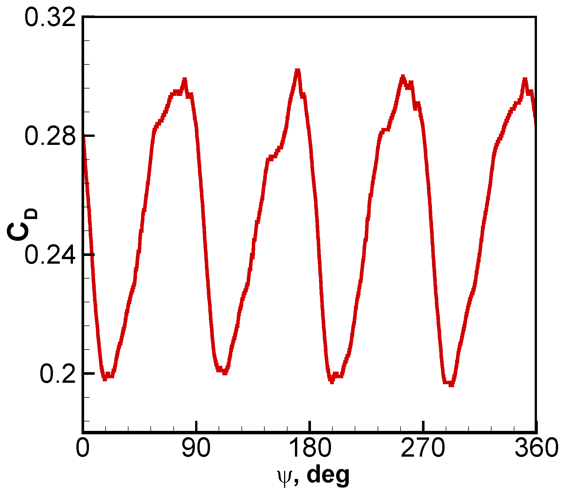
The cycle of the drag fluctuation is observed in one full revolution of the rotor with a change in amplitude of ±20%. The change in the azimuth angle of the rotor mainly affects the drag performance of the fuselage and horizontal tail.
(3)
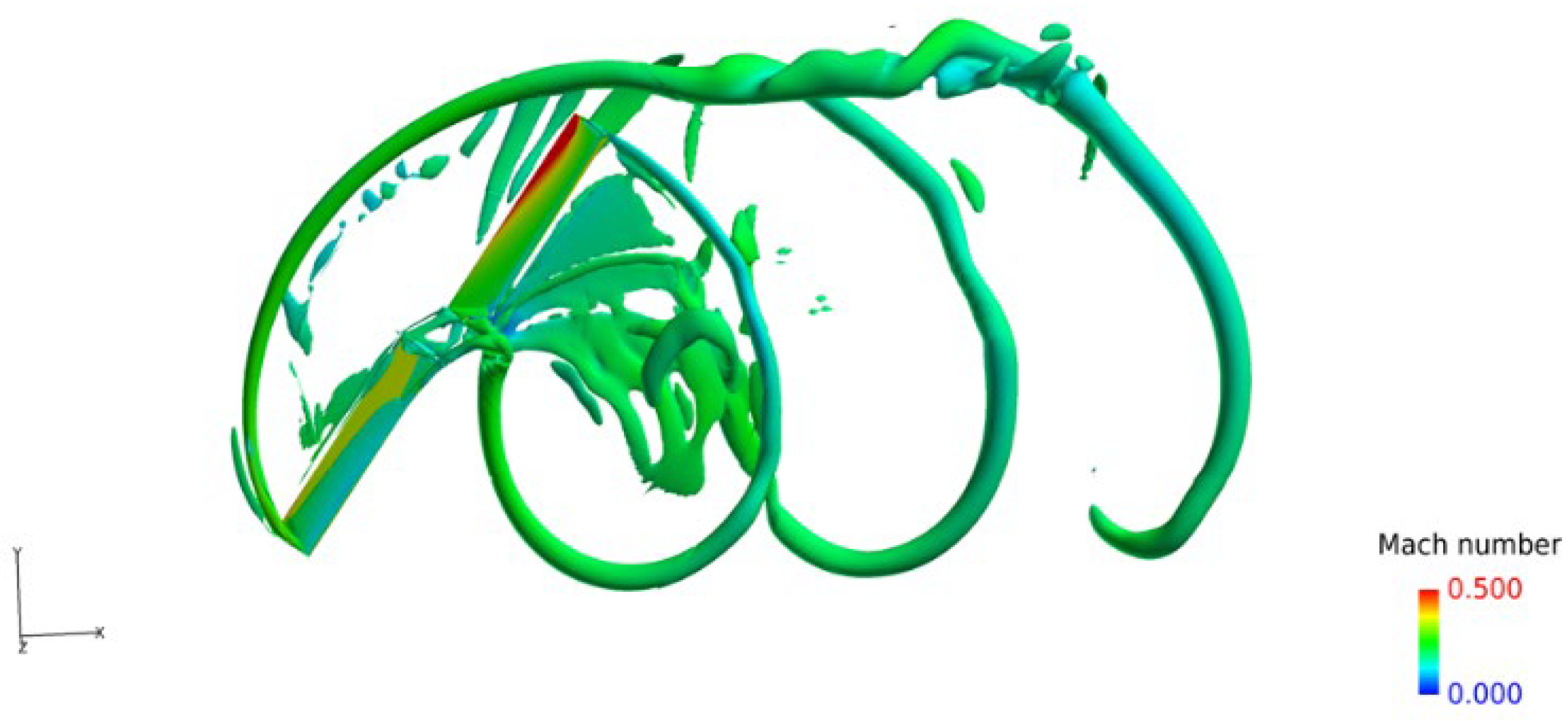
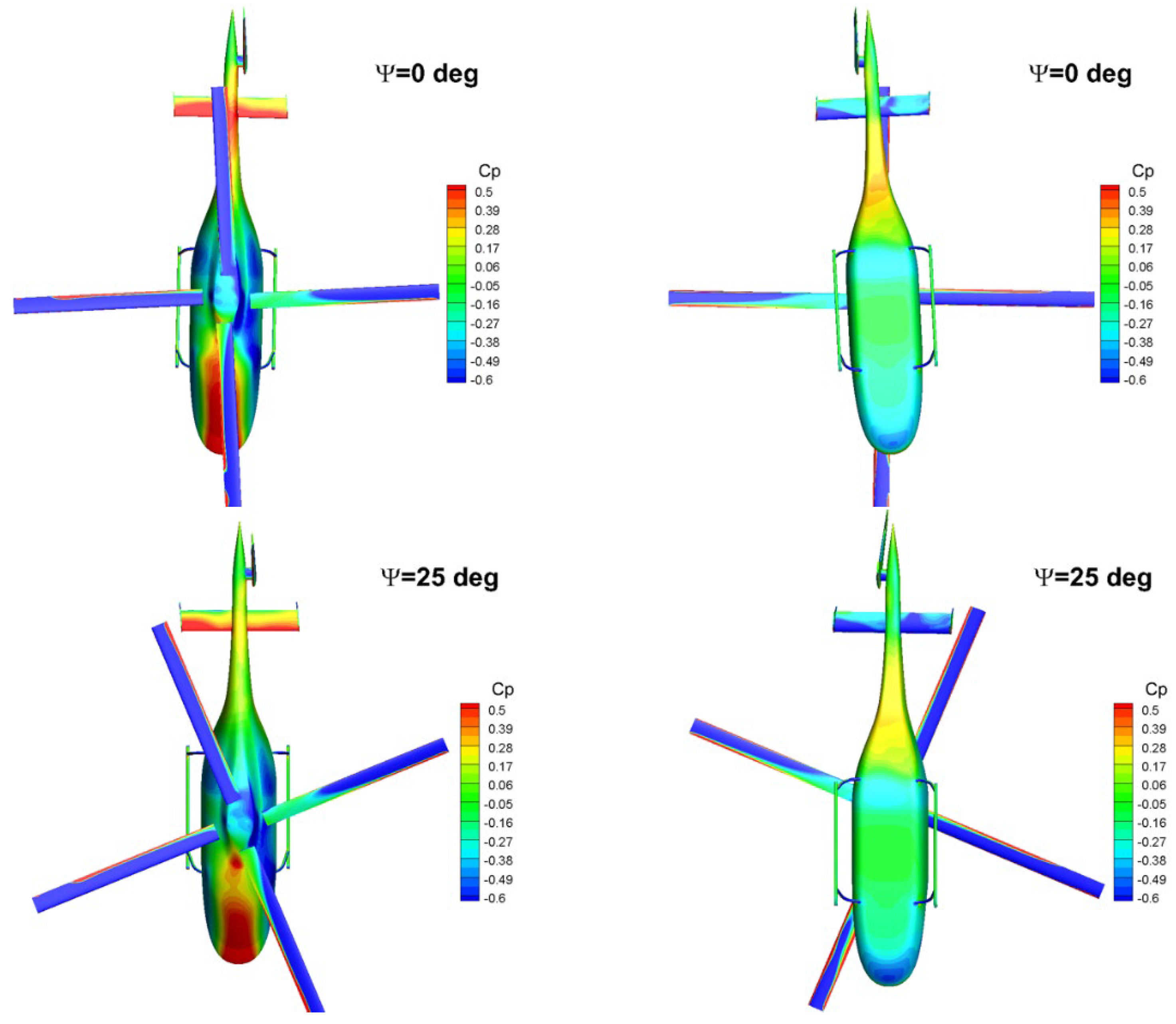
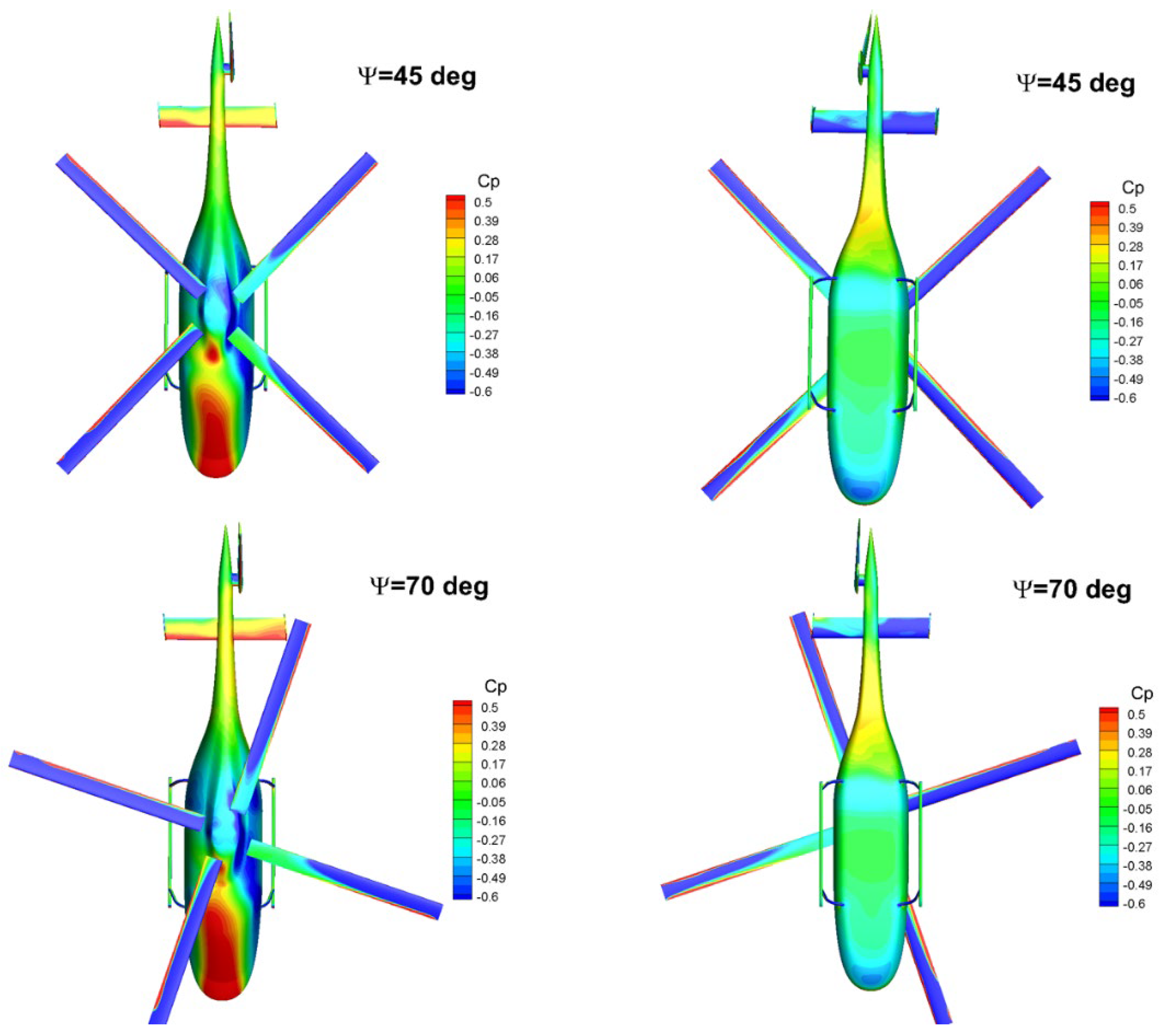
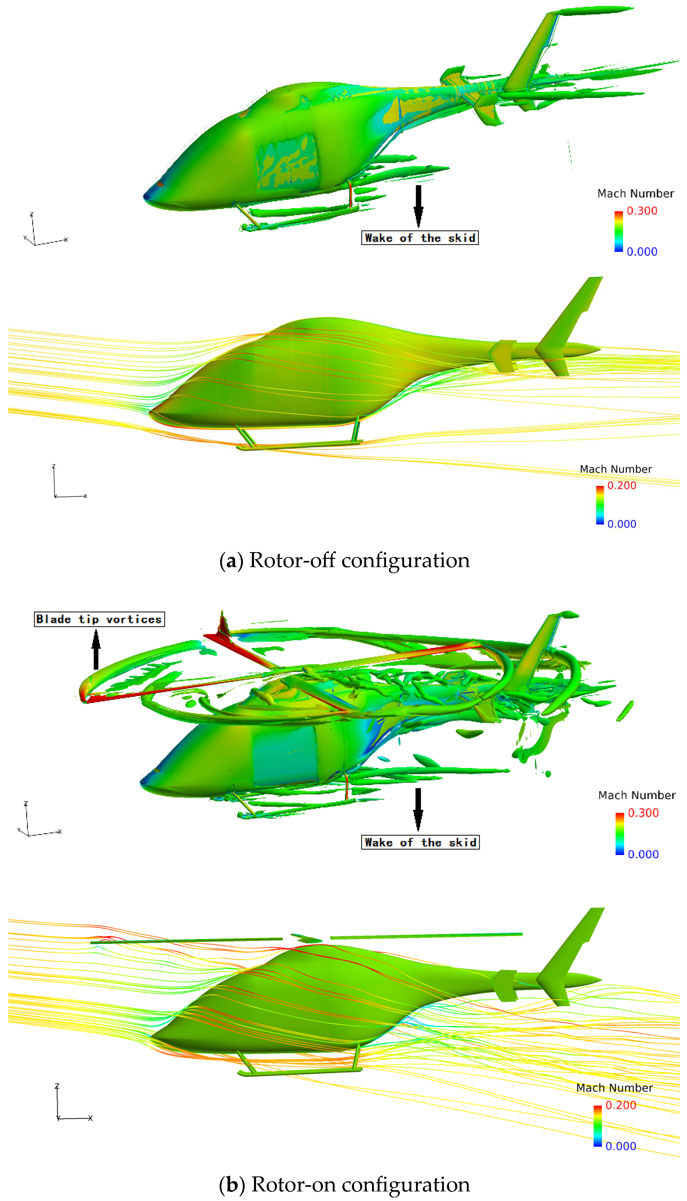
The aerodynamic interaction effects between the rotor and fuselage on the drag performance are mainly reflected in the influence of the backward-developing rotor wake on the flow field of the rear part of the fuselage. Rotor rotation induces an additional afterbody vortices system.
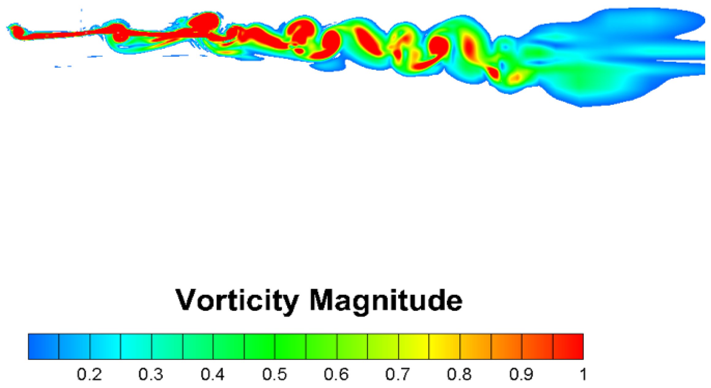
(4)
The vorticity magnitude of the rotor-on configuration near the rear fuselage/tail boom increases significantly, suggesting that strong flow interactions occur between the rotor wake and the fuselage wake, forming a vortices system with a wide range. This vortices system causes a large reverse pressure gradient on the rear surface of the fuselage, which contributes to the increase in the pressure drag.
Although the basic features of the aerodynamic interaction effects between the rotor and fuselage can be reflected by the RANS, which is an effective tool for the prediction of general performance, it should be pointed out that due to the turbulence being totally modeled and averaged, the time-dependent nature of the flow field cannot be considered precisely reflected; thus, the application of advanced turbulence simulation approaches such as the hybrid RANS/LES method is necessary in further studies.

Author Contributions

Conceptualization, H.Z.; methodology, W.S.; software, W.S.; validation, W.S.; formal analysis, W.S.; investigation, W.S.; resources, Y.L.; data curation, Y.L.; writing—original draft preparation, W.S. and Y.L.; writing—review and editing, H.Z.; visualization, Y.L.; supervision, H.Z. All authors have read and agreed to the published version of the manuscript.

Funding

This research was funded by Scientific Research Fund of Young Teachers in Xi’an Technological University.

Institutional Review Board Statement

Not applicable.

Informed Consent Statement

Not applicable.

Data Availability Statement

Data available on request due to restrictions of privacy.

Conflicts of Interest

The authors declare no conflict of interest.

References

  1. Conlisk, A.T. Modern helicopter rotor aerodynamics. Prog. Aerosp. Sci. 2001, 37, 419–476. [Google Scholar] [CrossRef]
  2. Stepanov, R.; Zherekhov, V.; Pakhov, V.; Mikhailov, S.; Garipov, A.; Yakubov, W.; Barakos, G.N. Experimental Study of Helicopter Fuselage Drag. J. Aircr. 2016, 53, 1343–1360. [Google Scholar] [CrossRef] [Green Version]
  3. Leishman, J.G.; Bi, N.-P. Aerodynamic Interactions between a Rotor and a Fuselage in Forward Flight. J. Am. Helicopter Soc. 1990, 35, 22–31. [Google Scholar] [CrossRef]
  4. Mavris, D.N.; Komerath, N.M.; McMahon, H.M. Prediction of Aerodynamic Rotor-fuselage Interactions in Forward Flight. J. Am. Helicopter Soc. 1989, 34, 37–46. [Google Scholar] [CrossRef]
  5. Zori, L.A.J.; Rajagopalan, R.G. Navier-Stokes Calculations of Rotor-fuselage Interaction in Forward Flight. J. Am. Helicopter Soc. 1995, 40, 57–67. [Google Scholar] [CrossRef]
  6. Batrakov, A.; Garipova, L.; Kusyumov, A.; Mikhailov, S.; Barakos, G. Computational Fluid Dynamics Modeling of Helicopter Fuselage Drag. J. Aircr. 2015, 52, 1634–1643. [Google Scholar] [CrossRef]
  7. Steijl, R.; Barakos, G.N. Computational Study of Helicopter Rotor-Fuselage Aerodynamic Interactions. AIAA J. 2009, 47, 2143–2157. [Google Scholar] [CrossRef]
  8. Steijl, R.; Barakos, G. CFD analysis of complete helicopter configurations—Lessons learnt from the GOAHEAD project. Aerosp. Sci. Technol. 2012, 19, 58–71. [Google Scholar] [CrossRef]
  9. Biava, M.; Vigevano, L. Simulation of a complete helicopter: A CFD approach to the study of interference effects. Aerosp. Sci. Technol. 2012, 19, 37–49. [Google Scholar] [CrossRef]
  10. Biava, M.; Khier, W.; Vigevano, L. CFD prediction of air flow past a full helicopter configuration. Aerosp. Sci. Technol. 2012, 19, 3–18. [Google Scholar] [CrossRef] [Green Version]
  11. Antoniadis, A.F.; Drikakis, D.; Zhong, B.; Barakos, G.; Steijl, R.; Biava, M.; Vigevano, L.; Brocklehurst, A.; Boelens, O.; Dietz, M.; et al. Assessment of CFD methods against experimental flow measurements for helicopter flows. Aerosp. Sci. Technol. 2012, 19, 86–100. [Google Scholar] [CrossRef]
  12. Quon, E.W.; Smith, M.J.; Whitehouse, G.R.; Wachspress, D. Unsteady Reynolds-averaged Navier-Stokes-based hybrid methodologies for rotor-fuselage interaction. J. Aircr. 2012, 49, 961–965. [Google Scholar] [CrossRef]
  13. Xu, H.Y.; Ye, Z.Y. Numerical simulation of rotor-fuselage aerodynamic interaction based on unstructured dynamic overset grids. Sci. China Technol. Sci. 2012, 55, 2798–2807. [Google Scholar] [CrossRef]
  14. Açıkgöz, M.B.; Aslan, A.R. Dynamic Mesh Analyses of Helicopter Rotor–Fuselage Flow Interaction in Forward Flight. J. Aerosp. Eng. 2016, 29, 04016050. [Google Scholar] [CrossRef]
  15. Petermann, J.; Jung, Y.S.; Baeder, J.; Rauleder, J.; Rauleder, J. Validation of Higher-Order Interactional Aerodynamics Simulations on Full Helicopter Configurations. J. Am. Helicopter Soc. 2019, 64, 1–13. [Google Scholar] [CrossRef]
  16. Van Leer, B. Towards the ultimate conservative difference scheme. V. A second-order sequel to Godunov’s method. J. Comput. Phys. 1979, 32, 101–136. [Google Scholar] [CrossRef]
  17. Jameson, A. Time dependent calculations using multigrid with applications to unsteady flows past airfoils and wings. In Proceedings of the 10th Computational Fluid Dynamics Conference, Honolulu, HI, USA, 24–26 June 1991. [Google Scholar]
  18. Spalart, P.R.; Allmaras, S.R. A one-equation turbulence model for aerodynamic flows. In Proceedings of the 30th Aerospace Sciences Meeting and Exhibit, Reno, NV, USA, 6–9 January 1992; p. 439. [Google Scholar]
  19. Shi, W.; Li, J.; Gao, H.; Zhang, H.; Yang, Z.; Jiang, Y. Numerical investigations on drag reduction of a civil light helicopter fuselage. Aerosp. Sci. Technol. 2020, 106, 106104. [Google Scholar] [CrossRef]
  20. Shi, W.; Zhang, H.; Li, Y. Enhancing the Resolution of Blade Tip Vortices in Hover with High-Order WENO Scheme and Hybrid RANS–LES Methods. Aerospace 2023, 10, 262. [Google Scholar] [CrossRef]
  21. Caradonna, F.X.; Laub, G.H.; Tung, C. An Experimental Investigation of The Parallel Blade-Vortex Interaction; NASA-TM-19850005468; NASA Ames Research Center: Moffett Field, CA, USA, 1984. [Google Scholar]
  22. Strawn, R.C.; Caradonna, F.X.; Duque, E.P.N. 30 Years of Rotorcraft Computational Fluid Dynamics Research and Development. J. Am. Helicopter Soc. 2006, 51, 5–21. [Google Scholar] [CrossRef]
  23. Steijl, R.; Barakos, G. Sliding mesh algorithm for CFD analysis of helicopter rotor-fuselage aerodynamics. Int. J. Numer. Methods Fluids 2008, 58, 527–549. [Google Scholar] [CrossRef]
  24. Hunt, J.C.R.; Wray, A.A.; Moin, P. Eddies, Streams, and Convergence Zones in Turbulent Flows. Studying Turbulence Using Numerical Simulation Databases, 2. Proceedings of the 1988 Summer Program, Stanford, CA, USA, December 1988. Available online: https://ntrs.nasa.gov/citations/19890015184 (accessed on 24 May 2023).
Figure 1. Topology of the computational domain.
Applsci 13 07376 g001
Figure 2. Spatial grid of the blades and the grid used for the boundary layer profile.
Applsci 13 07376 g002
Figure 3. Comparison with experiments concerning the pressure distribution at the radial position r/R = 0.89 at several azimuth angles.
Applsci 13 07376 g003aApplsci 13 07376 g003b
Figure 4. The isosurface of the Q-criterion of the blade wake.
Applsci 13 07376 g004
Figure 5. Vorticity distribution on the symmetrical plane of the blade wake.
Applsci 13 07376 g005
Figure 6. Rotor-off configuration.
Applsci 13 07376 g006
Figure 7. Grid topology of the rotor-off configuration.
Applsci 13 07376 g007
Figure 8. Surface grid of the rotor-off configuration.
Applsci 13 07376 g008
Figure 9. Rotor-on configuration.
Applsci 13 07376 g009
Figure 10. Grid topology of the rotor-on configuration.
Applsci 13 07376 g010
Figure 11. Surface grid of the rotor-on configuration.
Applsci 13 07376 g011
Figure 12. Comparison of the surface pressure distribution and streamlines between the rotor-off and rotor-on configurations.
Applsci 13 07376 g012
Figure 13. Comparison of the surface pressure distribution in the symmetry plane between the rotor-off and rotor-on configurations.
Applsci 13 07376 g013
Figure 14. C D of the rotor-on case in one full rotor rotation.
Applsci 13 07376 g014
Figure 15. Surface pressure distribution of the rotor-on configuration at various azimuth angles of the rotor.
Applsci 13 07376 g015aApplsci 13 07376 g015b
Figure 16. Comparison of the general flow field in the Q-criterion and streamlines between the rotor-off and rotor-on configurations (Q = 10.0).
Applsci 13 07376 g016
Figure 17. Comparison of the vorticity magnitude distribution along the X-axis between the rotor-off and rotor-on configurations.
Applsci 13 07376 g017aApplsci 13 07376 g017b
Figure 18. Cut sections of the vorticity magnitude.
Applsci 13 07376 g018
Figure 19. Comparison of the vorticity magnitude along the X-axis between the rotor-off and rotor-on configurations.
Applsci 13 07376 g019
Figure 20. Comparison of the vorticity magnitude along the Y-axis between the rotor-off and rotor-on configurations.
Applsci 13 07376 g020
Figure 21. Comparison of the vorticity magnitude along the Z-axis between the rotor-off and rotor-on configurations.
Applsci 13 07376 g021aApplsci 13 07376 g021b
Table 1. Computational conditions for the forward flight case.
Main rotor advanced ratio0.3
Freestream Mach number0.188
Main rotor tip Mach number0.628
Reynolds number 3.66 × 10 6
Table 2. Simulation conditions.
Freestream Mach number0.16
Reynolds number4.09 × 107
Angle of attack−8°
Main rotor advanced ratio (rotor-on configuration)0.2
Main rotor tip Mach number (rotor-on configuration)0.8
Table 3. C D of the rotor-off and rotor-on configurations at α = 8 ° .
ComponentRotor-Off CDRotor-On CDΔ
Fuselage0.0790.177+124.1%
Horizontal tail0.0240.038+58.3%
Left tail plane0.0080.012+50.0%
Right tail plane0.0100.006−40.0%
Landing skid0.0380.022−42.1%
Vertical tail0.0170.023+35.3%
Whole0.1760.278+57.9%
Table 4. C D of different components at 4 azimuth angles of the rotor.
ComponentFuselageHorizontal TailLeft
Tail Plane
Right
Tail Plane
Rotor-off0.0790.0240.0080.010
Ψ = 0°0.1770.0380.0120.006
Ψ = 25°0.1040.0330.0110.006
Ψ = 45°0.1400.0360.0090.006
Ψ = 70°0.1850.0410.0110.006
ComponentSkidVertical TailWholeComponent
Rotor-off0.0380.0170.176Rotor-off
Ψ = 0°0.0220.0230.278Ψ = 0°
Ψ = 25°0.0230.0220.199Ψ = 25°
Ψ = 45°0.0230.0210.235Ψ = 45°
Ψ = 70°0.0230.0230.289Ψ = 70°
Disclaimer/Publisher’s Note: The statements, opinions and data contained in all publications are solely those of the individual author(s) and contributor(s) and not of MDPI and/or the editor(s). MDPI and/or the editor(s) disclaim responsibility for any injury to people or property resulting from any ideas, methods, instructions or products referred to in the content.

