1. Introduction
Grounding devices are an essential part of a transmission tower. In the event of a transmission system fault or lightning strike, they allow rapid discharge of fault current to protect control equipment from damage and to ensure the safety of personnel. A transmission tower grounding device generally comprises grounding leads and electrodes. Q235 steel and galvanized flat steel are usually selected as the transmission tower grounding device materials. Because the grounding flat steel service must spend a long time buried deep underground, the water in the soil, inorganic salts, microorganisms, and a small amount of air [
1] gradually erode the grounding flat steel, resulting in local corrosion, rust, or even breakage. When the grounding equipment succumbs to corrosion and becomes dysfunctional, the effective grounding area inevitably shrinks, causing a gradual decline in conductivity and increased resistance; this leads to a hazardous situation where the grounding network fails to discharge current effectively, resulting in line tripping and potentially triggering large-scale power outages [
2]. Therefore, regular inspection of grounding flat steel corrosion is essential for the safe and reliable operation of the transmission system [
3]. However, the conventional method of investigating through excavation is laborious and inefficient., and limitations exist for electromagnetic field-based analysis, the network node method, and electrochemical analysis. As a result, the utilization of a diverse range of non-destructive testing (NDT) techniques, including ultrasonic flaw detection, non-magnetic powder flaw detection, radiographic flaw detection, eddy current flaw detection, and penetrant flaw detection, is increasingly gaining popularity [
4,
5,
6]. Conventional ultrasonic inspection techniques rely on piezoelectric ultrasonic transducers to generate ultrasound waves. However, as outlined in the references [
7,
8], these techniques have limitations; to ensure adequate transmission of sound intensity at the detection surface during inspections, it is often necessary to utilize a coupling medium between the specimen and the transducer. On the contrary, electromagnetic ultrasound has emerged as a prominent non-destructive testing method and has become an essential detection tool [
9]. This technique utilizes electromagnetic ultrasound transducers to produce various types of ultrasound, allowing for non-contact detection and high efficiency [
10]. It is a popular choice for inspecting engineering structures such as plates and tubes because it can quickly detect over large areas and long distances [
11,
12,
13,
14,
15,
16].
Numerous scholars have delved into the study of electromagnetic ultrasonic inspection technology. Yunlai Zhou et al. studied using electromagnetic ultrasonic non-destructive inspection models to detect cracks in L-shaped aluminum plates. Their research analyzed the distribution characteristics of the electromagnetic ultrasonic transducer field and the influence of different parameters on crack detection [
17]. Paul Fromme et al. discussed steel corrosion damage detection in difficult-to-reach areas using the beat phenomenon of pseudo-Rayleigh waves at the high frequency-thickness product [
18]. Sandeep Sharma et al. proposed a non-contact, in situ, and non-destructive corrosion monitoring methodology for submerged plates using ultrasonic guided waves, using high-frequency guided ultrasonic waves propagating along the structure to achieve non-destructive detection and monitor corrosion damage in hard-to-reach areas [
19]. Alireza Farhidzadeh et al. discussed a reference-free guided wave-based corrosion detection algorithm that estimates steel strands cross-section loss using dispersion curves, continuous wavelet transform, and wave velocity [
20]. Benjamin L Erwin et al. discussed the ability to quantify corrosion damage based on fundamental longitudinal wave mode L(0,1) in steel-reinforced mortar specimens by tracking changes in waveform energy [
21].
Electromagnetic ultrasonic inspection is a promising technique for detecting flaws. We chose the electromagnetic ultrasonic transducer with a periodic permanent magnet as the test device to create the ultrasonic guided wave in grounded flat steel. Song ao Hu et al. proposed a novel technique for rapid in situ detection of rail cracks through ultrasonic B-scan imaging. They developed an SH guided-wave electromagnetic ultrasonic transducer (EMAT) with a center frequency of 0.154 MHz for detecting straight cracks. Ultrasonic B-scan imaging was then carried out [
22]. Tabatabaeipour and colleagues carried out an insightful investigation into the transient phase characteristics of transverse horizontal guided waves, exploring the impact of varying defect depths and widths. By integrating the electromagnetic and elastic wave fields, these researchers developed a highly refined electromagnetic ultrasonic transducer model, enabling them to achieve unparalleled accuracy in predicting corrosion defect depths [
23]. Yunlai Zhou and colleagues developed a novel method for detecting defects in metal plates using electromagnetic ultrasonic surface waves. Through simulation, they demonstrated that optimizing the excitation parameters of the sensor using an orthogonal experimental design can enhance the amplitude of the generated signal by approximately 80% [
24]. Tang et al. analyzed the structure and principle of EMAT. Building on this foundation, they simulated EMAT with COMSOL multi-physics field finite element software to obtain the distribution characteristics and electromagnetic and force fields of EMAT during ultrasonic propagation, providing a theoretical basis for the design and optimization of EMAT [
25]. Thomas et al. conducted a finite element analysis on Electromagnetic Acoustic Transducers (EMAT) and explored their efficacy in detecting cracks in ferromagnetic and non-ferromagnetic materials. Their findings evidenced that the model was proficient in detecting cracks in both types of plates, which are commonly used in aircraft [
26]. Cui-Xiang Pei et al. developed a flexible thin-film electromagnetic ultrasonic transducer for nondestructive testing and verified the transducer’s performance by simulation and experiment [
27]. Sun et al. introduced a novel Electromagnetic Ultrasonic Transducer (EMAT) that comprises a Periodic Permanent Magnet (PPM) and a Return Misalignment Curve Coil. They conducted two-dimensional finite element simulation analysis and experiments to evaluate its performance. The outcomes demonstrated that the newly devised Rayleigh-wave EMAT enhanced the received signal by 57.9% compared to the conventional Rayleigh-wave EMAT [
28]. Paul Fromme et al. completed the design, fabrication, and testing of a guided ultrasonic array transducer for structural integrity monitoring of large plate structures. Using the first antisymmetric Lamb wave mode, experimental measurements were carried out on steel plates with various defects [
29].
Exciting and propagating ultrasonic guided waves in grounded flat steel is simple due to their regular structure, which resembles a narrow plate structure. Based on this, we utilized ultrasonic guided waves to inspect grounded flat steel. Using COMSOL Multiphysics software, we established a 3D finite element simulation model for electromagnetic ultrasonic defect detection of flat steel, studied the propagation characteristics of ultrasonic SH waves in grounded flat steel, focused on the effects of the depth, length, and width of the corrosion defects of the flat steel, and then conducted experimental verification of the simulation results.
3. Numerical Modelling and Analysis of Ultrasonic Inspection of Grounded Flat Steel
3.1. Simulation Modeling
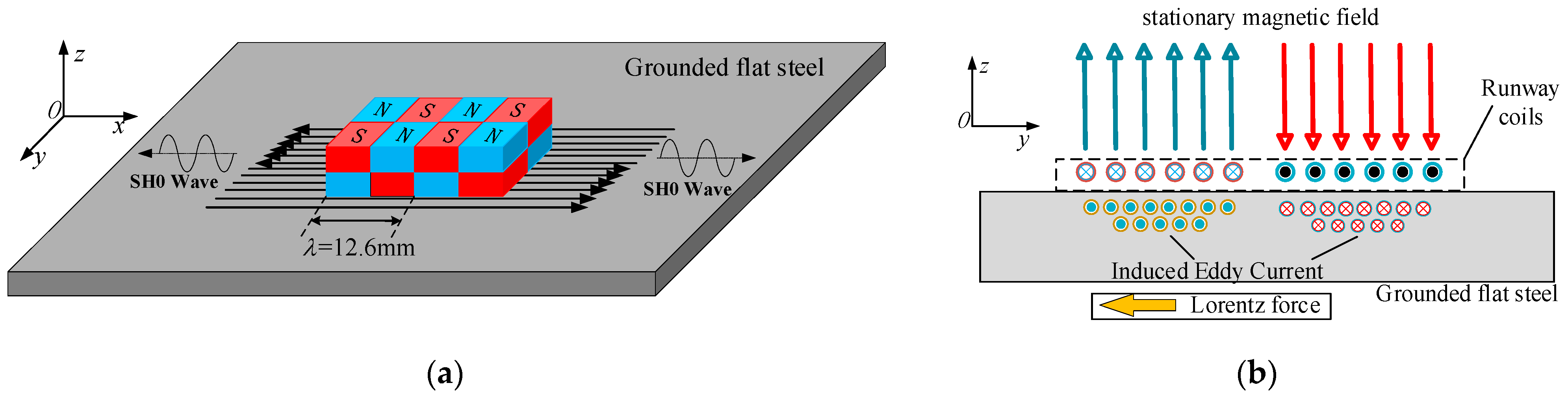
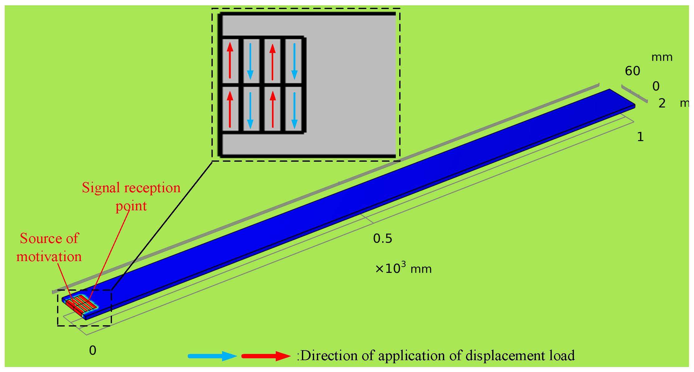
According to the principle of excitation of an electromagnetic ultrasonic SH guided wave transducer, when the coil is energized, a Lorentz force of equal magnitude is generated in the opposite direction under the two adjacent magnets. The Lorentz force causes horizontal shear vibration (y-direction offset vibration) inside the grounded flat steel, which excites the SH0 wave. As illustrated in
Figure 4, a three-dimensional finite element simulation model was established using the actual parameters of the grounded flat steel of the transmission tower as the reference.
In the model, the length of the grounded flat steel is 1000 mm, the width is 60 mm, and the thickness is 5.8 mm. Specifying the material parameters of the flat steel, the Young’s modulus
E is 210 GPa, the Poisson
ν is 0.33, and the density
ρ is 7850 kg·m
−3. On one side of the grounded flat steel model, a 25.2 mm × 40 mm excitation loading area is divided into six pairs of minor loading areas (6.3 × 20 mm). In order to imitate the actual vibration on the flat steel, the horizontal shear displacements are loaded in each loading zone using the specified displacement function under the COMSOL solid mechanics module, as shown in
Figure 4. There is a 180° phase difference between the displacements loaded in adjacent regions in order to simulate the horizontal shear vibration generated by the electromagnetic ultrasonic transducer on the grounded flat steel in an actual situation.
The simulation model’s loading signal is then selected as a Gauss window-modulated sinusoidal signal with a center frequency of 250 kHz and applied with a specified displacement. The expression of the loading signal is
where
c represents the signal amplitude coefficient,
a is the bandwidth coefficient,
b is the loading signal symmetry axis correlation coefficient, and
f is the center frequency of the loading signal; for each parameter, the values are
c = 1 × 10
−7,
a = 2 × 10
10, and
b = 2 × 10
−5, respectively.
The grid density determines the computational error o and impacts the efficiency and cost of numerical simulations. A 250 MHz electromagnetic ultrasound transducer was used in this study. It excites ultrasound guided waves with a wavelength of 6.3 mm and a wave speed of 3170 m/s. COMSOL officially recommends a meshing of approximately 1/6λ for ultrasound simulations. Therefore, we selected grid sizes of 1 mm, 2 mm, and 4 mm to evaluate the sensitivity of the grid on simulation results. When using different grid sizes, an error of only 2.1% for 2 mm grids was compared to the 1 mm grid, which is acceptable for ultrasonic simulations. However, when the grid size increased to 4 mm, the error exceeded 15%, indicating that a more extensive grid division would not be feasible. Thus, considering the convergence of the simulation model and computational cost, free tetrahedral cells were chosen to divide the model into grids, with a maximum cell size set at 1 mm and a calculation time step set at 4 × 10⁻⁸ s to ensure the accuracy of the calculation results.
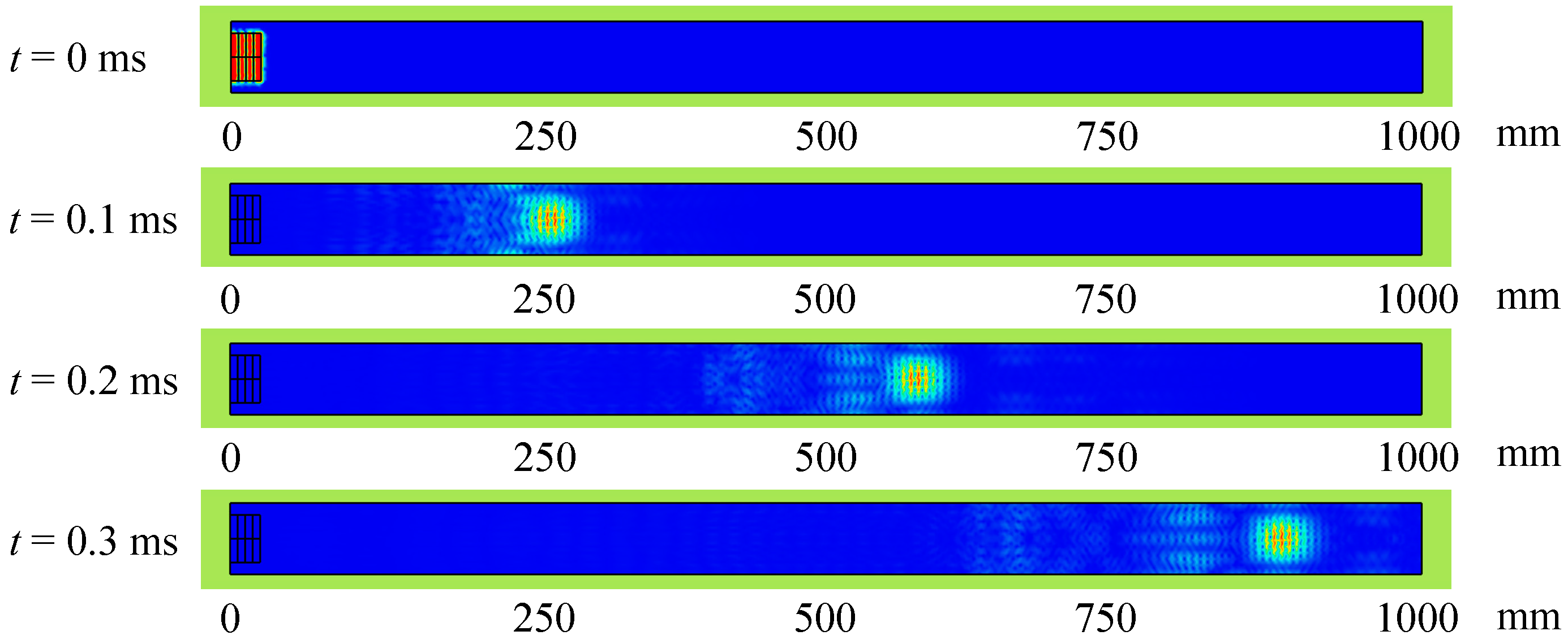
3.2. SH0 Wave Propagation Characteristics and Attenuation Characteristics in Grounded Flat Steel
The grounding flat steel of a power transmission tower is buried underground for a long time, and the surrounding environment is complex; consequently, the propagation process of the SH0 wave in the grounding flat steel is affected by soil pressure, temperature, transmission distance, and other factors, resulting in attenuation of the ultrasonic signal. To investigate the influence of the detection distance on SH0 wave propagation attenuation, we assume that the grounded flat steel is under the same ambient temperature and the soil pressure without considering the soil around the flat steel to absorb the attenuation of the guided wave. The propagation cloud of the SH0 wave in the flat steel at different moments obtained by simulation is shown in
Figure 5.
During the SH0 wave propagation process, there are no other form of ultrasonic waves except for boundary echoes, and mode change does not occur. Due to the superposition of the boundary echo on both sides of the grounded flat steel, the ultrasonic waves propagate faster in the central beam region than in the side flaps.
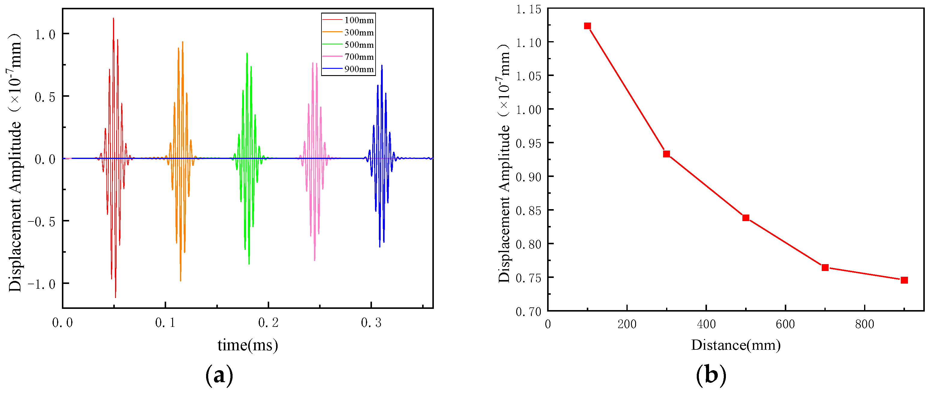
In the model, the signal receiving points are set at 200, 400, 600, 800, and 1000 mm from the excitation source and the amplitude of the guided wave signal at each receiving point is solved. The guided wave signal at each site and the characteristic curve of SH guided wave attenuation in the flat steel are shown in
Figure 6a and 6b, respectively.
The amplitude of the guided wave decreases with the increase in the guided wave propagation distance. The equation for the linear attenuation coefficient α of the guided wave is as follows:
where
A1 is the signal amplitude of the guided wave at the start receiving point,
A2 is the signal amplitude of the guided wave at the end receiving point,
L is the distance between the start and end monitoring points, and the attenuation coefficient of the SH0 wave in the flat steel is 0.0016 dB/mm, indicating that the long-distance detection of grounded flat steel by ultrasonic SH0 guided wave is feasible.
3.3. Inverse Transmission Characteristics of SH0 Wave and DAC Curve
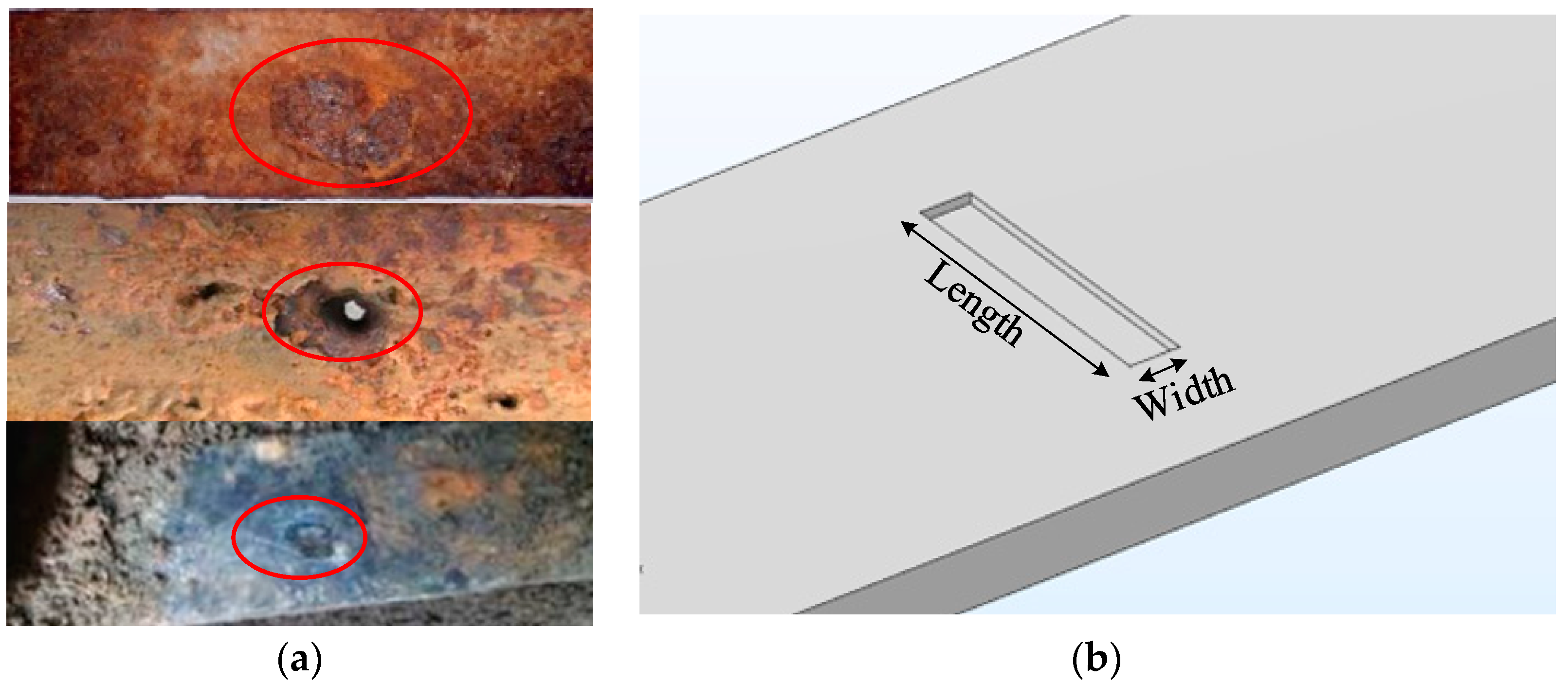
After long-term service, grounded flat steel is prone to local corrosion. Its corrosion morphology varies depending on the local environmental conditions.
Figure 7a shows that the corrosion pit morphology is more common [
1]. According to the detection principle of ultrasonic guided waves, when confronting a defect during propagation, a certain proportion of the reflected waves are returned at the location of the defect. The amplitude of the reflected signal is related to the depth and length of the defect. However, in reality, the morphology of corrosion defects varies, making it impractical to simulate every circumstance in research. Therefore, for the convenience of modeling and calculation, we chose the most representative form of groove defects for the study.
As shown in
Figure 7, we set a groove defect on the centerline of the grounded flat steel using a 30 × 5 × 1 mm groove defect as an example; by varying the specification parameters of the groove defect model, we investigated the reflection and transmission of the guided wave acting on the defect and the effect of the defect location on the amplitude of the guided wave signal.
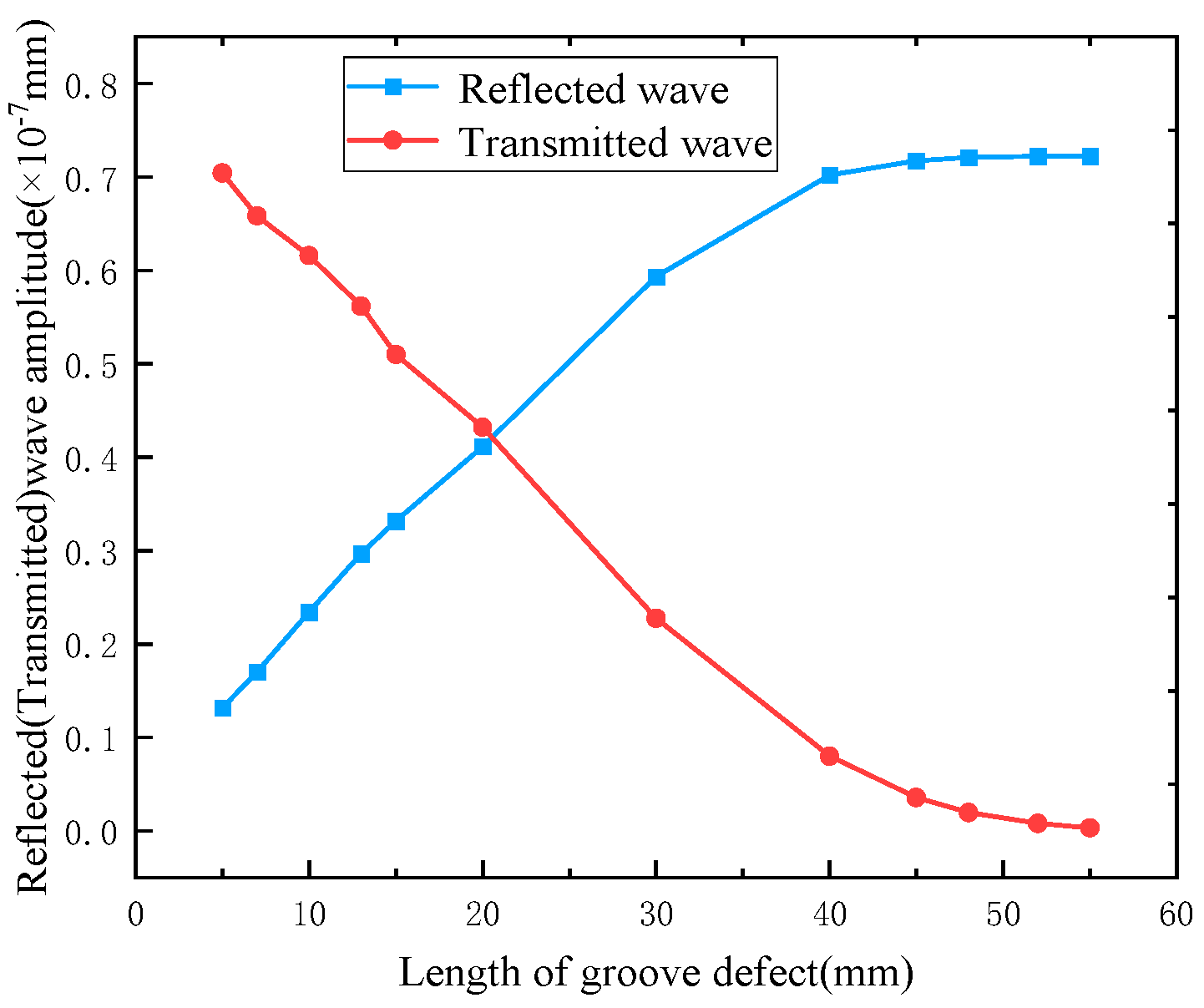
We set up a through-groove defect (20 × 5 × 5.8) at 350 mm from the excitation source and defined the signal receiving point at 100 mm at each end of the groove defect. We then changed the length of the groove defect. The trend of the reflected and transmitted wave amplitudes at the receiving point are shown in
Figure 8 below.
As the length of the defect increases, both the amplitude of the reflected guided wave and the amplitude of the transmitted wave progressively decrease. However, when the defect length is relatively short, the detected echo signal experiences a significant amplitude decline with increasing defect length. In contrast, when the defect length is sufficiently large, the growth rate of the detected echo signal amplitude slows down, eventually approaching a stable state as the defect length continues to increase.
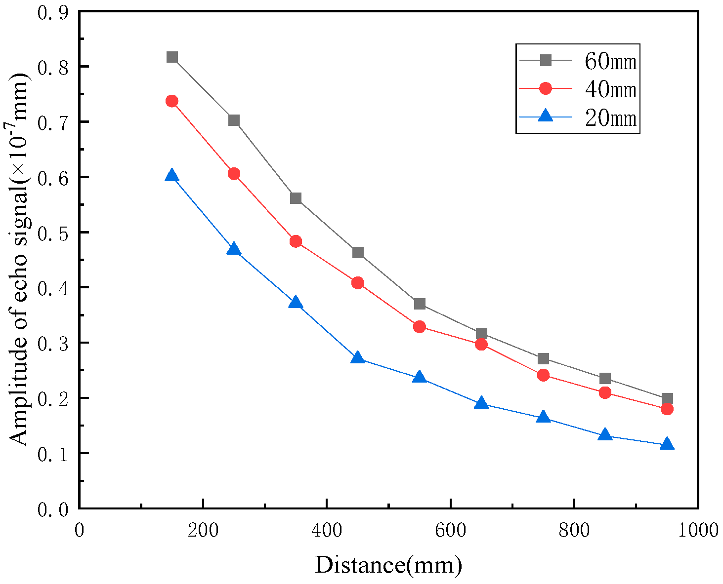
To investigate the impact of different defect variations on defect echoes, we modified the position and width of the defects in the model to simulate the guided wave displacement field in the flat steel for each scenario. The resulting DAC curves for each defect are shown in
Figure 9.
The amplitude of a defective echo is augmented proportionally with the size of the defect. As the length of the corrosion defect increases, the surface area of ultrasonic reflection increases as well, resulting in an increase in the energy of the reflected echo and the echo amplitude. Similarly, for identical corrosion defects, the amplitude of the echo diminishes with an increase in detection distance. Moreover, the rate of decline gradually decelerates.
3.4. The Relationship between the Size of the Grounding Flat Steel Corrosion Defects and the Echo Amplitude
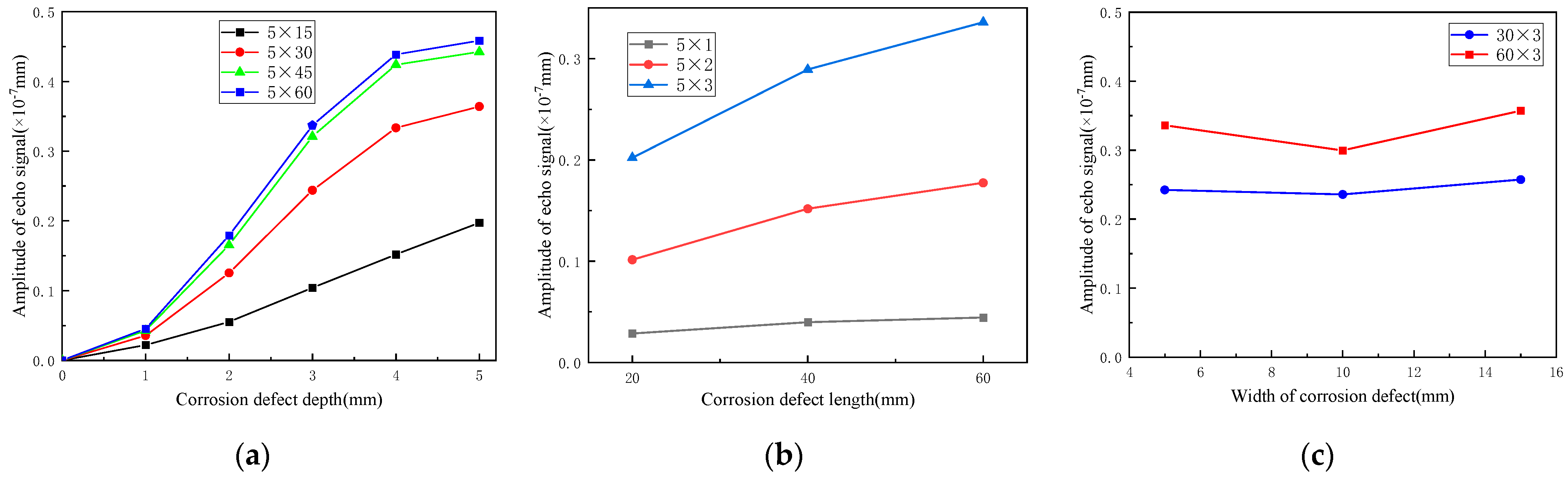
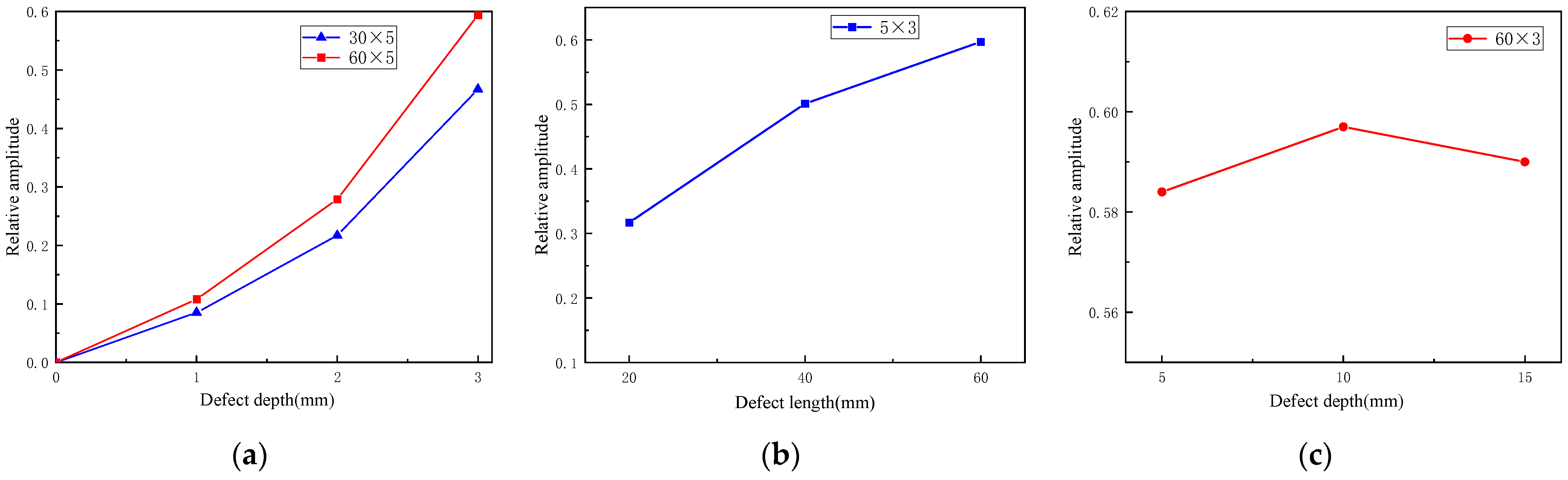
Starting with the width of the corrosion defect at 5 mm, we changed the length and depth of the corrosion defect, examined the effect of different corrosion depths and lengths on the amplitude of the ultrasonic guided wave, and plotted the depth and width of the corrosion defect and the relationship curve of the echo amplitude, as shown in
Figure 10a and
Figure 10b, respectively.
By conducting simulation calculations on corrosion defect widths of 5, 10, and 15 mm for guided wave detection, we found a relationship between the corrosion defect width and the echo signal amplitude, as can be seen in
Figure 10c.
The reflection of the grounding flat steel defect echo becomes more pronounced with the increase in the depth of the defect, as reflected by the change in the displacement amplitude of the defect echo signal. Specifically, the defect reflection echo’s displacement amplitude increases with the defect depth. Furthermore, the echo signal’s displacement amplitude rises with the corrosion defect’s length. However, the defect width has almost no effect on the echo amplitude; as the corrosion defect width increases, the echo amplitude shows no significant variation trend. In summary, the defect echo is positively correlated with the defect depth and length, while the defect width has little effect on the echo amplitude.
4. Experiments
4.1. Experimental Equipment and Samples
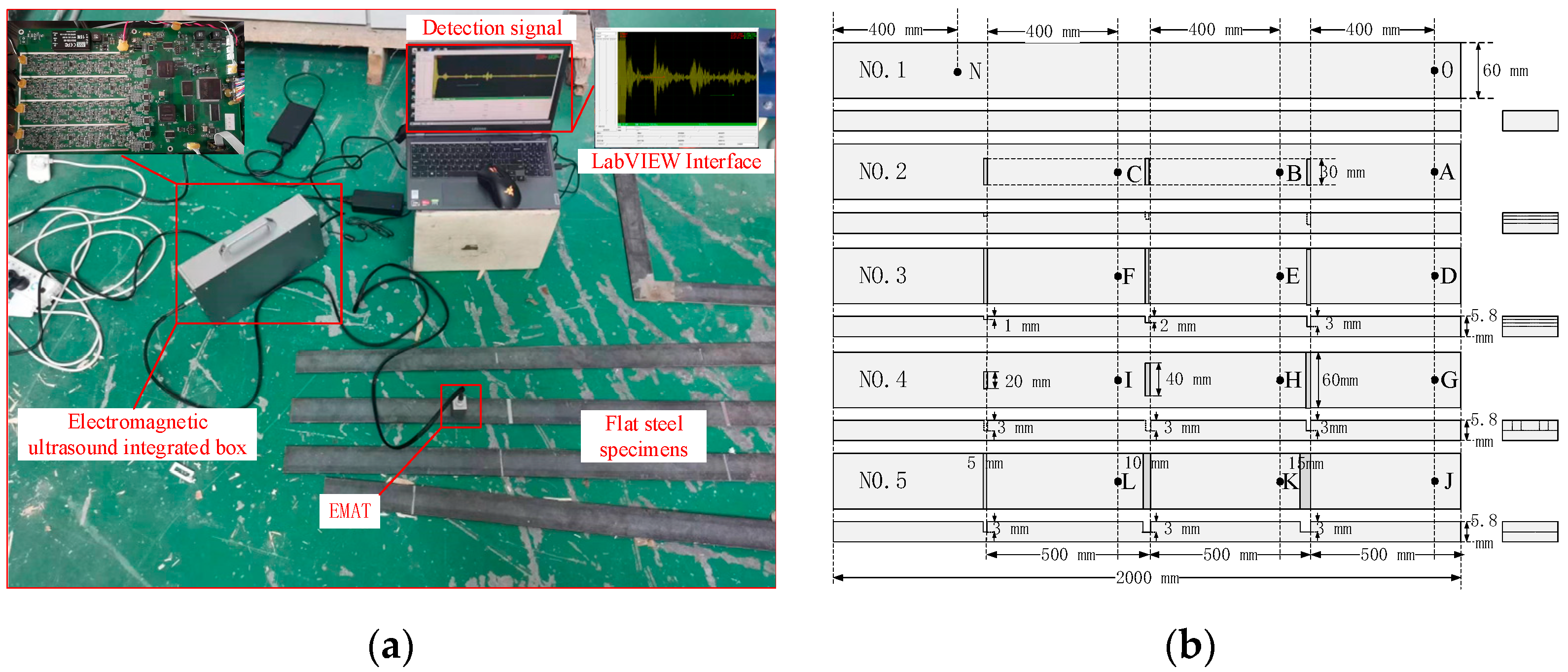
The ultrasonic testing platform used for detecting defects in flat steel is shown in
Figure 11a. It comprises an electromagnetic ultrasonic chamber, an electromagnetic ultrasonic transducer, a flat steel specimen, and a laptop computer (LabVIEW). The electromagnetic ultrasound box is an integrated device that houses a signal generation module, power amplification, impedance matching, pre-amplification, filter, and data acquisition card modules. During testing, the signal generation module furnishes a 250 kHz bipolar six-period square wave pulse as the excitation signal. After power amplification, this signal propels the electromagnetic ultrasonic transducer to emit an ultrasonic guided wave. The resultant echo vibration signal is then gathered by the ultrasonic transducer, filtered, amplified, and ultimately transformed into an electrical signal. Finally, the data acquisition card transmits this electrical signal to the computer.
Typically, transmission towers employ Q235 flat steel as their grounding electrode. Therefore, five Q235 flat steel specimens (NO. 1, 2, 3, 4, 5), each measuring 2000 mm in length, 60 mm in width, and 5.8 mm in thickness, were selected for the test. The specimens and their defective structure schematic diagram are shown in
Figure 11b.
Among them, No. 1 is a defect-free sample; No. 2 is a manually manufactured sample with three groove defects of 5 mm in length, 30 mm in width, and 1, 2, and 3 mm in depth, with a distance of 500 mm between each defect; in No. 3 the defects are widened to 60 mm from those in No. 2; No. 4 has three groove defects of 3 mm in depth, 5 mm in width, and 20, 40, and 60 mm in length; and No. 5 has groove defects of 60 × 3 in length and depth and 5, 10, and 15 mm in width.
4.2. Detection Results at Different Detection Distances and in the Presence of Defects
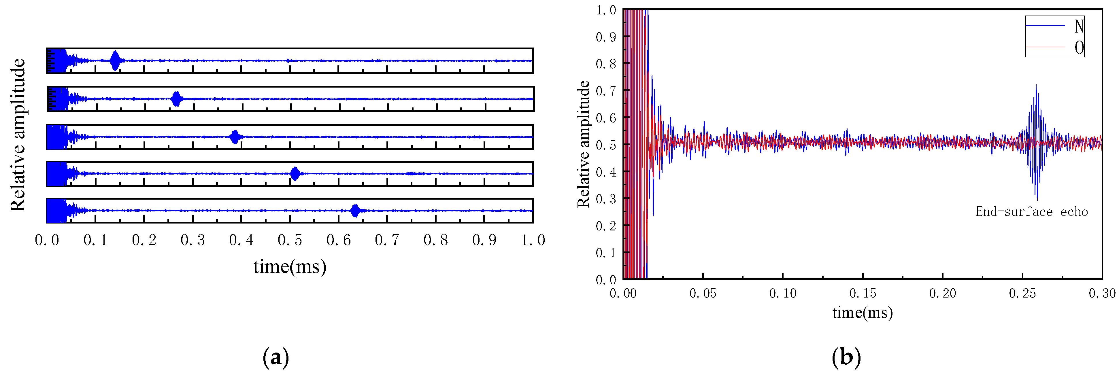
We adjusted the position of the electromagnetic ultrasonic transducer and measured the guided wave echo signal every 200 mm on the right end face of the No. 1 flat steel specimen. The test results are shown in
Figure 12a.
According to the test findings, as the electromagnetic ultrasonic transducer moves farther away from the right end face of the flat steel, the echo signal appears later, while the echo amplitude tends to decrease gradually, which is consistent with the theoretical and simulation results.
For the selected flat steel specimen No. 1, the electromagnetic ultrasonic transducer was placed at the O point and N while using the self-transmitting and self-accepting method for detection. The detection signal is shown in
Figure 12b.
The electromagnetic ultrasonic transducer initiates the SH0 wave, which propagates through the flat steel from the detection point N, interacts with the end face of the flat steel, and generates an echo signal. After propagating back to the electromagnetic ultrasonic transducer, the signal is received and uploaded to the laptop. The propagation distance of the electromagnetic ultrasonic SH0 wave at this time is 800 mm, with a propagation time of 0.259 ms (the difference between the excitation of the electromagnetic ultrasonic transducer signal and the moment corresponding to the peak of the reflected echo signal). The propagation speed of the surface wave in the steel plate is calculated to be 3174.6 m/s, with an error of only 0.14% from the theoretical wave speed of 3170 m/s. The test results demonstrate that the SH0 wave effectively identifies corrosion defects in flat steel, providing high-accuracy defect positioning.
4.3. Impact of Different Depth, Length, and Width of Corrosion Defects on the Test Results
To investigate the impact of corrosion defect depth on the results of electromagnetic ultrasonic SH0 wave detection in flat steel, we selected specimens No. 2 and No. 3. In order to do this, we placed the electromagnetic ultrasonic transducer at points A, B, C, D, E, and F to detect the corrosion defects of 30 mm and 60 mm in length in both specimens. The relationship between the amplitude of the echo signal and the depth of the defect is shown in
Figure 13a.
Similarly, we placed the EMAT at three points G, H, and I of specimen No. 4 and three points J, K, and L of specimen No. 5. We then detected the corrosion defects of varying lengths and widths and obtained the echo amplitude versus the length and width of the corrosion defects, as depicted in
Figure 13b and
Figure 13c, respectively.
The experimental results are consistent with the simulation results, indicating that an increase in the depth and length of a corrosion defect leads to an increase in the defect echo signal. In contrast, the width of the corrosion defect has almost no effect on the amplitude of the echo signal. The impact of defect depth or length on signal growth is relatively small, as shown in both simulation and experimental results, indicating high simulation model accuracy and good consistency with experimental results. Therefore, we conclude that electromagnetic ultrasonic guided waves are suitable for detecting corrosion defects in grounding flat steel transmission towers. Furthermore, the size of corrosion defects can be evaluated using the relationship between the echo amplitude and the defect.
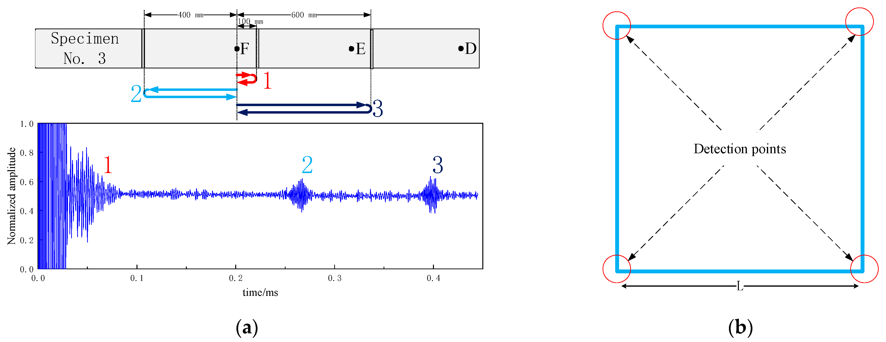
When considering multiple artificial defects in a single sample during an experiment, it follows that the received signal of the transducer will contain multiple echo signals, impeding accurate assessment of the experimental results. Hence, we analyzed the propagation of ultrasonic guided waves in grounded flat steel using an F-point inspection of specimen No. 3 as an illustrative example.
As shown in
Figure 14, when the electromagnetic ultrasonic transducer is at point F for detection, the ultrasonic guided waves encounter three defects in succession during propagation, resulting in three propagation paths labeled 1, 2, and 3. Due to the varying distances between the transducer and each defect and the constant wave velocity of the electromagnetic ultrasonic SH0 wave, the echo signals from each defect appears at different times in the received signal of the transducer. Therefore, by analyzing the diagram’s guided wave propagation paths and transducer signal reception, we can quickly identify the echo signal required for quantitative detection at point F as the number 2 echo. Consequently, in practical testing the position of defects or flat steel surfaces can be determined by analyzing the guided wave velocity and propagation time. However, distinguishing between defects and welded joints requires further analysis with actual construction drawings or excavation inspections. Therefore, to avoid the influence of welded joints, detection is usually carried out by excavating at the four corners of the square-frame-type grounding electrode, as shown in
Figure 14b.
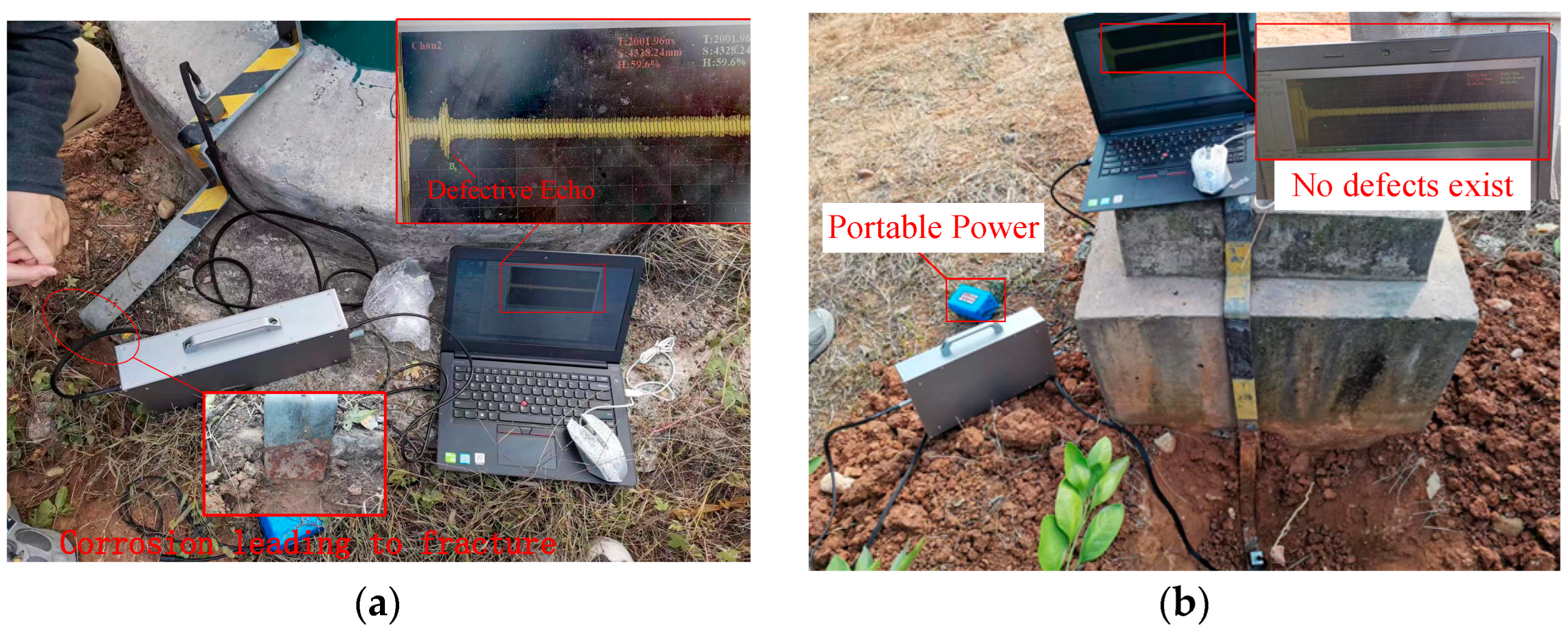
Field detection was carried out on several pole towers with grounding flat steel. According to experimental results, electromagnetic ultrasonic non-destructive testing technology can effectively detect transmission tower grounding flat steel defects and accurately detect corrosion defects in flat steel.
Figure 15a shows an on-site detection result of a case of a steel pipe tower with a grounding lead wire fracture, while
Figure 15b illustrates a case without any corrosion defects.
5. Conclusions
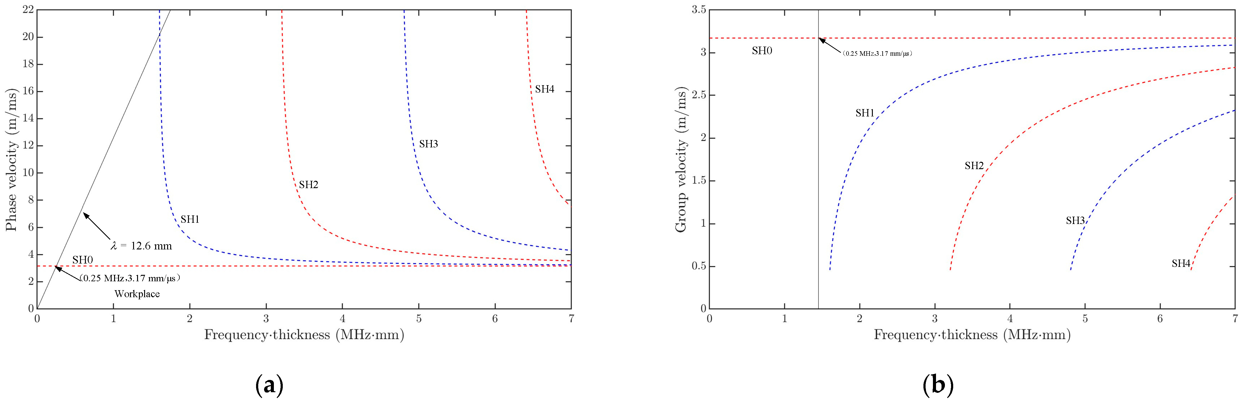
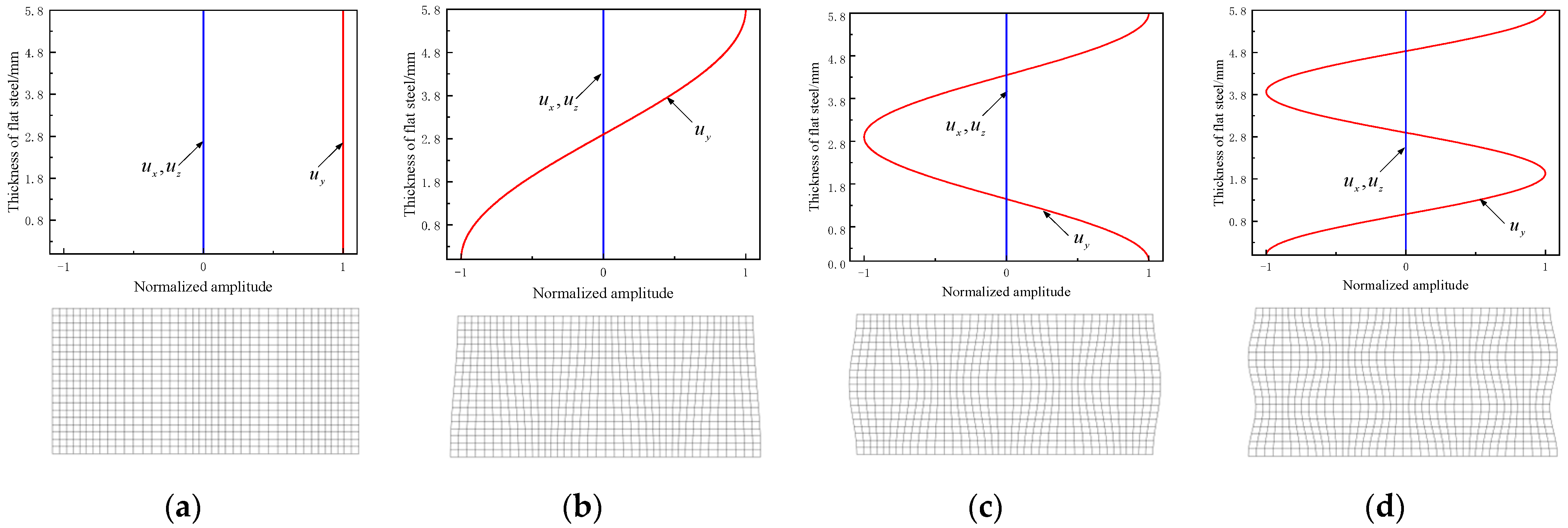
Due to the advantages of fast, accurate, and wide detection range, ultrasonic guided wave technology is used for defect detection of various materials. Based on this, we analyzed the dispersion and guided wave structure of electromagnetic ultrasonic SH waves, studied the attenuation characteristics and inverse and transmission of ultrasonic SH waves in flat steel, and explored the relationship between defect size and the echo signal of flat steel, reaching the following conclusions.
(1) Compared with other higher-order SH waves, the wave structure of SH0 waves is more straightforward and does not disperse when propagating in grounded flat steel. In practical engineering structural defect detection, using SH0 waves can reduce the interference of clutter signals generated by mode conversion, reduce detection complexity, and make the detection signal easier to analyze and identify.
(2) When neglecting the ambient temperature and pressure around the grounded flat steel without considering the attenuation effect of the soil around the flat steel on the absorption of the guided wave, the attenuation coefficient of the SH0 wave in grounded flat steel is only 0.0016 dB/mm, which confirms the feasibility of long-distance detection of grounded flat steel with SH0 waves. The amplitudes of transmitted and reflected waves are different due to the different lengths of flat steel defects; as the defect length increases, the amplitude of the reflected waves gradually increases, while the amplitude of the transmitted waves gradually decreases. The increase in the reflected waves (decrease in the transmitted waves) gradually decreases and stabilizes during the process in keeping with the defect length (from small to large).
(3) For the same corrosion defect, the farther the detected distance is, the smaller the echo signal amplitude is. Flat steel corrosion defect reflected echo amplitude increases with increasing defect depth and length, while the change of defect width has little effect on the SH0 wave reflected echo amplitude.
We used Q235 flat steel for transmission tower grounding devices as the test material. Due to financial constraints, there were few sample materials, the number of experiments was limited, and the experimental data were little. We hope that the data from this study can provide a new method for corrosion detection of power system grounding devices to replace traditional methods such as manual excavation, electromagnetic field analysis, and network nodes. The proposed method can provide a basis for locating and quantitatively detecting defects in transmission tower grounding devices as well as for estimating the operation lifetime of transmission tower grounding devices. In order to further improve the detection accuracy of ultrasonic guided waves, achieve accurate detection and determination of the degree and location of rusting of flat steel, and promote the application of this detection method, further research can be carried out in the following areas.
(1) Further research on the irregularity of defect shape, randomness of defect location, and attenuation characteristics of the soil on ultrasonic waves to measure the degree of roughness due to corrosion, calculate the attenuation component caused by the propagation distance on the ultrasonic guided wave signal, and use it to compensate for the actual detected echo signal amplitude while excluding the influence of detection distance on the detection signal.
(2) Conduct long-term corrosion monitoring on grounded flat steel in transmission towers to establish an assessment system for the working life of grounded flat steel. Through tests, establish the specific relationship between various parameters of corrosion defects and the echo signal amplitude and determine a standard and system for detecting corrosion defects in grounding flat steel.


