Abstract
Urban overpasses, being long-span linear projects, are inevitably affected by ground fissure activities. This study focused on the three-span continuous overpass, and used the MIDAS GTS NX finite element simulation software to establish the model of an urban overpass crossing active ground fissures with different straddling ground fissure positions and hanging wall settlements. This study analyzed the deformation and stress characteristics of soil and bridges induced by ground fissures under different working conditions. The results demonstrate that the soil’s displacement response is mainly concentrated near the ground fissures, and the displacement changes decrease with increasing ground fissures. Ground fissure activities redistribute the stress inside the beam and pier, resulting in the tilting of the pier. When the fissure activity is small, the use of multi-span beams to straddle the ground fissures can effectively reduce the influence of ground fissure activities on bridge deformation. However, when the fissure activity is significant, the bridge may be damaged, and excessive deformation of the bridge and piers may not meet code requirements. In such cases, the multi-span beam structure type should be changed to adapt to the ground fissure activity. The research results provide significant reference value for urban traffic planning and overpass design.
1. Introduction
Ground fissure is a common surface fracture phenomenon. At present, ground fissure disasters occur in many countries and regions in the world, including the United States, Mexico, Ethiopia, New Zealand, China, India, Italy, and other countries [1,2,3,4,5,6,7].
Xi’an is one of the cities in the world most seriously affected by ground fissure disasters [8,9]. Xi’an has 14 ground fissures with a total length of over 100 km and nearly parallel ground fissures distributed in the main urban area that would certainly have serious adverse effects on urban traffic construction [10,11,12]. The ground fissures in Xi’an are generally normal faults [13,14]. The vertical differential movement of the ground fissures forms an influence zone in the stratigraphic section [5,15]. As a hub project of urban traffic and an important transportation facility, overpasses play a vital role in traffic flow management, which can be threatened by ground fissures [16,17,18]. The cumulative dislocation amount of active ground fissures increases year by year, and the threat to bridges increases gradually. Therefore, it is significant to investigate the effect of ground fissure activity on the deformation and failure of bridges [19].
Although a lot of research has been conducted on ground fissures all over the world, the main focus has been on the development characteristics of ground fissures, the shear model of soil, causal mechanisms, and the influence of ground fissure activities on under-ground engineering structures [20,21,22,23,24,25,26,27]. Yan et al. [28] focused on the failure mechanism and deformation characteristics of a utility tunnel based on the Kunming Road utility tunnel crossing f3 ground fissure by finite-difference numerical simulation. Liu et al. [22] studied the seismic response of a segmented metro tunnel with flexible joints passing through active ground fissures in Xi’an by a shaking table model test. A coupling dynamic ground motion was generated in the test model. Following the collapse of a tunnel in Xi’an Metro Line 3 near a ground fissure, the potential causes and corresponding mechanisms were analyzed by Ma et al. [29]. Peng et al. [30] studied the characteristics of surface deformation and structure deformation and the failure mechanism of an underground metro tunnel under ground fissure activities by particle flow numerical analysis and a physical model test, which presented a comprehensive failure mode of bending–shear–torsion when the tunnel crossed the ground fissure with a dip angle of 20° or less. In the study by Miao et al. [31], a simplified solution was proposed to calculate the stratum load and the vertical stress of a metro tunnel under the action of an active ground fissure.
For a long period of time, the research has mainly focused on the seismic vulnerability and the impact of sudden disasters on bridge safety. Bashir et al. [32] developed an assessment strategy for fire-damaged infrastructures based on the implementation of quick diagnostic techniques and consistent interpretation procedures for the overpass, so as to determine the residual safety margin and any need for repair works. In the study by Bashir et al. [33], the seismic vulnerability of the flyover structure incorporating the local site effect is assessed herein. The results obtained are explained in terms of the surface acceleration time history, the ratio of shear stress to effective vertical stress with depth, the acceleration response spectrum, the ratio of amplitude to frequency, etc.
Research on the deformation and failure mechanism of bridges under the action of ground fissures is quite recent. The deck deformation of a simply supported beam bridge and a fixed bridge under ground fissure activity was studied by a large-scale model test [34]. Gao et al. [35] discussed the failure mode and degree of ground fissure activities of urban bridges in Xi’an through examples, and put forward a general prevention and control concept for bridge structures in response to ground fissure activities. Taking the cross-ground fissures in the elevated section of Xi’an Metro Line 3 as an example, it was proposed that when uneven settlement occurred in the foundation, the influence of ground fissures on the elevated line could be reduced by using a simply supported beam bridge and a line slope adjustment scheme [36]. Zhang et al. [37] studied the influence of ground fissure activity on pier stress and track deformation when a high-speed railway bridge traversed the ground fracture zone through a 1:20 model test. Pang et al. [38] carried out a 1:5 model test of a bridge structure across a ground fissure, analyzed the strain situation of the bridge deck and pier during ground fissure activity, and discussed the failure mode of the bridge. Through physical model tests, Wang [39] investigated the overall deformation, concrete pile stresses, and box girder strains of high-speed railway bridges under different ground fissure dislocation amounts and compared them with numerical simulations. Liu et al. [40] established a numerical model of a high-speed rail bridge crossing ground fissures using Fast Lagrangian Analysis of Continua in 3 Dimensions (FLAC3D) and analyzed the deformation of the box girder and the force characteristics of the pile foundation. Yang [41] simulated the hidden ground fissures across the simply supported girder bridges of high-speed railways and analyzed the box girder deformation, pile foundation settlement, and internal force changes when the ground fissures were active. Zhao [42] established a numerical model for steel–concrete composite girder bridges spanning ground fissures and investigated the internal force and deformation characteristics of steel–concrete composite girder bridges when ground fissures were active. Gao [43] established a numerical model of a Cloud Rail simply supported girder bridge spanning active ground fissures and studied the displacement law of the rail girders with piers and pile foundations. Xu et al. [44] investigated the impact of ground fissure activity on underground utility tunnels.
At present, although some achievements have been made in the measurement of ground fissures in bridge projects, the current studies mainly focus on the analysis of the deformation and internal forces of simply supported girder bridges during ground fissure activities using examples, model tests, or numerical simulations, while a few studies have been conducted for multi-span overpasses. Multi-span overpasses, which sacrifice the inclined deformation of the structure to ensure that the deck does not suffer crack damage, are a widely used form of overpass at present. However, there has been little study on multi-span overpasses crossing active ground fissures. The purpose of this study was to investigate the effect of ground fissure activity on urban multi-span overpasses by using a numerical simulation method and to provide references for the disaster mechanism and rational design of overpasses that have been built, or are under construction, and overpasses that will be built in future.
In order to reduce the influence range of ground fissure activity on the overpass, a simple supported beam structure is adopted for bridges across ground fissure zones. Although this structure type has no significant effect on the internal force of the box girder, the excessive settlement displacement will reduce the contact area between the box girder and spacer and cause the lateral restraint of the girder to be reduced, which is a safety hazard. The interchange bridge has strict requirements on the longitudinal inclination angle of the box girder that is not easy to meet, and a larger span is needed to reduce the inclination angle, increasing the requirements for the construction of the interchange bridge. In the case of weak ground fissure activity, multi-span girders are used to cross the ground fissure, and the influence range of ground fissure activity is increased, but the inclination of each span of the box girder can be reduced. In order to analyze the force and deformation response mechanism of the multi-span beam across the ground fissures, a finite element model of the active ground fissure passing through the multi-span overpass from different locations was established.
2. Finite Element Analysis Model
Considering the possible non-hydrostatic steady state of the two-span girders under the action of ground fissure activity, this study takes the three-span continuous interchange bridge orthogonal span riding ground fissure as an example and establishes three kinds of working condition models according to the different locations of the span riding ground fissure. The first working condition is the ground fissure located between piers 1 and 2, the second working condition is the ground fissure located between piers 2 and 3, and the third working condition is the ground fissure located between piers 3 and 4, as shown in Figure 1. The model is 120 m long and 60 m wide, the soil layer is divided into six layers with a thickness of 40 m in total, the ground fissure is orthogonal to the overpass at the middle of each span, and the inclination angle with the ground is 80°. The box girder of the overpass is 32 m long, 12 m wide, and 3.13 m high, and the bridge pier is 9 m high and 6 m wide. The upper box girder is supported by the pad plate, which is 1 m long, 1 m wide, and 0.3 m high. Each cap is set with four concrete piles, each one 30 m long and l m in diameter. The beam element is used to simulate a concrete pile, and the negative friction between the pile and the soil is simulated by the pile–soil contact element. The model length direction is the X-axis, the Y-axis is the model width direction, and the Z-axis is the opposite direction of gravity.
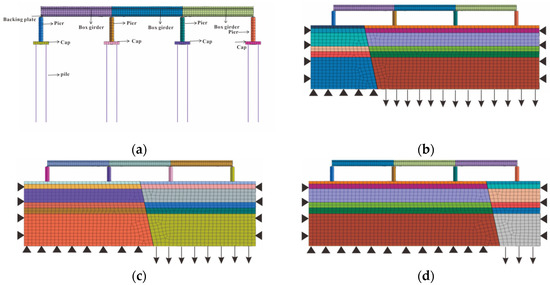
Figure 1.
Analysis model of the three-span continuous beam bridge orthogonally crossing ground fissure activity: (a) Finite element model of overpass; (b) working condition I; (c) working condition II; (d) working condition III (the colors in Figure 1 have no practical meaning, which are generated with the establishment of the model. From top to bottom, the soil layers are mixed fill soil, loess, loess, paleosoil, and loess separately).
2.1. Material Constitutive Model and Parameters
The Mohr–Coulomb model is used for the soil material, and the elastic model is used for the concrete beam and steel mat material. Taking the actual stratum of Xi’an as an example, the physical and mechanical parameters related to the soil and bridge structure materials are shown in Table 1 and Table 2.

Table 1.
Physical and mechanical parameters of soil materials [39,40,41].
Table 2.
Physical and mechanical parameters of bridge structure materials [44,45].
2.2. Boundary Conditions and Contact Technology Processing
Normal constraints are set in the same direction on the left and right sides in the X and Y directions and on the two end-face boundaries in the longitudinal direction. In the vertical direction, the stratigraphic surface is free, the vertical constraint is set at the bottom of the lower plate of the ground fissure, and the forced vertical displacement is set at the bottom of the hanging wall of the ground fissure to simulate the ground fissure settlement. Contact elements are used in the contact between the box girder and backing plate, between the backing plate and pier, between the pier and cap, and between the pile and soil.
Ground fissures have a certain opening and are often filled with various cemented particles. In this regard, the interface unit is used for surface contact simulation to simulate the movement of ground fissures. The surface contact mainly controls the ground fissure contact slip through the normal stiffness (Kn), the shear stiffness (Ks) of the pile–soil contact unit, the cohesive force c, and the internal friction angle φ of the soil layer.
2.3. Calculated Working Conditions
The recent rate of ground fissure activity in Xi’an is 1–5 mm/a, and the designed service life of the bridge is 100 years; so, the maximum settlement difference of ground fissures during the service life is considered to be 500 mm. To more accurately analyze the response of the bridge structure displacement and internal force under the change in settlement amount in the hanging wall of the fissures, five kinds of settlement amounts of ground fissures are incremented by 10 cm each time, and the maximum settlement amount is taken as 50 cm.
3. Calculation Results and Analysis
3.1. Analysis of Calculation Results in Case 1
The horizontal and vertical displacement maps of settlement amounts of the hanging wall of the ground fissure of 10 cm, 20 cm, 30 cm, 40 cm, and 50 cm are shown in Figure 2. It can be seen that when the settlement amount of the hanging wall increases, the displacement and deformation of the soil and the overpass increase, and their displacement and deformation are related to the relative position of the ground fissure. The closer the horizontal displacement is to the ground fissure, the greater the impact, and the farther the horizontal displacement is from the ground fissure, the smaller the impact. The maximum vertical displacement is near the middle span.
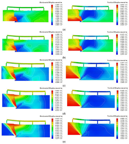
Figure 2.
Overall displacement map under different settlements of the hanging wall of the ground fissure: (a) S = 10 cm; (b) S = 20 cm; (c) S = 30 cm; (d) S = 40 cm; (e) S = 50 cm.
In the analysis of the influence of the change in settlement amount in the hanging wall of the ground fissure on the bridge pier displacement and deformation, the vertical direction displacement difference between the top and bottom of the pier is very small due to the stiffness of the bridge pier and could be ignored; therefore, only the displacement of the top and bottom of the pier in the horizontal direction is considered. The horizontal displacement of the top and bottom of each pier is shown in Table 3. With the displacement difference between the top and bottom divided by the height of the pier, the inclination of each pier under different settlement amounts can be obtained as shown in Figure 3.
Table 3.
Horizontal displacement of bridge pier.
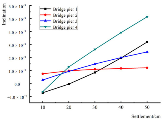
Figure 3.
The inclination of each bridge pier under different settlement amounts.
The piers are numbered sequentially from the lower plate to the hanging wall. The tilt of Pier No. 4 in the hanging wall of the ground fissure is the largest during settlement, and the tilt is 0.51% when the settlement is 50 cm; Pier No. 1 in the lower plate of the ground fissure is the second largest, and the tilt is 0.32% when the settlement is 50 cm; Pier No. 3 in the hanging wall has a tilt of 0.24% when the settlement is 50 cm; for Pier No. 2 in the hanging wall, the pier tilt is the smallest; when the settlement is 50 cm, the tilt is 0.12%. The Specification for the Design of Foundations and Foundations for Highway Bridges and Culverts (JTG D63-2019) stipulates that the pier inclination should not exceed 0.2%. It is observed that when the vertical settlement of the ground fissures exceeds 20 cm, the tilt of the bridge pier may exceed the specification requirement.
By extracting the displacement data of the box girders, the difference in horizontal direction displacement between the left and right parts of the box girders at different settlement amounts produced by the hanging wall of the ground fissure is very small and could be ignored; hence, only the displacement of the box girders in the vertical direction is analyzed. The vertical displacement of the nodes at the left and right end positions of the extracted box girder is shown in Table 4, and the settlement difference between the left and right sides of the beam at different positions is divided by the span to obtain the inclination of each box girder at different settlement amounts as shown in Figure 4. The inclination of the left-span box girder across the ground fissure is the largest, and the inclination is 1.14% when the settlement is 50 cm; the inclination of the middle-span box girder is the second largest, and the inclination is 0.21% when the settlement is 50 cm; the inclination of the right-span box girder is the smallest, and the inclination is 0.052% when the settlement is 50 cm.
Table 4.
Vertical displacement of each span of the box girder.
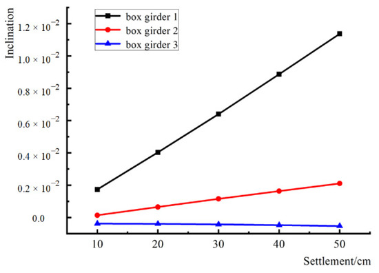
Figure 4.
The inclination of box girder under different settlement amounts.
As shown in Figure 4, the inclination angle of the box girder across the ground fissure is the largest, and the inclination angle of the box girder away from the ground fissure is almost unchanged. The Specification for the Design of Foundations and Foundations of Highway Bridges and Culverts (JTG D63-2019) stipulates that the uneven settlement difference between adjacent piers should not cause the bridge deck to form an additional longitudinal slope of more than 0.2%. When the vertical settlement of the ground fissure exceeds 10 cm, the left-span inclination across the ground fissure exceeds the specification limit.
During the settlement of the hanging wall of the ground fissure, a large longitudinal stress is generated in the box girder, and when the settlement is 10 cm, the stress map is shown in Figure 5. It is observed that the maximum tensile stress in the box girder is 20.5 MPa, while the ultimate tensile stress of C50 concrete is 5 MPa, which means that tensile damage occurs in the box girder concrete when the active settlement of the ground fissure seam is greater than 10 cm.
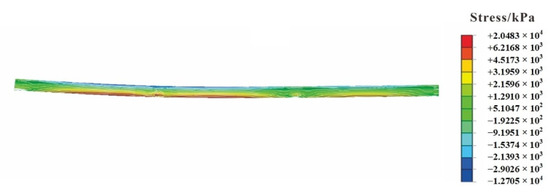
Figure 5.
Longitudinal stress of box girder under 10 cm settlement.
3.2. Analysis of Calculation Results in Case 2
The horizontal and vertical displacement maps of the model as a whole when the settlement of the hanging wall is 10 cm, 20 cm, 30 cm, 40 cm, and 50 cm in the middle span of the overpass span riding ground fissure condition are shown in Figure 6.
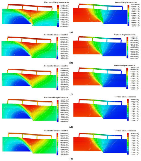
Figure 6.
Overall displacement map under different settlements of the hanging wall of the ground fissure: (a) S = 10 cm; (b) S = 20 cm; (c) S = 30 cm; (d) S = 40 cm; (e) S = 50 cm.
The horizontal displacement at the top and bottom of the pier is determined, as shown in Table 5. The slope of each pier at different settlement amounts is shown in Figure 7. When the settlement amount is 50 cm, the slope of the No. 1 bridge pier at the footwall of the ground fissure is the largest in the settlement process, with a slope of 0.64%. Pier No. 2 of the footwall of the ground fissure takes second place, with a dip of 0.54%. Pier No. 4 at the hanging wall inclines by 0.50%. Additionally, the tilt of 0.12% of Pier No. 3 located on the hanging plate is the smallest. It is observed that when the vertical settlement of ground fissures exceeds 10 cm, the slope of the bridge pier may exceed the specification requirements.
Table 5.
Horizontal displacement of bridge pier.
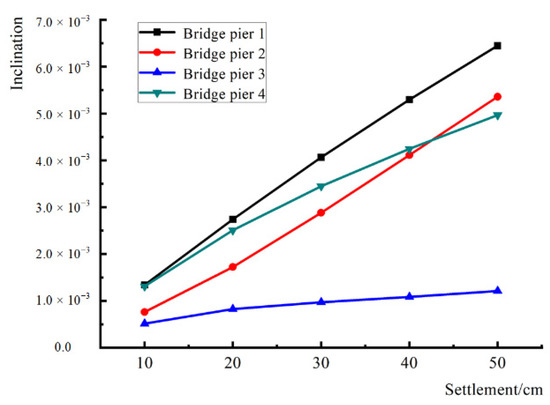
Figure 7.
The inclination of each bridge pier under different settlement amounts.
The vertical displacement of the nodes at the left and right ends of each span of the box girder is shown in Table 6, and the inclination of each box girder under different settlement amounts is shown in Figure 8. When the settlement is 50 cm, the mid-span box girder across the ground fissure has the largest inclination, which is 0.96%, followed by the left side of the footwall of the ground fissure, with a slope of 0.44%. The right side of the upper wall of the floor fissure has the smallest inclination, which is 0.32%. When the vertical settlement of the ground fissure exceeds 10 cm, the mid-span inclination across the ground fissure exceeds the standard limit.
Table 6.
Vertical displacement of each span of the box girder.
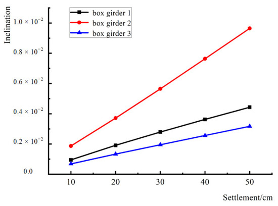
Figure 8.
The inclination of box girder under different settlement amounts.
During the settlement of the hanging wall of the ground fissure, a large longitudinal stress is generated in the box girder. The stress map for when the settlement is 10 cm is shown in Figure 9.
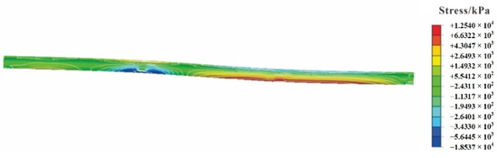
Figure 9.
Longitudinal stress of box girder under 10 cm settlement.
It is observed that the maximum tensile stress in the box girder is 12.5 MPa, while the ultimate tensile stress of C50 concrete is 5 MPa, which means that tensile damage to the box girder concrete occurs when the settlement of the ground fissure joint activity is greater than 10 cm.
3.3. Analysis of Calculation Results in Case 3
The horizontal and vertical displacement maps of the model as a whole, for when the hanging wall settlement is 10 cm, 20 cm, 30 cm, 40 cm, and 50 cm, are shown in Figure 10. It is observed that when the hanging wall settlement increases, the displacement and deformation of the soil and the overpass increase, and the displacement and deformation of the two are related to the relative position of the ground fissure; the closer to the ground fissure, the greater the influence, and vice versa.
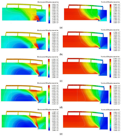
Figure 10.
Overall displacement map under different settlements of the hanging wall of the ground fissure: (a) S = 10 cm; (b) S = 20 cm; (c) S = 30 cm; (d) S = 40 cm; (e) S = 50 cm.
The horizontal displacement of the node at the top and bottom positions of the bridge pier is determined (Table 7). The displacement difference of each pier at different settlement amounts is shown in Figure 11. When the settlement amount is 50 cm, the tilt of Pier No. 1 in the lower plate of the ground fissure is the largest in the settlement process, which is 0.45%, followed by Pier No. 2 in the lower plate of the ground fissure, with a tilt of 0.32%. The tilt of Pier No. 3 in the lower plate of the ground fissure is 0.36%, and the tilt of Pier No. 4 located in the hanging wall is the smallest, which is 0.12%. It is observed that when the vertical settlement of the ground fissure exceeds 10 cm, the tilt of the bridge pier may exceed the specification requirement.
Table 7.
Horizontal displacement of bridge pier.
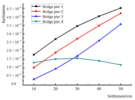
Figure 11.
The inclination of each bridge pier under different settlement amounts.
The vertical displacements of the nodes at the left and right end positions of each span of the extracted box girder are shown in Table 8, and the vertical displacement differences of each box girder at different settlement amounts are shown in Figure 12. When the settlement amount is 50 cm, the tilt of the right-span box girder across the ground fissure is the largest (1.20%); the tilt of the middle-span box girder under the ground fissure is the second largest (0.38%); and the tilt of the left-span box girder under the ground fissure is the smallest (0.017%). When the vertical settlement of the ground fissure exceeds 10 cm, the tilt of the right span across the ground fissure exceeds the specification limit.
Table 8.
Vertical displacement of each span of the box girder.
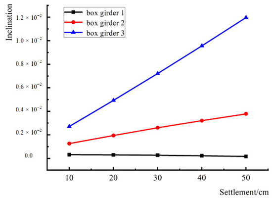
Figure 12.
The inclination of box girder under different settlement amounts.
During the settlement of the hanging wall of the ground fissure, a large longitudinal stress is generated in the box beam. The stress map for when the settlement is 10 cm is shown in Figure 13.
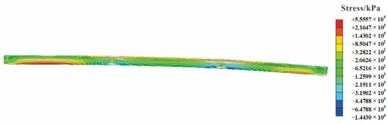
Figure 13.
Longitudinal stress of box girder under 10 cm settlement.
It can be seen that the maximum tensile stress in the box girder is 5.6 MPa, while the ultimate tensile stress of C50 concrete is 5 MPa. When the settlement of the ground fissure joint activity is greater than 10 cm, tensile damage occurs in the box girder concrete.
4. Discussion
To summarize the above data, the limit states under different working conditions are obtained by using linear difference. When the tilt of the pier is 0.2%, the hanging wall of the ground fissure needs to settle 25.5 cm in case 1, 14.7 cm in case 2, and 12.4 cm in case 3; when the tilt of the box girder is 0.2%, the hanging wall of the ground fissure needs to settle 11.2 cm in case 1, 10.7 cm in case 2, and 6.8 cm in case 3.
It is found that, regardless of piers or box girders, when a tilt of 0.2% is produced, the settlement required to produce the hanging wall of the ground fissure is the largest in case 1, the second largest in case 2, and the smallest in case 3, which means that the ability to resist deformation is the strongest in case 1, followed by case 2 and case 3.
When the settlement of the hanging wall of the ground fissure is 10 cm, the maximum stress in the box girder is 20.5 MPa in case 1, 12.5 MPa in case 2, and 5.6 MPa in case 3. Thus, when the same amount of settlement is generated in the hanging wall of the ground fissure, the longitudinal stress in the box girder of case 3 is the smallest, followed by case 2, and the maximum longitudinal stress in the box girder is in case 1.
In addition, if the same span of the simply supported beam is used across the ground fissure, when the span is 40 m, and the box girder produces a 0.2% tilt, the hanging wall of the ground fissure needs to settle 8 cm, during which the interchange produces an additional internal force. It is found, however, that the ground fissure in the form of a simply supported beam span rider does not produce additional internal forces in the box girder, and its maximum allowable settlement is not increased significantly. Although the internal force of the multi-span beam is greater than the allowable stress, when the demand for allowable settlement cannot be satisfied by using the simply supported beam, the feasibility of replacing the structural form, such as a multi-span steel box girder instead of a concrete structure, can be improved by increasing the strength of the beam to improve the feasibility of the interchange across the ground fissure without stress damage to the box girder.
5. Conclusions
Using the Midas GTS NX software, three mechanical models of three-span continuous girder overpasses that straddle the ground fissures at different positions orthogonally were established, the deformation and stress characteristics of the box girder and the bridge pier under different settlements of the ground fissure upper wall were analyzed, and the results were obtained. Conclusions can be drawn as follows:
(1) When the settlement is generated in the hanging wall of the ground fissure, both the horizontal and vertical displacements of the soil increase with the accumulation of settlement in the hanging wall, and the closer it is to the ground fissure, the more significant the uneven distribution is.
(2) Under the effect of settlement in the hanging wall of the ground fissure, the bridge piers and box girders produce differential settlement and tilt. The further away from the ground fissure, the greater the tilt of the bridge pier. The tilt of the pier located in the lower plate is greater than that of the hanging wall. The vertical displacement tilt of the box girder across the riding ground fissure is the largest.
(3) When a tilt of 0.2% is generated, the ability to resist deformation is the strongest in case 1, followed by case 2 and case 3, regardless of whether it is a pier or a box girder.
Although the simply supported beam type does not generate additional internal force in the structure, the allowable amount of ground fissure activity is small, and the box girder type with higher tensile strength can be used to adapt to the larger ground fissure activity.
Author Contributions
Conceptualization, Y.C., P.W. and Q.X.; methodology, Y.C.; software, Y.C.; validation, Y.C., P.W. and Q.X.; formal analysis, Y.C.; investigation, Y.C.; resources, Y.C.; data curation, Y.C., P.W. and Q.X.; writing—original draft preparation, Y.C.; writing—review and editing, Y.C.; visualization, Y.C.; supervision, Y.C.; project administration, Y.C. All authors have read and agreed to the published version of the manuscript.
Funding
This research received no external funding.
Institutional Review Board Statement
Not applicable.
Informed Consent Statement
Not applicable.
Data Availability Statement
Not applicable.
Acknowledgments
The authors would like to thank the Key Laboratory of Mine Geological Hazards Mechanism and Control, Ministry of Natural Resources. In addition, we thank the reviewers and the editors for their valuable comments, which improved the quality of this paper.
Conflicts of Interest
The authors declare no conflict of interest.
References
- Leonard, R.J. An Earth Fissure in Southern Arizona. J. Geol. 1929, 37, 765–774. [Google Scholar] [CrossRef]
- Rudolph, D.L.; Cherry, J.A.; Farvolden, R.N. Groundwater Flow and Solute Transport in Fractured Lacustrine Clay Near Mexico City. Water Resour. Res. 1991, 27, 2187–2201. [Google Scholar] [CrossRef]
- Ayalew, L.; Yamagishi, H.; Reik, G. Ground Cracks in Ethiopian Rift Valley: Facts and Uncertainties. Eng. Geol. 2004, 75, 309–324. [Google Scholar] [CrossRef]
- El Baruni, S.S. Earth Fissures Caused By Groundwater Withdrawal In Sarir South Agricultural Project Area, Libya. HYJO 1994, 2, 45–52. [Google Scholar] [CrossRef]
- Lee, C.F.; Zhang, J.M.; Zhang, Y.X. Evolution and Origin of the Ground Fissures in Xian, China. Eng. Geol. 1996, 43, 45–55. [Google Scholar] [CrossRef]
- Allis, R.G. Review of Subsidence at Wairakei Field, New Zealand. Geothermics 2000, 29, 455–478. [Google Scholar] [CrossRef]
- Gaur, V.P.; Kar, S.K.; Srivastava, M. Development of Ground Fissures: A Case Study from Southern Parts of Uttar Pradesh, India. J. Geol. Soc. India 2015, 86, 671–678. [Google Scholar] [CrossRef]
- Howard, K.W.F.; Zhou, W. Overview of Ground Fissure Research in China. Environ. Earth Sci. 2019, 78, 97. [Google Scholar] [CrossRef]
- Xu, J.; Peng, J.; Deng, Y.; Wang, F. Development Characteristics and Formation Analysis of Baixiang Earth Fissure on North China Plain. Bull. Eng. Geol. Environ. 2019, 78, 3085–3094. [Google Scholar] [CrossRef]
- Chen, X.U.; Liqun, Y.; Yuming, M.E.N.; Lei, L.I.U.; Mi, Y. Dynamic model test for response of tunnel-stratum crossing ground fissure under vibration of metro. J. Eng. Geol. 2018, 26, 1360–1365. [Google Scholar] [CrossRef]
- He, G.; Huang, Q.; Wang, T.; Liu, N. Numerical analysis of dynamic response of high-speed railway subgrade orthogonally crossing ground fissure zone. J. Eng. Geol. 2020, 28, 149–157. [Google Scholar] [CrossRef]
- Zhao, Y.; Huang, Q.; Xiao, S.; Gou, Y.; Wang, Y. Study on optimization of crd construction method of metro tunnel through the ground fissure site. J. Eng. Geol. 2021, 29, 516–525. [Google Scholar] [CrossRef]
- Liu, N.; Huang, Q.; Wang, L.; Fan, W.; Jiang, Z.; Peng, J. Dynamic Characteristics Research of a Ground Fissure Site at Xi’an, China. Tunn. Undergr. Space Technol. 2018, 82, 182–190. [Google Scholar] [CrossRef]
- Zhu, C.; Chen, Z.; Huang, Y. Coupled Moving Particle Simulation–Finite-Element Method Analysis of Fluid–Structure Interaction in Geodisasters. Int. J. Geomech. 2021, 21, 04021081. [Google Scholar] [CrossRef]
- Zhu, C.; Huang, Y.; Sun, J. Solid-like and Liquid-like Granular Flows on Inclined Surfaces under Vibration—Implications for Earthquake-Induced Landslides. Comput. Geotech. 2020, 123, 103598. [Google Scholar] [CrossRef]
- Peng, J.; Qiao, J.; Sun, X.; Lu, Q.; Zheng, J.; Meng, Z.; Xu, J.; Wang, F.; Zhao, J. Distribution and Generative Mechanisms of Ground Fissures in China. J. Asian Earth Sci. 2020, 191, 104218. [Google Scholar] [CrossRef]
- Zhu, C.; Cheng, H.; Bao, Y.; Chen, Z.; Huang, Y. Shaking Table Tests on the Seismic Response of Slopes to Near-Fault Ground Motion. Geomech. Eng. 2022, 29, 133. [Google Scholar] [CrossRef]
- Peng, J.; Chen, L.; Huang, Q.; Men, Y.; Fan, W.; Yan, J. Physical Simulation of Ground Fissures Triggered by Underground Fault Activity. Eng. Geol. 2013, 155, 19–30. [Google Scholar] [CrossRef]
- Huang, Q.B.; Peng, J.B.; Men, Y.M.; Li, K. Model Test Study of Sectional Metro Tunnel with Flexible Joints Adapting Large Deformation of Ground Fissures. Chin. J. Rock Mech. Eng. 2010, 29, 1546–1554. [Google Scholar]
- Jia, Z.; Lu, Q.; Peng, J.; Qiao, J.; Wang, F.; Wang, S.; Zhao, J. Analysis and Comparison of Two Types of Ground Fissures in Dali County in the Weihe Basin, China. Environ. Earth Sci. 2020, 79, 1–15. [Google Scholar] [CrossRef]
- Peng, J.; Fan, W.; Li, X.; Wang, Q.; Feng, X.; Zhang, J.; Li, X.; Lu, Q.; Huang, Q.; Ma, R.; et al. Some Key Questions in the Formation of Ground Fissures in the Fen-Wei Basin. J. Eng. Geol. 2007, 15, 433–440. [Google Scholar]
- Liu, N.; Huang, Q.; Ma, Y.; Bulut, R.; Peng, J.; Fan, W.; Men, Y. Experimental Study of a Segmented Metro Tunnel in a Ground Fissure Area. Soil Dyn. Earthq. Eng. 2017, 100, 410–416. [Google Scholar] [CrossRef]
- Hu, Z.P.; Zhang, D.; Zhang, Y.G.; Wang, S.Q.; Li, F.T. Test Study on Deformation and Failure Mechanisms of Utility Tunnels Obliquely Crossing Ground Fissures. Chin. J. Rock Mech. Eng. 2019, 38, 2550–2560. [Google Scholar]
- Yang, L.; Yang, M.; Men, Y. Model Test on Dynamic Interaction among Ground Fissure, Tunnel, and Surrounding Rock. China Earthq. Eng. J. 2019, 41, 710–716. [Google Scholar]
- Wang, F.; Peng, J.; Lu, Q.; Meng, Z.; Qiao, J.; Zang, M.; Zhao, J. Development Characteristics and Dynamic Mechanisms of Tectonic Ground Fissures in Weihe Basin, China. Bull. Eng. Geol. Environ. 2022, 81, 12. [Google Scholar] [CrossRef]
- Holzer, T.L. Ground failure inareas of subsidence due to ground water decline in the United States. In Proceedings of the Second International Symposium on Land Subsidence, Anaheim, CA, USA, 13–17 December 1976; Volume 121, pp. 423–433. [Google Scholar]
- Larson, M.K. Potential for subsidence fissuring in the Phoenix Arizona USA area. In Proceedings of the Third International Symposium on Land Subsidence, Venice, Italy, 19–25 March 1984; Volume 151, pp. 291–299. [Google Scholar]
- Yan, Y.; Huang, Q.; Xie, Y.; Liu, T.; Xu, Q.; Fan, F.; Wang, Y. Failure Analysis of Urban Open-Cut Utility Tunnel under Ground Fissures Environment in Xi’an, China. Eng. Fail. Anal. 2021, 127, 105529. [Google Scholar] [CrossRef]
- Ma, E.; Lai, J.; Xu, S.; Shi, X.; Zhang, J.; Zhong, Y. Failure Analysis and Treatments of a Loess Tunnel Being Constructed in Ground Fissure Area. Eng. Fail. Anal. 2022, 134, 106034. [Google Scholar] [CrossRef]
- Peng, J.; He, K.; Tong, X.; Huang, Q.; Liu, C. Failure Mechanism of an Underground Metro Tunnel Intersecting Steep Ground Fissure at Low Angle. Int. J. Geomech. 2017, 17, E4016006. [Google Scholar] [CrossRef]
- Miao, C.; Huang, Q.; Gou, Y.; Ning, R.; Chen, C. Theoretical Analysis of the Overburden Stratum Load on Metro Tunnel Induced by Active Ground Fissure. Transp. Geotech. 2022, 37, 100892. [Google Scholar] [CrossRef]
- Bashir, K.; Debnath, R.; Saha, R. Estimation of Local Site Effects and Seismic Vulnerability Using Geotechnical Dataset at Flyover Site Agartala India. Acta Geophys. 2022, 70, 1003–1036. [Google Scholar] [CrossRef]
- Felicetti, R. Assessment of a Fire-Damaged Concrete Overpass: The Verona Bus Crash Case Study. J. Struct. Fire Eng. 2022, 13, 293–306. [Google Scholar] [CrossRef]
- Yu-ling, S.; Yu-ming, M.; Jian-bing, P.; Qiang-bing, H.; Hong-jia, L. Damage Test Study of Different Types Structures of Bridge Decks by Ground-Fissure. Rock Soil Mech. 2009, 30, 2917–2922. [Google Scholar]
- Gao, H.Y.; Li, Z.S. Destruction of ground fissure to linear project of Xi’an Metro and prevention measures. Urban Mass Transit 2012, 15, 86–88+98. [Google Scholar] [CrossRef]
- Zhang, X.G. Countermeasures of subway viaduct passing above the earth surface crack. Urban Mass Transit 2013, 16, 111–114. [Google Scholar] [CrossRef]
- Zhang, Y.T.; Zhang, C.; Huang, Q.B. Study on failure mechanism of high-speed railway bridge affected by ground fissure Railway Engineering. Railw. Eng. 2014, 484, 24–26. [Google Scholar]
- Pang, X.Q.; Liu, H.J.; Yan, J.P. Test and research on mechanism of bridge disaster under ground fissure. Highway 2017, 62, 70–75. [Google Scholar]
- Wang, L.Y. Model Test of the Effect of Active Ground Fissure on High-Speed Railway Bridge. Master’s Thesis, Chang’an University, Xi’an, China, 2014. [Google Scholar]
- Liu, H.D.; Huang, Q.B.; Wu, M.; Wang, D.Z. Numerical simulation of the bridge of high-speed railway passing through the active ground fissure with an angle of 45. Railw. Constr. Technol. 2013, 226, 110–113. [Google Scholar]
- Yang, T. Research on Region of Influence and Span Length of High-Speed Railway Simple-Supported Beam-Bridge Crossing Hidden Ground Fissure. Master’s Thesis, Chang’an University, Xi’an, China, 2016. [Google Scholar]
- Zhao, K. Impact Analysis and Countermeasures Study of Ground Fissures on Concrete-Steel Composite Continuous Bridge. Master’s Thesis, Chang’an University, Xi’an, China, 2018. [Google Scholar]
- Gao, H. Study on Deformation and Mechanical Behaviors of Urban Cloud Rail Crossing Ground Fissure Zone and Its Control Countermeasures. Master’s Thesis, Chang’an University, Xi’an, China, 2019. [Google Scholar]
- Xu, Q.; Bai, C.; Li, W.; Zhang, Y.; Zhang, Z. Response Analysis of Deformation and Internal Force of Underground Integrated Pipeline Corridor Passing through Active Ground Fissures. J. Eng. Geol. 2021, 29, 1632–1639. [Google Scholar]
- Yu, H.L.; Ge, H.F.; Wang, W.; Cai, D.D.; Shen, C.H.; Xie, Y. Detailed numerical simulation analysis on stability of single side excavation of pile group foundation bridge. Traffic Sci. Technol. 2021, 307, 1–7. [Google Scholar]
Disclaimer/Publisher’s Note: The statements, opinions and data contained in all publications are solely those of the individual author(s) and contributor(s) and not of MDPI and/or the editor(s). MDPI and/or the editor(s) disclaim responsibility for any injury to people or property resulting from any ideas, methods, instructions or products referred to in the content. |
© 2023 by the authors. Licensee MDPI, Basel, Switzerland. This article is an open access article distributed under the terms and conditions of the Creative Commons Attribution (CC BY) license (https://creativecommons.org/licenses/by/4.0/).