Article

Active Low-Frequency Noise Control Implementing Genetic Algorithm on Mode Coupling of a Compound Source

by
Marios Giouvanakis
*,
Christos Sevastiadis
and
George Papanikolaou
Laboratory of Electroacoustics, Department of Electrical and Computer Engineering, Aristotle University, University Campus, 54124 Thessaloniki, Greece
*
Author to whom correspondence should be addressed.
Appl. Sci. 2023, 13(11), 6740; https://doi.org/10.3390/app13116740
Submission received: 17 April 2023 / Revised: 24 May 2023 / Accepted: 30 May 2023 / Published: 1 June 2023
(This article belongs to the Special Issue Active Vibration and Noise Control)

Abstract

:
A system for low-frequency noise control in small, enclosed sound fields is proposed, using compound sound sources optimized by a genetic algorithm (GA). It is the integration of the developed low-Bl driver compound sources with a GA computer program in the Python language, aiming to control the modal field. The lack of appropriate free space in small rooms is critical for positioning the secondary sound sources; therefore, the proposed system has been designed to adapt to any available position. Two quadrupole topologies of the secondary compound source are applied and examined in a room. The convergence of the algorithm to the optimal solutions is attained through parametric configuration. The spatial radiation of the compound source at a single fixed position is adapted to couple with the modal noise field and attenuate it. The experimental results indicate that the proposed system can successfully control resonances of different low frequencies down to 50   H z at multiple positions. The tonal noise attenuation reaches up to 32   d B at 100   H z , confirming the applicability of the small subwoofer loudspeaker configurations for low-frequency control. This new method offers a practical and effective alternative to the typical abatement techniques that use distributed monopole sources in limited spaces.

1. Introduction

Active noise control (ANC) is a long-established method of attenuating noise with the superimposition of a secondary field. The underlying concept is the destructive interference of acoustic waves among primary and secondary sources, first introduced by P. Lueg in 1936 [1] as a sound-damping process between two out-of-phase acoustic waves. The cancellation of the noise source sound pressure by a signal with equal amplitude and opposite phase has long been researched [2], and relative studies dealing with ANC applications [3] or the control of outdoor noise emissions [4] have followed. Each control scheme uses one or multiple actuators to produce a secondary field and partially cancel the primary noise. The arrangement of loudspeakers and microphones has been a field of research aiming at active sound reduction [5]. Low-frequency noise (LFN) is a fundamental component of occupational activity. Steady-state LFN is produced by power stations, industrial equipment, rotating machines, ventilation systems, etc. LFN is highly pervasive in buildings and is magnified by the modal field of enclosed spaces. The ANC principle has been widely adapted for LFN mitigation in rooms [6,7] and vehicles [8,9,10]. A thorough survey on ANC research and applications during the past decade can be found in [11,12].
Genetic algorithm (GA) optimization is a global guided random search technique that seeks a solution to optimize an objective function [13]. Genetic algorithms are well suited for application in several control problems and are known for their easy adaptation and overall efficiency. They can locate the global optima in a parametric search, so they can be applied to large-dimensioned problems with vast search space and converge to the optimal solution in a short computation time. GAs are heuristic and can offer multiple solutions close to the global optima, which is important for problems imposed by technical limitations. However, some attention must be taken to an unpredictable response in real-time applications and constraints must be imposed.
In the noise control field, the first GA for noise control was presented in 1994 [14]. Since then, it has been studied as an emerging optimization algorithm [15]. Numerous studies have applied genetic algorithms for optimal configurations of sensors and actuators, especially in larger spaces, where there are more possible positions and a guided random search method is advantageous. The performance characteristics of various genetic operators have been thoroughly tested for the optimal search configuration of a cylinder with a floor structure, representative of an aircraft fuselage [16]. The application of genetic algorithms for the optimal placement of sources and microphones inside an aircraft cabin has been studied [17]. In [18], the authors have compared natural algorithms with optimization techniques based on gradient descent methods, for the optimal secondary source locations in an ANC system of a pure tone enclosed field, finding that the former are more efficient and robust. A study on noise reduction in a duct has been made using a GA-based system, comparing its performance to an LMS-based system [19]. It has been concluded that for complex noise signals and simple controller structures, GA-based systems are more effective than classical systems utilizing gradient algorithms. A mixed method using a primary field model and a GA has been studied to determine the error sensor configuration with multiple real acoustic sources and provide a solution near the optimal [20]. In [21], the authors have investigated the optimization of an ANC system in a telephone kiosk model using several genetic algorithms and considering the coupling among secondary sources. A near-black-box ANC model has been established by incorporating the GA into a parametric design of the delay-less subband algorithm [22].
In this study, a new method is presented that aims to achieve the control of different dominant resonance frequencies in an equipped room utilizing a compound source. The control focuses on different areas of rooms such as workplaces, where the actual conditions for control implementation contain space restrictions for positioning the sources. Instead of distributing several and usually big-volume monopoles, according to the antinode of the modes under control, as is often met in the literature, the designed low-frequency control source is concentrated in a fixed position and can be located anywhere in the modal field. The local noise control is attained by reducing the sound pressure at the microphone position. This work extends our previous studies on low-frequency noise control simulations with quadrupole sources [23,24], and the development of small low-frequency compound sources with low force factor (low- B l ) drivers [25,26], suitable for control application in small common or factory control rooms. In the study of [24], the successful attenuation of all the investigated modal frequencies would not be possible if monopoles or dipoles were solely used. A compound source was simulated in global control by reducing the total acoustic potential energy of harmonic fields in a small enclosure, compared to a method with distributed sources [27]. Furthermore, the low- B l drivers have a high efficiency in a limited frequency region [28], so they can be tuned at low-frequency resonances, f S , in designs with small cabinets. Multiple such loudspeakers can be used as narrow-band components to form an ideal subwoofer system for the optimization of low-frequency reproduction [29].
The proposed ANC system is integrated with a developed GA-based software that optimizes the control signals in real time to attenuate a noise field. The challenge is to utilize the low-frequency compound sources, which, with the beneficiary search behavior of genetic algorithms, are combined to offer an alternative solution to a common problem of principal interest. Given a quadrupole in different setups as a control actuator and a limited number of possible positions, the target is to find the optimal control parameters for maximum noise attenuation in predefined areas. The experimental results confirm the efficacy of the presented control design. The main contributions of this paper are as follows. Firstly, the adaptation of the compound source radiation is utilized to couple with the modal field. As a result, there is no need to use multiple sources in a limited space. Secondly, the system adapts to any available position and controls multiple frequency resonances at different single areas without the need to reposition the secondary source. Thirdly, the low- B l loudspeakers are beneficial for compound sources in ANC. This novel system offers the flexibility to adapt the control regardless of the room space and shape. To the best knowledge of the authors, this technique has not been applied to low-frequency noise control.

2. Compound Sound Sources

2.1. Compound Sources in Noise Control

The sound field in small enclosed spaces is governed by a strong spatial and frequency non-uniformity of the acoustic energy, due to the distinct and intense modes. There is a significant impact on the sound quality of the audio content, causing the feeling of distortion and sound coloration. The acoustic response of a source is determined substantially by its position, which affects its coupling with the modal field. Therefore, in the usual case that a steady-state low-frequency industrial source operates, the noise reduction level is critically dependent on the location of secondary sources, and it is more effective when their number increases. However, the physical size of the usually big-volume low-frequency sources may be a constraint on their positioning.
The directivity in low frequencies, as its principles were presented by Olson (1973) concerning the gradient loudspeakers [30], can be utilized to partially overcome the spatial constraints. In multipole topologies or compound sources, the directivity results from the radiated wave superposition of the elementary sources and depends on their setup and driving parameters. A system consisting of multiple components can be effective for equal coverage in the low-frequency range by adapting to a defined listening area [31]. Each component of the subwoofer array is driven by a dedicated signal, adjusted in amplitude and phase.
The control of the directivity pattern can have an advantageous effect on noise attenuation [32]. The feasibility of active directivity control for the reduction of sound radiation to a certain direction from the near to the far field has been presented with numerical simulations and experiments with a planar error microphone array [33]. In the free field, the cancellation of a primary monopole sound field using secondary multipole sources has been studied [34]. A numerical study on the types of secondary sources for sound radiation control concluded that arrays of monopoles are suitable for controlling a primary source [35]. The compound sources can be used to substitute secondary monopoles, reduce the number of control channels, and improve the noise reduction performance of a system for different primary sound fields, as presented in [36] for frequencies higher than 200   H z and in free-field conditions.
The efficiency of the source decreases for low-frequency radiation as the order increases in the free field [37]. On the contrary, in closed or semi-closed spaces, room boundaries positively affect the directivity of the sources and improve the noise attenuation performance [38,39,40]. The spatial radiation of a compound source can be adapted in such a way that it is coupled with the modal noise field and produces a destructive effect of the latter. The noise reduction also depends on the orientation angle of the source configuration, based on the mechanism that a surface can convert a vertical dipole into a longitudinal quadrupole [39]. At low frequencies, if a dipole is aligned parallel to a reflective surface, the maximum pressure amplification can be achieved, acting as a gradient source. The defined directivity causes the excitation of modes in the direction of the dipole axis [41].
In the present study, two compound source configurations are applied, aiming at the coupling of the modal field of the investigated room: the longitudinal and the lateral quadrupoles [42]. The topology of each one is depicted in Figure 1. They consist of two dipoles with their monopoles radiating out of phase at a small distance d , so that d λ , and d r , where λ is the wavelength and r the observation distance [43].

2.2. Investigations with Quadrupole Control Sources

In room acoustics, a wave-dominated field can be predicted accurately using a wave-based computational method, such as the finite element method (FEM) [44]. Simulations in a typical room model with finite elements are presented in order to investigate the advantage of employing a quadrupole over a simple dipole as a control source. The model dimensions are ( x ,   y ,   z ) = ( 4   m ,   3.5   m ,   2.8   m ) , as depicted with the control positions (CP) in Figure 2. Both primary and secondary sources were modeled as point sources, introducing pressure waves with a mass flow rate m ˙  =  ρ 0 Q   ( k g / s ) and monopole strength Q   ( m 3 / s ) as volume velocity [45]. A combination of point sources is included as a forcing term in the acoustic wave equation for the steady-state response as
2 p ^ + ( ω c 0 ) 2 p ^ = i ω ρ 0 V Q ^ = i ω V m ^ ˙ ,
where Q ^ is the strength of a point mass source operating at the forcing frequency f = ω / 2 π   ( Hz ) . The noise field minimization with a stepped sweep of the parameters is examined in a rectangular area of 0.9   m 2 ( z = 0.5   m ) . The adjustable driving parameters are the moments of the dipoles through the strength or amplitude of monopoles and their relative polarity. The simulations are carried out at the room’s natural frequencies of 49   H z   ( 0 , 1 , 0 ) and 65   H z   ( 1 , 1 , 0 ) . For the quadrupole point sources, d = 20   c m   ( D = 40   c m ) , and for the dipole, d = 40   c m , so that the acoustic centers have the same geometry length. The metric for the control evaluation is the noise level reduction using the average sound pressure level (SPL) L a v determined by (2), where L i are the sample levels. The control performance with the highest attenuation in the area is given in Figure 2.
L a v = 10   l g 1 n i = 1 n 10 L i / 10
The noise attenuation using a dipole source, either at CP 1 or CP 2, is limited. For the area under control, the average noise level reduction is satisfyingly higher with a quadrupole. The attenuation of 49   H z with the longitudinal source at CP 2 reaches up to 55   d B . Instead of using the longitudinal source for the case of 65   H z at CP 2, the highest noise attenuation is attained with a lateral quadrupole. This example indicates the flexibility of using a quadrupole source. It offers a more adjustable control field, while many different areas can be controlled along with the investigated area, as seen in the case of 49   H z at CP 2. The second dipole offers more degrees of freedom to adjust the radiation pattern of a quadrupole while varying its driving parameters and coupling with a modal field. A more uniform sound field is obtained after the modal field control. In the case of 49   H z at CP 2 or 65   H z at CP 1, it seems that the control is almost global.
It should be noted that the limited noise reduction which is attained with one dipole at a specific area presupposes higher source amplitude than using a quadrupole. These investigations assume point sources and the results may seem very optimistic for such low frequencies. However, they can be a guideline for the following noise control measurements with quadrupoles as secondary sources.

3. GA-Based Developed ANC System

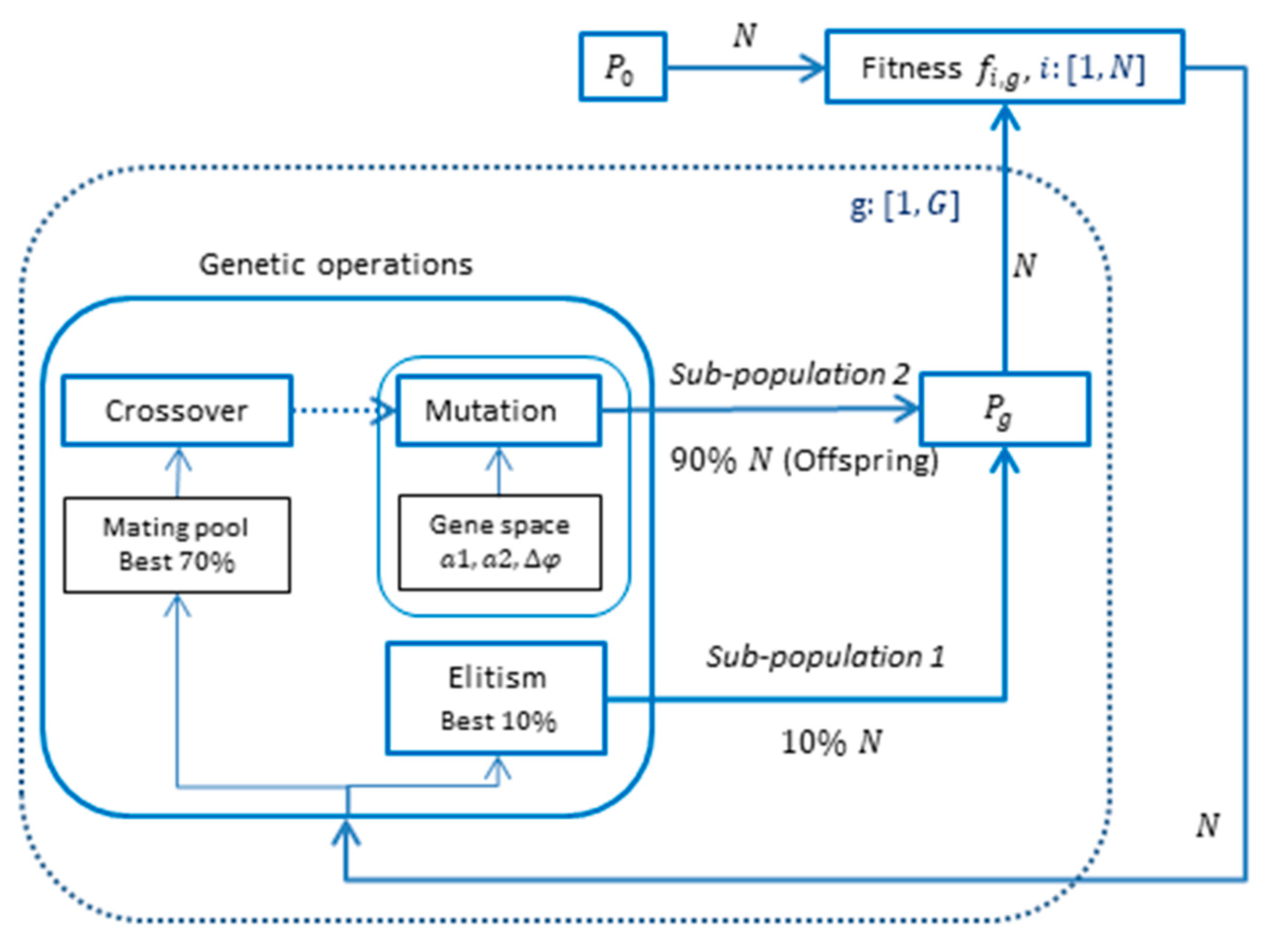
3.1. Genetic Algorithm Consideration

A genetic algorithm searches for the optimal solution of a problem by evolving iteratively generations g using probabilistic transitions, with populations P g , which are sets of candidate solutions. Each solution i , also known as an individual or chromosome, consists of a set of properties, the genes. The algorithm begins with a random population, P 0 . Its convergence speed and computing cost depend on the number of operations, which is a function of the population size N . Each individual is assigned a fitness score, evaluated by a fitness function. The offspring population is created through the genetic operations of selection, crossover, and mutation. The possibility for high-fitness solutions to be lost in the next generations exists, resulting in missing important search information. Elitism [13] ensures the continuing survival of the fittest individuals, by retaining a small portion of the population to carry over unchanged to the next generations. However, this may lead to selective pressure behavior and focus the search exclusively on some good solutions, overlooking other, potentially, fitter ones. Population diversity is a measure of the distribution degree of individuals in the solution space and contributes to making the process less susceptible to being stuck in local optima. A balance between population diversity and selective pressure must be kept, to reach the global optimal point.
The implemented GA is developed in the Python programming language [46] using the “PyGAD” Python package [47]. The proposed control system with the developed compound source is shown in Figure 3. A subwoofer simulates the noise source, operating simultaneously with the control signals. The objective of this strategy is to adapt the compound source radiation and coupling to the modal field through its setup and driving parameters to attenuate the primary field at a selected point. The sequence of the genetic evolution process for the control system is depicted in Figure 4. The GA ends when it reaches the user-defined number of total generations G .

3.2. Coding Scheme

A real-coded GA is used in which each individual is a set of positive real numbers with equal length to the number of the system parameters. The compound control source is a quadrupole configuration; thus, the driving parameters are two numbers for the driving monopole amplitudes of the comprising dipoles and one for their phase difference. These are bounded due to practical limitations, enabling a more effective search for feasible solutions. Therefore, every individual is structured by three genes, { a 1 , a 2 Δ φ }, where:
  • gene1 (dB): amplitude of dipole components 1, a 1 ;
  • gene2 (dB): amplitude of dipole components 2, a 2 ;
  • gene3 (deg): phase difference between dipoles, Δ φ .
The gene values are taken from a defined gene space, which is [ 0.5 ,   9.5 ] , with a 0.5   d B step for a 1 and a 2 , and [ 0 ,   315 ] , with a 45 ° step for Δ φ . The two amplitudes are levels in dB, relative to the initial driving amplitude of the compound source, a c . A difference of a 1 and a 2 higher than 9.5   d B degenerates the quadrupole radiation features. The a c is set so that the secondary sound level at the measurement point is equal to the primary level L n , as first recorded.

3.3. Fitness Evaluation

The fitness function returns a numeric value representing the calculated fitness of each solution, f i , g . It establishes the basis for selecting mating parents during reproduction. In this control system, the objective is to generate quiet zones: the minimization of the primary field using the norm of sound pressure at a discrete point of measurement by utilizing the partial sound destructive interference. The process of selecting the optimal driving parameters is followed each time for a given configuration. The fitness of each individual is assessed as the difference between the existing noise level, L n , and the controlled level after applying the generated i t h driving parameters for the compound source, L i , g :
f i , g = L n L i , g
Therefore, the performance index of noise attenuation is measured based on the direct recording of the combined primary and secondary level, L i , g , which is then subtracted from the measured primary L n to obtain f i , g . The quality of a real-time GA system, with the ability to determine each solution fitness properly, leads to the stable operation and production of fitter scores in subsequent generations. During the system operation, the event of external temporary sound disturbances is probable and may disorientate the evolution convergence. A band-pass finite impulse response (FIR) digital filter design with cutoff frequencies of ± 20   H z around the examined frequency is applied to the microphone input signal. The desired attenuation in the stop band is 60   d B .

3.4. Parent Selection

Several parent selection schemes that emulate the “survival-of-the-fittest” nature mechanism have been proposed, with the prospect to generate better solutions [13]. The rank selection scheme is preferred, as it also serves the concept of elitism. When selecting the parents, the solutions are first ranked based on their fitness, and then the top individuals are used as parents for mating. Individuals from this mating pool produce offspring, and in the next population, the new parents are selected from the top individuals by ranking the solutions of the current parents and offspring. This process terminates when the breeding population has replaced all the old individuals. As shown in Figure 4, the new population consists of two sub-populations. The elitist sub-population 1 is the direct fittest 10% of the current population. The remaining 90%, the offspring sub-population 2, is produced by genetic operations on a mating pool of parents, which are the fittest 70% of the current solutions.

3.5. Genetic Operations of Crossover and Mutation

The basic genetic operations of crossover and mutation create offspring using historical search information and introducing some recombination. Crossover is the principal genetic operator that combines the genes of two parents, resulting in new solutions with intermediate characteristics. Since each chromosome consists of three genes, the single point type is applied with a random crossover point on the genes of both parents. After the GA tuning, the crossover probability parameter p c at a particular mating is set to 0.75 for a good balance between population diversity and selective pressure.
In the mutation process, some genes are changed randomly from the gene space obtaining new solutions. The mutation rate is given a small probability, i.e., p m = 0.15 , to prevent the irreversible loss of important information for the search progress. Mutation is a way of avoiding premature convergence to local optima. Although it is used less frequently, as its random nature is more likely to degrade a good chromosome than improve it, it contributes to population diversity.
The adaptive mutation is also used for further investigations of the GA operation and comparison purposes. Instead of using a constant rate, adaptive mutation replaces strings of low fitness with higher probability. The offspring produced from crossover does not directly undergo mutation, but first take part in a temporary population along with the parents from elitism, to complete N individuals. The average fitness f g is calculated from this intermediate population, and each solution is determined for low or high mutation probability according to its fitness. This helps to avoid the total randomness of mutation applied equally to all chromosomes. Therefore, the fitness of the good solutions is maintained, and that of the weaker ones may be increased. Two values are given in adaptive mutation: the first is the mutation rate for the low-quality solutions and the second is for the high-quality ones : [ p l o w , p h i g h ] . The adaptive mutation works as follows [47]:
Calculation of the population’s average fitness, f g . For each individual:
If f i , g < f g , it is regarded as a low-quality solution, so the mutation rate is high in order to improve its quality.
If f i , g f g , it is regarded as a high-quality solution, so the mutation rate is low in order to avoid disrupting its quality.

3.6. GA Parameters Selection

A crucial factor that determines GA effectiveness is the tuning of the parameters and the genetic operations. The population size is chosen to be sufficiently big in order to fulfill the population diversity. After several experimental tests for this ANC implementation, proper GA performance is obtained using 40 individuals, along with the genetic parameters in Table 1.

4. Measurement Strategy and Equipment

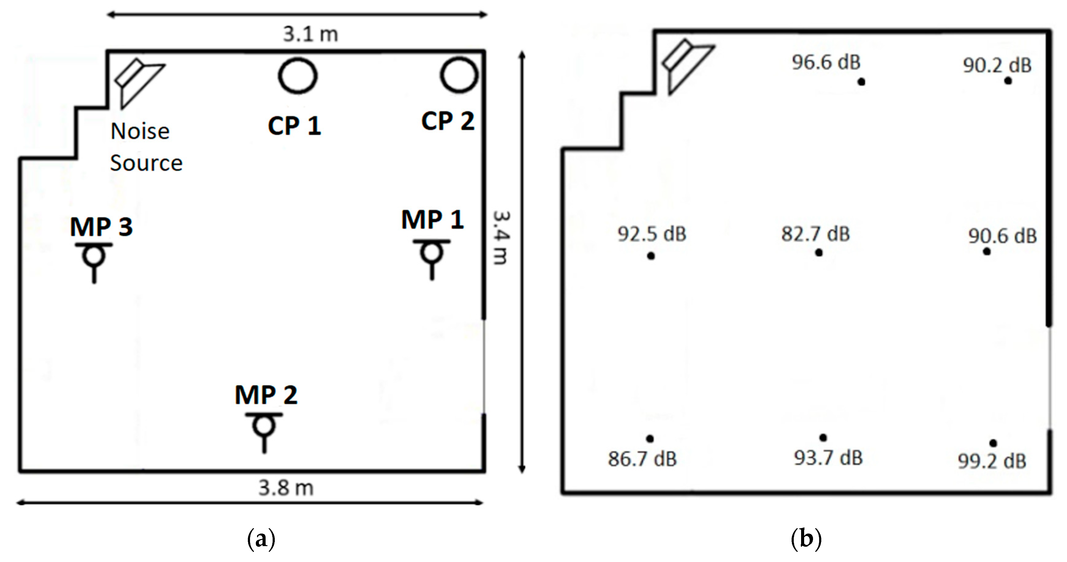
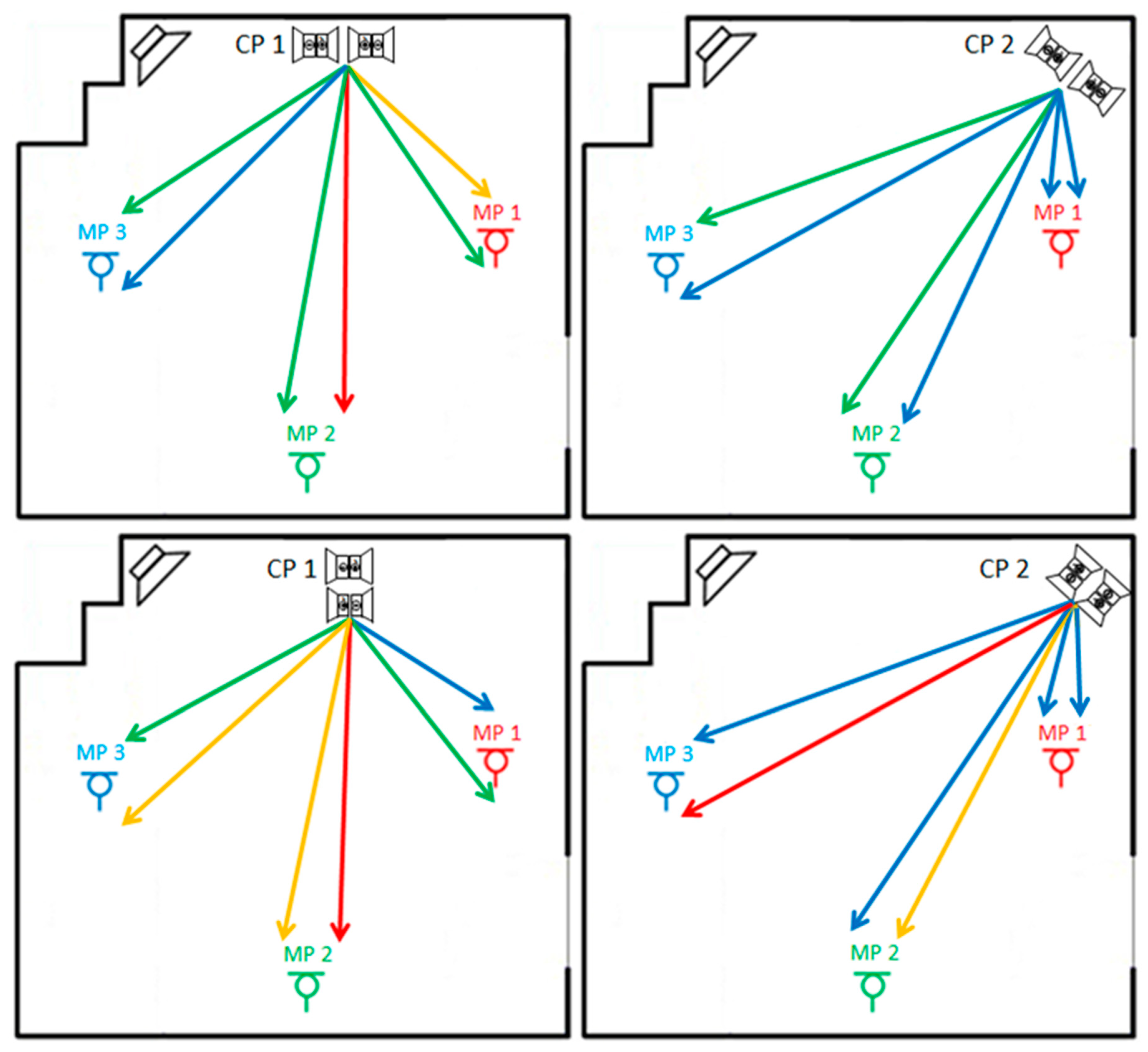
4.1. Investigated Room and Sources Configuration

The room for the noise control investigations is in our laboratory and has an approximate volume of 33   m 3 and a floor area of 12   m 2 . There is a suspended ceiling of acoustic tiles at a distance of 0.25   m from the concrete to drive the ventilation ducts. Perforated panels backed by thick absorbing material cover the side walls. Three areas are targeted to create quiet zones at the measurement points (MP). Regarding the control positions, there are no other options than placing the compound source in two vacant areas: at a corner or along the edge between the floor and the wall. The floor dimensions of 3.8   m × 3.4   m × 3.1   m , height of 2.8   m , MP at a height of 1.2   m , and the control positions are depicted in Figure 5a.
In the following experiments, the first axial modes cannot be derived directly due to the room shape. These could be a guideline to orientate the quadrupoles to the direction of modes. The dominant frequencies are measured with a low-frequency logarithmic sine sweep in each MP, as seen in Figure 6. The frequency of 50   H z is the most dominant in the three points. For this frequency, the sound pressure level at eight points was acquired using an NTI XL 2 Audio analyzer and is depicted in Figure 5b to show that no axial mode is profound in the two main axes. For each area, the two most dominant frequencies are considered for attenuation. Therefore, along with the frequency of 50   H z , noise control should be also implemented for the frequencies of 100   H z at MP 1, 77   H z at MP 2, and 108   H z at MP 3 (Figure 6). Due to the long wavelengths of the investigated frequencies, i.e., ~ 3.2 6.8   m , one error microphone is sufficient for investigating quiet indoor working zones. For each dipole source, d = 20   c m . For the longitudinal source, the distance between the acoustic centers of the dipoles is D = 55   c m , while for the lateral it is 20   c m . Thus, it applies d < < λ for the shortest investigated wavelength of ~ 3.18   m   ( 108   H z ) .

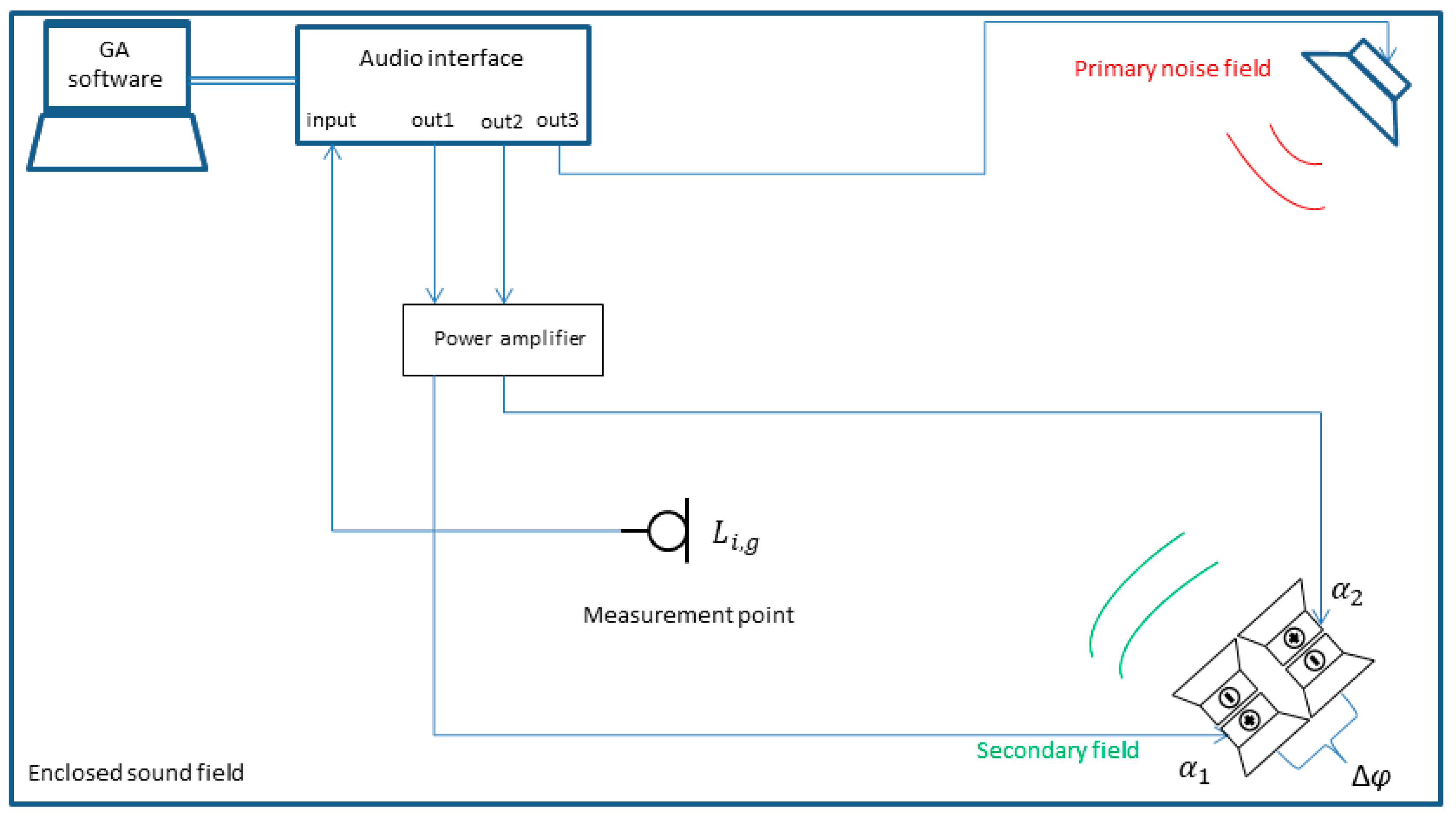
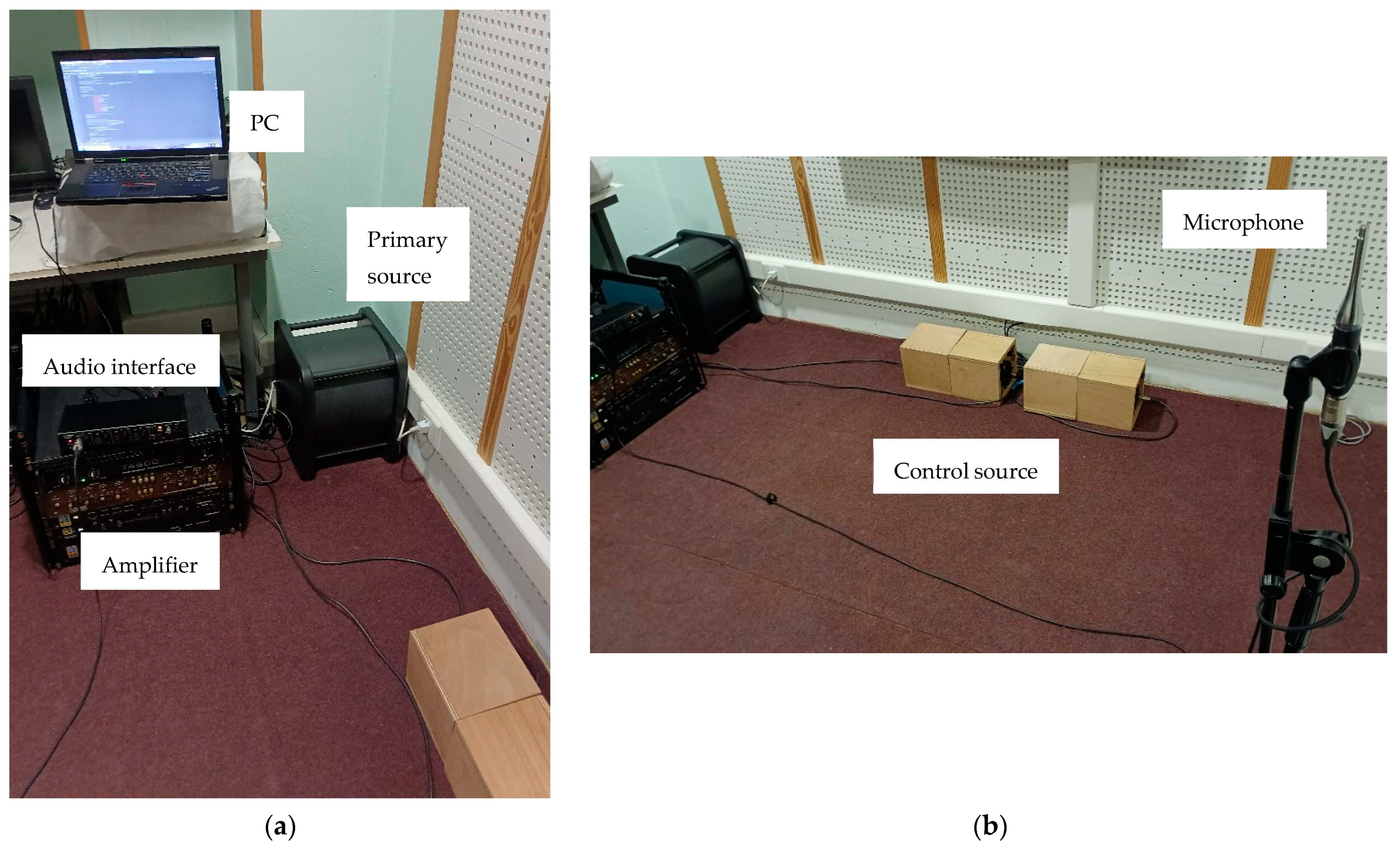
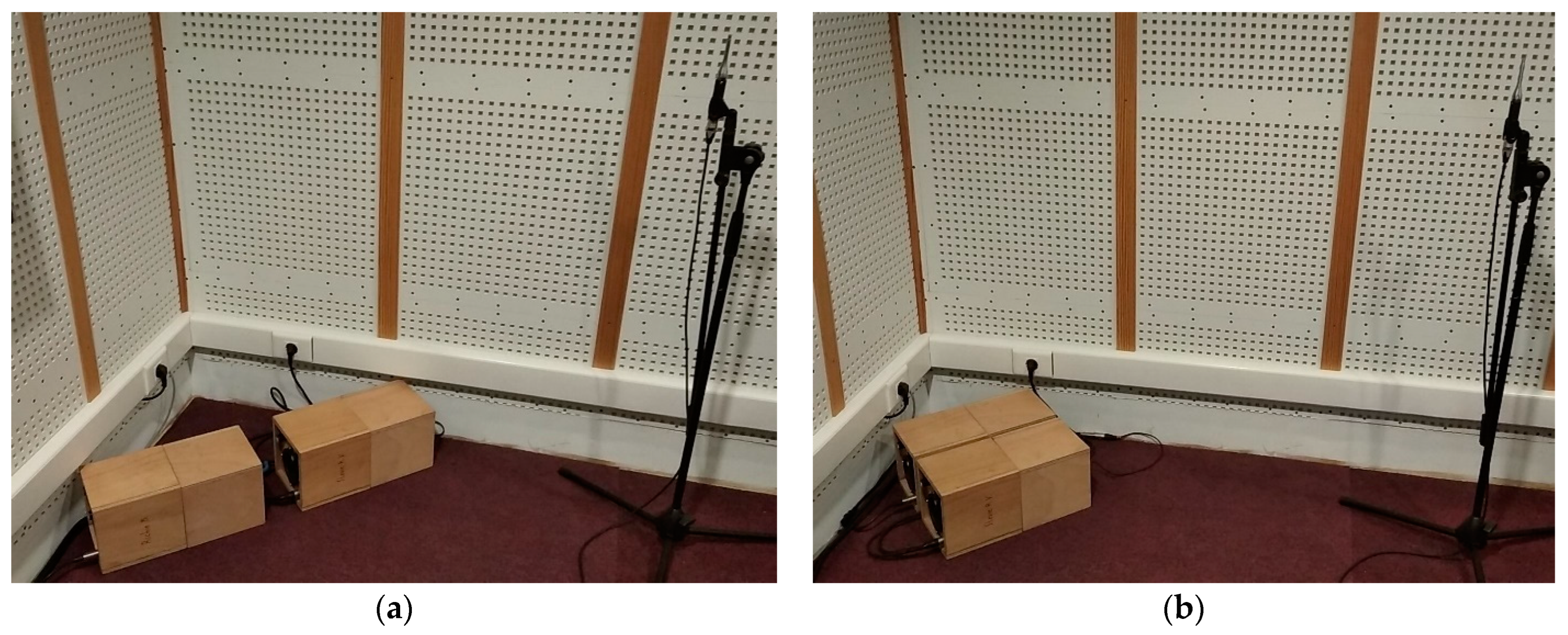
4.2. Equipment of the ANC Experiments

The strategy proposed in Section 3.1 was tested with the experimental setup shown in Figure 7. With the measurement microphone positioned at one out of three investigated points, as shown in Figure 7b, the setup corresponds to the wire connection diagram for the experiments (Figure 3).
Each monopole source, with outer dimensions of 20   c m × 18.5   c m × 18.5   c m , includes a 4″ ( = 101.6   m m , 4   O h m ) Visaton (Haan, Germany) KT 100 V driver with low resonance frequency, f S = 37   H z , and low force factor, B l = 3.43   T · m , in an optimal bass-reflex box design [25]. The developed lightweight subwoofers were arranged in two quadrupole configurations for noise control (Figure 8). A computer was used with the developed software to drive the compound source into a Thomann (Burgebrach, Germany) The t.amp TA 600 MK-X 2-channel audio power amplifier, with each channel dedicated to a single dipole. The signal is reversed by 180 ° before the input to the second monopole. An active subwoofer loudspeaker system Genelec (Iisalmi, Finland) 7360 APM was driven by a third channel to simulate the primary source. The omnidirectional NTI Audio (Schaan, Liechtenstein) M4260 measurement microphone was used, positioned at the head height of the listener, z = 1.2   m . A four-channel, high-resolution USB audio interface, Tascam (Santa Fe Springs, CA, USA) US-4x4HR, was used for connection between the sound equipment and software.

5. Experimental Results and Discussion
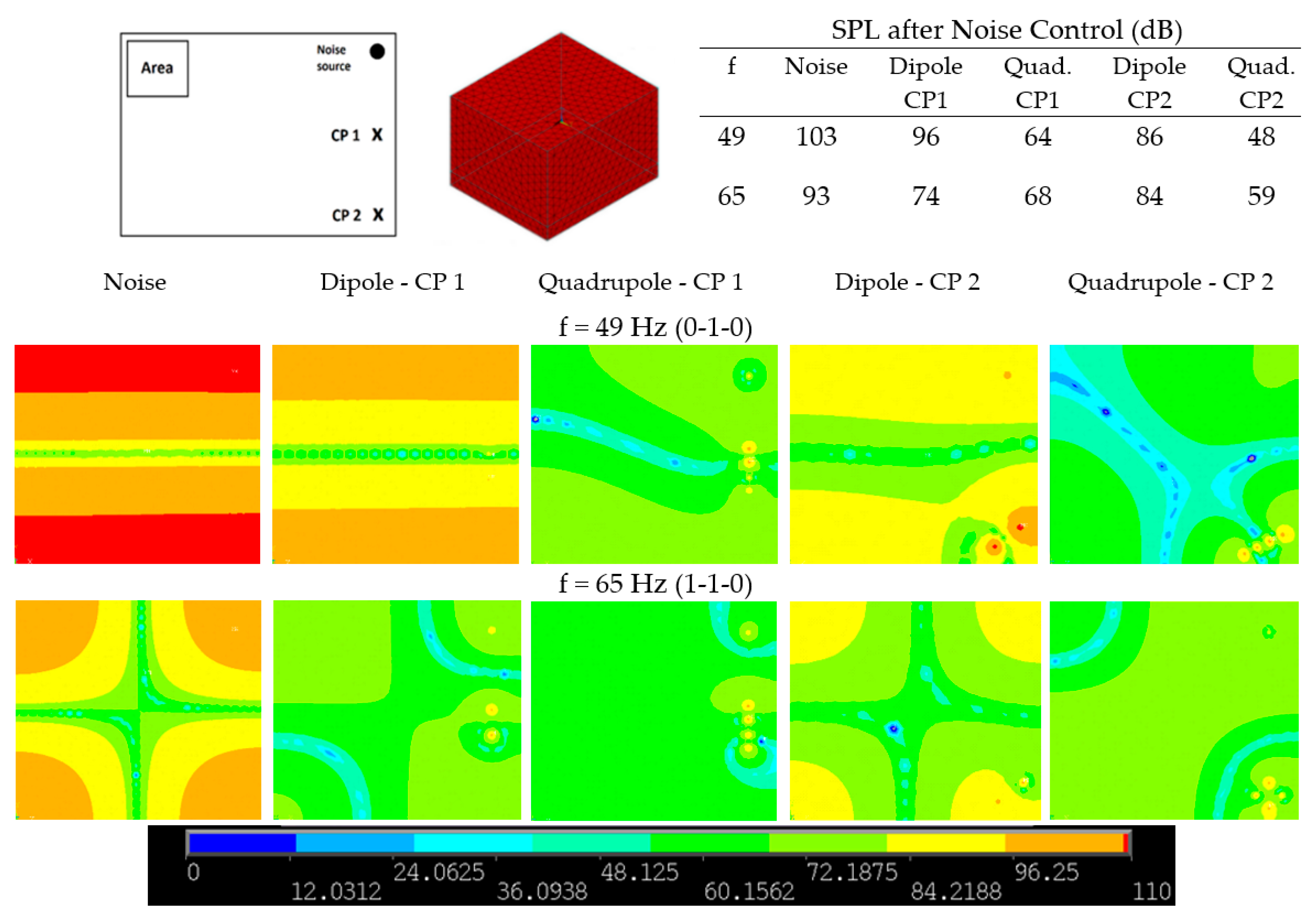
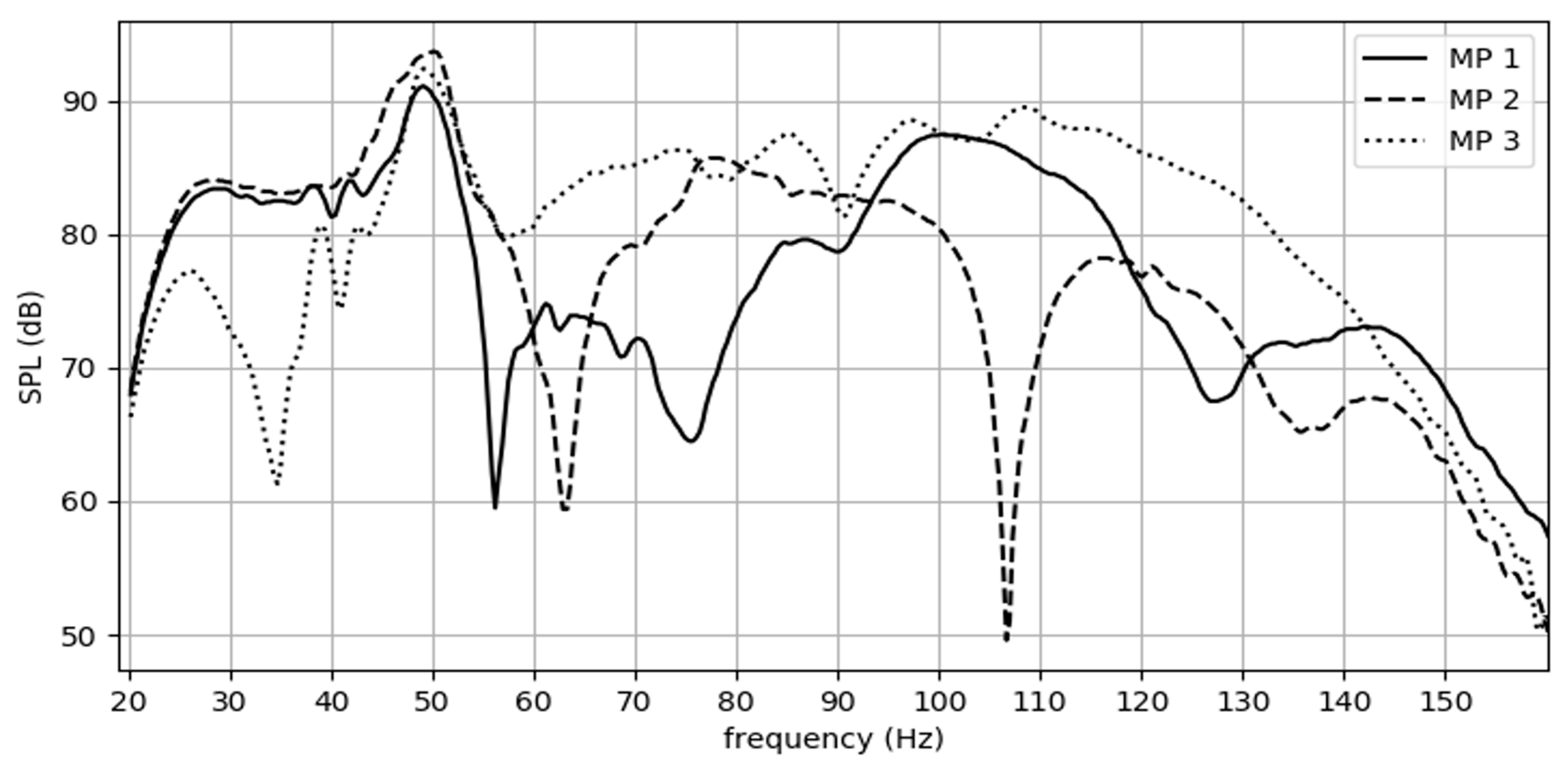
5.1. Results

The developed system was tested several times with the two quadrupoles placed at the two control positions. Among these experiments, the two optimal configurations for each dominant frequency are presented. The corresponding maximum noise reduction and optimal driving parameters for the longitudinal (Long) and the lateral (Lat) quadrupole setup are shown in Table 2.
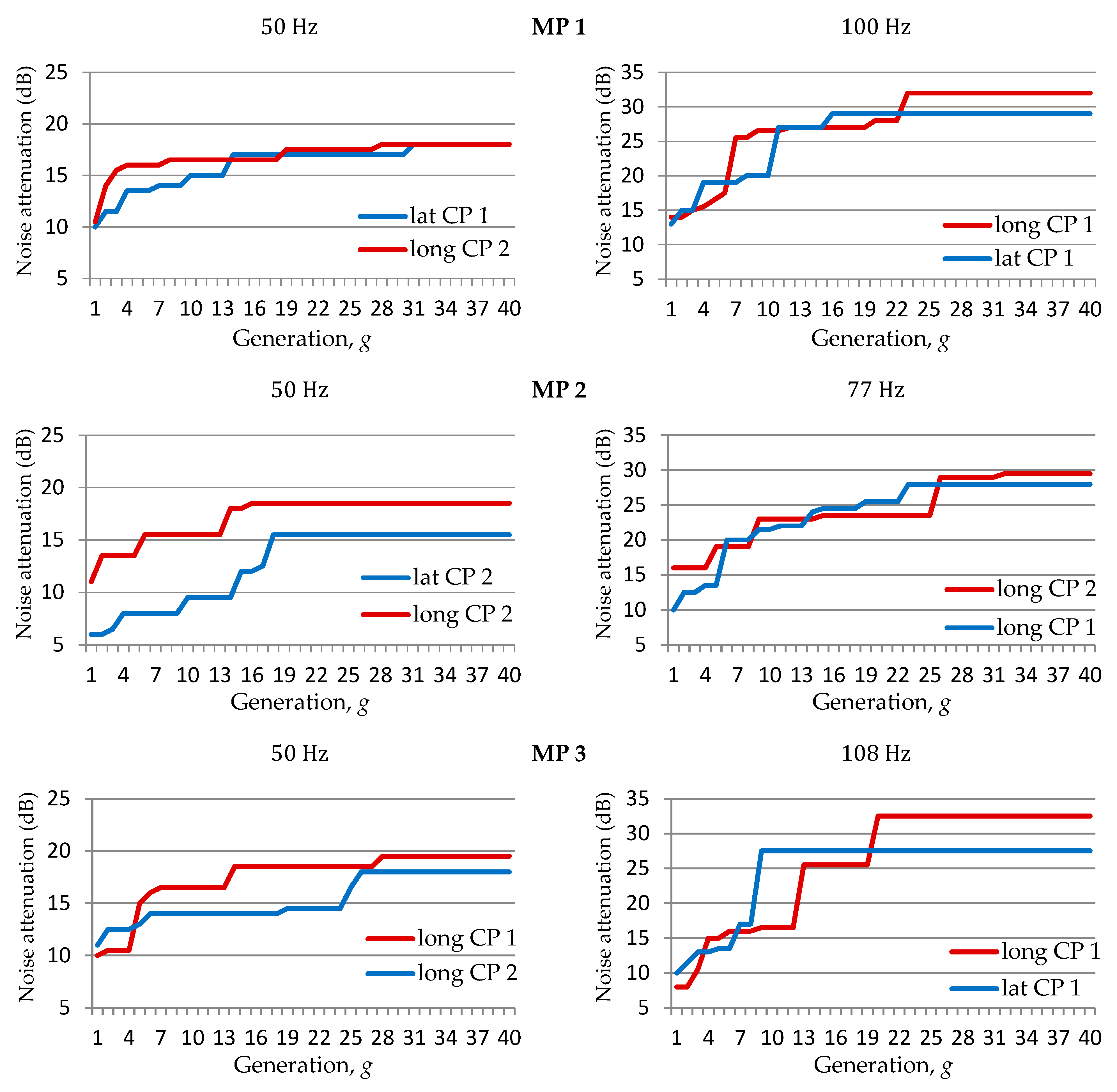
MP 1: From Table 2, it seems that both quadrupoles offer the same maximum attenuation at 50   Hz when they are positioned at CP 2 and CP 1, respectively. At 100   H z , the attenuation is much higher, reaching 32   d B , and the longitudinal prevails slightly over the lateral source, giving a 3   d B higher maximum attenuation.
MP 2: At 50   Hz , the longitudinal quadrupole at CP 2 attains a quite satisfying attenuation of 18.5   d B , while the lateral source at the same position achieves a reduction of 15.5   d B . At 77   H z , the longitudinal quadrupole offers noise attenuation up to 29.5   d B , in which CP 2 has the advantage over CP 1.
MP 3: At 50   Hz , the longitudinal quadrupole at CP 1 offers high primary attenuation of 19.5   d B . At 108   H z , it reaches a reduction of 32.5   d B at the same position. Again, the longitudinal source offers higher attenuation at both frequencies.
In Table 3, the optimal attenuation results are given for the two control setups in each CP, MP, and frequency. Ιn Figure 9, the same results are depicted with colored arrows to show the noise control efficiency between each pair of CP and MP. The results are divided into four groups: red color is used for noise attenuation of up to 8   d B (“not sufficient”), orange for up to 16   d B (“sufficient”), blue for up to 24   d B (“satisfying”), and green for higher reduction levels (“very satisfying”).
Ιt is derived that the dominant frequencies can be controlled sufficiently in every MP by using either the longitudinal or the lateral configuration. The longitudinal source can at least satisfyingly control all the problematic frequencies in each MP, especially when it is positioned in CP 2. This does not stand for the lateral source. Specifically, at CP 1, noise control is not sufficient at 50   H z in MP 2 ( 6   d B ), while it is slightly sufficient in MP 3 ( 8.5   d B ). With the lateral source at CP 2, the attenuation at the same frequency is not sufficient in MP 3 ( 6.5   d B ), while it is sufficient in MP 2 ( 15.5   d B ). The same setup offers a reduction of 18.5   d B at 77   H z in MP 2. Although this is satisfying, it is far less than the maximum attained attenuation with the longitudinal source at the same position ( 29.5   d B ). For the higher frequencies of 100   H z and 108   H z faced in MP 1 and MP 3, the longitudinal source at CP 1 attains the highest attenuation of 32 and 32.5   d B , respectively. In Figure 10, the genetic evolution with random mutation for the primary field attenuation at each MP and frequency is depicted for the two optimal cases, as presented in Table 2.
As far as investigations in the GA operation are concerned, the evolution is also tested using adaptive mutation ( [ p l o w , p h i g h ] : [ 0.3 , 0.1 ] ) . The genetic evolution for each case is depicted in Figure 11, along with the corresponding one from Figure 10 for comparison purposes. It is shown that the optimal results given in Table 2 not only can be reached but this is also achieved in earlier generations. This is expected, as the adaptive mutation replaces strings of low fitness with higher probability and drives to selective pressure; thus, fitter solutions tend to appear in earlier generations. The optimal results of the genetic evolution with the adaptive mutation are given in Table 4.
The Δ φ is an important degree of freedom. Various steps of 45 ° seem to offer a significant contribution in searching for successful noise attenuation. The third gene has a crucial role in the fitness score, as solution sets with the same Δ φ and close first and second genes can obtain the same score, i.e., { 3.5 , 3 , 90 } = { 3.5 , 2.5 , 90 } = 32 , while individuals with the same first two genes and different Δ φ may have far different scores, i.e., 3.5 , 3 , 90 { 3.5 , 3 , 315 } = 3.5 , resulting in noise reinforcement. Therefore, while some of the optimal driving parameters in Table 4 slightly differ in some a1 and a2, they produce the same fitness with the corresponding results in Table 2. In any case, the optimal Δ φ value remains the same, with either random or adaptive mutation.

5.2. Discussion

While various orientations of the two quadrupole topologies were examined, especially in CP 2, the presented ones are the most effective. The concept was to set the compound source in a location to occupy the least possible space and to control the noise frequencies at all points. By inspecting Table 3, control of different frequencies and areas can be attained by the compound source in a fixed position thanks to its radiation coupling with the room modal field. If one control position suppresses a disturbing frequency, the same can be sufficient for attenuating another frequency. This is achieved via the driving signals; thus, there is no need to relocate the source. There is also no requirement for a specific compound layout for successful performance, as the source will adapt itself to the position.
In addition, the engineering perception indicates where the sources must be placed to efficiently control the noise field in combination with the limited available space in an equipped room. The presented system surpasses the space constraints as it can control different frequencies without distributing secondary sources. Furthermore, if a convenient location is no longer available, an alternative one can be chosen, and the GA produces a set of optimal solutions for the driving parameters with a similar amount of noise attenuation, as has been shown for most cases in Table 2.
In the experiments, the longitudinal source offers a fine solution for noise control in the low-frequency range, as it prevails over the lateral type in almost all cases. Considering that these sources operate at low frequencies in a room rather than in the free field, the coupling degree of sound pressure distribution is higher for the longitudinal case.
The low-frequency radiation from small sources is inefficient; therefore, the use of low- B l drivers offers a fine solution for the development of low-volume subwoofer compound sources. The maximum attenuation for the frequency of 50   H z that is obtained in all measurement points is not as high as it is for the higher frequencies of 77 , 100 , and 108   H z . This is probably due to limited power output at 50   H z , compared to higher frequencies, as was observed when designing the low- B l loudspeakers [25]. Although the attained amount of reduction is quite sufficient for such a low frequency, more source strength may be required for possible higher attenuation by designing more powerful low- B l subwoofers. This may be done at the expense of the volume of each secondary monopole, but the concept of this work is beneficial to this direction.
It is noticed that the maximum noise reduction is 20   d B when placing the longitudinal quadrupole at CP 1 to reduce the 50   H z component at MP 3, in Table 4. However, the corresponding value is 19.5   d B in Table 2. In sound level measurements, we obtain pressure fluctuations, and therefore, the same driving parameters may produce fitness score differences within 0.5   d B in subsequent measurements, which are meaningless and not audibly distinctive to the human ear.
Regarding the GA performance, it is expected that the process converges in a population dominated by the optimal solution of the fitness function. This provides the opportunity to choose the most convenient set for each case among several near-global solutions that may offer an overall reduction at the microphone, which is within 0.5 1   d B of the optimal one, as presented in Figure 12. The system robustness was tested with experiments of five consecutive genetic evolutions for the case of MP 2 at 77   H z and the longitudinal source at CP 2, each with a different initial population of the same length. Despite the slight differences, all five cases converge in the same vicinity and attain primary field attenuation within ± 0.5   d B of the maximum reduction level of 29.5   d B , showing consistency in the optimal result. Another advantage is that there is no need for a reference signal or correlation with the error signal. The proposed ANC system is independent of transfer functions between sources and error sensors.
In this work, every solution constitutes a single measurement with a duration of ~ 3 s; thus, the whole optimization procedure may take several minutes to complete. Nevertheless, this is only what it takes to face and suppress an annoying low-frequency tone for a single source configuration. In the case that the noise tone shifts, which is not met often in industrial equipment operating at a steady cycle rate, then the compound setup can suppress it with a new genetic evolution. It is worth mentioning that adaptive mutation proves to be quite helpful in reducing the experimental duration, as it can reach the optimal result in earlier generations. In the experiments, one generation with 40 individuals could last ~ 2 min. From Figure 11, it is observed that 20 generations are enough to reach the optimal attenuation using adaptive mutation.

6. Conclusions

In the present study, a novel approach for low-frequency noise attenuation in modal fields using genetic algorithm optimization is addressed. The proposed method can successfully control a modal primary field with a compound source at a single fixed position, for different frequencies, and at multiple listening positions. The longitudinal quadrupole located at CP 2 can control all the problematic frequencies in all positions at least satisfyingly. The secondary field is produced by the adaptable radiation of the compound source and, therefore, the developed low-volume low- B l loudspeakers are quite promising in noise control, contributing to the formation of small secondary sources in limited spaces. The experiments show that topologies such as the longitudinal quadrupoles can offer better control. The control ability of each mode frequency has a limited dependence on the combination of the compound source configuration with its position in the room. The present study faces the control of a single noise frequency, simulating an operating industrial machine. Future work may be expanded to study the system robustness in the control of multiple resonance frequencies.
The overall performance of the proposed system is evaluated as quite satisfying, in combination with the self-adaptation and single-position characteristics of the secondary source. The presented results validate the integrated ANC system, which provides an effective and flexible alternative solution to the existing control systems in dealing with low-frequency attenuation in enclosed sound fields.

Author Contributions

Conceptualization, M.G.; methodology, C.S.; software, M.G.; validation, C.S.; formal analysis, M.G. and C.S.; investigation, M.G. and C.S.; resources, G.P.; data curation, M.G.; writing—original draft preparation, M.G.; writing—review and editing, M.G. and C.S.; supervision, G.P.; project administration, G.P. All authors have read and agreed to the published version of the manuscript.

Funding

This research received no external funding.

Institutional Review Board Statement

The study did not require ethical approval.

Informed Consent Statement

Not applicable.

Data Availability Statement

The code for reproducing the experiments is available at a dedicated online repository https://github.com/MariosGiouv/GA-LF-ANC-CompoundSources.git (accessed on 26 April 2023).

Conflicts of Interest

The authors declare no conflict of interest.

References

  1. Lueg, P. Process of Silencing Sound Oscillations. U.S. Patent 2043416, 9 June 1936. [Google Scholar]
  2. Elliott, S. Signal Processing for Active Control; Elsevier: Amsterdam, The Netherlands, 2000. [Google Scholar]
  3. Zhang, J.; Elliott, S.J.; Cheer, J. Robust Performance of Virtual Sensing Methods for Active Noise Control. Mech. Syst. Signal Process. 2021, 152, 107453. [Google Scholar] [CrossRef]
  4. Libianchi, P.; Brunskog, J.; Agerkvist, F.; Shabalina, E. Active Noise Control at Low Frequencies for Outdoor Live Music Events Using the Conjugate Gradient Least Square Method. Appl. Acoust. 2023, 205, 109235. [Google Scholar] [CrossRef]
  5. Wang, S.; Yu, J.; Qiu, X.; Pawelczyk, M.; Shaid, A.; Wang, L. Active Sound Radiation Control with Secondary Sources at the Edge of the Opening. Appl. Acoust. 2017, 117, 173–179. [Google Scholar] [CrossRef]
  6. Lam, B.; Shi, D.; Belyi, V.; Wen, S.; Gan, W.S.; Li, K.; Lee, I. Active Control of Low-Frequency Noise through a Single Top-Hung Window in a Full-Sized Room. Appl. Sci. 2020, 10, 6817. [Google Scholar] [CrossRef]
  7. Ha, S.; Kim, J.; Kim, H.-G.; Wang, S. Horizontal Active Noise Control Based on Wave Field Reproduction Using a Single Circular Array in 3D Space. Appl. Sci. 2022, 12, 10245. [Google Scholar] [CrossRef]
  8. Jiang, T.; Liu, J.; Peng, C.; Wang, S. Laboratory Test of a Vehicle Active Noise-Control System Based on an Adaptive Step Size Algorithm. Appl. Sci. 2023, 13, 225. [Google Scholar] [CrossRef]
  9. Zhang, S.; Zhang, L.; Meng, D.; Pi, X. Active Control of Vehicle Interior Engine Noise Using a Multi-Channel Delayed Adaptive Notch Algorithm Based on FxLMS Structure. Mech. Syst. Signal Process. 2023, 186, 109831. [Google Scholar] [CrossRef]
  10. Sun, M.; Lu, C.; Liu, Z.; Chen, W.; Shen, C.; Chen, H. A New Feedforward and Feedback Hybrid Active Noise Control System for Excavator Interior Noise. Appl. Acoust. 2022, 197, 108872. [Google Scholar] [CrossRef]
  11. Lu, L.; Yin, K.L.; de Lamare, R.C.; Zheng, Z.; Yu, Y.; Yang, X.; Chen, B. A Survey on Active Noise Control in the Past Decade–Part I: Linear Systems. Signal Process. 2021, 183, 108039. [Google Scholar] [CrossRef]
  12. Lu, L.; Yin, K.L.; de Lamare, R.C.; Zheng, Z.; Yu, Y.; Yang, X.; Chen, B. A Survey on Active Noise Control in the Past Decade–II: Nonlinear Systems. Signal Process. 2021, 181, 107929. [Google Scholar] [CrossRef]
  13. Goldberg, D.E. Genetic Algorithm in Search, Optimization and Machine Learning; Addison-Wesley Longman Publishing Co., Inc.: New York, NY, USA, 1989. [Google Scholar]
  14. Wangler, C.T.; Hansen, C.H. Genetic Algorithm Adaptation of Non-Linear Filter Structures for Active Sound and Vibration Control. In Proceedings of the ICASSP’94, IEEE International Conference on Acoustics, Speech and Signal Processing, Adelaide, SA, Australia, 19–22 April 1994; Volume 3, pp. 505–508. [Google Scholar]
  15. Tang, K.S.; Man, K.F.; Kwong, S.; He, Q. Genetic Algorithms and their Applications. IEEE Signal Process. Mag. 1996, 13, 22–37. [Google Scholar] [CrossRef]
  16. Simpson, M.T.; Hansen, C.H. Use of Genetic Algorithms to Optimize Vibration Actuator Placement for Active Control of Harmonic Interior Noise in a Cylinder with Floor Structure. Noise Control Eng. J. 1996, 44, 169–184. [Google Scholar] [CrossRef]
  17. Diamantis, Z.; Tsahalis, D.; Borchers, I. Optimization of an Active Noise Control System Inside an Aircraft, Based on the Simultaneous Optimal Positioning of Microphones and Speakers, with the Use of a Genetic Algorithm. Comput. Optim. Appl. 2002, 23, 65–76. [Google Scholar] [CrossRef]
  18. Baek, K.H.; Elliott, S.J. Natural Algorithms for Choosing Source Locations in Active Control Systems. J. Sound Vib. 1995, 186, 245–267. [Google Scholar] [CrossRef]
  19. Makarewicz, G. Application of Genetic Algorithm in an Active Noise Control System. Arch. Acoust. 2007, 32, 839–849. [Google Scholar]
  20. Martin, T.; Roure, A. Active Noise Control of Acoustic Sources Using Spherical Harmonic Expansion and a Genetic Algorithm: Simulation and Experiment. J. Sound Vib. 1998, 212, 511–523. [Google Scholar] [CrossRef]
  21. Montazeri, A.; Poshtan, J. GA-based Optimization of a MIMO ANC System Considering Coupling of Secondary Sources in a Telephone Kiosk. Appl. Acoust. 2009, 70, 945–953. [Google Scholar] [CrossRef]
  22. Long, G.; Wang, Y.; Lim, T. Optimal Parametric Design of Delayless Subband Active Noise Control System Based on Genetic Algorithm Optimization. J. Vib. Control 2021, 28, 1950–1961. [Google Scholar] [CrossRef]
  23. Giouvanakis, M.; Sevastiadis, C.; Vrysis, L.; Papanikolaou, G. Control of Resonant Low-Frequency Noise Simulations in Different Areas of Small Spaces Using Compound Source. In Proceedings of the Euronoise Conference, Crete, Greece, 27–31 May 2018. [Google Scholar]
  24. Giouvanakis, M.; Sevastiadis, C.; Papanikolaou, G. Low-Frequency Noise Attenuation in a Closed Space using Adaptive Directivity Control Sources of a Quadrupole Type. Arch. Acoust. 2019, 44, 71–78. [Google Scholar] [CrossRef]
  25. Giouvanakis, M.; Kasidakis, K.; Sevastiadis, C.; Papanikolaou, G. Design and Construction of Loudspeakers with Low-Bl Drivers for Low-Frequency Active Noise Control Applications. In Proceedings of the 23rd ICA, Aachen, Germany, 9–13 September 2019. [Google Scholar]
  26. Giouvanakis, M.; Sevastiadis, C.; Papanikolaou, G. Measurement of Compound Sound Sources with Adaptive Spatial Radiation for Low-Frequency Active Noise Control Applications. Arch. Acoust. 2021, 46, 205–212. [Google Scholar] [CrossRef]
  27. Bullmore, A.J.; Nelson, P.A.; Curtis, A.R.D.; Elliott, S.J. The Active Minimization of Harmonic Enclosed Sound Fields, Part II: A Computer Simulation. J. Sound Vib. 1987, 117, 15–33. [Google Scholar] [CrossRef]
  28. Aarts, R.O.M. High-Efficiency Low-Bl Loudspeakers. J. Audio Eng. Soc. 2005, 53, 579–592. [Google Scholar]
  29. Altanis, T.; Mourjopoulos, J. Analysis of Low Frequency Audio Reproduction via Multiple Low-Bl Loudspeakers. In Proceedings of the 128th Convention of the Audio Engineering Society, London, UK, 22–25 May 2010. [Google Scholar]
  30. Olson, H.F. Gradient Loudspeakers. J. Audio Eng. Soc. 1973, 21, 86–93. [Google Scholar] [CrossRef]
  31. Hill, A.J.; Hawksford, M.O.J. Chameleon Subwoofer Arrays—Generalized Theory of Vectored Sources in a Closed Acoustic Space. In Proceedings of the 128th Convention of the Audio Engineering Society, London, UK, 22–25 May 2010. [Google Scholar]
  32. Kido, K. The technologies for active noise control. J. Acoust. Soc. Jpn. 1991, 12, 245–253. [Google Scholar] [CrossRef]
  33. Wang, S.; Sun, H.; Pan, J.; Qiu, X. Near-Field Error Sensing for Active Directivity Control of Radiated Sound. J. Acoust. Soc. Am. 2018, 144, 598–607. [Google Scholar] [CrossRef]
  34. Bolton, J.S.; Gardner, B.K.; Beauvilain, T.A. Sound Cancellation by the Use of Secondary Multipoles. J. Acoust. Soc. Am. 1995, 98, 2343–2362. [Google Scholar] [CrossRef]
  35. Qiu, X.; Hansen, C.H. Secondary Acoustic Source Types for Active Noise Control in Free Field: Monopoles or Multipoles? J. Sound Vib. 2000, 232, 1005–1009. [Google Scholar] [CrossRef]
  36. Chen, W.; Pu, H.; Qiu, X. A Compound Secondary Source for Active Noise Radiation Control. Appl. Acoust. 2010, 71, 101–106. [Google Scholar] [CrossRef]
  37. Norton, M.P.; Karczub, D.G. Fundamentals of Noise and Vibration Analysis for Engineers, 3rd ed.; Cambridge University Press: Cambridge, UK, 2003; pp. 162–164. [Google Scholar]
  38. Boodoo, S.; Paurobally, R.; Bissessur, Y. A Review of the Effect of Reflective Surfaces on Power Output of Sound Sources and on Actively Created Quiet Zones. Acta Acust. United Acust. 2015, 101, 877–891. [Google Scholar] [CrossRef]
  39. Borwick, J. Loudspeaker and Headphone Handbook, 3rd ed.; Focal Press: Oxford, UK, 2001. [Google Scholar]
  40. Tao, J.; Wang, S.; Qiu, X.; Pan, J. Performance of a Multichannel Active Sound Radiation Control System Near a Reflecting Surface. Appl. Acoust. 2017, 123, 1–8. [Google Scholar] [CrossRef]
  41. Ferekidis, C.; Kempe, U. Room Mode Excitation of Dipolar and Monopolar Low Frequency Sources. In Proceedings of the 100th Convention of the Audio Engineering Society, Copenhagen, Denmark, 11–14 May 1996. [Google Scholar]
  42. Russell, D.A.; Titlow, J.P.; Bemmen, Y.J. Acoustic Monopoles, Dipoles, and Quadrupoles: An Experiment Revisited. Am. J. Phys. 1999, 67, 660–664. [Google Scholar] [CrossRef]
  43. Beranek, L.L. Acoustics; Bolt Beranek and Newman Inc.: Cambridge, MA, USA, 1996. [Google Scholar]
  44. Prinn, A.G. A Review of Finite Element Methods for Room Acoustics. Acoustics 2023, 5, 367–395. [Google Scholar] [CrossRef]
  45. Istvan, L.V.; Beranek, L.L. Noise and Vibration Control Engineering Principles and Applications, 2nd ed.; John Wiley & Sons: Hoboken, NJ, USA, 2006; pp. 145–150. [Google Scholar]
  46. Rossum, G.V.; Drake, F.L. Python 3 Reference Manual; CreateSpace: Scotts Valley, CA, USA, 2009. [Google Scholar]
  47. Gad, A.F. PyGAD: An Intuitive Genetic Algorithm Python Library. arXiv 2021, arXiv:2106.06158. [Google Scholar] [CrossRef]
Figure 1. Compound sources, with d as the distance between the two poles of a dipole component, D as the distance between the dipoles, and the encircled minus and plus symbols determining the 180 ° phase difference of the dipole components. (a) Longitudinal and (b) lateral quadrupole.
Applsci 13 06740 g001
Figure 2. Sound pressure level (SPL) mappings (dB) in a finite element model with the attenuation results. First column: noise field from a point source in the upper right corner at 49 (first row) and 65   H z (second row). Control with a dipole at control position (CP) 1 (second column), a quadrupole at CP 1 (third column), a dipole at CP 2 (fourth column), a longitudinal ( 49   H z ), and a lateral quadrupole ( 65   H z ) at CP 2 (fifth column).
Applsci 13 06740 g002
Figure 3. The control system with a compound source. L i , g is the primary field L n combined with the secondary field, a 1 a 2 are the driving amplitudes of each dipole, and Δ φ is their phase difference.
Applsci 13 06740 g003
Figure 4. Genetic evolution process of the control system.
Applsci 13 06740 g004
Figure 5. (a) Room schematic diagram with the positions of interest. (b) Noise level at eight points for the frequency of 50   H z at the measurement height of 1.2   m .
Applsci 13 06740 g005
Figure 6. Noise level for the three areas in the low-frequency range.
Applsci 13 06740 g006
Figure 7. The equipment for the ANC experiments: (a) noise source, audio amplifier, sound card, and computer; (b) compound source at control position (CP) 1, and microphone at measurement point (MP) 1.
Applsci 13 06740 g007
Figure 8. The investigated room with the compound control source located at CP 2 and the microphone at MP 1: (a) longitudinal and (b) lateral setup.
Applsci 13 06740 g008
Figure 9. Optimal noise attenuation among each CP, MP, and frequency. For each MP, the first arrow represents the 50   H z case, while inspecting the graph in a clockwise direction. Τhe second arrow is for 100   H z (MP 1), 77   H z (MP 2), and 108   H z (MP 3).
Applsci 13 06740 g009
Figure 10. Evolution of noise attenuation for the two best cases of each MP and frequency.
Applsci 13 06740 g010
Figure 11. Evolution of noise attenuation for the best case of each MP and frequency, with random (red) and adaptive (green) mutation.
Applsci 13 06740 g011
Figure 12. Consecutive experiments with different initial populations on attenuation at 77   H z in MP 2 with the longitudinal source at CP 2.
Applsci 13 06740 g012
Table 1. Selected genetic parameters.
Population size, N : 40Elite solutions: 4
Total generations, G : 40Crossover type: single point
Chromosome length: 3Crossover probability, p c : 0.75
Parent selection scheme: rank selectionRandom mutation probability, p m : 0.15
Selected solutions as mating parents: 28Adaptive mutation probabilities, p l o w , p h i g h : [ 0.3 , 0.1 ]
Table 2. The two optimal attenuation results for each MP and frequency, with the optimal driving parameters.
MP Freq .   ( Hz ) CPControl Setup Max Noise Reduction ( dB ) Optimal Driving Parameters { a 1   ( dB ) ,   a 2   ( dB ) ,   Δ φ   ( deg ) }
1 50 2/1Long/Lat 18 / 18 5.5 ,   1.5 ,   135 / 2.5 ,   0.5 ,   180
100 1/1Long/Lat 32 / 29 4 ,   3.5 ,   90 / 2.5 ,   2.5 ,   90
2 50 2/2Long/Lat 18.5 / 15.5 4 ,   7.5 ,   270 / 9 ,   8 ,   180
77 2/1Long/Long 29.5 / 28 1.5 ,   5 ,   180 / 3.5 ,   1.5 ,   135
3 50 1/2Long/Long 19.5 / 18 5.5 ,   1.5 ,   225 / 1.5 ,   2.5 ,   225
108 1/1Long/Lat 32.5 / 27.5 2 ,   5.5 ,   45 / 3.5 ,   8 ,   315
Table 3. Optimal noise attenuation results of the two secondary setups for all CP, MP, and frequencies.
MP 1MP 2MP 3
50   H z   ( d B ) 100   H z   ( d B ) 50   H z   ( d B ) 77   H z   ( d B ) 50   H z   ( d B ) 108   H z   ( d B )
Long—CP1103272819.532.5
Long—CP2181718.529.51825.5
Lat—CP11829698.527.5
Lat—CP2172415.518.56.521.5
Table 4. Optimal noise attenuation results with adaptive mutation for the best case of each MP and frequency.
MPFrequency
( Hz )
CPControl SetupMax. Noise Reduction ( dB ) Optimal Driving Parameters { a 1   ( d B ) ,   a 2 ( dB ) ,   Δ φ ( deg ) }
1 50 2Long 18 5 ,   1.5 ,   135
100 1Long 32 3.5 ,   3 ,   90
2 50 2Long 18.5 4 ,   7.5 ,   270
77 2Long 29.5 1.5 ,   4.5 ,   180
3 50 1Long 20 5.5 ,   1.5 ,   225
108 1Long 32.5 2 ,   5.5 ,   45
Disclaimer/Publisher’s Note: The statements, opinions and data contained in all publications are solely those of the individual author(s) and contributor(s) and not of MDPI and/or the editor(s). MDPI and/or the editor(s) disclaim responsibility for any injury to people or property resulting from any ideas, methods, instructions or products referred to in the content.

