
Dynamic Analysis of a Delta Parallel Robot with Flexible Links and Joint Clearances


Abstract
:1. Introduction
- (a)
- kinematic and dynamic modeling and simulation of DPR;
- (b)
- optimizations of the dynamic model;
- (c)
- new methods for solving the dynamic model;
- (d)
- analytical modeling with experimental verification;
- (e)
- the influence of the flexibility of DPR elements using different software;
- (f)
- the analysis of the friction in joints of DPR;
- (g)
- errors produced by joint clearances of DPR.
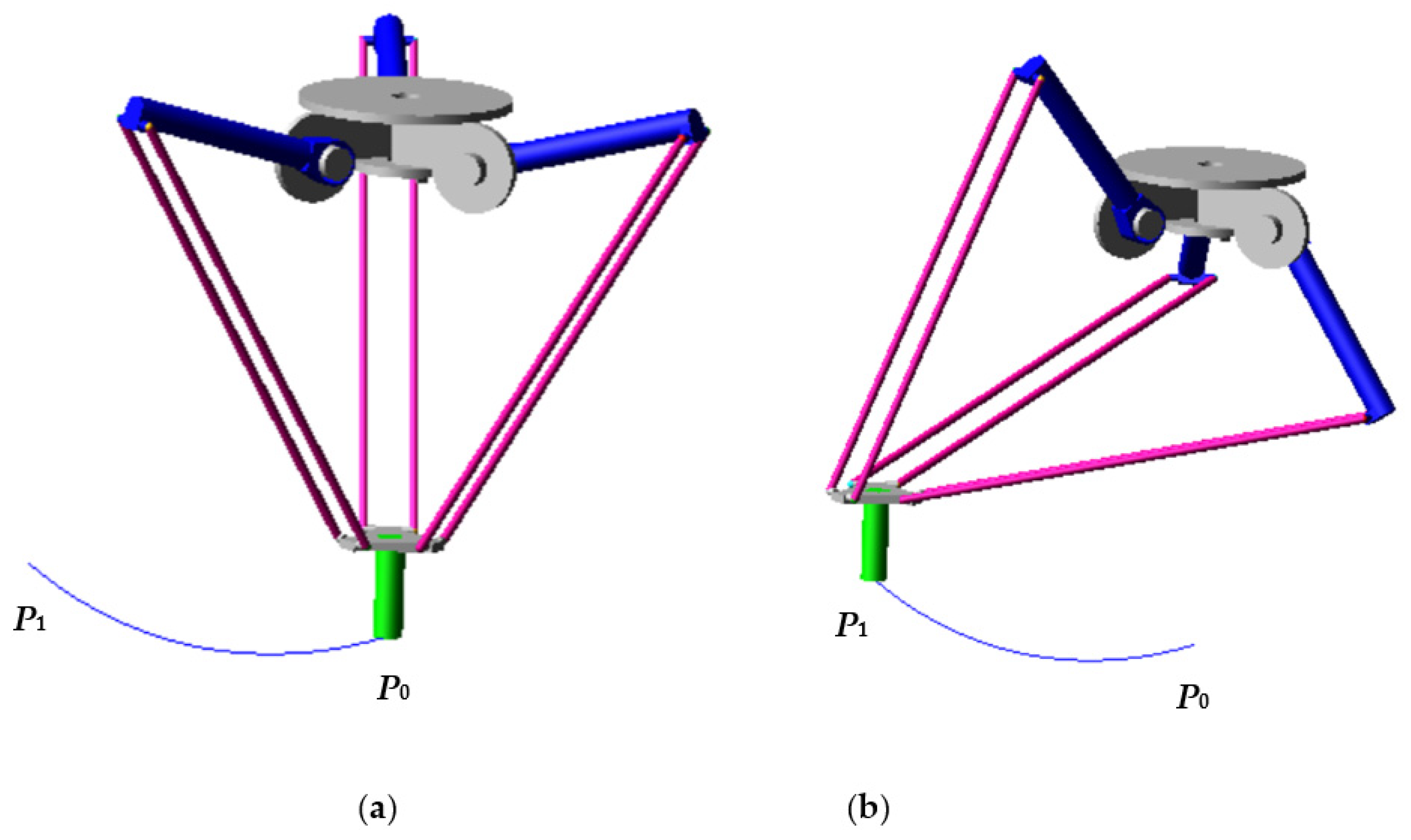
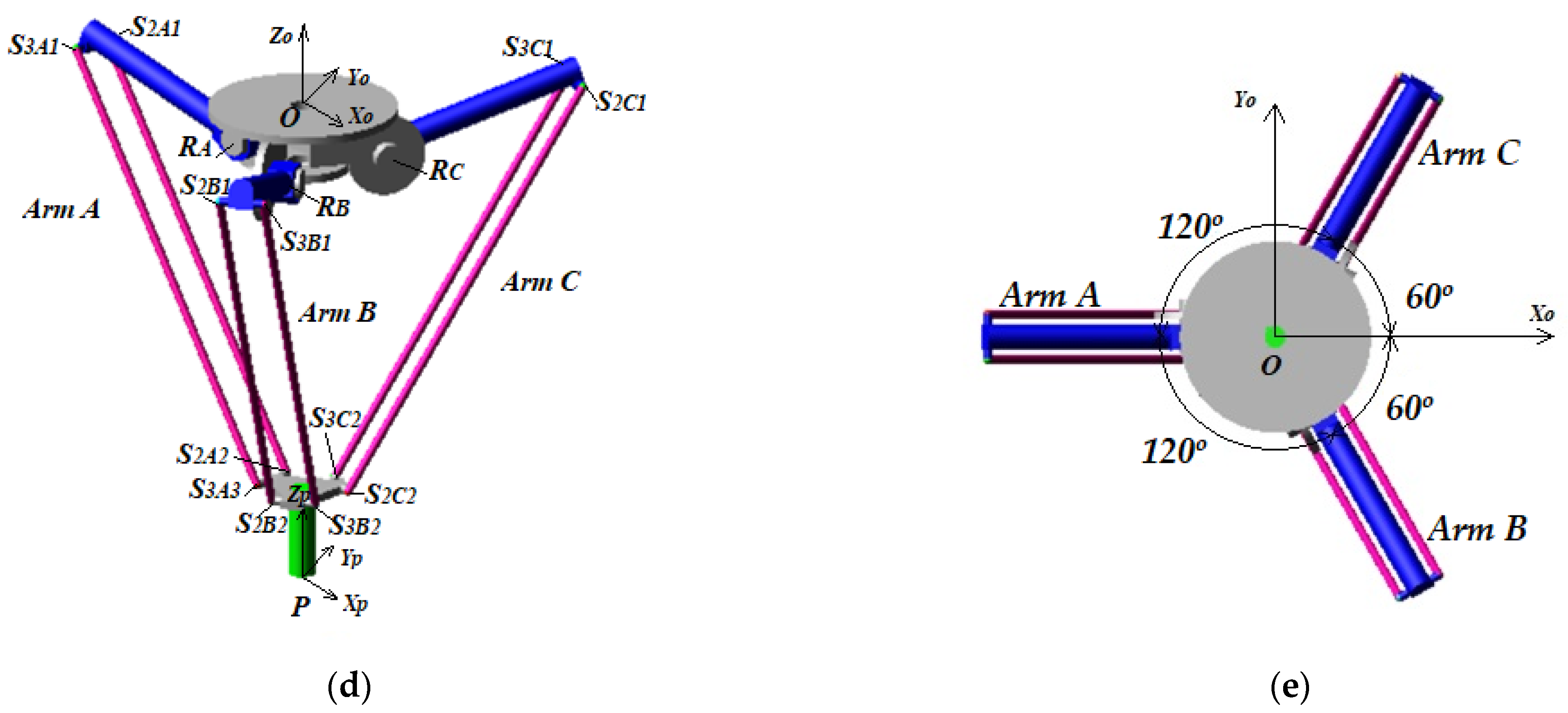
2. Problem Formulation
- -
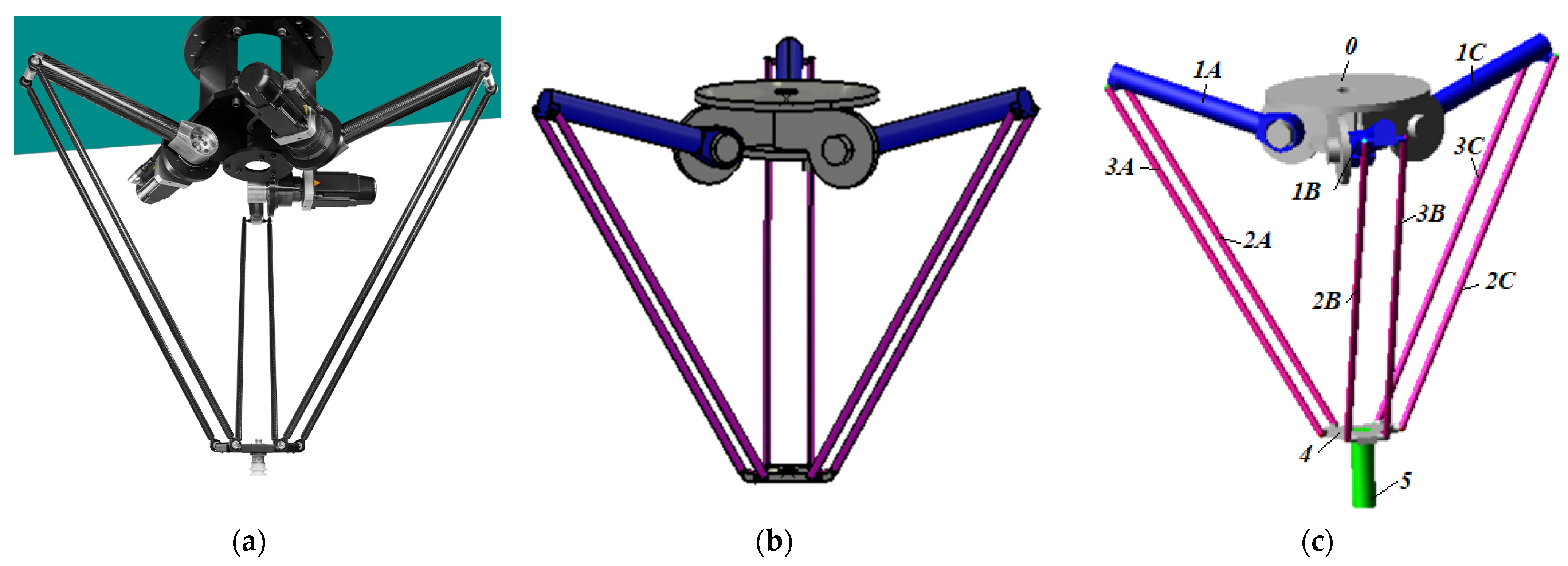
- Elements 0, 1, 4 and 5 are rigid solid bodies;
- -
- Rod Elements 2 and 3 have higher elastic characteristics than the other elements due their dimensions, see Table 2;
- -
- All bodies are made of steel.

| Body | CAD Model | Parameters |
|---|---|---|
| Fixed platform (0) |  | l0 = 125 mm |
| Crank (1) | 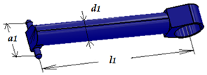 | l1 = 500 mm m1 = 1.58 kg d1 = 62 mm a1 = 106 mm |
| Rod element (2 and 3) | 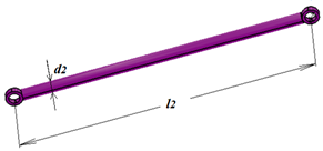 | l2 = l3 = 1106 mm m2 = m3 = 0.34 kg d2 = d3 = 20 mm |
| Mobile platform (4) |  | m4 = 0.46 kg d4 = 20 mm a4 = 106 mm r4 = 97 mm |
| Payload (5) |  | l5 = 212 mm m5 = 5 kg d5 = 50 mm |
- Friction on spherical joints;
- Clearances on spherical joints;
- Elasticity of the flexible rod elements (2 and 3).
- Scenario 1: considers only the frictions from the passive spherical joints (S2k1, S2k2 and S3k1, S3k2, k = A, B, C) assuming steel/steel friction with lubricant.
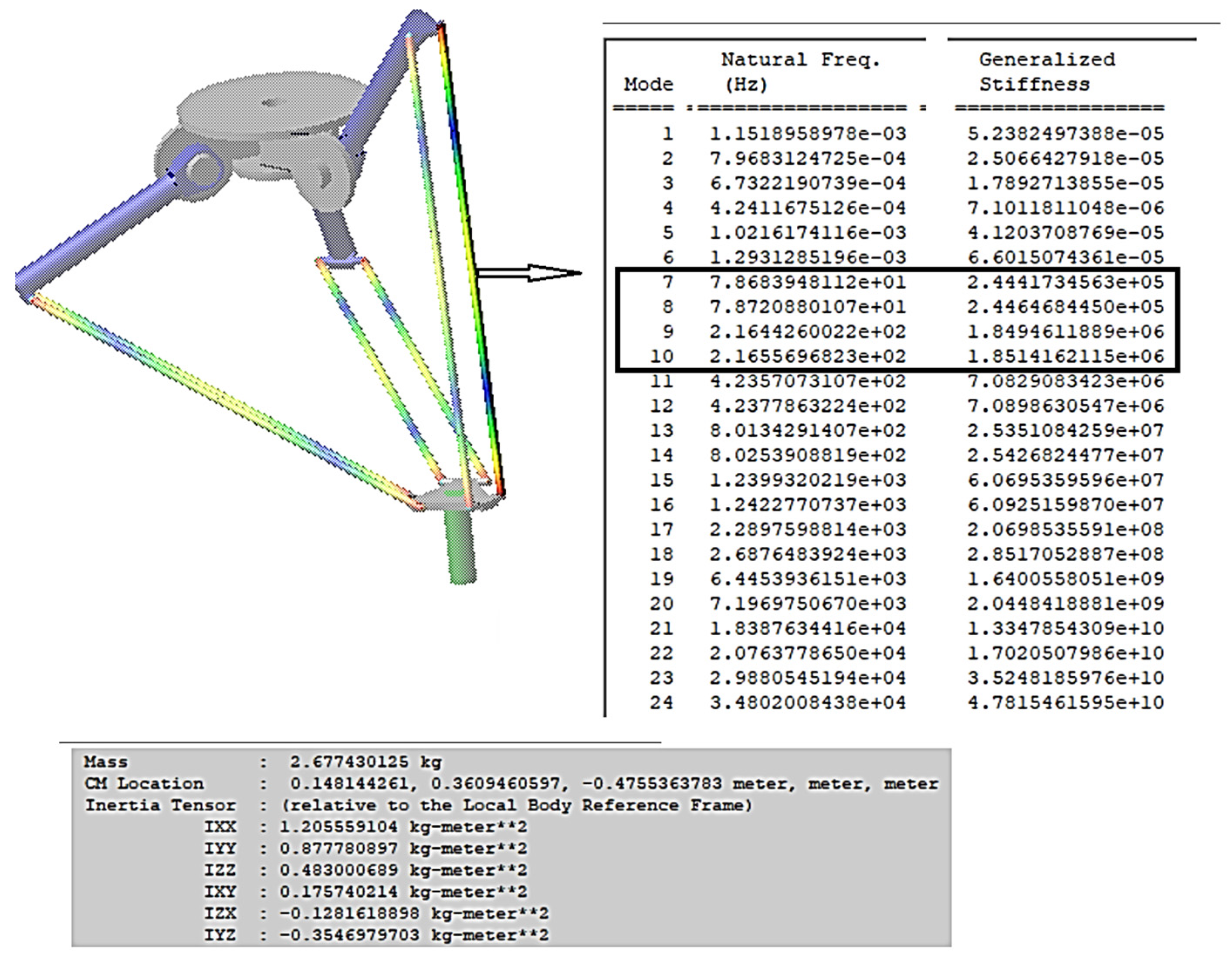
- Scenario 2: considers only the elasticity of Elements 2 and 3 and only allows natural frequencies lower than 250 Hz.
- Scenario 3: considers only the play in the passive spherical joints with the value of 0.1 mm.
- Scenario 4: combines Scenario 1 and Scenario 2.
- Scenario 5: combines Scenario 1 and Scenario 3.
- Scenario 6: combines Scenario 2 and Scenario 3.
- Scenario 7: combines Scenario 1, Scenario 2 and Scenario 3.
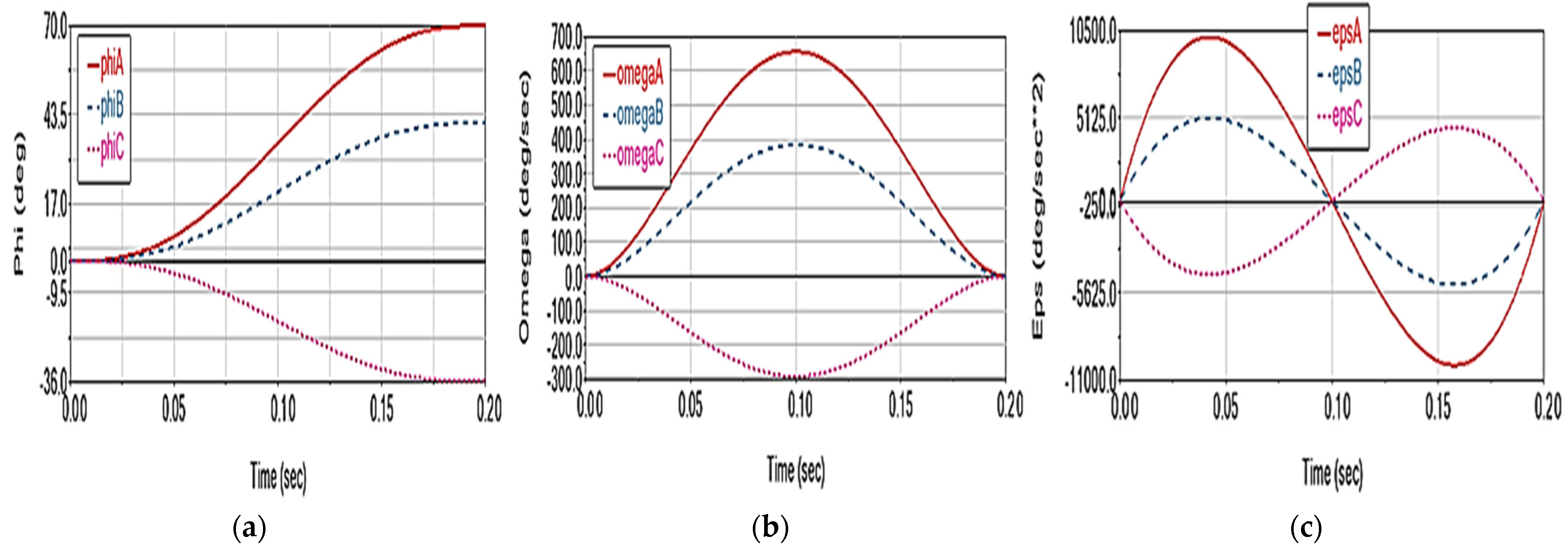
3. Results and Discussions
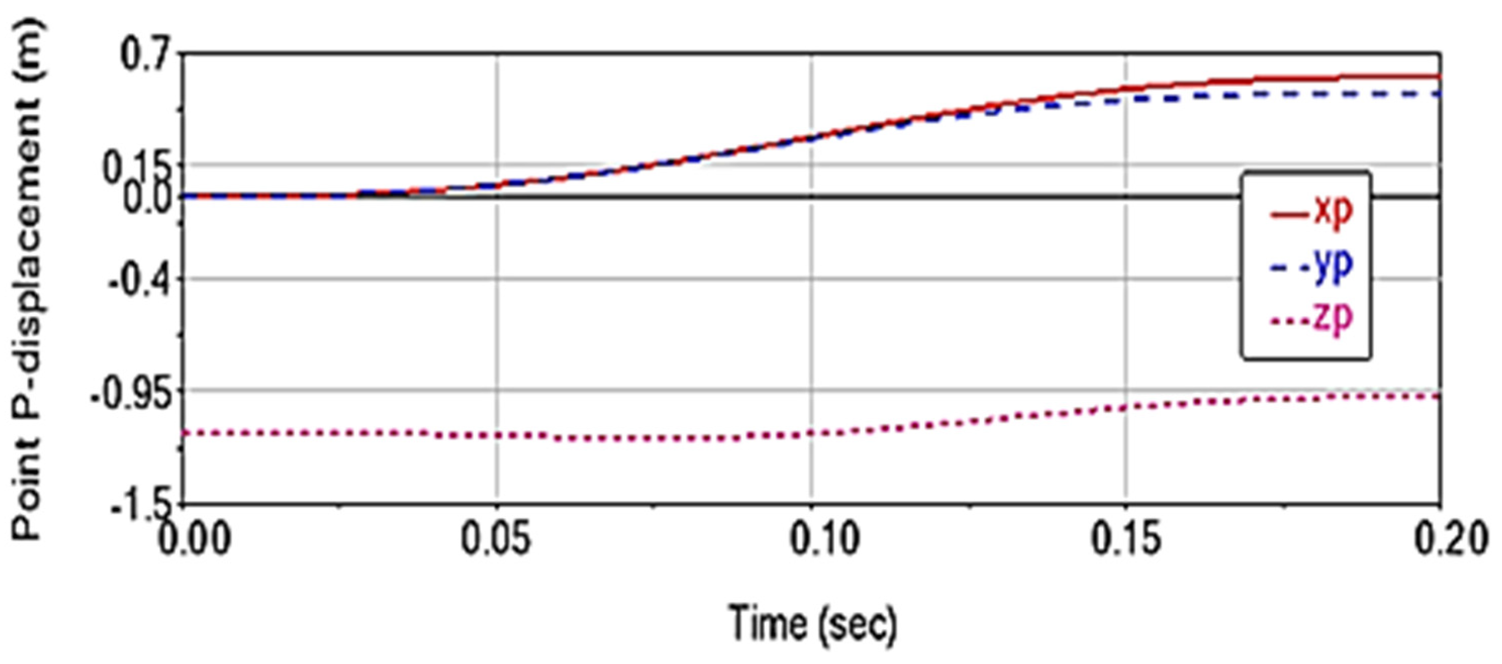
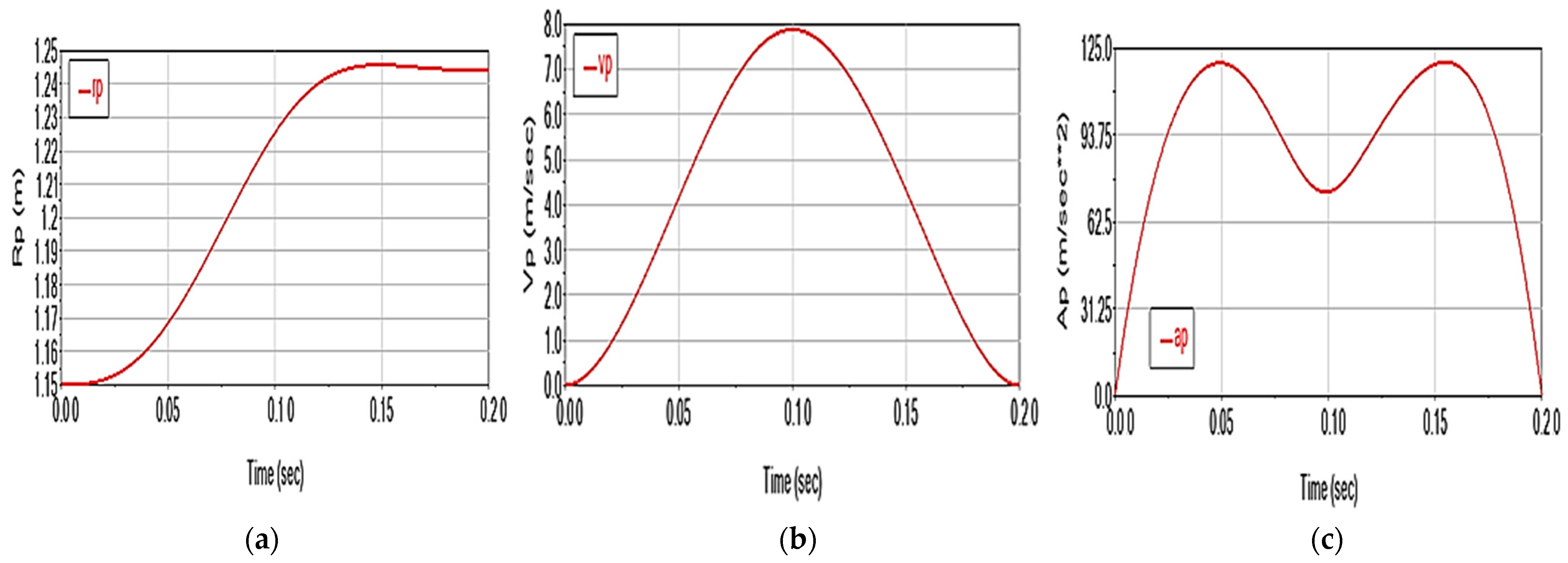
- (a)
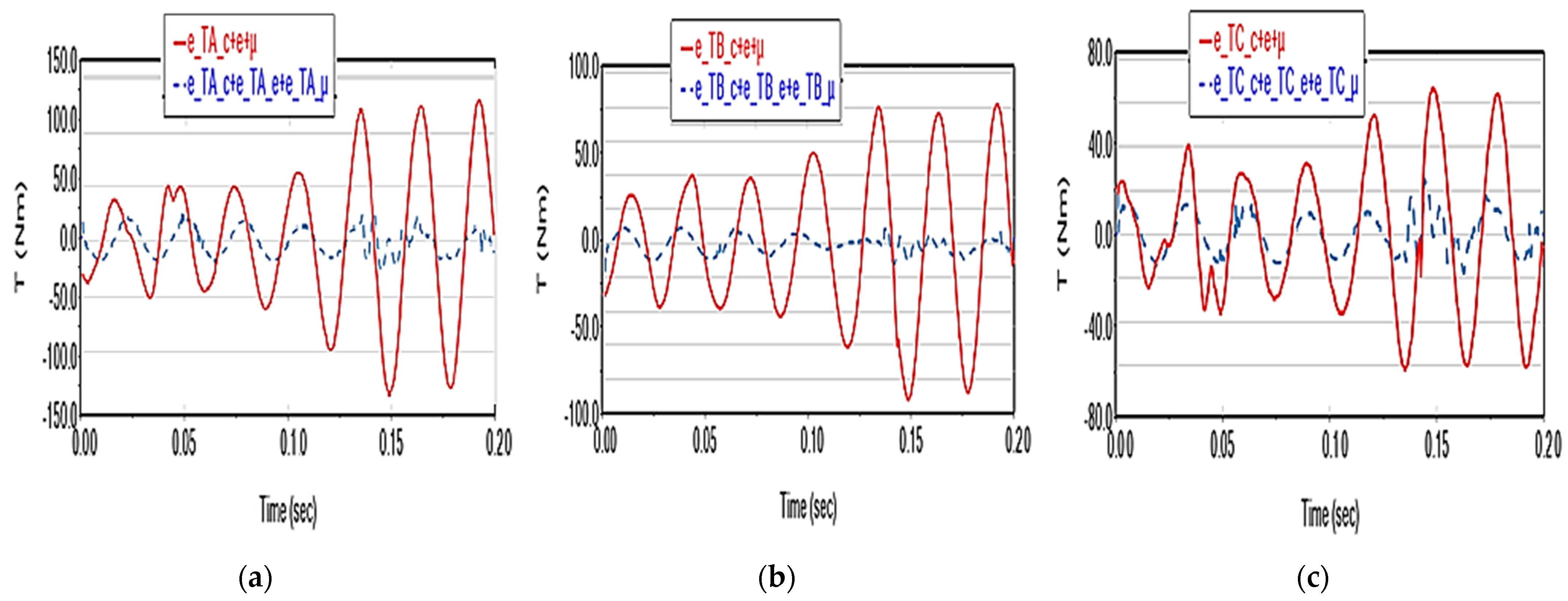
- kinematic (displacements, speeds and accelerations of the characteristic point) and dynamic (driving torques) deviations generated by these factors. These deviations are denoted generically with e_X_p = X_p − X, where X = rP, vP, aP, TA, TB, TC, p is the considered parameter (μ—friction, e—elasticity, c—clearance), and X_p is the value of the X variable in the assumption of considering the p factor, X obtained in the ideal case;
- (b)
- the coupling effect of the factors, i.e., the extent to which they are independent variables and whether their effects can be considered additive phenomena.
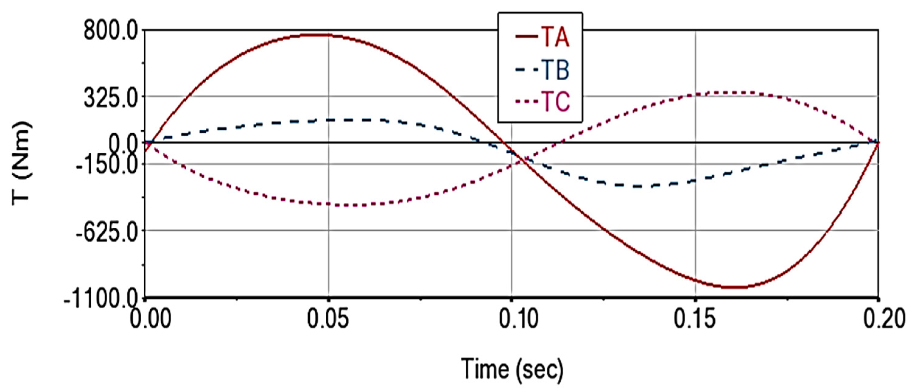
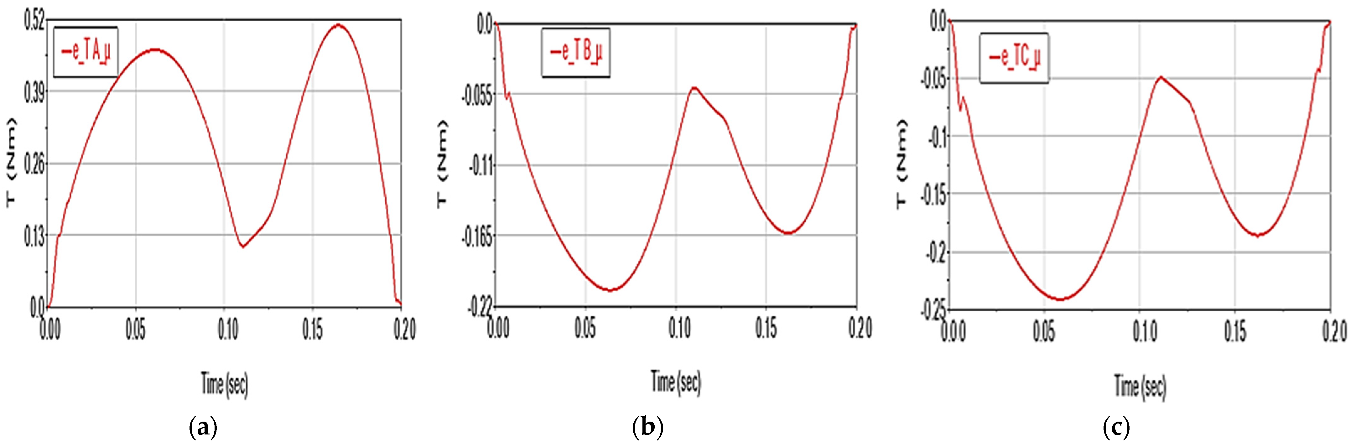
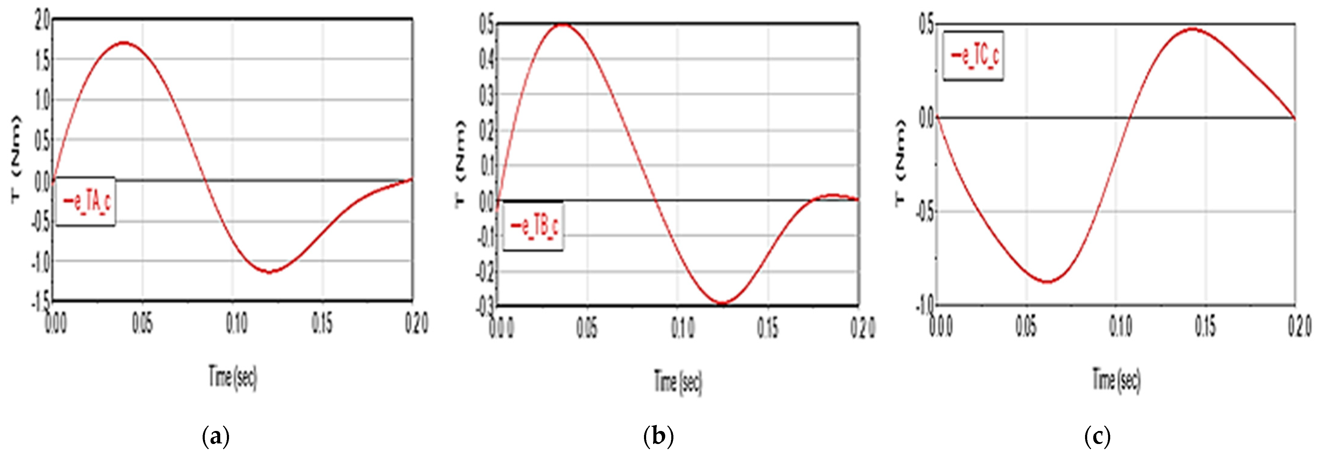
3.1. Scenario 1
- the deviation values e_Tk_μ, k = A, B, C are directly proportional to the absolute values of the moments Tk;
- friction leads to an increase in the driving torques value during the acceleration phase (0.0–0.1 s interval) and helps the motors to brake during the deceleration phase (0.1–0.2 s).
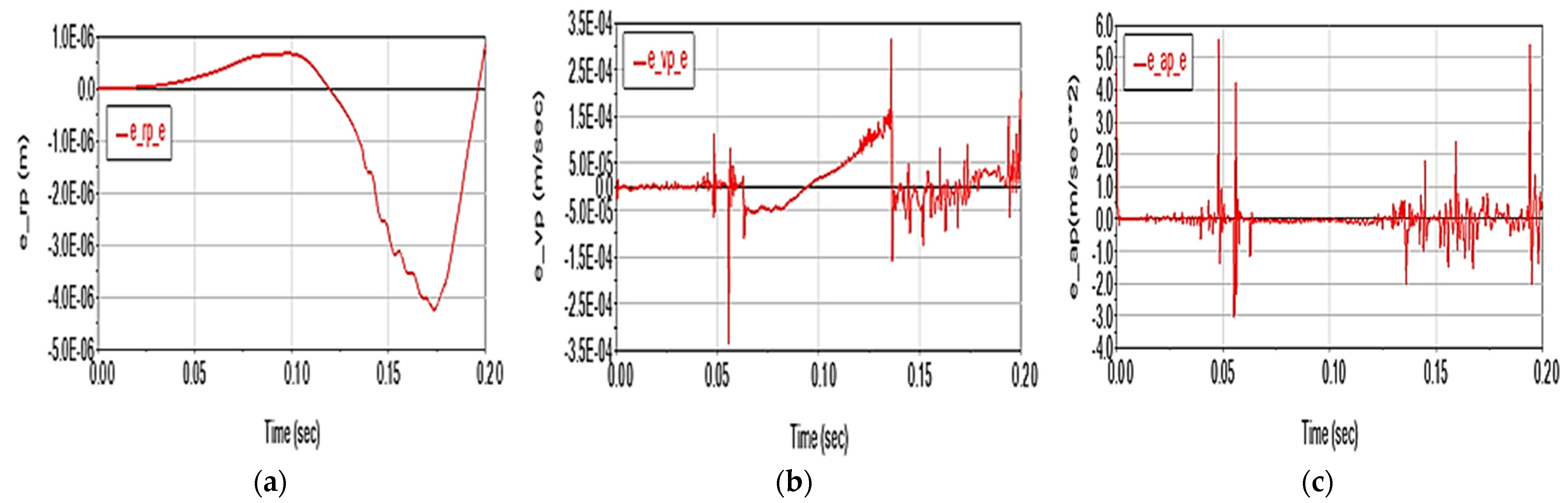
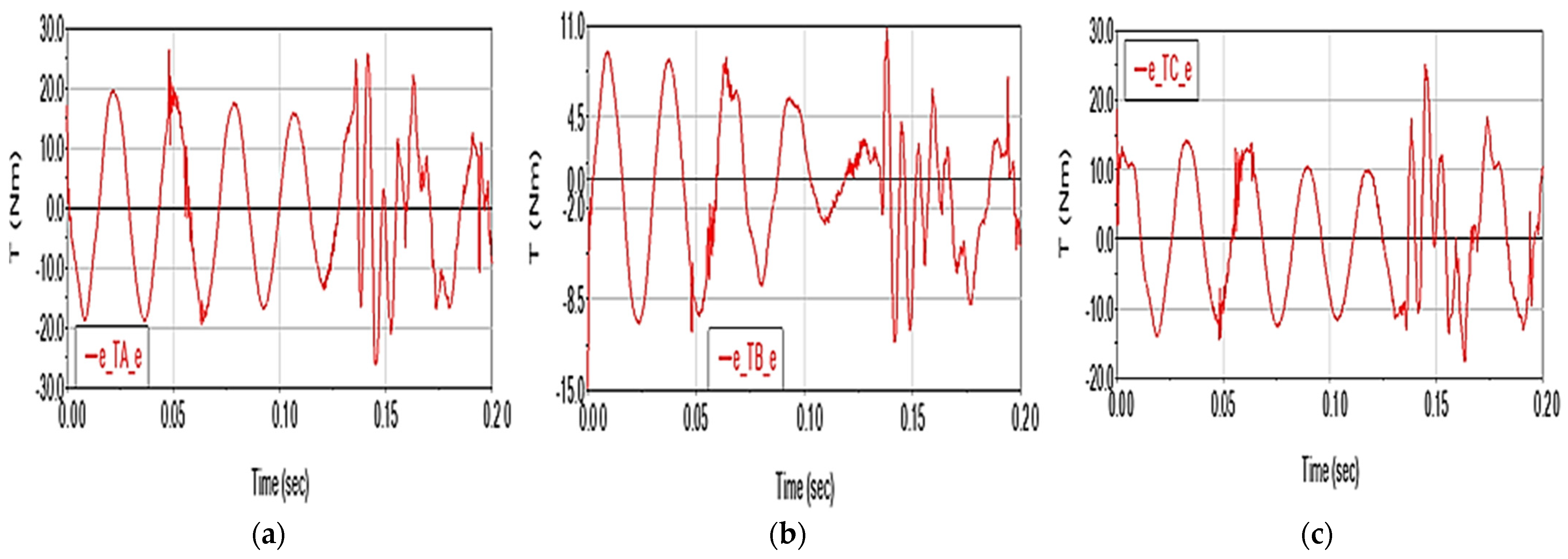
3.2. Scenario 2
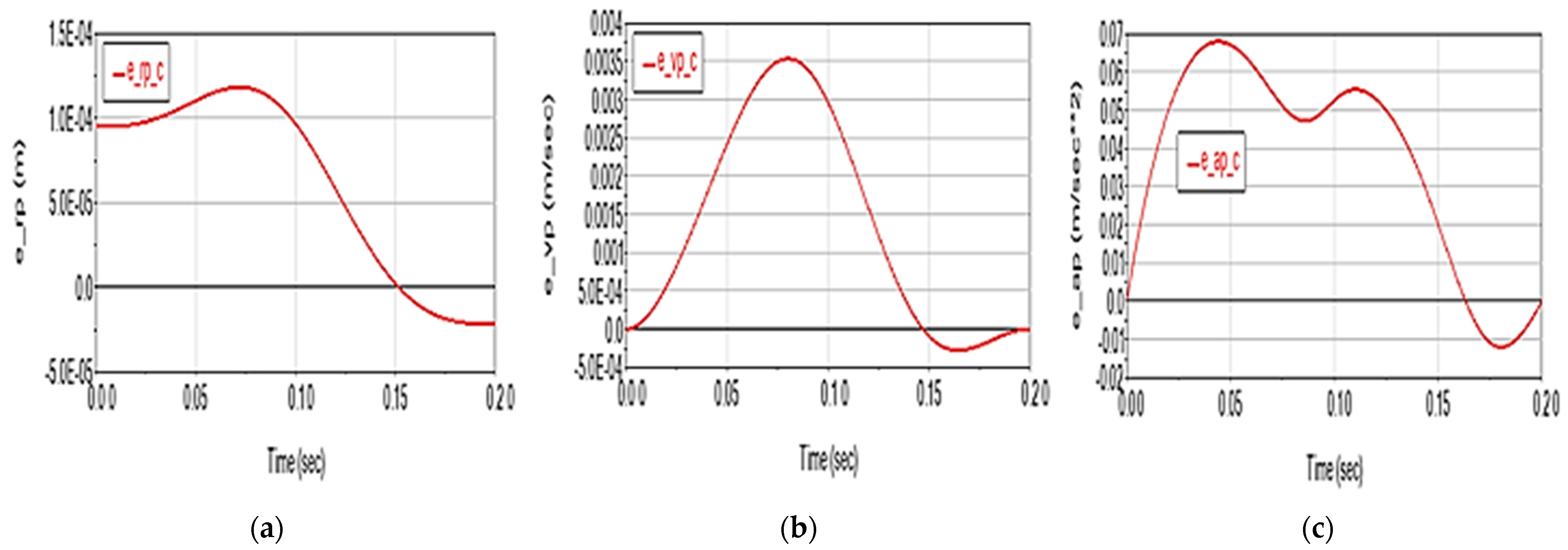
3.3. Scenario 3
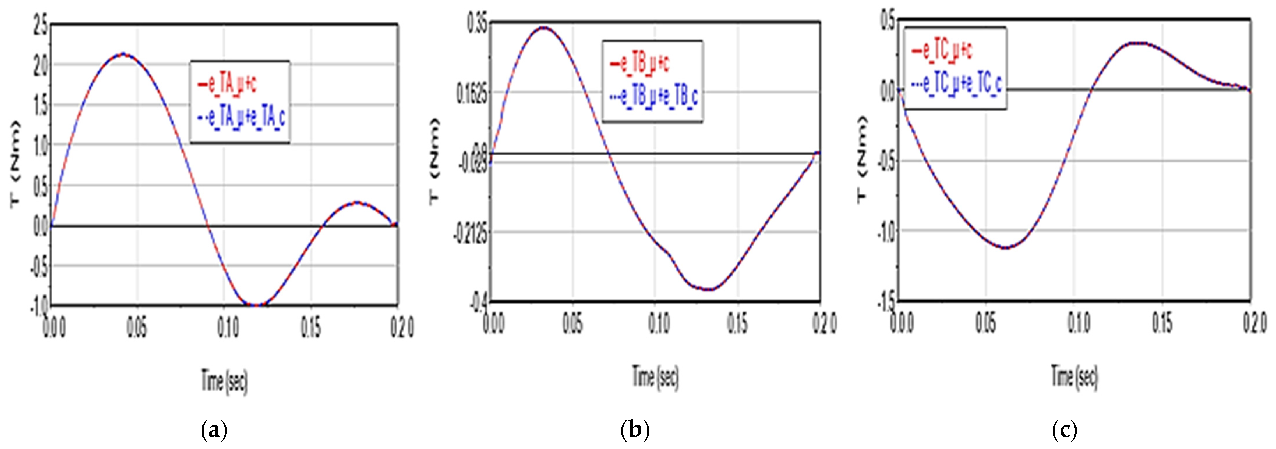
3.4. Scenario 4
3.5. Scenario 5
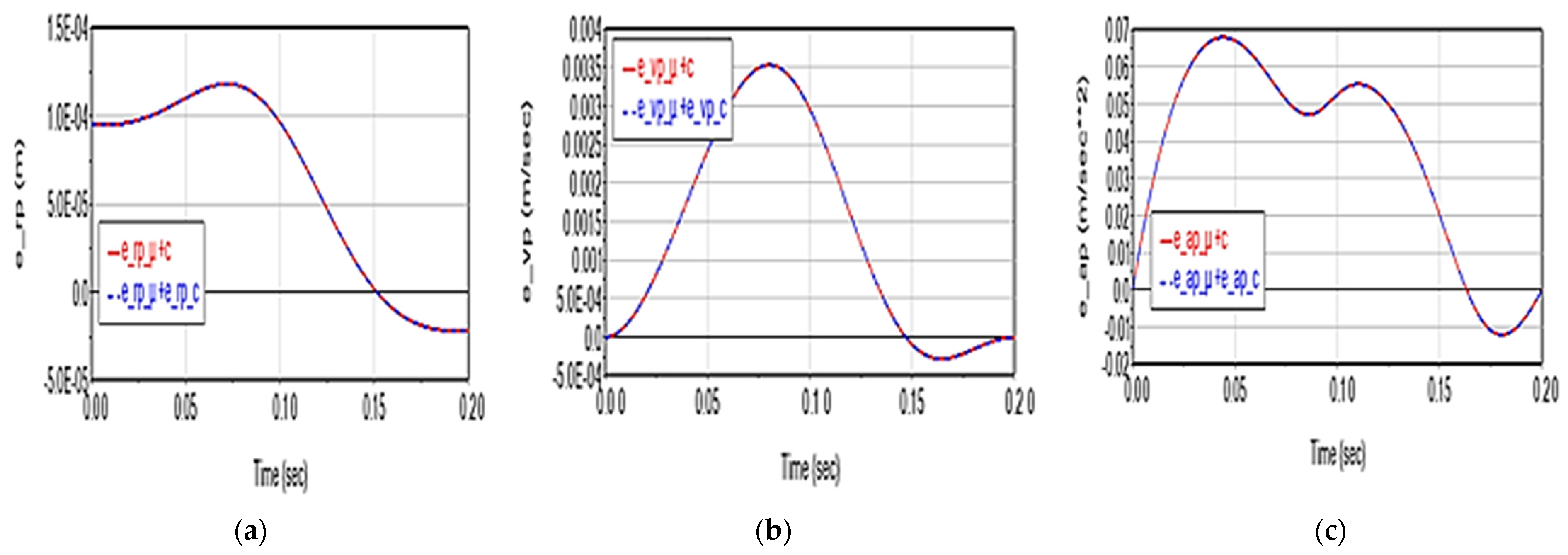
3.6. Scenario 6
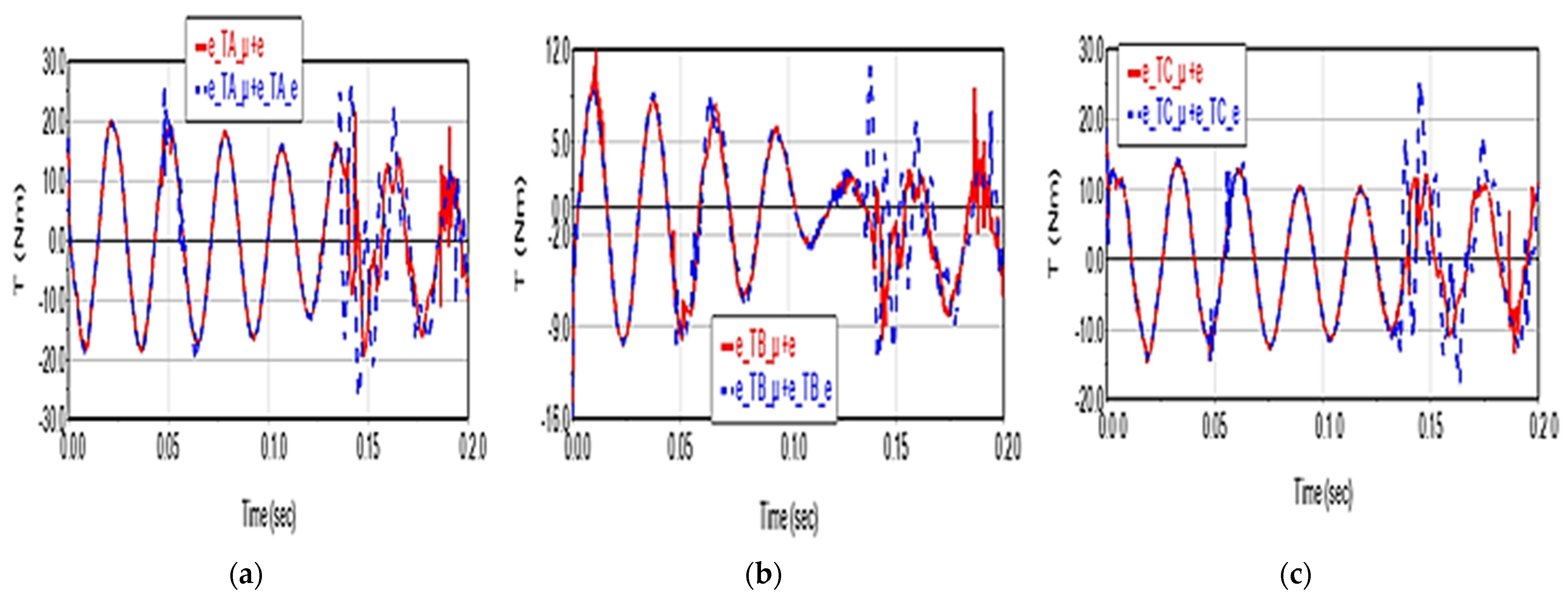
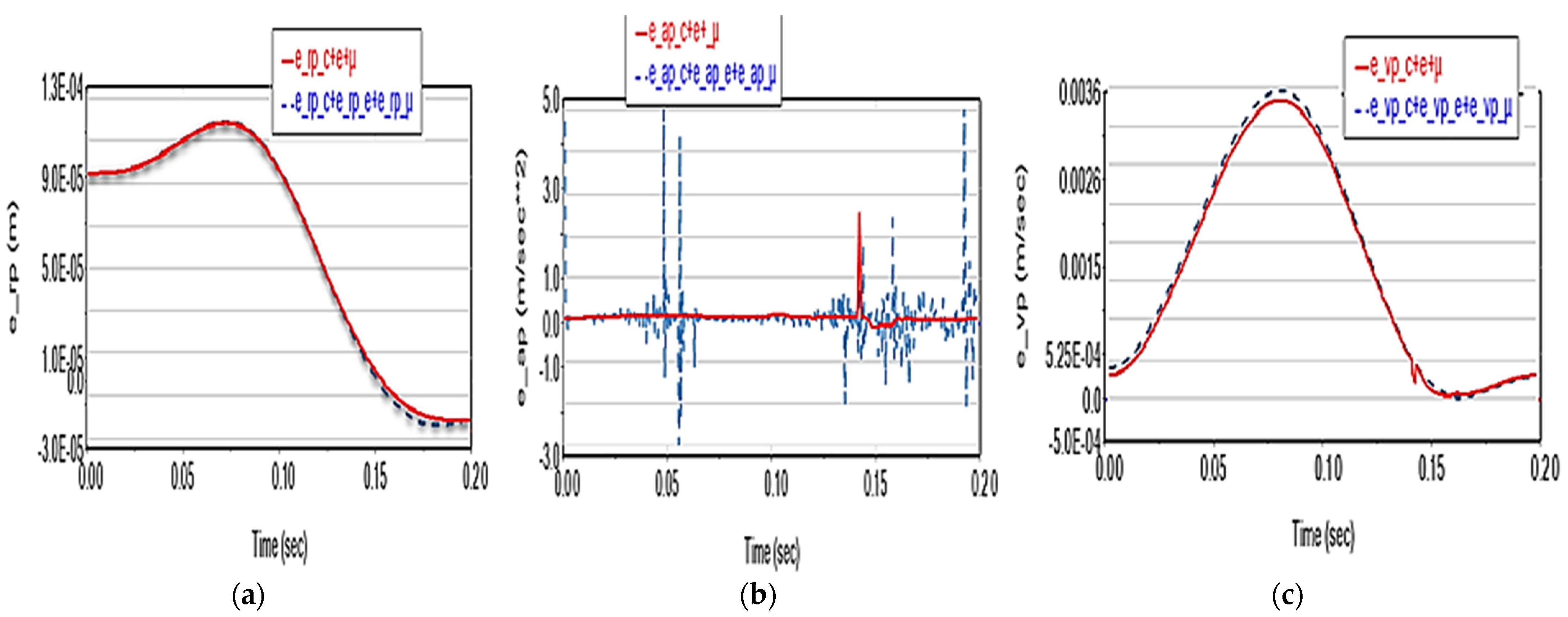
3.7. Scenario 7
4. Conclusions
- -
- Friction has an insignificant influence on the movement parameters of the characteristic point (displacement, speed, acceleration);
- -
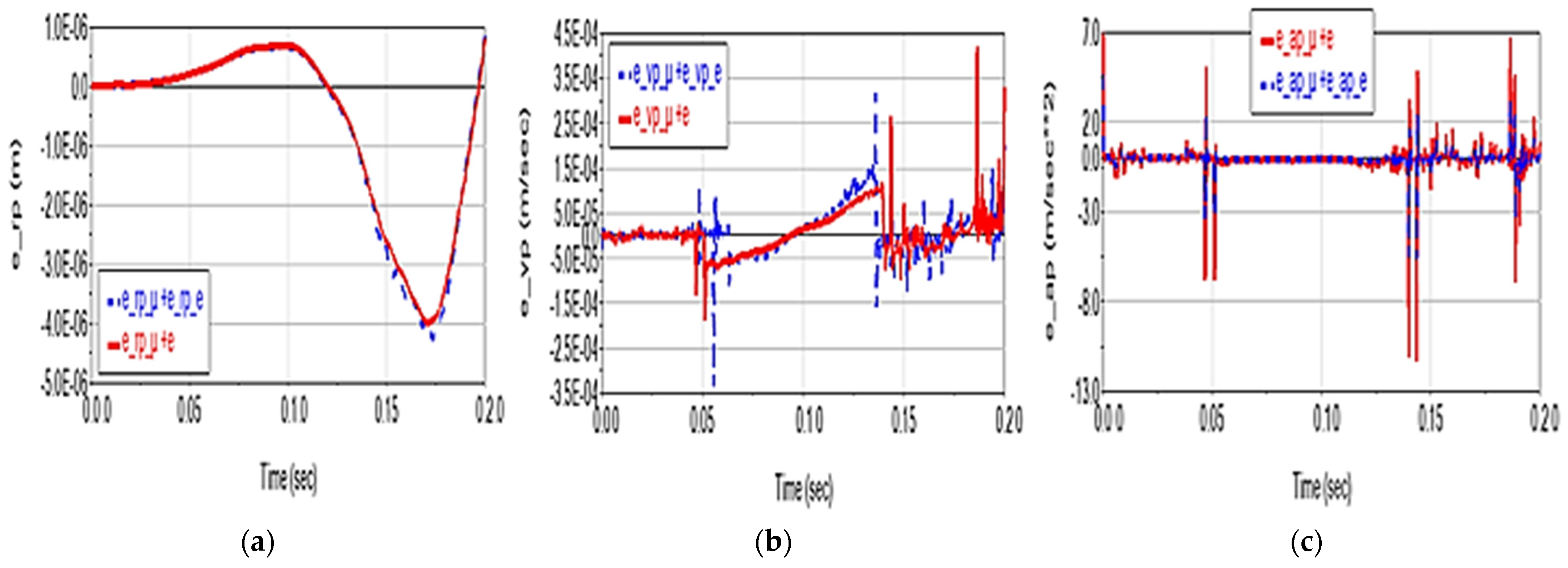
- The elasticity of the elements causes practically negligible deviations in the displacement on the trajectory (of the order of 10−6 m), small deviations on velocity (of the order of 10−4 m/s), but significant in the acceleration (of up to 5 m/s2);
- -
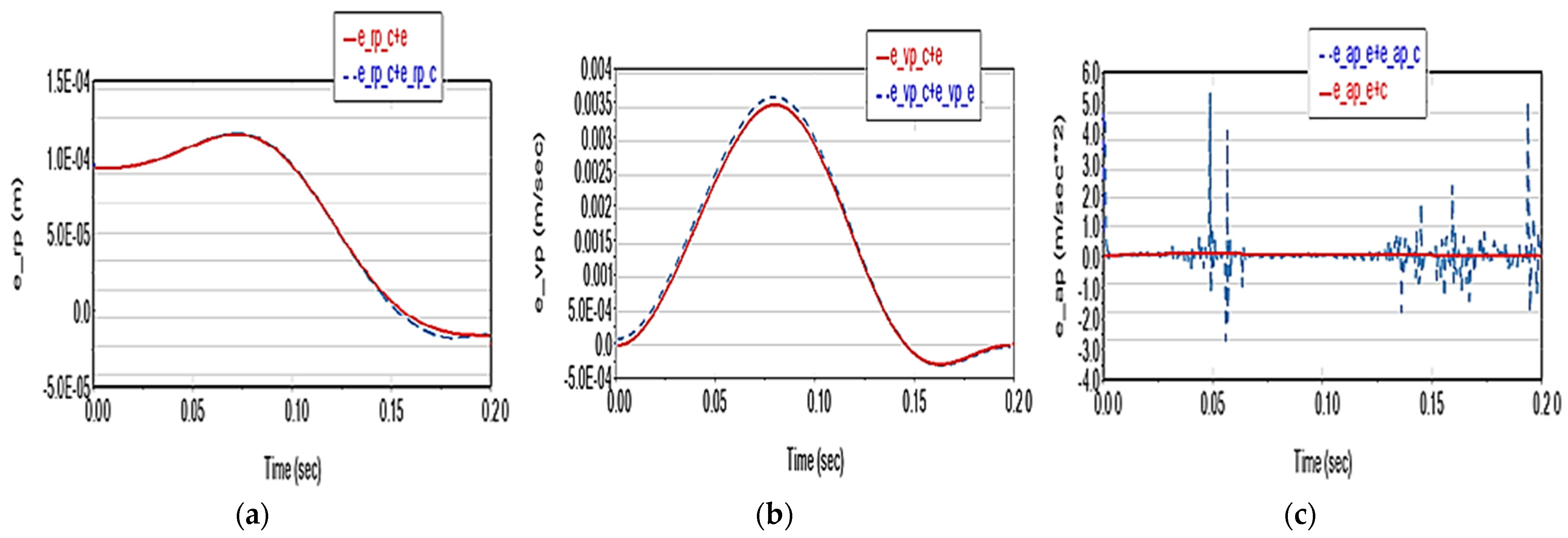
- Joint clearances (considered at the value of 0.1 mm) have a substantial effect on the characteristic point displacement (deviations of the order of 10−4 m), moderate on velocity (of the order of 10−3 m/s) and relatively negligible on acceleration (of order 10−2 m/s2);
- -
- The coupling of any two of these factors results in the cumulative effects on kinematics and dynamics, except in Scenario 6, where the deviations reach values three times higher than those in the case of the individual effects summation;
- -
- The coupling of the three factors leads, from a kinematic point of view, to a slight reduction in deviations, except for acceleration, where a significant reduction in deviations, and especially in picks, can be observed, leading to a better numerical integration solution;
- -
- Regarding dynamics, the effects of the three factors are the following:
- -
- Friction in the joints causes a practically insignificant variation in the driving torques (of the order of 10−1 N·m) compared to their nominal values of the order of 103 N·m (<750 N·m);
- -
- The elasticity of the elements has a substantial impact on driving torques (deviations of up to 25 N·m, i.e., 3.3%, with a harmonic evolution);
- -
- Joint clearances have a moderate effect on driving torques (<2 N·m);
- -
- When two factors are combined (except in Scenario 6), the deviations can reach vaues up to two times higher compared to the case of the summation of individual effects and values up to three times higher when all three factors are combined.
Author Contributions
Funding
Institutional Review Board Statement
Informed Consent Statement
Data Availability Statement
Conflicts of Interest
References
- Clavel, R. Dispositif Pour le Déplacement et le Positionnement d’un Elément dans L’espace. Google Patents WO1987003528A1, 18 June 1987. [Google Scholar]
- Angel, L.; Bermudez, J.; Munoz, O. Dynamic optimization and building of a parallel delta-type robot. In Proceedings of the International Conference on Robotics and Biomimetics, Shenzhen, China, 12–14 December 2013; pp. 444–449. [Google Scholar] [CrossRef]
- Zhang, J.; Shi, L.; Gao, R.; Lian, C. A Method for obtaining direct and inverse pose solutions to Delta parallel robot based on ADAMS. In Proceedings of the International Conference on Mechatronics and Automation, Changchun, China, 9–12 August 2009; pp. 1332–1336. [Google Scholar] [CrossRef]
- Guglielmetti, P.; Longchamp, R. A closed form inverse dynamics model of the delta parallel robot. IFAC Proc. Vol. 1994, 27, 51–56. [Google Scholar] [CrossRef]
- Dastjerdi, A.H.; Sheikhi, M.M.; Masouleh, M.T. A complete analytical solution for the dimensional synthesis of 3-DOF delta parallel robot for a prescribed workspace. Mech. Mach. Theory 2020, 153, 103991. [Google Scholar] [CrossRef]
- Zhang, L.; Mei, J.; Zhao, X.; Huang, T. Dimensional synthesis of the Delta robot using transmission angle. Robotica 2011, 30, 343–349. [Google Scholar] [CrossRef]
- Huiping, S.; Qingmei, M.; Ju, L.; Jiaming, D.; Guanglei, W. Kinematic sensitivity, parameter identification and calibration of a non-fully symmetric parallel Delta robot. Mech. Mach. Theory 2021, 161, 104311. [Google Scholar]
- Miller, K. Experimental Verification of Modeling of Delta Robot Dynamics by Direct Application of Hamilton’s Principle. In Proceedings of the IEEE International Conference on Robotics and Automation (ICRA), Nagoya, Japan, 21–27 May 1995; pp. 532–537. [Google Scholar]
- Falezza, F.; Vesentini, F.; Di Flumeri, A.; Leopardi, L.; Fiori, G.; Mistrorigo, G.; Muradore, R. A novel inverse dynamic model for 3-DoF delta robots. Mechatronics 2022, 83, 102752. [Google Scholar] [CrossRef]
- Brinker, J.; Corves, B.; Wahle, M. A comparative study of inverse dynamics based on clavel’s delta robot. In Proceedings of the 14th World Congress in Mechanism and Machine Science, Taipei, China, 25–30 October 2015; pp. 25–30. [Google Scholar]
- Codourey, A. Dynamic modelling and mass matrix evaluation of the delta parallel robot for axes decoupling control. In Proceedings of the IEEE/RSJ International Conference on Intelligent Robot and Systems, Osaka, Japan, 4–8 November 1996; Volume 3, pp. 1211–1218. [Google Scholar]
- Asadi, F.; Heydai, A. Analitical dynamic modeling of Delta robot with experimental verification. Proc. Inst. Mech. Eng. Part K J. Multi-Body Dyn. 2020, 234, 623–663. [Google Scholar]
- Rat, N.R.; Neagoe, M.; Gogu, G.; Stan, S.D. Dynamic analysis of an Isoglide3-T3 parallel robot. In Proceedings of the Annals of DAAAM 2009 & Proceedings of the 20th International DAAAM Symposium “Intelligent Manufacturing & Automation: Theory, Practice & Education”, Vienna, Austria, 25–28 November 2009; p. 15. [Google Scholar]
- Cretescu, N.; Neagoe, M. Dynamic Modelling of an Isoglide T3 Type Parallel Robot. In New Advances in Mechanisms, Mechanical Transmissions and Robotics MTM&Robotics; Springer International Publishing: Cham, Switzerland, 2020; pp. 235–248. [Google Scholar] [CrossRef]
- Raţ, N.R.; Neagoe, M.; Stan, S.D. Comparative Dynamic Analysis of Two Parallel Robots. In Solid State Phenomena; Trans Tech Publications Ltd.: Stafa-Zurich, Switzerland, 2010; pp. 345–356. [Google Scholar]
- Rat, N.; Neagoe, M.; Gogu, G. Theoretical and Experimental Research on the Dynamics of a 4DOF Isoglide 4-T3R1 Parallel Robot. In Proceedings of the SYROM 2009: 10th IFToMM International Symposium on Science of Mechanisms and Machines, Brasov, Romania, 12–15 October 2009; pp. 387–396. [Google Scholar] [CrossRef]
- Rat, N.R.; Neagoe, M.; Diaconescu, D.; Stan, S.D. Dynamic analysis of a Triglide parallel robot. In Proceedings of the 4th International Conference on Human System Interaction (HSI), Yokohama, Japan, 19–21 May 2011; pp. 245–249. [Google Scholar]
- Robert, L.; Williams, I.I. The Delta Parallel Robot: Kinematics Solutions, Mechanical Engineering. Ph.D. Thesis, Ohio University, Athens, Ohio, 2016. [Google Scholar]
- Hamdoun, O.; Bakkali, L.E.; Baghli, F.Z. Analysis and Optimum Kinematic Design of a Parallel Robot. In Proceedings of the 10th International Conference Interdisciplinarity in Engineering, Tirgu Mures, Romania, 6–7 October 2016. [Google Scholar]
- Hugo, H.; Joan, L. The Forward and Inverse Kinematics of a Delta Robot, Chapter. In Proceedings of the Advances in Computer Graphics: 37th Computer Graphics International Conference, CGI 2020, Geneva, Switzerland, 20–23 October 2020. [Google Scholar] [CrossRef]
- Gosselin, C.; Angeles, J. The Optimum Kinematic Design of a Planar Three-Degree-of-Freedom Parallel Manipulator. J. Mech. Transm. Autom. 1988, 110, 35–41. [Google Scholar] [CrossRef]
- Cheng, L.; Guohua, C.; Yongyin, Q. Safety Analysis via Forward Kinematics of Delta Parallel Robot using Machine Learning. Saf. Sci. 2019, 117, 243–249. [Google Scholar]
- Swaraj, Z.; Sharad, K.P. Matlab Toolbox for Kinematic Analysis and Simulation of Dexterous Robotic Grippers. In Proceedings of the 12th Global Congress on Manufacturing and Management, GCMM 2014, Procedia Engineering, Vellore, India, 8–10 December 2014; Volume 97, pp. 1886–1895. [Google Scholar]
- Carmelo, M.; Stephen, G.P.; Pascual, I.N.; Ian, C. Robotic path Planning for Non-Destructive Testing—A Custom MATLAB Toolbox, Approach. Robot. Comput.-Integr. Manuf. 2016, 37, 1–12. [Google Scholar]
- Ma, L.; Dexue, B.; Zhipeng, X. Mechanism Simulation and Experiment of 3-DOF Parallel Robot Based on MATLAB. In Proceedings of the 2015 International Power, Electronics and Materials Engineering Conference, Dalian, China, 16–17 May 2015. [Google Scholar]
- Shehata, M.; Elshami, M.; Bai, Q.; Zhao, X. Parameter Estimation for Multibody System Dynamic Model of Delta Robot from Experimental Data. IFAC-PapersOnLine 2021, 54, 72–77. [Google Scholar] [CrossRef]
- Cretescu, N.; Neagoe, M.; Saulescu, R. Kinematic and Dynamic Analysis of a 4DOF Parallel Robot with Flexible Links. In Proceedings of the Joint International Conference of the XII International Conference on Mechanisms and Mechanical Transmissions (MTM) and the XXIII International Conference on Robotics (Robotics ’16), Aachen, Germany, 26–27 October 2016; pp. 473–481. [Google Scholar]
- Cretescu, N.R.; Neagoe, M. Rigid versus Flexible Link Dynamic Analysis of a 3DOF Delta Type Parallel Manipulator. Appl. Mech. Mater. 2015, 762, 101–106. [Google Scholar] [CrossRef]
- Rat, N.R.; Neagoe, M. Rigid vs. flexible links dynamic analysis of a 3DOF parallel robot. In Proceedings of the 3rd IEEE International Conference on ASME 2009, DEST ’09, San Diego, CA, USA, 30 August–2 September 2009; pp. 534–539. [Google Scholar]
- Kuo, Y.-L. Mathematical modeling and analysis of the Delta robot with flexible links. Comput. Math. Appl. 2016, 71, 1973–1989. [Google Scholar] [CrossRef]
- Wu, M.; Mei, J.; Zhao, Y.; Niu, W. Vibration reduction of delta robot based on trajectory planning. Mech. Mach. Theory 2020, 153, 104004. [Google Scholar] [CrossRef]
- Kermanian, A.; Kamali, E.A.; Taghvaeipour, A. Dynamic analysis of flexible parallel robots via enhanced co-rotational and rigid finite element formulations. Mech. Mach. Theory 2019, 139, 144–173. [Google Scholar] [CrossRef]
- Weiss, C.; Morlock, M.M.; Hoffmann, N.P. Friction induced dynamics of ball joints: Instability and post bifurcation behavior. Eur. J. Mech.-A/Solids 2014, 45, 161–173. [Google Scholar] [CrossRef]
- Li, Y.; Shang, D.; Fan, X.; Liu, Y. Motion Reliability Analysis of the Delta Parallel Robot considering Mechanism Errors. Math. Probl. Eng. 2019, 2019, 3501921. [Google Scholar] [CrossRef]
- SIPRO. Available online: https://www.sipro.vr.it/en/delta-robot/delta-robot-SIAX-D3-1600.html (accessed on 4 November 2022).
- Engineeringlibrary. Available online: https://engineeringlibrary.org/reference/coefficient-of-friction (accessed on 4 November 2022).


| Parameter | Value |
|---|---|
| Total mass | 80 kg |
| Maximum payload | 5 kg |
| Maximum end-effector speed | 8 m/s |
| Maximum end-effector acceleration | 120 m/s2 |
Disclaimer/Publisher’s Note: The statements, opinions and data contained in all publications are solely those of the individual author(s) and contributor(s) and not of MDPI and/or the editor(s). MDPI and/or the editor(s) disclaim responsibility for any injury to people or property resulting from any ideas, methods, instructions or products referred to in the content. |
© 2023 by the authors. Licensee MDPI, Basel, Switzerland. This article is an open access article distributed under the terms and conditions of the Creative Commons Attribution (CC BY) license (https://creativecommons.org/licenses/by/4.0/).
Share and Cite
Cretescu, N.; Neagoe, M.; Saulescu, R. Dynamic Analysis of a Delta Parallel Robot with Flexible Links and Joint Clearances. Appl. Sci. 2023, 13, 6693. https://doi.org/10.3390/app13116693
Cretescu N, Neagoe M, Saulescu R. Dynamic Analysis of a Delta Parallel Robot with Flexible Links and Joint Clearances. Applied Sciences. 2023; 13(11):6693. https://doi.org/10.3390/app13116693
Chicago/Turabian StyleCretescu, Nadia, Mircea Neagoe, and Radu Saulescu. 2023. "Dynamic Analysis of a Delta Parallel Robot with Flexible Links and Joint Clearances" Applied Sciences 13, no. 11: 6693. https://doi.org/10.3390/app13116693
APA StyleCretescu, N., Neagoe, M., & Saulescu, R. (2023). Dynamic Analysis of a Delta Parallel Robot with Flexible Links and Joint Clearances. Applied Sciences, 13(11), 6693. https://doi.org/10.3390/app13116693