Featured Application
Concrete Pavement Solar Collector Technology.
Abstract
The urban heat island (UHI) effect occurs when cities and towns warm up more than the surrounding rural areas because they have more structures and less vegetation and soil. The issue can be lessened by implementing a pavement solar collector (PSC) system, which converts heat from the pavement’s surface into thermal energy. In this work, the authors analyze the effect of pipe depth (85 mm to 50 mm) and spacing (200 mm to 100 mm) on the efficiency of heat extraction from the surface while taking pavement structural performance into account using the ANSYS Fluent program. The modeling approach was validated against the previous studies. According to the findings, a concrete water harvesting system may achieve the maximum outlet temperature with the least impact on traffic loading by using a distance of 100 mm and a depth of 85 mm. The load’s impact is 51% less than that of the model that predicted the highest outlet temperature, and the outside temperature is reduced by 3.9%. The outcomes here demonstrated that concrete might be employed in the PSC system as an alternative to asphalt.
1. Introduction
Urban heat islands (UHIs) form due to the loss of natural land cover in modern cities, which is replaced by dense concentrations of paved roads, buildings, and other materials that can absorb and retain heat. This effect not only drives up the cost of energy for things such as air conditioning, for example, but also boosts the levels of air pollution and the danger of heat-related illnesses, as well as mortality rates. Paved surfaces are a significant contributor to the formation of urban heat islands (UHIs) because they occupy around 30 to 45 percent of the total area of cities, making paved surfaces one of the largest contributors to UHIs [1]. As UHIs are a contributing factor to global warming, the United Nations has designated it as a key element of UNESCO SDG No. 13, aimed at addressing climate change and its consequences. To limit global warming to 1.5 °C above pre-industrial levels, the global emissions need to be reduced by 45% below 2010 levels by 2030.
Utilizing pavement solar collectors (PSCs) as a source of renewable energy, i.e., solar energy, as an alternative to burning fossil fuels and lowering greenhouse gas emissions is one way to address this issue. The most common method for constructing PSC involves burying a pipe network beneath the surface of a pavement’s uppermost levels. The surface of the pavement is able to absorb solar radiation on days when the sun is out. The energy is subsequently transferred to the fluid flowing through the pipes, which can be utilized for immediate heating or stored for future use [2]. Reducing the amount of thermal stress that might lead to rutting in concrete and asphalt pavement lowers the pavement’s temperature and lengthens its service life [3]. Hence, the implementation of PSC potentially reduces some of the detrimental consequences being brought to the environment. For example, the PCS system can be employed as an alternative approach to conventional winter road maintenance by providing heat to the pavement, making it an effective method for snow removal during the winter season. The conventional method for winter maintenance of roads consumes between 0.6 and 1.7 million tonnes of salt and sand annually [4]. Soil erosion is induced by road salting, which also poisons water supplies and threatens animals [5].
There have been many investigations into how to make PCS technology more effective. For instance, Basheer Sheeba and Krishnan Rohini (2014) devised three models with varying distances between the pipes (200 mm, 150 mm, and 100 mm) with a constant pipe diameter (20 mm) and depth (75 mm) from the pavement surface to determine how the distance affected heat extraction. It was discovered that when the pipe spacing was reduced from 200 mm to 150 mm while keeping the same pipe depth, the surface temperature decreased because of the increased heat absorption from the surface of the water flow in the pipes, and the outlet temperature increased from 320 K to 322 K. In addition, the author reported that serpentine pipes were more effective at collecting heat compared with straight pipes in asphalt pavement [6]. Meanwhile, Songok et al. suggested that a pipe depth of 300 mm is recommended for ice melting in the winter [7]. Additionally, Ghalandari et al.’s (2022) research demonstrated that increasing the pipe length from 50 m to 200 m leads to a 52% reduction in the overall power extraction per meter of the pipe, dropping from 2.45 kW/m to 1.17 kW/m [8]. Besides pipe spacing, length, and depth, studies show that adjusting the albedo and the fluid flow rate can improve the PSC’s efficiency by up to 49% [9]. For this reason, it is crucial to achieve maximum heat harvesting efficiency during the design phase by configuring and determining the best pipe length for the PSCs.
The presence of pipes inside the pavement brings benefits because it reduces the temperature and reduces the thermal pressure on the pavement [10]. However, the structural integrity also must be taken into account when considering PSC, as damage to the pipes will result in the reduction in pipe spacing as well as pipe depth [6]. When heat pipes are integrated into a pavement system, it drastically alters the system’s mechanical, thermal, and coupling response. According to the results by Patil et al. (2013), the bending zone around the heat pipe is the most vulnerable region of the pavement [11]. As a structural member of pavement is loaded, it is susceptible to a wide variety of damages at any point in the loading process [12]. This is due to the fact that when subjected to fatigue loads, the strength and durability of concrete paving deteriorate dynamically. Results also show that the concrete pavement’s bending strength responded differently depending on the stress ratio, initially increasing before falling at a stress ratio of 0.5 and then persistently declining at a stress ratio of 0.8 [13].
According to a review of the literature, little research has been conducted on the effects of traffic load factors and pipe system configuration on concrete pavement performance. Due to the limited studies of solar energy harvesting from concrete pavement being conducted and the rise in the usage of concrete pavements to date, it is necessary to investigate and determine the factors that affect harvesting of the highest energy by focusing on the integral piping variables for concrete pavement (spacing between pipes and depth of pipes from the surface). Recent trends in PCS research employing asphalt and concrete are displayed in Table 1. Table 1 demonstrates that multiple investigations have been carried out on the utilization of asphalt for PVC, whereas only a single research study has been conducted on concrete material. No extensive studies have been conducted on the feasibility of using concrete as a pavement solar collector in paved areas.

Table 1.
List of areas of studies related to concrete and asphalt material for PCS.
Frequent high traffic loads are a primary contributor to pavement failure, with the extent of damage being contingent upon the characteristics of the vehicle and the number of axles present. These issues cause high maintenance costs over the years and if not properly addressed can lead to loss of lives. In comparison with asphalt, concrete pavements have many advantages, including lower life cycle costs, greater resistance to wear, longer lifespan, reduced environmental impact, and easier management of maintenance and repairs [20]. In addition, concrete pavements are commonly utilized in high-load-bearing applications, such as highways, airports, and bridge decks, due to their durability and ability to provide long-lasting solutions [21].
In this study, the load of a vehicle with a single axle will be applied. Since most of the existing studies focused on asphalt pavement and the fatigue that occurs due to the impact of loads, this study evaluates the effect of loads on the concrete pavement when it is used as a solar collector. In addition, we assess the impact of traffic loads on the sustainability of paving and harvesting the highest energy by adopting the variables of depth and distance between energy collection pipes.
The modeling set-up is initially validated with Basheer et al. [6]. Once validated, the model investigates the pipe outlet temperature by varying the pipe spacing and depth. This study also assesses the effect of traffic load on a concrete pavement surface and the effect of traffic load on embedded pipes with different spacing and depths. The research contributes to optimizing the pipe spacing and depth that results in a high outlet temperature and suggests the optimal pipe configuration in terms of pipe spacing and depth to withstand the traffic load for a solar concrete pavement collector.
2. Limitation of the Study
The pavement geometries were simplified such as the wearing layer, base layer, subbase layer, insulation layer, subgrade, and PSC system were not included [10]. Secondly, the traffic load is only considered for the static load of a single axle because the structural engineering calculations often rely on static loading measurements, as dynamic loads can vary over time [6]. This helps to simplify the calculations and ensure that structures can withstand any additional dynamic forces as per industry standards.
3. Model Development
Examining the effects of mechanical loading (vehicle load: standard axial load) on the concrete solar pavement and pipe, the suitable outlet temperature that can be produced with a copper pipe according to the variables (depth and distance between the pipes) were determined. The models were built in SolidWorks 2022 and analyzed in ANSYS Workbench 19.2; the diameter of the pipes was held constant at 20 mm, and the flow rate was calculated to be 0.05 kg/s across an area of 1 m2 [6]. An overview of the workflow for this study is shown in Figure 1.
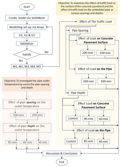
Figure 1.
Research flow chart for this study.
3.1. Numerical Model Development
Three models (V1, V2, and V3) as per Figure 2 were created using SolidWorks with different pipe spacing (200 mm, 150 mm, and 100 mm) for the purpose of validation based on the models by Basheer et al. [6].
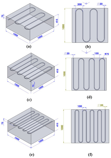
Figure 2.
Control model validation: (a) V1, (c) V2, and (e) V3; isometric view: (b) V1, (d) V2, and (f) V3 top view.
In the present study, Models 1 to 5 (M1, M2, M3, M4, and M5) were created with the same dimensions as the verification models (1000 mm × 1000 mm × 250 mm depth with a pipe diameter of 20 mm), while keeping the diameter and thickness of the pipe unchanged, with a change in the distance between the pipe from 100 mm to 200 mm. The pipe depth between 85 mm to 50 mm from the surface of the pipe to the surface of the concrete was defined. The details of the setup are tabulated in Table 2. To determine the influence of the presence and absence of a pipe, as well as the impact of different depths and lengths of the pipe, a series of loading tests were conducted on various models.
Table 2.
Description of the research models.
3.2. Properties of Materials
The definition of the materials included in the research is important to give a clear perception of the materials used and their properties. The following materials were used: concrete, copper, and liquid water. Table 3 shows the properties of the concrete used to harvest the solar energy, as well as the properties of pipe and fluids used in the energy harvesting—where the diameter of the tube was 20 mm, the thickness was 0.02 mm, and the thermal conductivity of the pipe was 380 w/mK—and other characteristics of the models [6,22].
Table 3.
Properties of the concrete, pipe, and fluid [22].
3.3. Ansys Modeling Finite Element Simulation Using Ansys Workbench 19.2
The concrete pavement layer was designed as an isotropic material and a three-dimensional material and we studied the effects of mechanical stress and temperature distribution with respect to the surface of different temperatures according to the finite element method (FEM). In this study, the main purpose of using the ANSYS Workbench using the finite element method is to pre-examine the simulation studies with the characteristics of the data for the stage of applying the improvements for outlet temperature and verifying them, in addition to studying the mechanical properties of the concrete under the influence of loads according to the specified standards on the concrete pavement. Furthermore, the concrete material was assigned with nonlinear and thermal strain effects. The nonlinear effect is assigned because it is recommended for complex geometry [23]. Moreover, since this study involves measuring deformation, the thermal effect on the material is taken into account by considering the thermal strain [24]. Table 4 presents the initial and boundary conditions along with the parameters for the model.
Table 4.
Details for inputting thermal analysis in COMSOL.
The number of nodes obtained for the numerical model meshing is 472,900, with 1,986,448 elements. Figure 3 shows the model meshing of the pavement used for simulation, where the whole body mesh (concrete model) was assigned as tetrahedral and the pipe model mesh was assigned as a structured hexahedral mesh.
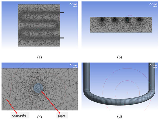
Figure 3.
Model meshing: (a) top view, (b) side view, (c) close-up side view, and (d) pipe mesh.
3.3.1. Boundary Condition
The distance between the pipes (200 mm and 100 mm), the pipe depth with a fixed diameter of 20 mm and a flow of 0.05 kg/s with dimensions of 1 m2. The effect of traffic loads on the model was also evaluated in terms of the effect of stress and strain and the extent of the effects that can be caused by the presence of pipes inside the concrete. Structural response load (vehicle static load) was analyzed on concrete pavement. The vehicle static load was set as the BZZ-100 equivalent standard axle load (ESALs) [18]. As the edge effect was disregarded, the critical load position was identified as the center of the concrete slab.
3.3.2. Initial Condition
The initial temperature condition was set at 40 °C at the pavement surface, with a flow velocity as shown in Figure 4a,b.
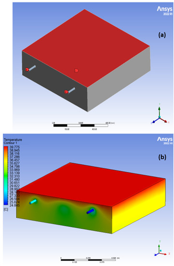
Figure 4.
(a) Inlet and outlet water pipe with heat concrete surface; (b) heat distribution through the concrete.
3.4. Load Set-Up
To study the load effect and mechanical response of the concrete pavement and embedded pipes, a standing vehicle load according to AASHTO was determined at 70 KN for a single axial load, with the tire area shown in Figure 5a–d applied to the pavement surface.
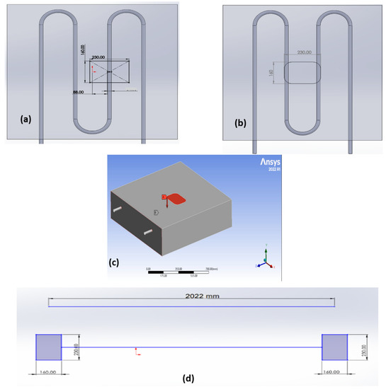
Figure 5.
(a) Area of tire and applied load location at pipe; (b) area of tire and applied load location at center of concrete; (c) direction of applied static load at surface; and (d) single axle and area of tire.
4. Model Validation
Figure 6 and Figure 7 show the relationship between the different pipe spacing, which were 200 mm, 150 mm, and 100 mm, with a constant surface depth of 75 mm against the temperature distribution. From the simulation results, pipes with a spacing of 100 mm show a higher output temperature of 326 K, where the outlet temperature increased by 3% when the spacing distance was reduced from 200 mm to 150 mm, and increased by 6% when the pipe spacing was changed from 150 mm to 100 mm. This shows that the reduction in spacing was consequent in the increase in heat production efficiency, as well as the higher outlet temperature. The results agreed with the literature [6], where a similar model with 100 mm pipe spacing collected a temperature of 322 K, with a 3% difference from the results obtained in this study. This demonstrates that the simulation model used in this study is reliable.
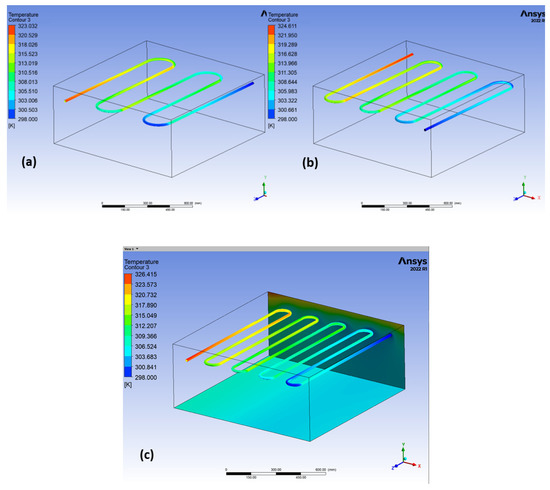
Figure 6.
The temperature outlet with various pipe spacing: (a) V1:200 mm, (b) V2:150 mm, and (c) V3:100 mm.
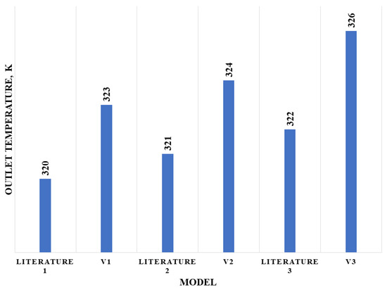
Figure 7.
Tabulated data of outlet temperature at different pipe spacing.
5. Results and Discussion
In this section, we present the outcomes of Models 1 to 6, which examine the impact of pipe spacing and depth on outlet temperature, as well as the influence of traffic load on the behavior of concrete and pipes with varying spacing and depths when subjected to loading.
5.1. Effect of Pipe Spacing on the Outlet Temperature
The distances between pipes have an effective effect on the outlet temperature. The results show that the smaller the space between pipes, the higher the temperature while maintaining the depth of the pipes and the mass flow rate constant. The outlet temperature increases as much as 0.4%, from 28.9 °C to 29.1 °C, when the pipe spacing reduces from 200 mm to 100 mm as shown in Figure 8a,b.
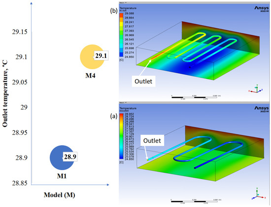
Figure 8.
Comparison of temperature outlet with different pipe spacing: (a) M1:200 mm; (b) M4:100 mm at a fixed depth of 85 mm.
5.2. Effect of Pipe Depth on Outlet Temperature
Figure 9 shows the effect of the outlet temperature on the depth of the pipe and the spacing between the pipes. The depth of the pipe affects the external temperature, where the smaller the depth of the pipe, the higher the temperature while keeping the distance between the pipes 200 mm and the flow rate at constant. The results show an outlet temperature reading of 28.9 °C for a depth of 85 mm. By reducing the depth to 60 mm it became 29.5 °C with an increase of 1.9%, while it increased by 4.5% when the depth was further reduced from 85 mm to 50 mm, as is shown in Figure 8. The temperature increased as the pipes approached the surface [25].
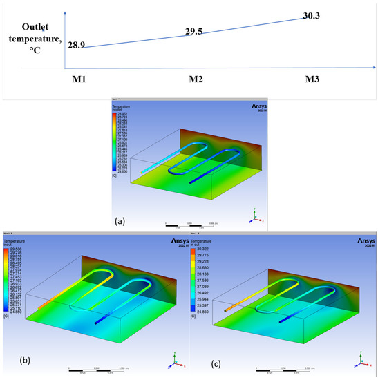
Figure 9.
Various depths of pipe on the outlet temperature with a constant spacing of 200 mm: (a) M1, (b) M2, and (c) M3.
5.3. Effect of the Traffic Load on Concrete Pavement and Pipes
This section examines the effect of traffic load on the surface of the concrete pavement and the effect of traffic load on the embedded pipe at various spacing and depths.
5.3.1. Effect of Traffic Load on Concrete Pavement Surface with Different Spacing between the Pipes
The deformation on the pipe slightly increases with the decrease in the spacing between the pipes, where the deformation was 0.00502 mm when the spacing was 200 mm, and 0.00509 mm when the spacing was 100 mm as shown in Figure 10 and Figure 11. When the distance between the pipes decreased from 200 mm to 100 mm, the stress value on the pavement surface decreased from 0.6188 MPa to 0.6186 MPa.
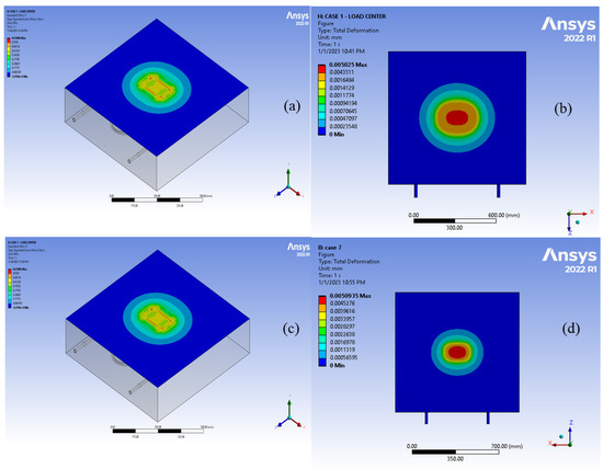
Figure 10.
Equivalent stress (a,c) and (b,d) deformation of the surface with various pipe spacing.
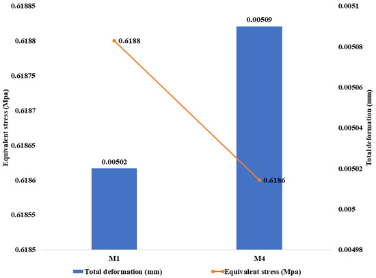
Figure 11.
Equivalent stress and deformation of the surface with various pipe spacing: M1:200 mm and M4:100 mm.
5.3.2. Effect of Traffic Load on the Pipe with Different Spacing between the Pipes
Table 5 shows an increase in the deformation on the pipe surface by 26% when the distance between the pipe reduces from 200 mm (M1) to 100 mm (M4) at a depth of 85mm. Table 5 shows the change in the strain when changing the pipe spacing from 200 mm to 100 mm, where the increase in the strain was 17%. As for the stress, it was also affected when reducing the spacing distance; the stress increased by 33% as shown in Table 5. This shows that spacing between the pipes affected the mechanical response of the concrete and possibly caused failure to the surface of the concrete and the embedded pipe [26].
Table 5.
Comparing the deformation and stress experienced on the pipe as the pipe spacing was reduced from 200 mm to 100 mm.
5.3.3. Effect of Traffic Load on the Pipe with Different Pipe Depths
Figure 12 shows the value of deformation that occurred on the pipe when loading, where it can be seen that the value of deformation in the pipe increased from 0.0032 mm to 0.0046 mm when reducing the depth of the pipe from the concrete surface from 85 mm to 50 mm and with a distance between the pipes fixed at 200 mm. The figure also shows that the equivalent stress value from the analysis results increased by reducing the depth of the pipe from 5.21 MPa at a pipe depth of 85 mm to 6.06 MPa when reducing the depth to 60 mm with an increment of 14%, and increased by 36% when the depth changed from 60 mm to 50 mm as shown in Figure 12.
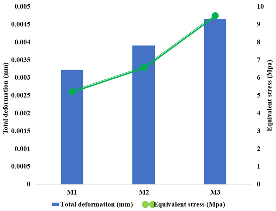
Figure 12.
Comparing the deformation and stress experienced on the pipe at different depths.
5.3.4. Effect of Traffic Load on Concrete Pavement Surface with Different Depths of Pipe
The findings showed that the pavement surface experienced deformation, including the energy collection pipes, under traffic loads and was greater by 3.3% than the deformation of the conventional pavement surface with respect to the static load of the vehicle. The deformation increased by 0.5% when the pipe depth was reduced to 60 mm, as shown in Table 6. As the depth of the pipe was located further away from the surface of the pavement, the deformation increased. This shows that the presence and location of pipe have a direct effect on the deformations that occur in the surface of the pavement. Studies on a road pavement solar collector using 3D Computational Fluid Dynamics (CFD)–finite element model (FEM) also indicate that the incorporation of heat pipes has a notable impact on the mechanical behavior of the pavement structure as a whole [18].
Table 6.
Comparing total deformation, strain, and stress on the surface with different depths (control, M1:85 mm, and M2:60 mm).
In addition, from Table 6, the presence of pipe (M1) in the concrete reduces the stress and strain experienced on the concrete surface as the traffic load was applied by 25.61% and 24.82%, respectively, compared with no pipes in the concrete (M6). It was observed that there were small reductions in stress and strain as the depth of the pipe moved from 85 mm to 60 mm. The study found that the behavior of concrete pavement was similar to that of asphalt pavement in the literature. It indicated that, under vehicle load, the pipes in the pavement helped to reduce the deformation and improve the mechanical properties of the surface layer, regardless of the type of pavement material used. A simulation study employing vehicle–temperature coupled loading on hydronic asphalt pavement demonstrates an improvement in the pavement’s rutting resistance performance relative to conventional pavement [27].
6. Discussion
Figure 13 illustrates that the maximum temperature among the 5 models is 30.3 °C (M3) for a tube spacing of 200 mm and a depth of 50 mm from the surface. However, it is important to consider the impact of the load on the concrete surface and the embedded pipes. As previously stated, the presence of the pipe reduced the impact of pressure on the surface as it approached the pavement. However, the pressure on the pipe increased so rapidly that it could damage the pipe, leading to damage to the pavement surface as well. Model No. 4, with a depth of 85 mm and a spacing distance of 100, has good results and light damage because the impact load is low compared with Models No. 3 and 5 in terms of impact, and the outlet temperature is higher than Model No. 1 as shown in Table 7.
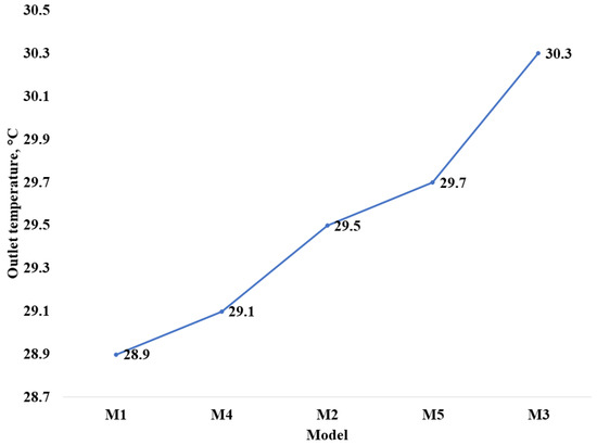
Figure 13.
Outlet temperature with various depths and pipe spacing.
Table 7.
Summarize of effect load with outlet temperature, stress on surface, and stress on pipe.
7. Conclusions
This paper carried out ANSYS modeling of the pavement solar collector made from concrete. The modeling purpose was to investigate the pipe outlet temperature by varying the pipe spacing and depth and to examine the effect of traffic load on the surface of the concrete pavement and the effect of traffic load on the embedded pipe at various spacing and depths. In summary, the findings lead to the following conclusions:
- The deformation increased for traditional pavement compared with integrated pipe under similar conditions and load.
- Deformation increases on both pavement and merged pipe with decreasing depth and spacing of the pipes, and the stress on the pipe increases while decreasing the depth and distance of the pipe.
- A good criterion for a pavement solar collector system is to maximize outlet temperature while minimizing effects on traffic loading.
- The maximum outlet temperature occurs at a depth of 50 mm and a spacing of 100 mm, but the significant impact of traffic load poses a threat to the pavement’s structural integrity at this depth.
- Model 4 with a distance of 100 mm and a depth of 85 mm is acceptable for the external temperature as it decreases by only 3.9%, and the effect of the load was less by 51% compared with the model that provides the highest outlet temperature.
- Optimizing pipe depth and spacing for maximum temperature extraction while considering the concrete’s structural performance using numerical simulation is essential to prove the feasibility of applying concrete pavement for a solar collector.
Author Contributions
Writing—original draft preparation, M.A.A.; writing—review and editing, M.I.N. and M.S.A.B.; supervision, Z.I.; investigation, S.M.M.S.A.F. and N.M.Z.; methodology, A.S.; validation, M.H.Z. and N.A.R. All authors have read and agreed to the published version of the manuscript.
Funding
This publication was funded by BOLD Refresh with support from BOLD HICOE 2020 Grant No. J510050002/HICOE05 sponsored by the Universiti Tenaga Nasional UNITEN.
Informed Consent Statement
Not applicable.
Data Availability Statement
Data are available in a publicly accessible repository that does not issue DOIs.
Acknowledgments
The authors gratefully acknowledge IRMC UNITEN and the Institute of Energy Infrastructure (IEI) for the laboratory facilities.
Conflicts of Interest
The authors declare no conflict of interest.
References
- Senevirathne, D.M.; Jayasooriya, V.M.; Dassanayake, S.M.; Muthukumaran, S. Effects of Pavement Texture and Colour on Urban Heat Islands: An Experimental Study in Tropical Climate. Urban Clim. 2021, 40, 101024. [Google Scholar] [CrossRef]
- Abbas, F.A.; Alhamdo, M.H. Thermal Performance of Asphalt Solar Collector by Improving Tube and Slab Characteristics. Int. J. Thermofluids 2023, 17, 100293. [Google Scholar] [CrossRef]
- Ebrahim Abu El-Maaty, A. Temperature Change Implications for Flexible Pavement Performance and Life. Int. J. Transp. Eng. Technol. 2017, 3, 1–11. [Google Scholar] [CrossRef]
- Adl-Zarrabi, B.; Mirzanamadi, R.; Johnsson, J. Hydronic Pavement Heating for Sustainable Ice-Free Roads. Transp. Res. Procedia 2016, 14, 704–713. [Google Scholar] [CrossRef]
- Mirzanamadi, R.; Hagentoft, C.E.; Johansson, P.; Johnsson, J. Anti-Icing of Road Surfaces Using Hydronic Heating Pavement with Low Temperature. Cold Reg. Sci. Technol. 2018, 145, 106–118. [Google Scholar] [CrossRef]
- Basheer Sheeba, J.; Krishnan Rohini, A. Structural and Thermal Analysis of Asphalt Solar Collector Using Finite Element Method. J. Energy 2014, 2014, 602087. [Google Scholar] [CrossRef]
- Songok, J.; Mäkiranta, A.; Rapantova, N.; Pospisil, P.; Martinkauppi, B. Numerical Simulation of Heat Recovery from Asphalt Pavement in Finnish Climate Conditions. Int. J. Therm. Sci. 2023, 187, 108181. [Google Scholar] [CrossRef]
- Ghalandari, T.; Baetens, R.; Verhaert, I.; Nasir, D.S.N.M.; Van den Bergh, W.; Vuye, C. Thermal Performance of a Controllable Pavement Solar Collector Prototype with Configuration Flexibility. Appl. Energy 2022, 313, 118908. [Google Scholar] [CrossRef]
- Johnsson, J.; Adl-Zarrabi, B. A Numerical and Experimental Study of a Pavement Solar Collector for the Northern Hemisphere. Appl. Energy 2020, 260, 114286. [Google Scholar] [CrossRef]
- Dakessian, L.; Harfoushian, H.; Habib, D.; Chehab, G.R.; Saad, G.; Srour, I. Finite Element Approach to Assess the Benefits of Asphalt Solar Collectors. Transp. Res. Rec. J. Transp. Res. Board 2016, 2575, 79–91. [Google Scholar] [CrossRef]
- Patil, V.A.; Sawant, V.A.; Deb, K. 2-D Finite Element Analysis of Rigid Pavement Considering Dynamic Vehicle-Pavement Interaction Effects. Appl. Math. Model. 2013, 37, 1282–1294. [Google Scholar] [CrossRef]
- Zineddin, M. Simulation of Reinforced Concrete Slab Behavior under Impact Loading. In Proceedings of the AEI 2008 Conference—AEI 2008 Building Integration Solutions, Denver, CO, USA, 24–27 September 2008; Volume 328. [Google Scholar] [CrossRef]
- Li, Z.; Shen, A.; Long, H.; Guo, Y.; He, T. Dynamic Deterioration of Strength, Durability, and Microstructure of Pavement Concrete under Fatigue Load. Constr. Build. Mater. 2021, 306, 124912. [Google Scholar] [CrossRef]
- Pasetto, M.; Baliello, A.; Giacomello, G.; Pasquini, E. Mechanical Feasibility of Asphalt Materials for Pavement Solar Collectors: Small-Scale Laboratory Characterization. Appl. Sci. 2022, 13, 358. [Google Scholar] [CrossRef]
- Pasetto, M.; Baliello, A.; Giacomello, G.; Pasquini, E. Rutting Behavior of Asphalt Surface Layers Designed for Solar Harvesting Systems. Materials 2022, 16, 277. [Google Scholar] [CrossRef]
- Nasir, D.S.; Pantua, C.A.J.; Zhou, B.; Vital, B.; Calautit, J.; Hughes, B. Numerical Analysis of an Urban Road Pavement Solar Collector (U-RPSC) for Heat Island Mitigation: Impact on the Urban Environment. Renew. Energy 2021, 164, 618–641. [Google Scholar] [CrossRef]
- Zaim, E.H.; Farzan, H.; Ameri, M. Assessment of Pipe Configurations on Heat Dynamics and Performance of Pavement Solar Collectors: An Experimental and Numerical Study. Sustain. Energy Technol. Assess. 2020, 37, 100635. [Google Scholar] [CrossRef]
- Zhou, B.; Pei, J.; Richard Hughes, B.; Nasir, D.S.N.M.; Vital, B.; Pantua, C.A.J.; Calautit, J.; Zhang, J. Structural Response Analysis of Road Pavement Solar Collector (RPSC) with Serpentine Heat Pipes under Validated Temperature Field. Constr. Build. Mater. 2021, 268, 121110. [Google Scholar] [CrossRef]
- Farzan, H.; Zaim, E.H.; Ameri, M.; Amiri, T. Study on Effects of Wind Velocity on Thermal Efficiency and Heat Dynamics of Pavement Solar Collectors: An Experimental and Numerical Study. Renew. Energy 2021, 163, 1718–1728. [Google Scholar] [CrossRef]
- Al-Jabari, M.; Al-Rashed, R.; Ayers, M.E.; Clement, D. Materials Selection and Proportioning for Watertight and Durable Concrete. In Integral Waterproofing of Concrete Structures; Elsevier: Kidlington, UK, 2022; pp. 109–134. [Google Scholar]
- Wang, H. Life-Cycle Analysis of Repair of Concrete Pavements. In Eco-Efficient Repair and Rehabilitation of Concrete Infrastructures; Elsevier: Kidlington, UK, 2018; pp. 723–738. [Google Scholar]
- O’Hegarty, R.; Kinnane, O.; McCormack, S.J. Concrete Solar Collectors for Façade Integration: An Experimental and Numerical Investigation. Appl. Energy 2017, 206, 1040–1061. [Google Scholar] [CrossRef]
- Sabău, M.; Oneţ, T. Nonlinear Concrete Behaviour. J. Appl. Eng. Sci. 2011, 1, 55–60. [Google Scholar]
- ANSYS Intro to Thermal Strain—Lesson 1. Available online: https://courses.ansys.com/index.php/courses/thermal-strain/lessons/intro-to-thermal-strain-lesson-1/ (accessed on 5 May 2023).
- O’Hegarty, R.; Kinnane, O.; McCormack, S.J. Parametric Investigation of Concrete Solar Collectors for Façade Integration. Sol. Energy 2017, 153, 396–413. [Google Scholar] [CrossRef]
- Aboudi, J.; Arnold, S.; Bednarcyk, B. Failure Criteria and Margins of Safety. In Practical Micromechanics of Composite Materials; Elsevier: Oxford, UK, 2021; pp. 161–214. [Google Scholar]
- Zhu, X.; Zhang, Q.; Chen, L.; Du, Z. Mechanical Response of Hydronic Asphalt Pavement under Temperature—Vehicle Coupled Load: A Finite Element Simulation and Accelerated Pavement Testing Study. Constr. Build. Mater. 2021, 272, 121884. [Google Scholar] [CrossRef]
Disclaimer/Publisher’s Note: The statements, opinions and data contained in all publications are solely those of the individual author(s) and contributor(s) and not of MDPI and/or the editor(s). MDPI and/or the editor(s) disclaim responsibility for any injury to people or property resulting from any ideas, methods, instructions or products referred to in the content. |
© 2023 by the authors. Licensee MDPI, Basel, Switzerland. This article is an open access article distributed under the terms and conditions of the Creative Commons Attribution (CC BY) license (https://creativecommons.org/licenses/by/4.0/).