1. Introduction
At present, the research on the parabolic partial differential equation is becoming more and more prominent, and its important mathematical structure model and powerful physical background have attracted the attention of many scholars. It has been widely used in practical problems such as heat transfer, transportation, chemical reactions, etc. For example, in reference [
1], in the optimization of innovative recycling chemical process, the partial differential equation model is used to solve the case deviation of the countercurrent reactor involving conflicting conversion rates and energy, and their performance is compared with the classical weighted sum method. In reference [
2], the partial differential heat equation is designed by using the feedback boundary controller of an unstable system. An unstable linear term is added to the right of the heat equation, and then, the stability of the system is proved by constructing a Lyapunov function, in reference [
3]; the model of vehicle traffic and the crowd phenomenon is established by using a partial differential equation, and then, the partial differential model is optimized by a regression analysis. In recent years, the numerical analysis of unsteady flow and heat transfer has also attracted the attention of many scholars [
4]. As one of the numerical solutions to partial differential equations, the spectral method has a unique weighted margin method and higher computational accuracy, which is incomparable to the conventional finite element method (FEM) [
5,
6], finite volume method (FVM) [
7,
8] and the finite difference method (FDM) [
9]. According to different related test functions, it mainly includes the Galerkin spectrum method, the Petrov–Galerkin spectrum method, and the configuration point spectrum method. According to the superiority of the spectral method, this paper solves the two-dimensional parabolic partial differential heat conduction equation. The Galerkin spectral method is used for approximation in space direction and the central difference scheme for approximating in time direction, respectively. Thus, the numerical algorithm for solving the partial differential equation is named the “Galerkin spectral method” (see, e.g., [
10]).
A large number of experimental conditions have confirmed the effectiveness and feasibility of solving partial differential equations with the central difference Galerkin spectrum method. However, there is a slight shortcoming: when using the central difference scheme propulsion technique to solve partial differential groups, the convergence of the algorithm depends on the selection of different time intervals and in the algorithm process. It is necessary to carry out a time-effective promotion cycle for all defined time steps. In the cycle process of each time layer, the system equations that have been formed must be iterated once. When the number of grids drawn is large, the degree of freedom of the corresponding unknown element is too large, and the load of the computer solving the equation is excessive, which leads to the continuous accumulation of errors in the process of the computer executing the program. Even if the classical central difference iteration scheme is selected as the best, the floating-point saturation of error accumulation will be too high after several steps of calculation, leading to the failure of convergence of the numerical iteration scheme and the failure to reach the expected numerical solution. In this case, it is very necessary to construct a kind of reduced-order extrapolation algorithm with a strong convergence error accuracy and with few degrees of freedom. It is one of the reasons why the classical central difference Galerkin spectral method needs a POD reduced-order extrapolation when solving two-dimensional parabolic partial differential equations.
The best orthogonal decomposition technique is a fast-computing method, which can approximate the high dimensional physical process and accurately describe the high dimensional data in the low dimensional space [
11,
12,
13]. The POD method was first proposed by Karhunen (1946) and Loeve (1945) and has been used in many fields. In statistics, this method is called the principal component analysis (PCA) [
14]. This method has also been applied in meteorology and is called the empirical orthogonal function method [
15]. Lumely first applied the eigenorthogonal decomposition method to large vortex-dependent structures that capture turbulence [
16,
17]. In recent years, the POD method combined with the Galerkin projection method has been used in a dimensional-reduction solution of fluid differential equations [
18,
19]. In reference [
20], Ramo combined the POD method and the flux conservation method (FMP) to calculate the dimension reduction of differential equations. Hu combined the POD method with the spline interpolation method in reference [
21]. The POD method is also used in the study of cross-scale problems. Du and Hu used the POD method to study cross-scale problems in air cooling systems [
22]. Hazenber Martijn et al. established a POD–Galerkin dimensional-reducing interpolation algorithm model for two-dimensional plate heat conduction [
23].
Although the above literature combined the POD method and the Galerkin method to deal with parabolic problems, it did not simplify the calculation of FVM, FEM and FDM for parabolic problems, and their method took the numerical solutions of all the time difference nodes as sample points (called naPshot, namely, instantaneous image). In this paper, the classical Galerkin projection space is replaced by the Galerkin subspace spanned by a POD basis function, and the algorithm format with a higher dimension is simplified into the POD extrapolation spectral method iteration format with a low dimension. In particular, it can be seen from theoretical analysis that the scheme does not need to take all the numerical solutions of time difference nodes as instantaneous images, but only needs to take a few numerical solutions of time difference nodes as instantaneous images to ensure a high enough precision, thus reducing the calculation amount of solving the POD basis. Therefore, the method in this paper is the improvement and innovation of the existing method.
2. The Mathematical Model
The governing equation of the two-dimensional unsteady heat conduction problem in rectangular coordinates is Equation (1) (See, e.g., II of Chapter VI of Reference [
12]):
where
,
,
represents heat transfer temperature,
is the material density (kg/m
3),
is the specific heat capacity of the material
is the thermal conductivity of the
and
is the term function of the known radiation heat source. Both
and
are initial conditions, T is the total time period.
Boundary condition:
In order to facilitate the programming, the three kinds of boundary conditions are uniformly expressed as the expression of heat flux. (see, e.g., II of Chapter II of reference [
24]).
where in the first boundary condition
b1 = 1,
b2 = 0,
b3 = 0; in the second boundary condition
b1 = 0,
b2 = 1,
b3 = 0; in the third boundary condition
b1 = 0,
b2 = 0,
b3 = 1.
In the second boundary condition,
q is the heat flux, and in the third boundary condition,
is the fluid temperature. In the analysis of this article, it considers the position of adjacent points around the boundary. It is generally assumed that the line between the boundary points and its adjacent points are perpendicular to each other. Thus, the discrete expression of Equation (2) can be obtained:
In Equation (3), is the number of the valid boundary node, the number of its adjacent internal nodes is marked as , and is the effective distance between and nodes.
3. Iterative Algorithm of Two-Dimensional Central Difference Galerkin Spectral Method
Assume that is expressed as a time step, and finite sequences and represent nodes in the x and y directions, respectively.
Here, Chebyshev–Gauss–Lobatto type configuration points are selected as space nodes.
By combining the theory of the Galerkin spectrum method and the temperature field function at the time node
can be constructed:
where both
and
are Chebyshev orthogonal polynomials (see, e.g., [
25]), and
is the spectral coefficient, when
,
can replace
, the effective approximate discrete form of temperature field
on the space node is obtained. That is, the first discrete form:
In addition, from Chebyshev’s forward discrete transformation, the following equation can be obtained:
Thus, the second discrete form of the effective approximation function can be obtained:
where
as well as,
where
Furthermore, the recurrence relation of Chebyshev polynomials is
From (13), the following expressions for the first derivative and the second derivative of Chebyshev polynomials can be obtained.
Obviously, from (11) and (14), it is easy to obtain the approximation function of the second partial derivative of the temperature field in the
x direction and y direction on the Chebyshev–Gauss–Lobatto configuration point.
In addition, the first-order partial derivative of the temperature field with respect to the time direction can also be obtained by the central difference approximation method.
Assume that , , , , .
Here, , .
Therefore, it is easy to obtain the following according to the above conditions. The exact solution and approximate solution of Equation (1) on the Chebyshev–Gauss–Lobatto type collocation points can be replaced by sets , and , , , , .
The following matrix relations can be obtained.
The element of matrix
is
, and Matrix
can be expressed as follows:
Similarly, the matrix of
can also be expressed by the above formula.
From the matrix given above, it is not difficult to find the Galerkin spectral method iterative format of the following temperature field
.
Here, both matrix C and matrix D are
order matrices, and
4. Error Estimates of Iterative Schemes for the Galerkin Spectral Method
Using Taylor’s series expansion, we get
From (19) and (20), we can get
Theorem 1. The solution component of the iterative scheme (19) of the central difference Galerkin spectral method has the following error estimates: where is the usual norm of the vector. As for the proof of this theorem, which can be given a detailed answer from Equation (22) and reference [
25], and we can obtain that its stability condition satisfies
.
5. Galerkin Spectral Analysis of Two-Dimensional Transient Nonlinear Heat Conduction Equation Based on POD Reduced-Order Extrapolation Structure of POD Base
The selection of the POD basis is very important when the Galerkin spectral method is used to solve transient nonlinear heat conduction problems based on the POD reduced-order dimension extrapolation algorithm. Obtaining the best POD basis can not only ensure the accuracy of numerical calculation results, but also greatly improve the efficiency of experimental simulation. Therefore, it can be seen that the core problem of the POD reduced-order extrapolation method is to find a set of “optimal” orthogonal bases of on the known function space through an iterative calculation. There is no doubt that the so-called “optimization” means that the error generated by the projection of function space onto a finite number of orthogonal bases with relatively low dimensions reaches the minimum. In this way, when using the reduced dimension extrapolation Galerkin spectrum method of the POD method to solve the transient heat conduction problem, it is usually realized through the following steps.
The first step: Construct sample matrix.
Assume
Here,
,
, The initial solution
of
L (
L<<I) is calculated and recorded as a sample. Thus, the solution of the iterative scheme (19) of the classical central difference Galerkin spectral method can be expressed in sets, and the initial solution A of
group can be calculated, which is recorded as the instantaneous image. Next, we will construct a G ×
L-order instantaneous image matrix. That is, as sample matrix
Z.
The second step: SVD decomposition of sample matrix, through SVD decomposition technology (see, e.g., [
26,
27,
28]), the sample matrix can be expressed as:
where
and r = rank(Z),
is the positive singular value of matrix Z in descending order, which is arranged in descending order (
).
is an orthogonal matrix of order G × G,
is the standard orthogonal eigenvector of matrix
, which is arranged in the order of
,
is an orthogonal matrix of order
L ×
L, is the standard orthogonal eigenvector of matrix
, and its arrangement order is the same as
.
Normally, the number of numerical solution components L of the selected Galerkin spectral iteration scheme is smaller than the number of spatial grid nodes G. It can be seen that the order of matrix is smaller than that of , but and have the same non-negative eigenvalues. If necessary, can be renumbered in a descending order to meet the following requirements: .
Here, we first calculate the non-zero eigenvalues and eigenvectors of matrix
, secondly, we use the above relationship to establish Equation (26):
It can be found that the eigenvector of matrix
is
and finally we obtain matrix
and matrix
; here, we assume
and select the first
e positive singular values
of matrix
to construct a diagonal matrix,
and we can obtain (27):
so as to obtain the relationship
.
Third step: Generation of the POD base. We specify that the norm of matrix
Z is
(here
is the norm of vector
). According to the relationship between matrix norm and spectral radius, we know that (28) from [
29] is:
It can be seen that the Galerkin spectral method based on the POD reduced-order extrapolation method should meet the following conditions (29):
The minimum value of the optimization result of Equation (29) means that the basis of the Galerkin spectral method based on the POD algorithm is the maximum projection of the original system on the POD basis.
If mark
is the
i-th column vector of matrix
Z, and
is the i-th column vector of matrix
, then, there is:
where
can be seen as the projection of
on
,
is the inner product of
and
. Moreover, inequality (30) shows a best approximation of
to
, and its error cannot exceed the supremum of
. Thus, it can be obtained that a group of optimal orthonormal bases of matrix Z is
.
6. Galerkin Spectral Method for POD Reduced-Order Extrapolation
According to the essential theory of constructing the POD basis in
Section 4 the standard approximate solution of the
group before the iterative scheme of the central difference Galerkin spectral method can be derived from
, and
is the vector associated with
. Similarly, when
, the numerical solution of the iterative scheme of the central difference Galerkin spectral method is still approximated by the approximate solution of
. At this time,
is replaced by
. Its essence is that the solution of the first
step of the reduced-order central difference scheme is obtained by projecting the solution of the initial
step of the Galerkin spectral method iterative scheme of the central difference of heat conduction onto the POD basis. When the number of iterations is greater than step
, the solution is obtained through finite recursion by completely relying on the POD basis generated in the initial step
of the central difference Galerkin spectral method iteration scheme and the solution after the reduced-order in step
, which reflects the basic principle of the so-called reduced order extrapolation difference algorithm. The unknown vector
represents that the degree of freedom of the iterative scheme of the central difference Galerkin spectral method for the transient nonlinear heat conduction equation is reduced from H to e, and greatly reduces the order. From this, it can be concluded that the iterative format of the reduced-order central difference Galerkin spectral method generated by the least squares operation is (31) (see, e.g., [
30]).
According to the orthogonality idea of the matrix, multiply both sides of Formula (31) by
, and then, obtain the following iterative format of the reduced dimension extrapolation central difference Galerkin spectral method (32):
Before solving the analytic vector (33) of the iterative format of the reduced-order extrapolation central difference Galerkin spectral method, the iterative format (32) must be used to solve the value of
. Next, it is easy to obtain the expression of the approximate solution of the iterative scheme of the reduced-order extrapolation central difference Galerkin spectral method for the POD algorithm of the transient nonlinear heat conduction equation at point
:
Here, m and n still satisfy the inequality: .
In addition, the numerical solutions of iterative schemes (32) and (33) can be expressed as .
Note 1: It is obvious that there are unknown elements involved in each step of the Galerkin spectral method iteration scheme. When the POD reduced-order extrapolation method is used to iterate the format, the unknown elements are reduced from G elements to e elements . It can be seen that the iterative scheme of POD reduced-order extrapolation spectrum method to solve the heat conduction partial differential problem will bring us great advantages. This reflects the advantages of the POD model, namely, fast, accurate and few.
7. Error Estimation of POD Reduced-Order Extrapolation Galerkin Spectral Method
It is necessary to introduce a very important lemma before implementing the iterative format of the reduced-order extrapolation Galerkin method for error estimation.
Lemma 1. The known sequences andare all three non-negative sequences, if there is a relationship between them: ,, and the sequenceis a monotone sequence, then, there must be (positive integer). Next, we will analyze the error of the iterative scheme solution of the POD reduced-order extrapolation Galerkin spectral method.
Here,
fits formula Equation (35)
where,
is the remainder of Formula (35), so there is (36)
Then the error function
de is the solution of the above partial differential Equation (36)
Combining (30) and (37), the following inequality is obtained.
In particular, if
, we can replace
with
in the second equation of equation set (31), then Equation (39) can be obtained:
Then, we made a difference between (19) and (39), and simplified them into
Taking
without affecting the accuracy of the numerical solution, we can obtain the following Equation (42):
At this time, we substitute
into Formula (42), and get:
Assume .
At this time, .
Next, we can list
equations:
For the above
(i − L) formulas, the following formula can be obtained by using the method of accumulation and simplification.
Referring to the conclusion of Lemma 1, it can be known that:
According to the property that the norm is far greater than or equal to the absolute value of the vector element, it is not difficult to know that the numerical solution of the Galerkin spectral method iterative scheme has the following error estimation results.
where
,
, we can get:
It can be seen that the precise solution of the transient nonlinear heat conduction Equation (1) at point
and the numerical solution of the POD reduced dimension extrapolation Galerkin spectral method iteration scheme (34) have the following error estimates:
where
.
Note 2: Looking at the whole process of the iterative format of the POD reduced-order extrapolation Galerkin spectral method, it can be found that the error factor comes from the optimization harvest of the Galerkin spectral method iterative format after dimensionality reduction. In particular, when , the extrapolation process produces factor, it can be said that whether it is necessary to reconstruct the temperature field and replace the POD base completely depends on the variation range of the above two factors. Furthermore, whether the selection of POD reduced-order extrapolation method basis is appropriate requires the following two conditions.
- (1)
In order to ensure that the POD reduced-order extrapolation method has a small error in the Galerkin spectral method iteration process, the “optimal” POD basis must be selected, that is, meeting the conditions .
- (2)
If , we need to obtain a new POD base, if there is a factor that makes true, this shows that the POD reduced-order iteration is convergent, and the original POD basis remains.
8. Algorithm Implementation of Iterative Scheme of Reduced-Order Extrapolation Galerkin Spectral Method
The implementation of the algorithm of iterative formats (32) and (33) of the reduced-order extrapolation Galerkin spectral method can be completed in the following five steps [
31,
32,
33].
Step 1: We can select spatial nodes as Chebyshev–Gauss–Lobatto type configuration points and construct a Galerkin spectral iteration format reasonably based on the initial time step , then, calculating the initial L-step solution vector and definition:
Step 2: We can build the sample matrix , and calculate the eigenvalues and eigenvectors of matrix . Among them, the feature values are arranged in a descending order, thusly: ().
Step 3: Define condition and determine POD basis by known precision , and is solved by .
Step 4: We can solve the problem by using the iterative format of the reduced-order Galerkin spectral method (31). We can solve (31) by the iterative format of the reduced-order Galerkin spectral method to obtain . The reduced dimension approximate solution of the transient nonlinear heat conduction Equation (1) based on the POD Galerkin spectral method can be obtained.
Step 5: If
just meets the numerical solution of the accuracy condition, otherwise, go back to step 2 and iterate extrapolation again. In addition, the contribution rate and cumulative contribution rate of the characteristic value shall exceed 99.99% and 97.5%, namely:
9. Numerical Simulation Example of POD Reduced-Order Extrapolation Galerkin Spectrum Method
In Equation (1), we take
the initial conditions
Here, we choose H = 100 as the number of spectral approximation basis functions. We agree that the stability conditions are , , , and .
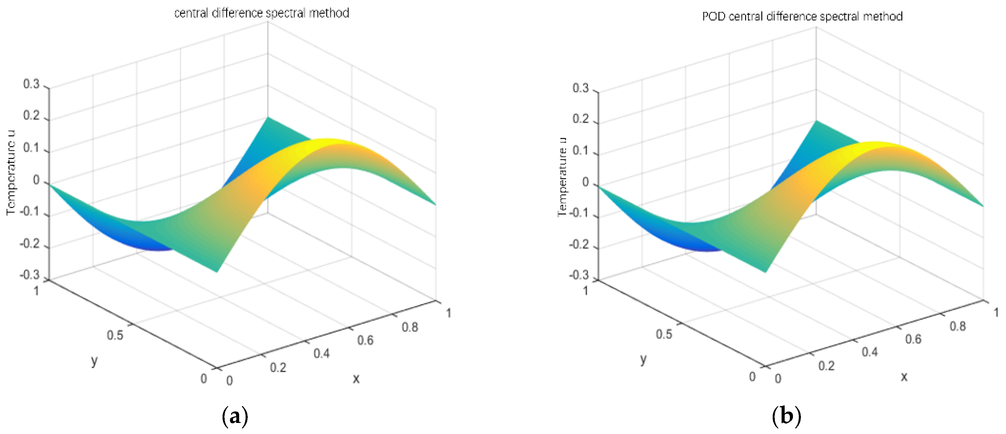
First, according to the iterative scheme (19) of the central difference Galerkin spectral method, the numerical solution of the classical collocation point spectral method is calculated while t = 8 s, and the time steps are taken as , , respectively, then we make figures, which are shown in Figures 2–5, respectively.
Secondly, the numerical solution of the first L = 5 steps at time position node is solved by using the spectral method iteration format (19). We can construct sample matrix . At this time, we can know that the eigenvector of matrix is through expression , stands for .
After calculation, we know that
, which is shown in
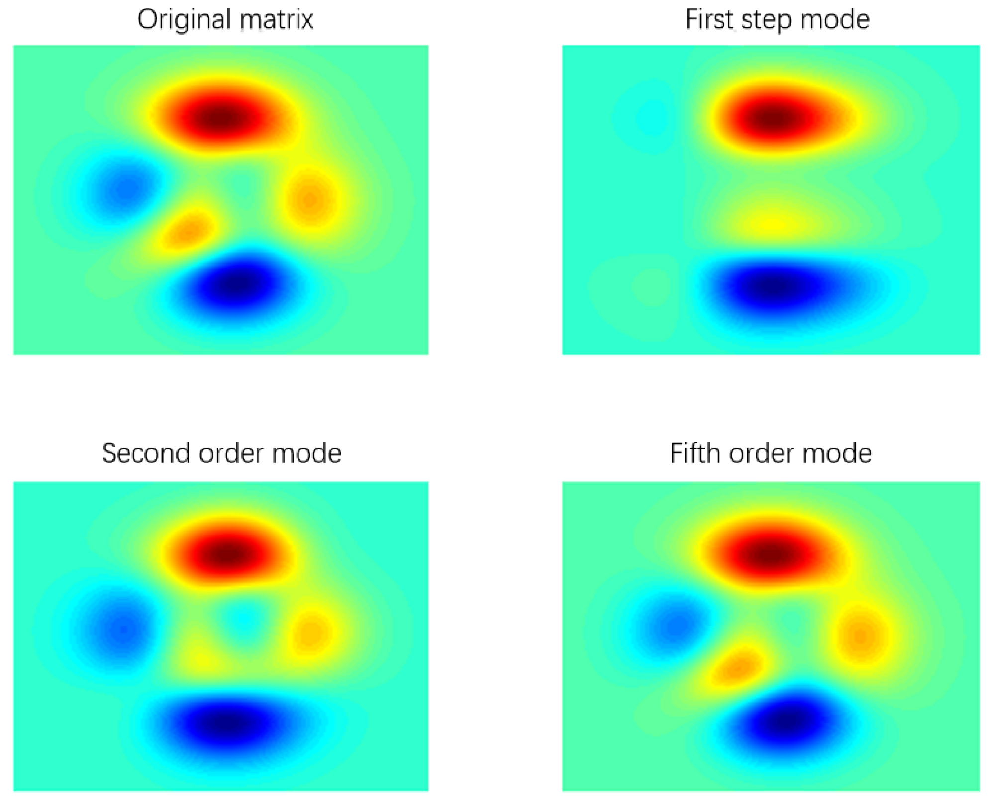
Figure 1; only the first five POD bases can meet the actual accuracy requirements. It is known that it is not necessary to reselect the POD base, and at this time, we can calculate the numerical approximate solution of the reduced dimension spectrum method in the time steps of
,
,
and
then, we can draw their figures, which are shown in
Figure 2b,
Figure 3b,
Figure 4b and
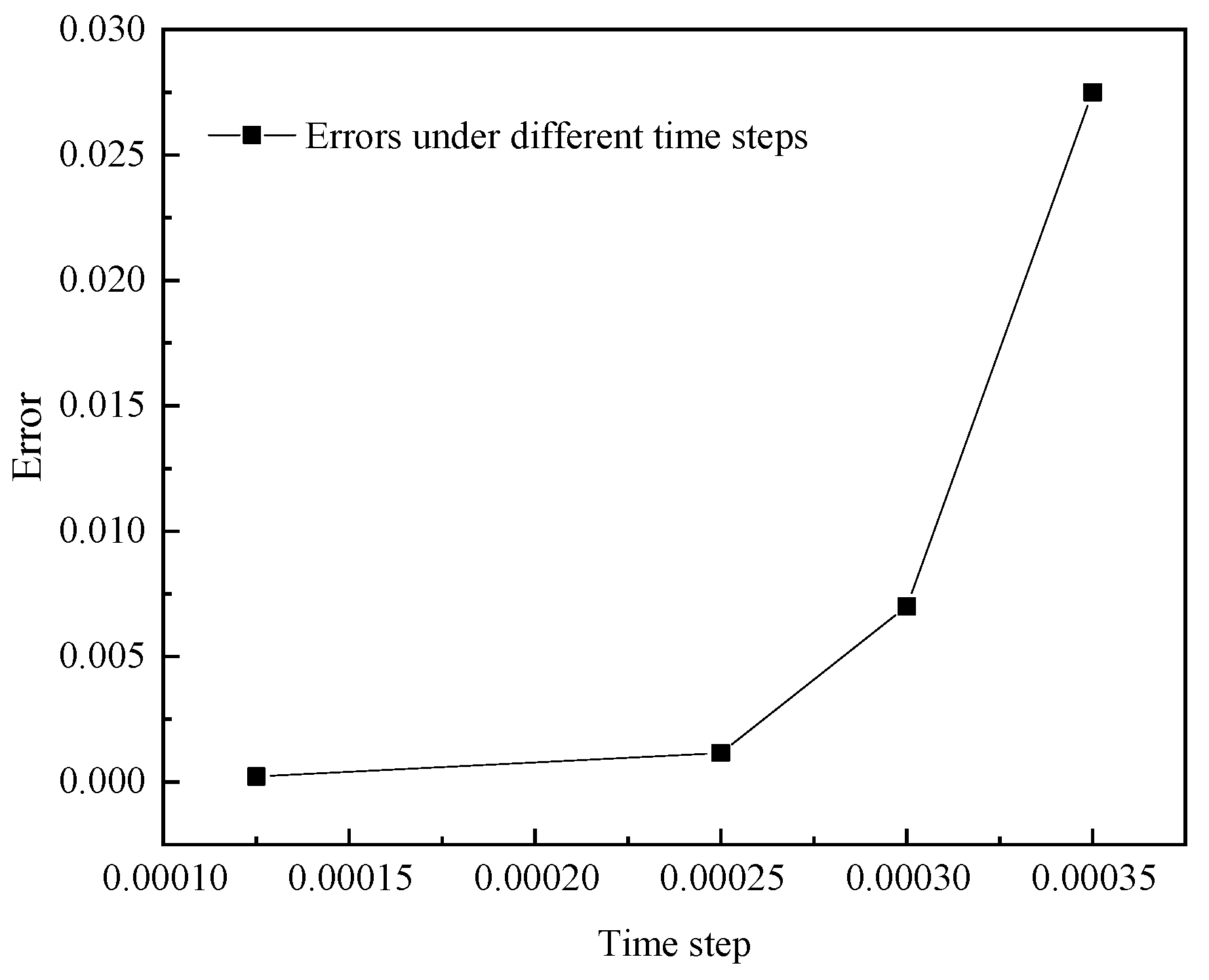
Figure 5b, respectively. Finally, we can use the MATLAB program language to compile the error analysis program of the central difference Galerkin spectrum method and the reduced-order extrapolation central difference Galerkin spectrum method and draw pictures to show.
Note 3: It can be observed from
Table 1 that since the sixth mode, the contribution of eigenvalues to the POD basis is very small, almost close to 0, and the total energy has reached 100%. It can also be seen from
Figure 1 that when the first five singular values are obtained, there is almost no difference between the new matrix and the original matrix, and the abandonment of other singular values after that hardly loses any existing information. This means that only the first five singular values and their corresponding orthogonal matrices U and K are retained, that is, the modal order whose cumulative energy contribution rate reaches 100% is selected as the number of the basis functions. According to the analysis of
Figure 1, we reconstruct the temperature field at different time steps, and the results are shown in figure (b) in
Figure 2,
Figure 3,
Figure 4 and
Figure 5.
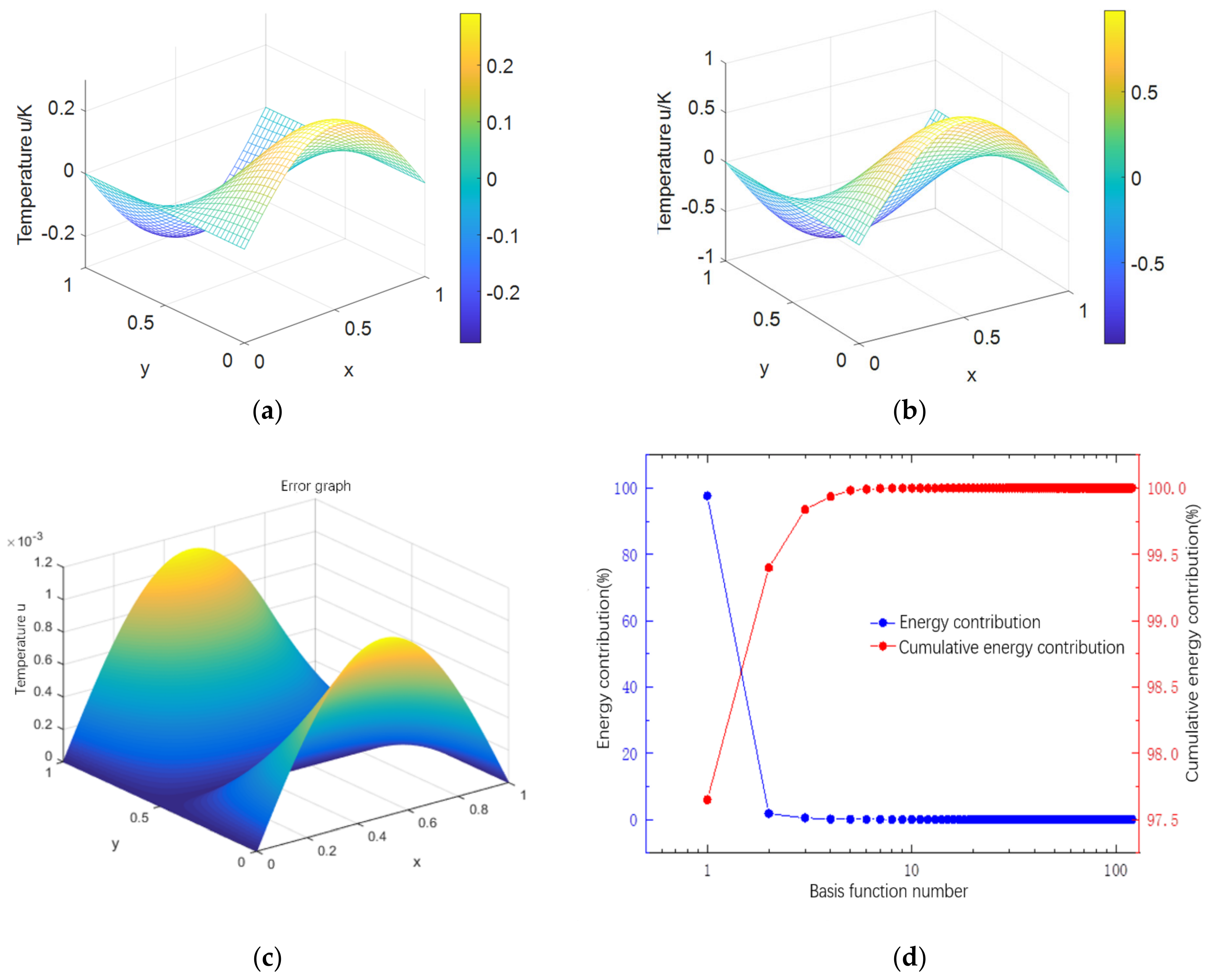
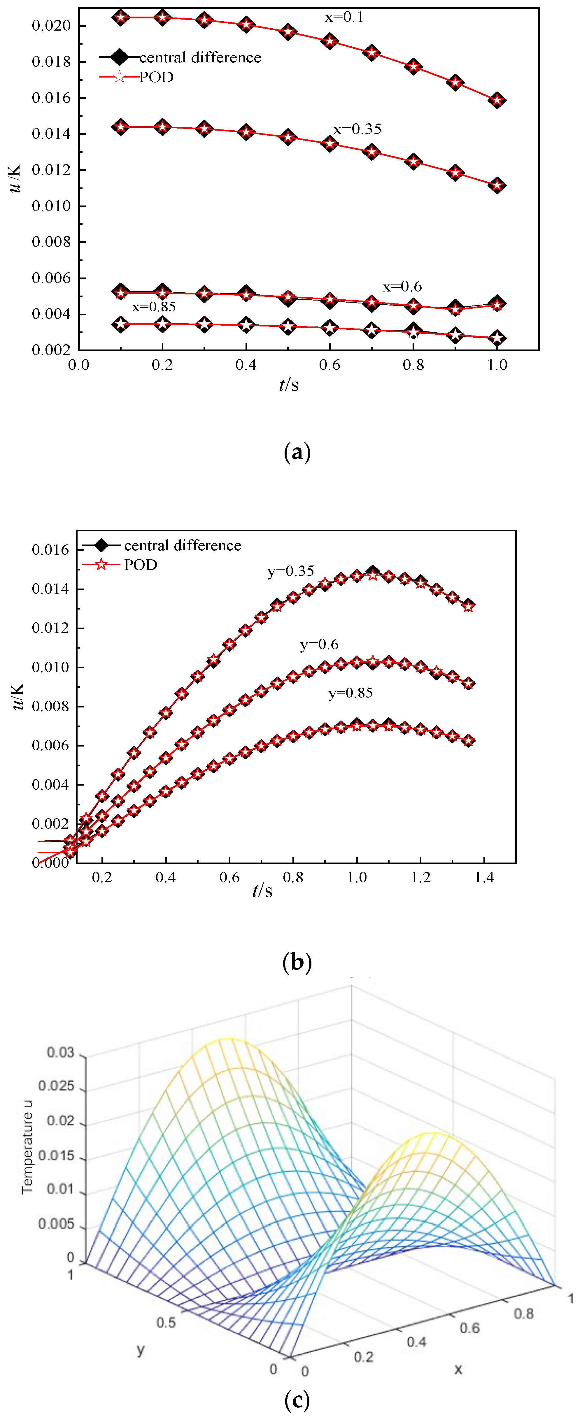
Figure 2 shows a comparison graph between the numerical solutions of POD and the central difference Galerkin spectral method at time step of
when t = 8 s. We can see from
Figure 2c that the temperature reconstruction error is relatively small, and the maximum error cannot exceed
.
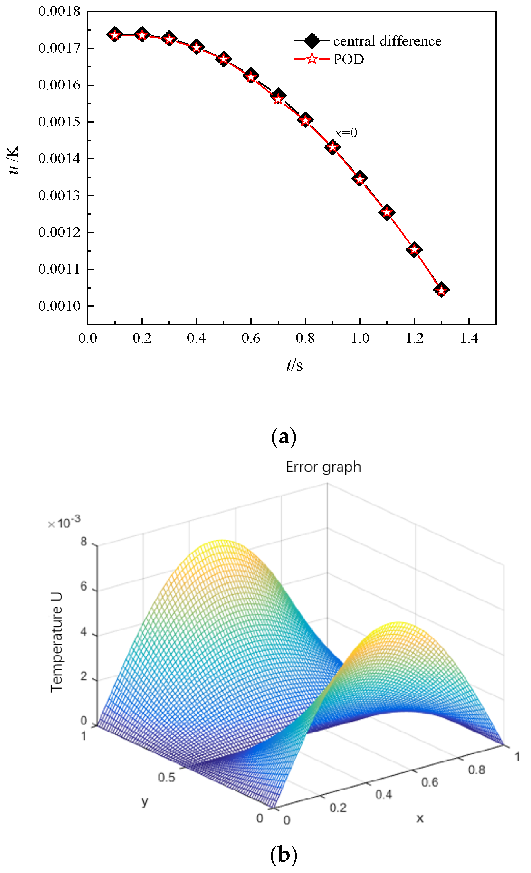
Figure 3 shows the comparison graph between the numerical solutions of POD and the central difference Galerkin spectral method with time step
at t = 8. We can see from
Figure 3c that the temperature reconstruction effect is very good, and the maximum error is less than
.
Table 2 shows the numerical simulation time used for POD extrapolation technology and the central differential Galerkin spectral method at different time steps. From this table, we can see that the time step size in
Figure 2 is the smallest, resulting in a longer consumption time for the central differential Galerkin spectral method, but at this point, the speed of POD extrapolation technology increases faster during the simulation process. This reflects that the POD has a higher computational accuracy when the time step is small.
Table 2 and
Figure 6 show the numerical simulation time of POD extrapolation technique and the central difference Galerkin spectrum method at different time steps. From this table, we can find that the time step in
Figure 2 is the smallest, so the central difference Galerkin spectrum method will consume more time, but during this time, the speed of the POD extrapolation technology is faster in the simulation process, which shows that the calculation accuracy of POD is higher when the time step is relatively small.
To sum up, we can see that under different time steps, the contribution of the principal components energy is almost 100 or more, and the cumulative energy contribution is above 97.5%. This shows that the numerical solution of the iterative scheme of the central difference Galerkin spectral method is in good agreement with the approximate solution of the reduced dimension extrapolation central difference Galerkin spectral method. At the same time, the feasibility of using the central difference Galerkin spectral method and the POD dimension reduction spectral method to solve the heat conduction partial differential equation is objectively examined. In addition, the iterative algorithm in any step of the central difference Galerkin spectral method includes H2 = 104 degrees of freedom. However, in the process of solving (32) and (33) by the iterative format of the reduced-order extrapolation Galerkin spectral method, it can be found that there are only e = 6 degrees of freedom at each time level. It can be seen from the numerical simulation process that the calculation speed of the POD low order model is at least 235 times faster than that of the central difference Galerkin spectral method, and the maximum temperature error does not exceed 0.03 °C. It can not only reduce the phase error of the iterative algorithm, but also greatly improve computational efficiency. From the figure, we can see that the error becomes smaller and smaller with the refinement of the time interval, thus realizing the fast calculation of the numerical analysis of the transient nonlinear heat conduction equation. This means that the POD reduced-order extrapolation algorithm is not only simpler in calculation but can also produce better results.
10. Conclusions
This paper studies the transient nonlinear convection and heat transfer model based on the spectral method and the POD reduced dimension extrapolation method. The purpose is to analyze the feasibility of the Galerkin spectral method based on POD dimension reduction technology for solving flow and heat transfer problems. We have carried out a series of experimental verifications and analyses on the POD dimension reduction center and the Galerkin spectral method in terms of their iterative format construction, error estimation, calculation efficiency, principal component contribution rate, etc. The following conclusions are drawn:
- (1)
The temperature field reconstructed by the POD dimension reduction is in good agreement with the results calculated by the classical central difference Galerkin spectral method, and the POD reduced-order extrapolation method is superior to the classical central difference Galerkin spectral method, namely: it reflects the advantages of the POD algorithm, such as a short running time, a high accuracy of calculation results, and a relatively small load of the algorithm.
- (2)
This article uses the POD basis to derive a simplified spectral method format for transient two-dimensional nonlinear heat transfer problems. Moreover, the theoretical analysis of the relationship between the number of instantaneous images and the overall solution are an improvement and innovation of existing methods. We also validated the correctness of our theoretical method with numerical examples. In the effective computational space, the error will decrease with the decrease in the time step. However, along with a decrease in the time step, in the POD reduced-order and extrapolation environment, the computational load of the computer will also increase slightly in a short period of time, resulting in a slight delay in the corresponding calculation time. This means that selecting a reasonable time step in the POD reduced-order and extrapolation environment will obtain a more ideal calculation accuracy and energy contribution rate. This method can greatly save computation and memory capacity and improve computational efficiency. Although only a linear heat conduction problem is discussed in this article, our method can be extended to the calculation of more complex nonlinear problems. Our research work is to apply this reduced-order extrapolation technique to efficient numerical simulations of mid to deep geothermal energy, as well as more complex engineering calculation problems in the future. Furthermore, we will design more effective calculation methods that can better serve the HVAC field.
