Abstract
Large-slenderness-ratio (LSR) aircraft exhibit more severe lateral–directional coupling compared with other aircraft, which poses a significant challenge to their flight safety, especially during high-speed maneuvers. Reliable attitude decoupling control is, therefore, essential for LSR aircraft. In this study, a novel control framework that combines incremental nonlinear dynamic inversion (INDI) and extended state observer (ESO) is proposed for supersonic roll maneuver control of LSR aircraft. The ESO is used to estimate the angular acceleration on the basis of an onboard mathematical model. The acceleration estimator based on ESO achieves superior noise reduction compared with the complementary filter (CF) and reduces the onboard model requirement without significantly sacrificing estimation accuracy. Monte Carlo (MC) simulations and frequency–domain analysis demonstrate the effectiveness and robustness of the proposed controller. The sensitivity of parameter uncertainties is also investigated, revealing that the natural frequency of the actuator is the most critical parameter affecting robustness. Finally, flight tests validate the effectiveness of the proposed control structure.
1. Introduction
Aircraft with LSR configuration constitute a class of flying vehicles with large portions of their mass concentrated along the centerline. The LSR configuration is widely used in high-speed aircraft design because of its reduced drag, particularly for hypersonic vehicles, which have become a popular topic in recent years [1]. However, the coupling dynamics [2] related to its LSR configuration often lead to undesired stability and control characteristics, which have been a long-standing problem for aircraft designers. In the past, catastrophic accidents resulting from the control of LSR aircraft have occurred [3,4].
As most LSR aircraft have a symmetric structure, the longitudinal and lateral–directional dynamics can be discussed separately. The lateral–directional dynamics are more complex, and designing control systems for them is a more challenging task. To enhance flight safety, many studies have focused on lateral–directional decoupling control. For multiple-input–multiple-output (MIMO) control methods, eigenstructure assignment (EA) has demonstrated great performance in lateral–directional control by simultaneously assigning eigenvalues and eigenvectors [5]. The linear quadratic integral (LQI) controller [6] possesses the advantage of simplicity of design for MIMO systems, particularly with regard to control effort allocation. The EA method is widely used in tailless aircraft control [7,8], but because it is based on the linearized model, it can be challenging to address nonlinear dynamics.
Nonlinear dynamic inversion (NDI) is a control method that has demonstrated effectiveness in controlling nonlinear systems. NDI control was utilized to achieve lateral–directional decoupling control for high-angle-of-attack flight in the F-18 [9]. However, an accurate nonlinear dynamics model is required for NDI, which can be challenging to obtain [10]. Reference [11] introduces the use of H-inf control to achieve precise control of lateral–directional motion during the landing approach phase. To reduce dependence on model information under these circumstances, INDI control has been proposed [12]. The core of INDI control involves using angular acceleration estimation to compensate for nonlinearities or disturbances, making it a sensor-based control method [13].
The differential method, coupled with a washout filter, is a widely used technique for estimating angular acceleration for INDI control. This is because most aircraft come equipped with a gyroscope, which can provide easy access to angular rate information. However, the method suffers from poor estimation performance due to the amplification of noise [14]. Furthermore, the availability and high cost of angular acceleration sensors present additional challenges [15]. To address these issues, researchers have explored alternative approaches, such as distributed MEMS IMUs based on the extended Kalman filter (EKF) [16] and non-delay differentiators based on sampling information [17]. Furthermore, the real-time observer based on the Kalman filter exhibits insensitivity to Gaussian white noise [18], rendering it suitable for online aircraft identification purposes. While these methods offer better estimation performance, they also require significant computational resources and algorithmic complexities. Complementary filters (CF) are another popular method for attitude estimation, as they combine gyroscope and linear accelerometer measurements with high computational efficiency and a simple structure.
This paper proposes a hybrid INDI control structure that employs an ESO-based angular acceleration estimator [19]. The paper’s main contributions can be summarized as follows: (1) The ESO-based estimator is empirically validated to surpass CF in noise suppression performance without introducing additional computational complexity. This improvement is substantiated through rigorous simulations. (2) The proposed control structure, incorporating the ESO-based estimator, enables the execution of supersonic roll maneuvers for the LSR aircraft. The control structure’s robustness and exceptional tracking performance are validated through MC simulations. (3) The engineering potential of the proposed control structure is established through frequency–domain analysis, considering flying quality requirements. The bandwidth principle is applied for rapid design, and flight tests confirm the effectiveness of the method. (4) Sensitivity analysis of parameter uncertainties emphasizes the importance of flight-safety-related parameters.
The remainder of this paper is organized as follows: Section 2 presents the lateral–directional dynamics of the aircraft. Section 3 describes the control structure of the ESO-based INDI control. In Section 4, the time–domain simulations and frequency–domain analyses are presented, along with the flight test results. Section 5 summarizes the conclusions of this study, and Section 6 suggests future directions for research.
2. Lateral–Directional Dynamics
Figure 1 shows the configuration of the research aircraft, featuring an LSR fuselage and a high-sweep wing specifically designed for supersonic flight. The aircraft employs aileron and rudder for roll and yaw control, respectively, in accordance with standard control procedures. Table 1 provides an overview of the general properties of the aircraft.
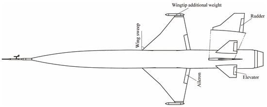
Figure 1.
Plan view of the research LSR aircraft.
On the basis of computational fluid dynamics (CFD) simulations, a high-dimensional linear interpolation table is constructed to create an accurate aerodynamic model. The nonlinear lateral–directional dynamic equations [20] can then be formulated using this model:
Equation (1) is notable for its strong coupling between roll and yaw dynamics, which encompasses various forms of coupling, including aerodynamic coupling, control coupling, motion coupling, and inertial coupling. In the case of an LSR fuselage aircraft, the moment of inertia coupling can become particularly pronounced during rapid roll maneuver flight.

Table 1.
General properties of the research aircraft [21].
Table 1.
General properties of the research aircraft [21].
| Parameter | Explanation | Value |
|---|---|---|
| Reference area | 1.2 m2 | |
| Mean aerodynamic chord | 0.5 m | |
| Wingspan | 2.1 m | |
| Mass | 280 kg | |
| Product of inertia xz | 6 kg·m2 | |
| Moment of inertia around the x-axis | 9 kg·m2 | |
| Moment of inertia around the y-axis | 300 kg·m2 | |
| Moment of inertia around the z-axis | 300 kg·m2 |
Define
From a stability perspective, the influence of the inertial coupling term is dependent on the angular velocity. During a rapid roll maneuver, if an aircraft has upward pitching angular velocity, the term will destabilize the aircraft. Conversely, if the aircraft has downward pitching angular velocity, the term will stabilize it. Therefore, the inertial coupling moment affects both the aircraft’s stability and its dynamic response.
For a wing-level flight with zero sideslip angle and roll angle, by applying the small disturbance theory, the nonlinear model in Equation (1) can be linearized as follows:
The parameters of the moments and forces induced by the sideslip angle, roll angular rate, and yaw angular rate can be defined as
where .
3. Incremental Nonlinear Dynamic Inversion Control Law Design
3.1. INDI Derivation
The nonlinear control–affine dynamic system can be expressed as
where is the state vector, is the control input vector, is the mapping function , and g is the mapping function , whose columns are smooth and nonsingular vector fields [13]. In practice, f is a nonlinear dynamic function related mainly to the state variables, and g is the control distribution function. It is assumed that and the output vector . A first-order Taylor series expansion for the system in Equation (5) in the neighborhood of the point can be expressed as
where
where and are the current state and control variables, respectively. and , indicated by the subscript ‘0’, are the current state matrix and control matrix, respectively; denotes higher-order terms (HOT). Note that the control matrix needs to be inverted. The sampling rate is assumed small enough that the state variable x changes significantly more slowly than the control variable u. Thus, can be assumed to be comparable to the increment of u in one sampling time step. Without considering the higher-order part and the increment of the state, Equation (6) can be simplified as
where , which represents the control increment in one sampling time step . For the inner-loop angular rate control, can be estimated using a virtual angular accelerometer [16], calculated from an onboard model (OBM) with the derivative of the angular rates [22] or measured directly by an angular accelerometer [23]. In addition, the input–output relative control degree of the inner-loop angular rate control is equal to one, which means there are no internal dynamics [24]. The model information in Equation (8) is replaced with sensor measurements; however, in a regular explicit nonlinear dynamic inversion (NDI) controller, the nonlinear feedback term is needed [25]. Thus, the INDI control approach is less sensitive to model mismatch [13] and improves the robustness of NDI to model uncertainties [26]. The virtual control input ν is introduced and replaces in Equation (8), and the increment control output can be calculated as
The control command to the actuator of the INDI controller is equal to the sum of the previous control input and the increment control output, as
The requirements of the INDI controller are composed of the control derivatives , the state derivative , the virtual control input ν, and the control position , as shown in Equations (9) and (10). In addition, Equation (10) can effectively prevent the control jumping problem due to the incremental control form.
3.2. Angular Acceleration Estimation
In terms of angular rate control, the state derivative serves as an estimate of the angular acceleration, encompassing both the inner nonlinear dynamics and outer disturbances encountered by the aircraft. The accuracy of this estimation is critical for achieving optimal control performance.
CF is commonly used in attitude estimation due to its high computational efficiency and simple structure. As depicted in Figure 2, a proportional integral (PI) compensator is used to correct the estimated error, and the state dynamics can be expressed in the Laplace transform domain as follows:
where and are PI compensator gains; corresponds to gyroscope measurements, while denotes the results obtained from the mathematical model calculations. Specially, is equivalent to . Additionally, the variable signifies the estimation result for angular rate, which is equal to . Equation (11) can be rearranged as
where
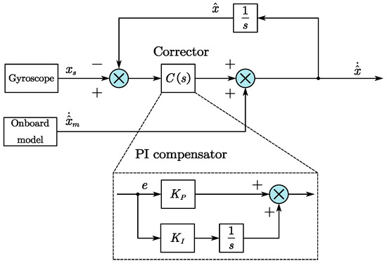
Figure 2.
Block diagram of complementary filter for acceleration estimations [27].
The PI compensator gains can be chosen as and . The transfer function of and are complementary, and their sum equals 1. Figure 3 presents the Bode plot of the transfer function and with a cut-off frequency of and the damping coefficient . A higher value of introduces more measurement information to estimate the angular acceleration, leading to a better response to external disturbances and model uncertainties and a faster response speed [27]. However, it also amplifies the measurement noise. Moreover, the high-pass filter introduces model information to improve the phase margin [28]. The choice of is crucial in CF, as it determines the weighting factor for different input signals. The optimal cut-off frequency can be obtained by analyzing the noise properties of the measurements and the estimation error using power spectral density in the frequency domain [29]. Alternatively, least square estimation in the time domain can be used to minimize the estimation error and avoid manual selection of filter parameters [30]. Moreover, the cut-off frequency value can be adjusted on the basis of different flight conditions to achieve better estimation results [31].
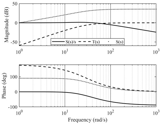
Figure 3.
Bode diagram of the complementary filter transfer functions.
To address the issue of measurement noise not being attenuated in the high-frequency region in the transfer function given by Equation (13) and the resulting interference of noise with the estimated angular acceleration signal, an extended state observer (ESO) [19] can be used to estimate the angular acceleration. By taking the mathematically calculated information as control inputs, the following equation can be obtained as
where ; is the angular acceleration residuals outside the model information; and is the derivative of , which is unknown but bounded. Then, a second-order ESO is designed to estimate the residuals, which can be formulated as
where y is the output of the gyroscope and ; and are the estimation of x and , respectively; and are the observer gains. The error dynamics of the ESO can be calculated as
where and are the estimation error. The error equation can be rewritten as
where
The observer gains are determined using pole placement [19], where the choices of and are made. Here, represents the observer bandwidth. The characteristic polynomial of can be expressed as
Under the assumption that the parameter is bounded, it can be concluded that the ESO achieves bounded-input–bounded-output (BIBO) stability. When the system reaches a steady state, referring to Equation (16), we have
The absolute value of the steady-state error is
Finally, the estimated angular acceleration can be expressed as
Rearranging Equation (22) using Laplace transform, we obtain
where
A comparison between Equations (13) and (24) reveals that they share many similarities in their forms, with the main difference being the location of the part . In the case of the CF, the part is present in the numerator of the angular rate transfer function. However, for ESO, the part is in the numerator of the model information transfer function. By setting the observer bandwidth to and choosing and , the Bode diagrams of the CF and ESO are compared in Figure 4.
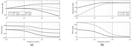
Figure 4.
Bode diagrams of CF- and ESO-based filters: (a) Transfer function S(s) plots and (b) Transfer function T(s) plots.
Figure 4a clearly illustrates that the magnitude of the ESO transfer function decreases beyond the observer bandwidth, while the magnitude of the CF transfer function remains constant. Furthermore, it is observed that exhibits a high degree of high-frequency attenuation with a loop roll-off slope of approximately 20 dB per decade. Consequently, the ESO exhibits superior noise suppression capabilities when compared with the CF. In Figure 4b, both the CF and ESO demonstrate high-pass characteristics for model information, but it is noteworthy that ESO passes more model information in the low-frequency range.
Furthermore, in order to compare the time–domain properties of the two angular acceleration estimators, simplified roll mode dynamics that do not consider the coupling effect are used. The roll mode dynamics can be expressed as
where p is the roll angular rate; is the aileron deflection angle; and and are the roll control parameter and damping parameter, respectively. The roll angular rate is measured by a gyroscope with its noise and bias [32]. The aileron deflection angle is modeled as a sine function and can be expressed as
where is the amplitude and is the input frequency. The on-board model input can be calculated as
where is the gyroscope output with measurement noise.
The selected aileron input has an amplitude of 2 deg and a frequency of 2 Hz, and the estimation results are presented in Figure 5. The estimated angular rates of ESO and CF are nearly identical, and both estimators exhibit excellent filtering performance, as shown in Figure 5a. However, as depicted in Figure 5b, the ESO provides a better estimate of the angular acceleration without introducing any angular rate measurement noise, which is consistent with the frequency domain analysis presented earlier. However, due to its positive gain in the high-frequency range, as depicted in Figure 3, the CF amplifies the sensor noise in the estimation results of angular acceleration. Conversely, the ESO exhibits an attenuated gain for high-frequency noise, as shown in Figure 4a. Therefore, it can be concluded that when accounting for measurement noise, ESO is capable of providing higher-quality angular acceleration estimation information in comparison with CF.
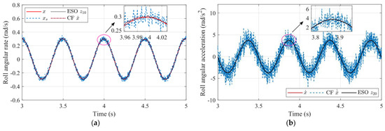
Figure 5.
Time–domain analysis of CF- and ESO-based filters: (a) Angular rate estimation comparison and (b) Angular acceleration estimation comparison.
3.3. Reference Model with Pseudo-Control Hedging
The concept of pseudo-control hedging (PCH) was initially proposed as a means to enhance the performance of adaptive control [33], specifically by modifying the reference model in situations where input position and rate saturation occur. In the presence of actuator saturation, it is possible for the control performance to degrade or even for the controller to become unstable [34]. To address this issue, PCH is introduced. In comparison with the reference governor (RG) [35], which is employed as a control reconfiguration strategy in fault-tolerant control, the PCH method offers the advantage of low computational cost, as it eliminates the need for computing the auxiliary reference (AR) sequence. In the ideal scenario, where the effect of actuator dynamics is not considered and the true values of angular acceleration and angular rate are used, the PCH signal is obtained by subtracting the estimated saturated input from the virtual command output . The command signal is utilized as a feedforward term to improve the tracking performance, as depicted in Figure 6. In order to make the steady-state value of PCH equal to , a control gain is introduced, which can be formulated as
where is the PCH signal used to slow down the dynamics of the reference model when the saturation is triggered, and the gain can be calculated as [36]
where and are gain of the reference model and the error controller, respectively. The inequality holds, because in general control practice, the reference model is designed to have slower dynamics compared with the error controller. This is implemented to prevent the error controller from being overloaded and to ensure a stable closed-loop system.

Figure 6.
Reference model with PCH.
With regard to the roll mode dynamics described in Equation (25), the selected maximum absolute value for the aileron deflection angle is 5 degrees. The reference model and error controller gains are chosen as 8 and 10, respectively.
Figure 7 compares the response of the system states and the virtual control command in the hedged and unhedged simulations. During the first 3 s of the simulation, the results are nearly identical, indicating that the PCH is not activated when the control output is not saturated. However, at 3.5 s, the control effectiveness of the roll mode drops by 95%, resulting in the roll angular rate being unable to maintain the commanded value, as shown in Figure 7a. At the activation of the PCH, depicted in Figure 7b, the virtual control requirements are reduced by slowing down the reference signal. At the 4 s mark, when the command shifts to the opposite direction, the virtual command of the PCH is increased to minimize the tracking error, as illustrated in Figure 7a. When the control output saturates, the PCH is capable of more rapid tracking of the command value.

Figure 7.
Roll mode dynamic simulation results with and without PCH: (a) Roll angular rate comparison and (b) Virtual control commands comparison.
3.4. Synchronization Filter
To ensure the effective operation of the INDI controller [37], it is essential to synchronize the angular acceleration and control surface deflection. Failure to do so may result in unsynchronized delays between the actuator and angular rate estimations, which can cause oscillatory behavior [32] and even lead to control divergence. For further clarification, please refer to Equation (23) and Figure 6.
It is important to take into account the angular rate sensor model, which is denoted by and can be mathematically represented as a first-order lag system with a time constant of . Additionally, it is crucial to consider the dynamics of the actuator. To this end, a second-order linear actuator model is utilized in the synchronization filter, as outlined below:
where and are the estimated natural frequency and damping ratio of the actual actuator used, respectively. Finally, the synchronization filter can be formulated as
It is worth highlighting that the angular acceleration input to the ESO, which is computed using the mathematical model, also needs to be synchronized. To achieve this, Equation (23) can be referenced, and the response delay caused by the physical actuator must be taken into account. To this end, the estimated actuator model is applied to the mathematically calculated results, as shown below:
where is the calculated result.
3.5. Overall Control Structure
3.5.1. Outer-Loop Control
The control structure of the system is divided into two main components: outer-loop control and inner-loop control. Specifically, the lateral acceleration and the bank angle are selected as the outer-loop control variables. To achieve attitude decoupling control, the time–scale separation principle is employed [38]. The control loop is divided into a fast-speed inner angular rate control and a low-speed outer attitude control loop. The output of the outer loop comprises the roll and yaw angular rate control commands.
In order to achieve lateral acceleration control, the closed-loop dynamics of the yaw angular rate control is modeled as a first-order lag system. This can be approximated using the formula , as depicted in Figure 8b. Consequently, the closed-loop dynamics of can be expresssed as
where is the control bandwidth of the yaw control loop. In addition, the damping ratio of the second-order system is selected as 0.8, and the controller gain is calculated as
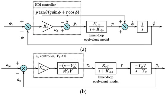
Figure 8.
Outer-loop control structure: (a) Bank angle control loop and (b) Lateral acceleration control loop.
As depicted in Figure 8a, nonlinear dynamic inversion (NDI) control is used for the bank angle control. The virtual control is defined as
where is the control bandwidth of the bank angle. The integrated navigation module, which is commonly installed in aircrafts, provides readily available and accurate information on both the angular rate and attitude. This makes it possible to effectively cancel these factors during NDI design. Therefore, the roll angular rate command can be derived as
3.5.2. Inner-Loop Control
The inner loop is responsible for controlling the roll and yaw angular rates, which are the main control objectives. Building upon the previous research, the overall control structure is depicted in Figure 9. It can be observed that the control structure comprises five key components: the reference model, error controller, angular acceleration estimation, control synchronization, and control allocation. While the aforementioned sections focused on discussing the former four components, the latter (control allocation) will be addressed separately.

Figure 9.
Inner-loop control structure.
In the control allocation module, a hard cross-connection method [7] is employed to effectively decouple the control coupling between the aileron and the rudder. By referencing the control input matrix in Equation (3), it is possible to reformulate the roll–yaw control coupling matrix as follows:
Assuming no control cross-connection between the aileron and rudder, the desired decoupled control matrix for the roll and yaw channel can be expressed as follows:
The pseudo-inverse method is applied to realize control decoupling, and the hard cross-connection matrix can be calculated as
where is the pseudo-inverse of , which can be obtained using the singular value decomposition. Furthermore, it is worth noting that other control allocation methods based on optimization [39] can also be utilized in conjunction with the control structure illustrated in Figure 9. Ultimately, the control output to the actuator can be determined by dividing the control efficiency parameter, as follows:
where .
4. Simulation Verification and Discussion
4.1. Influence of Model Mismatches and Sensor Noises
To assess the control performance of the proposed control structure for supersonic flight, the research aircraft is first trimmed at an altitude of 10,000 m and a speed of 1.5 Mach. The resulting lateral–directional modes of the aircraft at the trimmed point are presented in Table 2. As shown, all modes are stable. However, the Dutch-roll mode exhibits a damping ratio of only approximately 0.06, which is roughly ten times lower than the minimum damping ratio of 0.4 required for level 1, class IV flight vehicles, according to military specifications [40]. Additionally, the frequency of this mode is below the required level of 1 rad/s.

Table 2.
Characteristics of the lateral–directional modes.
The actuator is modeled as a second-order linear system with deflection angle and rate limits, as specified in Table 3. The sampling rate is set to , which corresponds to the operation step of the digital flight control computer.

Table 3.
Characteristics of the control actuators [21].
The parameter in the NDI control was selected as 2 to satisfy the bank angle tracking velocity requirement, and the remaining control parameters are presented in Table 4.

Table 4.
Control parameters.
The gain of the error controller is selected as slightly greater than the reference model gain to ensure that the PCH gain is a positive number. The estimated natural frequency and damping ratio of the actuator are selected to be the same as the actuator model used for simulation. For angular acceleration estimation, the bandwidth of the ESO estimator is chosen to be 30 rad/s, which should establish a tradeoff between noise suppression and estimation accuracy. The number of control parameters that need to be adjusted is quite small, and each of them is connected to the bandwidth principle in the frequency domain, which can be easily chosen under physical restrictions.
It should be noted that the onboard model calculation depicted in Figure 9 is a simplified version designed to decrease the reliance on specific models. This simplified calculation omits the consideration of damping and static aerodynamic coefficients and focuses solely on the control efficiency parameters. This approach is based on Equation (33) and results in the following simplified expression:
To explain it another way, the unaccounted-for dynamics are treated as a component of the overall disturbance that is to be estimated by the ESO. As a result, the ESO is capable of achieving a high degree of accuracy in estimating the disturbance.
Figure 10 displays the results of the nominal simulation for the ESO-based INDI controller. As depicted in Figure 10a, the estimated roll angular acceleration closely tracks the actual value computed by the aircraft model’s dynamic equations. Despite the significant deviation between the simplified onboard model results and the actual value, the ESO’s estimates demonstrate high accuracy. As shown in Figure 10b, the estimated yaw angular acceleration exhibits good steady-state accuracy, although the transients are not as sound as those of the roll channel. Furthermore, the angular acceleration generated by the rudder is even opposite to the actual value because the rudder deflection generates the side force, which produces the angular acceleration. Therefore, it would be preferable to consider the direct force produced by the rudder if the model’s accuracy permits. However, to verify the proposed controller’s performance under a simplified onboard calculation model, this research does not compensate for the direct force component.
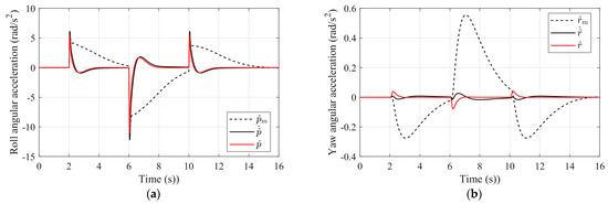
Figure 10.
Angular acceleration estimation: (a) Roll angular acceleration estimation and (b) Yaw angular acceleration estimation.
To compare the performance of the ESO-based and CF-based INDI controllers and investigate the effect of noise on control performance, the same noise as in Section 3.2 is added to the roll and yaw angular rate channels. Additionally, to consider coordinated roll maneuvers, the lateral acceleration command is set to zero, and the bank angle command is set to 30 degrees. The roll angle command is generated using doublet signals with a 4 s interval to simulate a rapid continuous roll maneuver.
To evaluate the disturbance rejection ability, the roll and yaw angular rate channels are disturbed by Gaussian white noise with a standard deviation of 0.01 rad/s. The dashed line in Figure 11 shows the tracking performance of the INDI controller with the CF method under noise disturbance. Compared with the ESO-based INDI controller, the CF-based INDI controller has a larger overshoot in both the roll angle and angular rate response. Meanwhile, the maximum lateral acceleration also increases to 4 m/s2, which exceeds the design requirement. However, the overshoot of the roll angle and angular rate responses of the ESO-based INDI controller is small. In addition, the lateral acceleration and bank angle tracking performance is consistent with the nominal simulation. Therefore, the ESO-based INDI controller exhibits better disturbance rejection ability than the CF-based INDI controller under the same noise level.
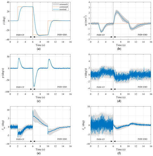
Figure 11.
One thousand simulations with model mismatches and sensor noises: (a) Bank angle response; (b) Lateral acceleration response; (c) Roll angular rate response; (d) Yaw angular rate response; (e) Aileron deflection angle; and (f) Rudder deflection angle.
However, the actuator command output shows significant differences, as seen in Figure 11e,f. When the ESO-based INDI controller is activated, the command oscillations of the aileron and rudder are immediately and significantly reduced. This is attributed to the better noise suppression property of the ESO-based angular acceleration estimator, which reduces the working load of the servo, leading to an improvement in the working life of the servo and a reduction in the working energy consumption.
To further evaluate the control performance of the ESO-based INDI controller under model mismatches, several additional simulations are conducted. The parameters in Table 5 are intentionally varied to simulate different levels of model mismatches.

Table 5.
Model parameters mismatches.
To evaluate the control performance of the ESO-based INDI controller under model mismatches, the parameters of the actuator are perturbed, and the estimated actuator model is used in the control law design. The model parameters are sampled using a uniform distribution, and 1000 Monte Carlo simulations are conducted. The results are summarized in Table 5, and the influence of the model mismatches on the state response and control output is shown in the grey shaded area in Figure 11.
During the 1000 Monte Carlo simulations, the controller exhibits robustness, as it does not oscillate or diverge. This confirms the effectiveness of the ESO-based INDI controller in mitigating the effect of model parameter perturbations. Figure 11a,c show that there is minimal impact on the roll control channel, and the grey shaded areas are almost non-existent. As a result, accurate roll maneuvering can be achieved despite the model mismatches listed in Table 5. The root-mean-square (RMS) error is used to evaluate the tracking performance of the angular rate control loop, which can be computed as follows:
where N is the sampling times; and are the reference value and state response, respectively. Figure 12 illustrates the dispersion of the RMS error for roll and yaw angular rate tracking under various model mismatches. The median values of the RMS error for roll and yaw are approximately 2.5 deg/s and 0.22 deg/s, respectively. The ESO-based INDI controller demonstrates a high-precision tracking performance in the inner angular rate control loop despite the uncertainties in the system model.
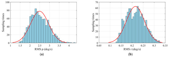
Figure 12.
Dispersion analysis of RMS errors with Gaussian distribution fitting: (a) Roll angular rate tracking error RMS and (b) Yaw angular rate tracking error RMS.
To assess the effectiveness of the proposed control law, the performance is compared with the NDI control law introduced in Reference [41]. The control parameters for the roll and yaw rate channels are selected from Table 4, while the model parameters undergo perturbation within the range specified in Table 5. To evaluate the control performance, a Monte Carlo simulation consisting of 1000 runs is conducted. The RMS of the angular rates tracking error is calculated and is depicted in Figure 13, providing a quantitative measure for comparing the proposed control law with the NDI control law.
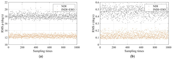
Figure 13.
RMS comparison between NDI and the proposed control law: (a) Roll angular rate tracking error RMS and (b) Yaw angular rate tracking error RMS.
Figure 13 demonstrates that the INDI control law outperforms the NDI control law in regulating both the roll and yaw angular rates under parameter perturbation conditions. Specifically, during supersonic roll maneuvers, the INDI control law reduces the roll angular rate tracking error by 50%. This significant improvement contributes to enhancing the quality of outer-loop roll angle control, leading to improved performance and stability in the control system.
4.2. Sensitivity Analysis
Reference [42] established the proportionality between the time-delay margin and the actuator’s time constant for the INDI controller, as demonstrated by rigorous mathematical proofs. Consequently, the actuator’s natural frequency has a significant impact on the stability and robustness of the INDI-based control algorithm. In the case of lateral–directional control with the ESO-based INDI controller, several parameters are involved, including the model and actuator parameters. Thus, it is essential to clarify the effect of perturbing different parameters on the proposed controller’s robustness. Specifically, the uncertainty parameters, including the control derivative parameters (), the static aerodynamic parameters (), and the damping aerodynamic parameters (), are set to 20%, 30%, and 50% of their nominal values, respectively, as per the linearized model given by Equation (3). The actuator uncertainty is assumed to be the same as that specified in Table 5.
The robust control toolbox in MATLAB [43] is utilized to determine the sensitivity of each uncertainty element through parameter perturbation. Figure 14 displays the percentage contribution of each parameter to the deterioration of robustness, where the sum of the percentage is equal to 1. The larger the percentage of the parameter, the greater the impact on the deterioration of robustness. Notably, the natural frequency of the actuator is identified as the parameter with the greatest impact on robustness, contributing to 60% of the deterioration. This conclusion aligns with the findings in reference [42]. The uncertainty of the control derivative parameters is identified as the second most influential parameter, as has been suggested in the previous literature [32,42]. However, the directional static and damping aerodynamic parameters are found to have little influence on the robustness. Figure 14 also emphasizes the significance of the lateral static and damping aerodynamic parameters for the LSR aircraft during supersonic flight.
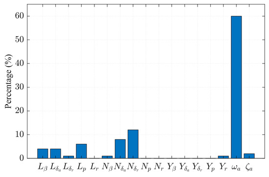
Figure 14.
Different parameters’ percentage contributions to the deterioration of robustness.
4.3. Flying Quality and Stability Margin Evaluation
To investigate the influence of the cut-off frequency on flying quality, the CF-based INDI controller is analyzed using a low-order equivalent system (LOES) based on linear analysis. The evaluation of the lateral closed-loop system, following MIL-STD-1797A specifications [44], includes the equivalent gain n , Dutch-roll damping , Dutch-roll frequency , roll time constant , spiral root , and equivalent time delay .
In Figure 15, it can be observed that the flying quality assessment results are at level 1, indicating satisfactory flight quality. Moreover, as the cut-off frequency increases, the aircraft’s mode frequency also increases. However, as shown in Figure 16, the phase margin first increases and then decreases with an increase in . This indicates that a very large value of should be avoided, as it may lead to a decay in the phase margin, posing a risk to the stability of the controller.
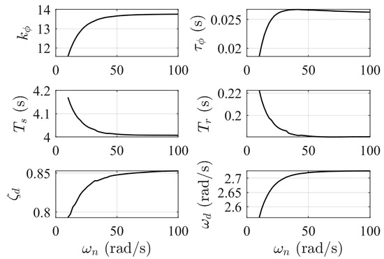
Figure 15.
Results of equivalent system analysis as a variation of the cut-off frequency.
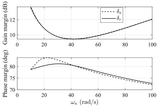
Figure 16.
Variation of gain and phase margins at the breakpoint of the actuators with the cut-off frequency.
Evaluation indicators, such as gain and phase margin, are crucial for practical engineering applications of the ESO-based INDI controller. The Bode diagram breaks at the aileron and rudder input points are presented in Figure 17a,b, respectively. Remarkably, the crossover frequency remains largely unchanged, even in the presence of the parameter uncertainties listed in Table 5. Additionally, the gain curve exhibits a consistent slope around the cross point, indicating the robustness of the controller under parameter perturbations.
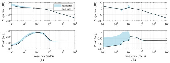
Figure 17.
Bode diagram breaks at the actuators: (a) Aileron and (b) Rudder.
Figure 18 presents the boxplots of the gain and phase margins. The lower and upper edges of the boxes correspond to the 25th and 75th percentiles, respectively. On the basis of the analysis of 1000 samples, it can be observed that the gain margins exceed 6 dB, and the phase margins exceed 45 degrees within the range of 25~75% of the samples. These results indicate that the gain and phase margins of the system meet the required flying qualities of 6 dB and 45 degrees, respectively [45].
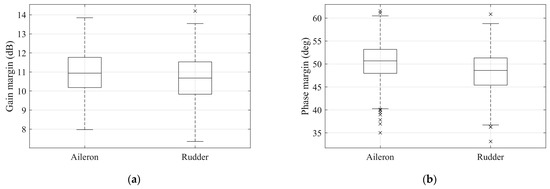
Figure 18.
Gain and phase margins at the actuator: (a) Gain margins and (b) Phase margins.
To further evaluate the impact of time delay in the angular acceleration signal on the stability margin, we add the delay to the feedback of the roll and yaw angular rate signals. The angular acceleration is estimated by ESO with gyroscope measurements. For convenience, we apply a first-order Padé approximation to the delay, which is most accurate at low frequencies [42].
As seen in Figure 19a,b, the phase margin is more sensitive to time delay compared with the gain margin, and it decays more rapidly with an increasing delay. Even with a delay of 25 ms, the gain margin remains greater than 6 dB, while the phase margin drops below 30 degrees. As described in Section 3.4, it is essential to consider the delay in the synchronization filter design. As shown in Figure 19a,b, incorporating the delay approximation into the synchronization filter significantly improves both the gain and phase margins. Even with a 50 ms delay, the gain and phase margins increase by approximately 4 dB and 20 degrees, respectively.
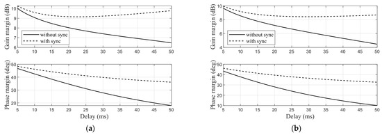
Figure 19.
Variation of stability margins at the breaking points of the actuators with time delay: (a) Aileron and (b) Rudder.
5. Flight Test Validation
Prior to the validation of the control law, a significant amount of hardware-in-the-loop (HIL) simulation is performed, which encompassed the processing of control law switching and the formulation of contingency plans for a spectrum of potential abnormal situations. The actual flight validation is executed after a thorough series of ground tests. The flight control computer operates at a frequency of 200 Hz, with the control parameters for the roll and yaw channels presented in Table 4.
Real-time computation is utilized to allocate control according to the guidelines presented in Section 3.5.2. This involves considering prior aerodynamic data calculations and the aircraft’s current dynamic pressure value. To achieve coordinated flight, it is necessary to set the lateral acceleration command to zero while issuing a roll angle command to correct the aircraft’s lateral deviation from the intended flight path. The aircraft’s lateral maneuver flight, as depicted in Figure 20a,b, is successfully executed within the altitude range of 8000–12,000 m and the Mach range of 0.8–1.25.
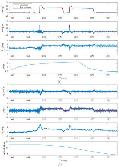
Figure 20.
Flight test results: (a) Roll channel response and (b) Yaw channel response.
During the flight, the roll angle tracking remains normal, displaying remarkable tracking performance characterized by a peak roll angular velocity of 40 deg/s. Additionally, the maximum absolute value of the lateral acceleration does not exceed 1 m/s2 throughout the entire flight, indicating a decoupled control for roll and yaw. Table 6 shows the root mean square (RMS) of the tracking error.

Table 6.
RMS of the tracking error for the flight test.
The inner-loop rate controller is effective in tracking the roll and yaw rate, demonstrating stable performance with negligible variations in steady-state oscillation amplitude across a range of speed and altitude changes. However, it is worth mentioning that a low-frequency limit cycle oscillation exists in the steady-state, which is caused by the impact of the actuators’ backlash.
6. Conclusions
In conclusion, the lateral–directional control of a LSR aircraft presents a significant challenge to flying safety, particularly during the supersonic phase when the aircraft’s flying qualities are relatively poor. As military mission requirements emphasize maneuverability in the supersonic phase, it becomes increasingly crucial to address this challenge. Compared with longitudinal maneuverability, decoupling the lateral and directional dynamics for rapid roll maneuvers adds complexity to the control design.
This study proposes the integration of the ESO algorithm into the INDI control design. By leveraging the ESO’s capabilities, such as suppressing noise in the angular rate sensor and providing better-quality angular acceleration estimates, the proposed control method outperforms the CF method. It effectively reduces command oscillations and improves the servo’s working life. Numerous time-domain simulations are conducted to validate the effectiveness and robustness of the proposed control approach. Additionally, the proposed control undergoes evaluation using frequency-domain metrics for engineering practice, and it successfully meets the required criteria. The sensitivity analysis of parameter uncertainties highlights the importance of considering lateral static and damping aerodynamic parameters, in addition to actuator properties and control derivatives, for successful control design of LSR supersonic aircraft.
Overall, this research contributes to addressing the challenges in lateral–directional control for LSR, providing an effective and robust control approach that achieves high-precision tracking performance during rapid roll maneuvers. The findings of this study have practical implications for the design and implementation of control systems in supersonic aircraft applications.
7. Future Works
The sensitivity of the uncertainties of the parameters is evaluated using a linearized model; in the future, we would like to expand the model using nonlinear dynamics with the rate limit and backlash of the actuator.
Author Contributions
Conceptualization, H.L., Y.C. and T.Z.; methodology, H.L., B.Q., Z.Y. and Y.C.; software, H.L., Z.Y. and Z.G.; validation, H.L., Y.C. and Z.G.; formal analysis, H.L., B.Q., K.C. and Y.C.; investigation, H.L., B.Q. and X.L.; resources, H.L., T.Z. and Z.G.; data curation, Y.C.; writing—original draft preparation, H.L. and Y.C.; writing—review and editing, H.L., Z.Y., Y.C., K.C. and X.L.; visualization, H.L.; supervision, Y.C. and Z.G. All authors have read and agreed to the published version of the manuscript.
Funding
This work was supported by the National Defense Science and Technology Foundation Strengthening Program and the Priority Academic Program Development of Jiangsu Higher Education Institutions (PAPD).
Institutional Review Board Statement
Ethical review and approval were waived for this study due to the reason that the study not in-volving humans or animals.
Informed Consent Statement
Informed consent was obtained from all subjects involved in the study.
Data Availability Statement
The data used to support the findings of this study are available from the corresponding author upon reasonable request.
Acknowledgments
The authors would like to deliver their sincere thanks to the editors and anonymous reviewers.
Conflicts of Interest
The authors declare that there are no conflict of interest regarding the publication of this paper.
Nomenclature
The following nomenclature is used in this manuscript:
| Y | side force (N) |
| L | roll aerodynamic moments (N∙m) |
| M | pitch aerodynamic moments (N∙m) |
| N | yaw aerodynamic moments (N∙m) |
| ϕ | roll Euler angle (rad) |
| θ | pitch Euler angle (rad) |
| V | true airspeed (m/s) |
| p | roll angular rate (rad/s) |
| q | pitch angular rate (rad/s) |
| r | yaw angular rate (rad/s) |
| α | angle-of-attack (rad) |
| β | sideslip angle (rad) |
| deflection angle of the aileron (rad) | |
| deflection angle of the rudder (rad) | |
| commanded deflection angle of the aileron (rad) | |
| commanded deflection angle of the rudder (rad) |
Abbreviations
The following abbreviations are used in this manuscript:
| INDI | incremental nonlinear dynamic inversion |
| LSR | large-slenderness-ratio |
| ESO | extended state observer |
| CF | complementary filter |
| MC | Monte Carlo |
| NDI | nonlinear dynamic inversion |
| CFD | computational fluid dynamics |
| HOT | higher-order terms |
| RMS | root-mean-square |
| LOES | low-order equivalent system |
| HIL | hardware-in-the-loop |
References
- Wang, D.; Wang, J.-F.; Li, L.-F.; Yang, T.-P.; Chen, J.-T. Novel Volume-Improved Design Method of Large-Slenderness-Ratio Cone-Derived Waveriders. AIAA J. 2020, 58, 4832–4847. [Google Scholar] [CrossRef]
- Day, R.E. Coupling Dynamics in Aircraft: A Historical Perspective; NASA: Kern, CA, USA, 1997. [Google Scholar]
- Dydek, Z.T.; Annaswamy, A.M.; Lavretsky, E. Adaptive Control and the NASA X-15-3 Flight Revisited. IEEE Control Syst. 2010, 30, 32–48. [Google Scholar] [CrossRef]
- Orr, J.S.; Dennehy, C.J. Analysis of the X-15 Flight 3-65-97 Divergent Limit-Cycle Oscillation. J. Aircr. 2017, 54, 135–148. [Google Scholar] [CrossRef]
- Sobel, K.; Shapiro, E. Eigenstructure Assignment for Design of Multimode Flight Control Systems. IEEE Control Syst. Mag. 1985, 5, 9–15. [Google Scholar] [CrossRef]
- Ogunwa, T.; Abdullah, E.; Chahl, J. Modeling and Control of an Articulated Multibody Aircraft. Appl. Sci. 2022, 12, 1162. [Google Scholar] [CrossRef]
- Wang, L.; Zhang, N.; Yue, T.; Liu, H.; Zhu, J.; Jia, X. Three-Axis Coupled Flight Control Law Design for Flying Wing Aircraft Using Eigenstructure Assignment Method. Chin. J. Aeronaut. 2020, 33, 2510–2526. [Google Scholar] [CrossRef]
- Nieto-Wire, C.; Sobel, K. Eigenstructure Assignment for a Tailless Aircraft. In Proceedings of the AIAA Guidance, Navigation and Control Conference and Exhibit, Honolulu, HI, USA, 20–23 August 2007; American Institute of Aeronautics and Astronautics: Reston VA, USA, 2007. [Google Scholar]
- Snell, A. Decoupling Control Design with Applications to Flight. J. Guid. Control Dyn. 1998, 21, 647–655. [Google Scholar] [CrossRef]
- Acquatella, P.; Falkena, W.; van Kampen, E.-J.; Chu, Q.P. Robust Nonlinear Spacecraft Attitude Control Using Incremental Nonlinear Dynamic Inversion. In Proceedings of the AIAA Guidance, Navigation, and Control Conference, Minneapolis, MN, USA, 13–16 August 2012; p. 4623. [Google Scholar]
- Lungu, R.; Lungu, M. Automatic Control of Aircraft in Lateral-Directional Plane During Landing: Automatic Control of Aircraft in Lateral-Directional Plane During Landing. Asian J. Control 2016, 18, 433–446. [Google Scholar] [CrossRef]
- Sieberling, S.; Chu, Q.P.; Mulder, J.A. Robust Flight Control Using Incremental Nonlinear Dynamic Inversion and Angular Acceleration Prediction. J. Guid. Control Dyn. 2010, 33, 1732–1742. [Google Scholar] [CrossRef]
- Wang, X.; van Kampen, E.-J.; Chu, Q.; Lu, P. Incremental Sliding-Mode Fault-Tolerant Flight Control. J. Guid. Control Dyn. 2019, 42, 244–259. [Google Scholar] [CrossRef]
- Ahmadi, K.; Asadi, D.; Nabavi-Chashmi, S.-Y.; Tutsoy, O. Modified Adaptive Discrete-Time Incremental Nonlinear Dynamic Inversion Control for Quad-Rotors in the Presence of Motor Faults. Mech. Syst. Signal Process. 2023, 188, 109989. [Google Scholar] [CrossRef]
- Jiali, Y.; Jihong, Z. An Angular Acceleration Estimation Method Based on the Complementary Filter Theory. In Proceedings of the 2016 IEEE International Instrumentation and Measurement Technology Conference Proceedings, Taipei, Taiwan, 23–26 May 2016; IEEE: Piscataway, NJ, USA, 2016; pp. 1–6. [Google Scholar]
- Ren, Z.; Fu, W.; Li, Y.; Yan, B.; Zhu, S.; Yan, J. Enhanced attitude control of unmanned aerial vehicles based on virtual angular accelerometer. J. IEEE Access 2019, 7, 104330–104343. [Google Scholar] [CrossRef]
- Liu, Z.; Zhang, Y.; Liang, J.; Chen, H. Application of the Improved Incremental Nonlinear Dynamic Inversion in Fixed-Wing UAV Flight Tests. J. Aerosp. Eng. 2022, 35, 04022091. [Google Scholar] [CrossRef]
- Valasek, J.; Chen, W. Observer/Kalman Filter Identification for Online System Identification of Aircraft. J. Guid. Control Dyn. 2003, 26, 347–353. [Google Scholar] [CrossRef]
- Gao, Z. Scaling and Bandwidth-Parameterization Based Controller Tuning. In Proceedings of the 2003 American Control Conference, Denver, CO, USA, 4–6 June 2003; Volume 6, pp. 4989–4996. [Google Scholar]
- Chen, J.; Du, N.; Han, Y. Decoupling Attitude Control of a Hypersonic Glide Vehicle Based on a Nonlinear Extended State Observer. Int. J. Aerosp. Eng. 2020, 2020, 4905698. [Google Scholar] [CrossRef]
- Lyu, H.; Gong, Z.; Chen, Y.; Chen, W.; Wang, W. Large-Slenderness-Ratio Supersonic Aircraft Lateral–Directional Coupling Dynamics Analysis and Control. Int. J. Aerosp. Eng. 2022, 2022, 2490675. [Google Scholar] [CrossRef]
- Kim, C.-S.; Ji, C.-H.; Koh, G.-O.; Kim, B.S. Stability Margin and Structural Coupling Analysis of a Hybrid INDI Control for the Fighter Aircraft. Int. J. Aeronaut. Space Sci. 2021, 22, 1154–1169. [Google Scholar] [CrossRef]
- Cakiroglu, C.; Van Kampen, E.-J.; Chu, Q.P. Robust Incremental Nonlinear Dynamic Inversion Control Using Angular Accelerometer Feedback. In Proceedings of the 2018 AIAA Guidance, Navigation, and Control Conference, Kissimmee, FL, USA, 8–12 January 2018; American Institute of Aeronautics and Astronautics: Reston, VA, USA, 2018. [Google Scholar]
- Wang, X.; van Kampen, E.-J.; Chu, Q.; Lu, P. Stability Analysis for Incremental Nonlinear Dynamic Inversion Control. J. Guid. Control Dyn. 2019, 42, 1116–1129. [Google Scholar] [CrossRef]
- Pavel, M.D.; Shanthakumaran, P.; Chu, Q.; Stroosma, O.; Wolfe, M.; Cazemier, H. Incremental Nonlinear Dynamic Inversion for the Apache AH-64 Helicopter Control. J. Am. Helicopter Soc. 2020, 65, 1–16. [Google Scholar] [CrossRef]
- Liu, J. Finite Time Observer Based Incremental Nonlinear Fault-Tolerant Flight Control. Aerosp. Sci. Technol. 2020, 11, 105986. [Google Scholar] [CrossRef]
- Kumtepe, Y.; Pollack, T.; Van Kampen, E.-J. Flight Control Law Design Using Hybrid Incremental Nonlinear Dynamic Inversion. In Proceedings of the AIAA SCITECH 2022 Forum, San Diego, CA, USA, 3–7 January 2022; American Institute of Aeronautics and Astronautics: Reston, VA, USA, 2022. [Google Scholar]
- Ji, C.; Kim, C.; Kim, B.-S. A Hybrid Incremental Nonlinear Dynamic Inversion Control for Improving Flying Qualities of Asymmetric Store Configuration Aircraft. Aerospace 2021, 8, 126. [Google Scholar] [CrossRef]
- Zhao, Y.; Yan, G.; Qin, Y.; Fu, Q. Information Fusion Based on Complementary Filter for SINS/CNS/GPS Integrated Navigation System of Aerospace Plane. Sensors 2020, 20, 7193. [Google Scholar] [CrossRef] [PubMed]
- Narkhede, P.; Joseph Raj, A.N.; Kumar, V.; Karar, V.; Poddar, S. Least Square Estimation-Based Adaptive Complimentary Filter for Attitude Estimation. Trans. Inst. Meas. Control 2019, 41, 235–245. [Google Scholar] [CrossRef]
- Yoo, T.S.; Hong, S.K.; Yoon, H.M.; Park, S. Gain-Scheduled Complementary Filter Design for a MEMS Based Attitude and Heading Reference System. Sensors 2011, 11, 3816–3830. [Google Scholar] [CrossRef]
- van’t Veld, R.; Van Kampen, E.-J.; Chu, Q.P. Stability and Robustness Analysis and Improvements for Incremental Nonlinear Dynamic Inversion Control. In Proceedings of the 2018 AIAA Guidance, Navigation, and Control Conference, Kissimmee, FL, USA, 8–12 January 2018; American Institute of Aeronautics and Astronautics: Reston, VA, USA, 2018. [Google Scholar]
- Johnson, E.N.; Calise, A.J. Pseudo-Control Hedging: A New Method for Adaptive Control. In Proceedings of the Advances in Navigation Guidance and Control Technology Workshop, Huntsville, AL, USA, 1–2 November 2000. [Google Scholar]
- Li, Y.; Liu, X.; Lu, P.; He, Q.; Ming, R.; Zhang, W. Angular Acceleration Estimation-Based Incremental Nonlinear Dynamic Inversion for Robust Flight Control. Control Eng. Pract. 2021, 117, 104938. [Google Scholar] [CrossRef]
- Hosseinzadeh, M.; Kolmanovsky, I.; Baruah, S.; Sinopoli, B. Reference Governor-Based Fault-Tolerant Constrained Control. Automatica 2022, 136, 110089. [Google Scholar] [CrossRef]
- Zhang, J.; Holzapfel, F. Saturation Protection with Pseudo Control Hedging: A Control Allocation Perspective. In Proceedings of the AIAA Scitech 2021 Forumm, Virtual, 11–15/19–21 January 2021; American Institute of Aeronautics and Astronautics: Reston, VA, USA, 2021. [Google Scholar]
- Smit, B.; Pollack, T.; Van Kampen, E.-J. Adaptive Incremental Nonlinear Dynamic Inversion Flight Control for Consistent Handling Qualities. In Proceedings of the AIAA SCITECH 2022 Forum, San Diego, CA, USA, 3–7 January 2022; American Institute of Aeronautics and Astronautics: Reston, VA, USA, 2022. [Google Scholar]
- Saksena, V.R.; O’reilly, J.; Kokotovic, P.V. Singular Perturbations and Time-Scale Methods in Control Theory: Survey 1976–1983. Automatica 1984, 20, 273–293. [Google Scholar] [CrossRef]
- Bodson, M. Evaluation of Optimization Methods for Control Allocation. J. Guid. Control Dyn. 2002, 25, 703–711. [Google Scholar] [CrossRef]
- Nieto-Wire, C.; Sobel, K. Flight Control Design for a Tailless Aircraft Using Eigenstructure Assignment. Int. J. Aerosp. Eng. 2011, 2011, 549131. [Google Scholar] [CrossRef]
- Miller, C. Nonlinear Dynamic Inversion Baseline Control Law: Architecture and Performance Predictions. In Proceedings of the AIAA Guidance, Navigation, and Control Conference, Portland, OR, USA, 8–11 August 2011; American Institute of Aeronautics and Astronautics: Reston, VA, USA, 2011. [Google Scholar]
- Huang, Y.; Zhang, Y.; Pool, D.M.; Stroosma, O.; Chu, Q. Time-Delay Margin and Robustness of Incremental Nonlinear Dynamic Inversion Control. J. Guid. Control Dyn. 2022, 45, 394–404. [Google Scholar] [CrossRef]
- Magni, J.-F. Robust Modal Control with a Toolbox for Use with Matlab®; Springer Science & Business Media: Berlin, Germany, 2012. [Google Scholar]
- Department of Defense. MIL-HDBK-1797 Department of Defense Handbook Flying Qualities of Piloted Aircraft; Department of Defense: Washington, DC, USA, 1997.
- United States Military. Military Specification. In Flying Qualities of Piloted Airplanes; Defense Technical Information Center: Fort Belvoir, VA, USA, 1980. [Google Scholar]
Disclaimer/Publisher’s Note: The statements, opinions and data contained in all publications are solely those of the individual author(s) and contributor(s) and not of MDPI and/or the editor(s). MDPI and/or the editor(s) disclaim responsibility for any injury to people or property resulting from any ideas, methods, instructions or products referred to in the content. |
© 2023 by the authors. Licensee MDPI, Basel, Switzerland. This article is an open access article distributed under the terms and conditions of the Creative Commons Attribution (CC BY) license (https://creativecommons.org/licenses/by/4.0/).