Article

Optimized Design of Flexible Quick-Change System Based on Genetic Algorithm and Monte Carlo Method

1
School of Mechanical Engineering, North University of China, Taiyuan 030051, China
2
School of Mechanical Engineering and Automation, Beihang University, Beijing 100191, China
3
Shanxi Aerospace Qinghua Equipment Co., Ltd., Changzhi 046011, China
*
Author to whom correspondence should be addressed.
These authors contributed equally to this work.
Appl. Sci. 2023, 13(11), 6482; https://doi.org/10.3390/app13116482
Submission received: 23 March 2023 / Revised: 15 May 2023 / Accepted: 23 May 2023 / Published: 25 May 2023

Abstract

:
In order to realize the high efficiency and precision clamping of large workpieces with several processes and multiple species processing, the distribution number and position of the zero point clamping unit in the flexible quick-change process system for big thin-walled cylindrical structural parts are presented. The error model of the flexible quick-change process system is established by the Monte Carlo method, which is used to optimize the system structure design. The error variation of the flexible quick-change process system under the action of transposition and extreme working conditions such as cutting force is revealed, and further analysis on the sensitivity of the workpiece’s global displacement error and global attitude error to each error source is carried out. After the optimization, a high-quality, cost-effective, flexible quick-change clamping system is created. The three-coordinate measurement experiment is used to test the functionality and accuracy of the flexible quick-change process system. A significantly improved level of the system’s repetitive positioning accuracy (less than 0.01 mm) is detected. Importantly, the flexible quick-change system obtained by the combinatorial optimal design method has been successfully applied to the production of aerospace components with improved quality and efficiency.

1. Introduction

The aerospace field is progressively exhibiting the trend of high technology, intelligence, and integration as a result of the aerospace industry’s rapid development, which has increased the technological level and production capacity requirements for the aerospace manufacturing sector [1]. More and more thin-walled complex structural parts are used in the structure of aerospace products in order to meet the demanding requirements of aircraft, spacecraft, and precision instruments on the performance and reliability of parts, and the precision requirements for such thin-walled structural parts are also rising [2]. Massive thin-walled structural components are increasingly used in the aerospace industry because they may effectively reduce the number of parts, drastically lower production costs, and well meet the objectives of overall structural lightweight design [3,4]. The requirements for multi-species and multi-process precision manufacturing necessitate numerous iterations of testing, alignment, positioning, machining, repairs, and reworks. This creates a multitude of challenges, including difficult product replacement, inefficient use of resources, high costs, and acting as a bottleneck that prevents product renewal while limiting quality and efficacy. Hence, the efficient production of massive thin-walled parts in the aerospace industry depends greatly on the precise, quick, and economical flexibility of the clamping system [4].
The zero point clamping unit can create a consistent interface between the station, the machine tool, and the process. It also efficiently combines stable clamping with high-precision positioning to guarantee productivity. With its great performance of positioning and locking in one step, decreasing downtime by external clamping, high degree of automation, and high precision, it is extensively utilized in flexible quick-change systems [5]. The current research focus is on how to choose the best number and distribution of zero point clamping systems (geometric structure, angle), as well as how to increase repetitive positioning accuracy, in order to meet the needs of multi-process manufacturing for a variety of workpieces while also achieving the requirements of economy, adaptability, and reliability [6,7].
In the literature, the layout problem of a fixture system is primarily solved using evolutionary algorithms, ant colony algorithms (ACA), genetic algorithms, and so on. Abolfazl et al. [8] used a genetic algorithm and finite element method to optimize the optimal fixture layout of flexible sheet metal components, which improved the geometric quality of the components. Wu [9,10] both adopted a hybrid model of a genetic algorithm and a finite element to extract the optimal positions of clamping points in the fixture, respectively. Du et al. [11] used the simulated annealing algorithm (SAA) as a global optimization method to propose an optimal design method for fixture layout in the assembly process. Vinosh et al. [12] combined evolutionary algorithms and FEM to optimize the design of the fixture. Ramesh et al. [13] proposed the optimization of fixture layout by minimizing the maximum workpiece deformation on a two-dimensional fixture workpiece system in an end milling operation based on hybrid artificial neural network-particle swarm optimization and evolutionary techniques. Qazani et al. [14] achieved higher accuracy by modeling the fixture-workpiece system to position the positioner and fixture. Yu et al. [15] optimized the position of the positioner by generating a response surface model of the assembly model to predict changes in the assembly. Dosdoğru et al. [16] integrated genetic algorithms and Monte Carlo methods to optimize the scheduling problem of flexible job shops from various aspects. Munavalli et al. [17] used genetic algorithms to optimize the design of the layout of the outpatient clinic. Liu et al. [18] proposed a genetic algorithm-based automatic search method for the initial structure of a double liquid lens zoom optical system. In terms of fixture error analysis, Zhao et al. [19] adopted a high-precision end gear plate to achieve high repetitive positioning accuracy and studied a new type of positioner fixture with high repetitive positioning accuracy and high rigidity. Liu Yaxiong [20] carried out an overall error analysis of the process for the zero point clamping system but did not point out the magnitude of the zero point clamping system error relative to other errors. Guo et al. [21] proposed an error compensation method based on a two-stage strategy of a pre-compensation stage and an exact compensation stage in order to achieve precise positioning. Butt et al. [22] utilized a genetic algorithm to optimize positioner placement, allowing for the minimization of part positioning errors during machining operations. Yang et al. [23] developed a comprehensive equivalent fixture error model that can compensate for datum errors, machine path errors, and workpiece deformation during machining through general fixture layouts. Peng et al. [24] constructed a comprehensive position prediction model that can be used to predict the position error of large, thin-walled box-shaped workpieces in a fixture type.
Less research has been performed on the combination of numerous zero point positioning systems for large structural sections; the majority of earlier studies have focused on the best design of individual zero point positioning systems. The article studies the layout of zero point positioning units, the dimensional tolerances of foundation plates and fixture plates, frequent lifting and changing positions, and gravity, which are the main factors affecting repetitive positioning accuracy, in order to design a high-quality flexible quick-change process system. The goal of this study is to create a high-precision, flexible quick-change system for many species of large, thin-walled parts that can achieve the interchanging and connecting of numerous processing flows with just one clamp.

2. Material and Methods

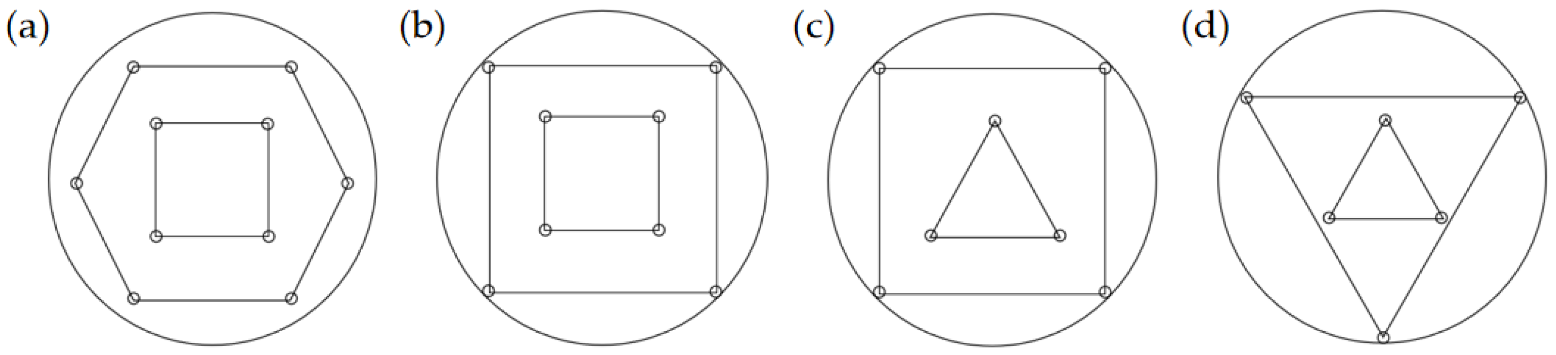
2.1. Layout Structure Design Optimization of a Flexible Quick-Change Process System

Finding the ideal quantity, placement, and direction of zero point clamping units for each component in the assembly is the goal of layout optimization for flexible quick-change systems. In order to reach higher quality standards, accuracy must be the primary goal while also meeting the processing needs of many processes and multiple varieties. The layout of the zero point clamping unit will help reduce the impact of fixture system deformation. The forces on thin-walled cylindrical structural parts during turning and milling were examined in order to ensure that the flexible quick-change process system could be used with workpieces subject to various machining techniques. The maximum cutting force of 4200 N under extreme working conditions was chosen as the mechanical design basis for the flexible quick-change process system.
In order to make all the workpieces applicable to the unified production line, as depicted in Figure 1, four kinds of initial layout are designed first for the distribution of zero point clamping units in the flexible quick-change process system, considering the geometric size range of the series of workpieces (from 280 mm to 1200 mm) and its structural characteristics.
On the basis of determining the preliminary lattice layout structure (4 positioning pins on the outer ring and 3 positioning pins on the inner ring) according to mechanical characteristics analysis, the layout position of the zero point positioning unit is optimized using a genetic algorithm. Based on the experimental positioning accuracy results of two zero point positioning units with 400 mm spacing (repetitive positioning accuracy of 9 μm), a multi-objective constrained optimization model for positioning and clamping layout optimization is established. The layout positions of each zero point clamping unit in the polar coordinate system are shown in Figure 2.
Set the overall layout of the system to be symmetrical to reduce uneven deformation. The position of the positioning pins in the system layout is taken as the design variable, the minimum sum of the spacing between the positioning pins is taken as the objective function, and the maximum number of the distance between the internal points and the external points is ensured to be less than 400 mm. The mathematical model of layout optimization can be expressed as:
F i n d :   x = x 1 , x 2 , x n                         r = r 1 , r 2 , r n min S = i = A C j = D G S i j
where x and i represent the position coordinates of the outer ring positioning pins in the polar coordinate system, and n represents the number of positioning pins. S represents the sum of the spacing between positioning pins (A to C and D to G represent the inner and outer ring positioning pins of the flexible quick-change system, respectively).
In the polar coordinate system, the coordinates of each point are: A: 250 3 3 , x ; B: 250 3 3 , x + 2 3 π ; C: 250 3 3 , x + 4 3 π ; D: 400 2 , π 4 ; E: 400 2 , 3 π 4 ; F: 400 2 , 5 π 4 ; and G: 400 2 , 7 π 4 .
The formula for the distance between two points in the polar coordinate system is:
S = r 1 2 2 r 1 r 2 cos θ 1 θ 2 + r 2 2 .
The sum of the distances between the points:
y = AD + AE + AF + AG + BD + BE + BF + BG + CD + CE + CF + CG = a bcos x π 4 + a bcos x 3 π 4 + a bcos x 5 π 4 + a bcos x 7 4 + a bcos x + 5 π 12 + a bcos x π 12 + a bcos x 7 π 12 + a bcos x 13 π 12 + a bcos x + 13 π 12 + a bcos x + 7 π 12 + a bcos x + π 12 + a bcos x 5 π 12 ,
of which:
a = r 1 2 + r 2 2 = 250 3 3 2 + r 2 = r 2 + 20833.33 ,
b = 2 r 1 r 2 = 2 × 250 3 3 × r = 288.675   r ,
x 0 ,   2 π 3 ,   r 537.67 , 565.6854 .
In addition, the following conditions should be met:
a bcos x 7 π 12 400 ,
a bcos x 5 π 12 400 .

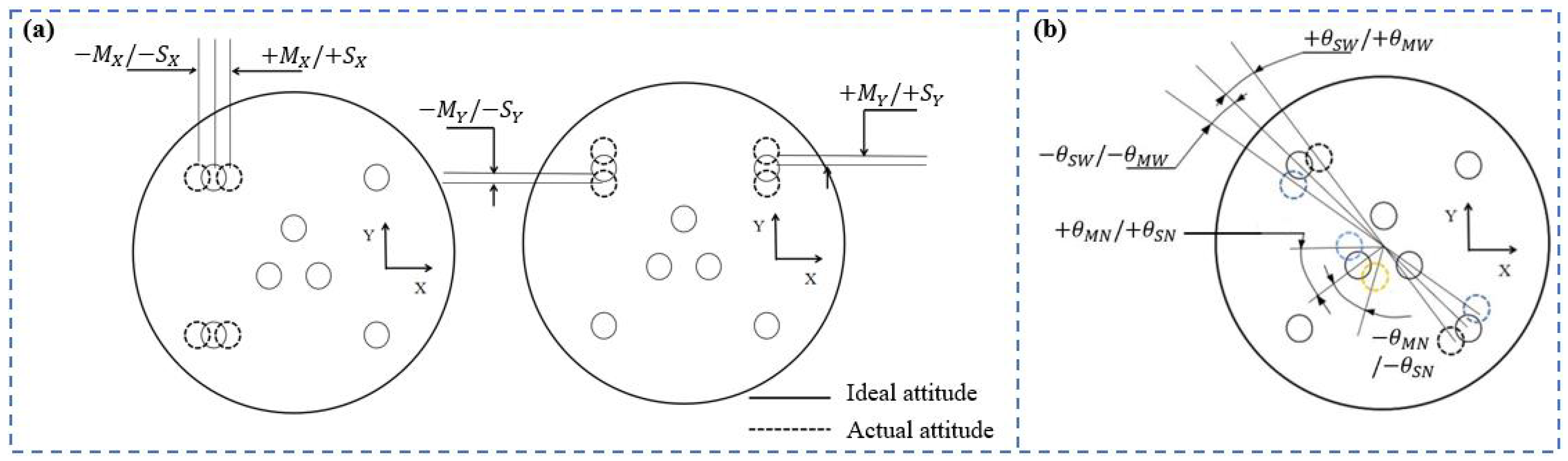
2.2. Error Model and Optimization of a Flexible Quick-Change Process System Based on the Monte Carlo Method

As illustrated in Figure 3, the workpiece pose error generated by static and non-static positioning variation for the flexible quick-change process system-workpiece may create a thorough correlation structure between the fixture error sources and the workpiece pose deviation. According to the figure, the error sources are as follows: dimensional deviation of the fixture plate and foundation plate; flatness error; positioning pin mounting hole position error; zero point clamping unit mounting hole position error; positioning error caused by zero point clamping unit manufacturing accuracy; fit tolerance of the zero point clamping unit with the foundation plate; and gap error caused by frequent disassembly. Among these, the gap error in a short period of time and the fit tolerance of the zero point clamping device after installation are both negligible and can be disregarded.
The assembly errors of the flexible quick-change process system come from the zero point clamping unit, the fixture plate, and the foundation plate, respectively. The error model of the flexible quick-change process system can be created by adding the two algebras after analyzing the error generated by the zero point clamping unit and other components independently.

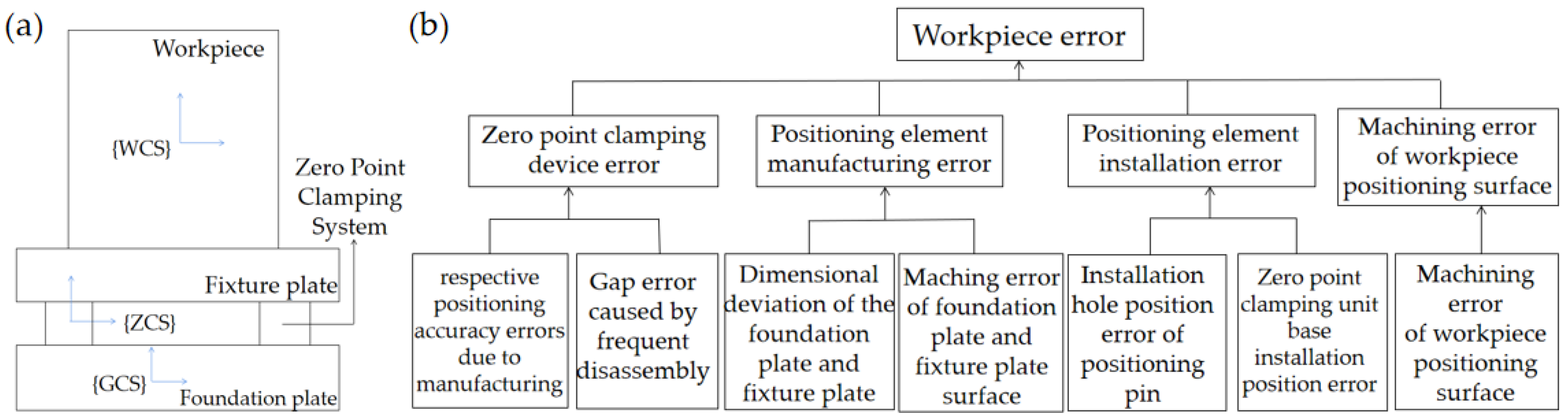
2.2.1. Zero Point Clamping Unit Error Model

The zero point clamping unit in the flexible quick-change process system uses a SCHUNK supplier’s NSE3-138 type with a repetitive positioning accuracy of 0.005 mm for a single zero point clamping unit. Figure 4 depicts the posture deviation error model of the flexible quick-change process system brought on by the zero point clamping unit’s manufacturing precision. When the repetitive positioning error of the zero point clamping unit is δ, the errors in the X, Y, and Z directions are δcosα, δsinα, and δ/2, respectively. The workpiece’s rotation angle deviation around the X and Y axes will be affected by the error in the Z direction and will be approximately equal to L, where L is the distance between the zero point clamping pin and the one-way positioning pin.
Assume that the positioning pin on the fixture plate and the positioning hole in the base of the zero point clamping unit on the foundation plate of the flexible quick-change process system are out of alignment in both position and posture. The position deviation caused by the zero point clamping unit is then represented by the flexible quick-change process system using the following model [20].
q w 0 = Δ R w 0 , Δ θ w 0 T = δ cos α , δ sin α , δ / 2 , tan θ , tan θ , 0 T
where q w 0 , Δ R w 0 , and Δ θ w 0 are the total error, total position deviation, and total attitude deviation caused by the zero point clamping unit, respectively. Additionally, δ refers to the repetitive positioning accuracy of the zero point clamping unit; α indicates the angle with the X-axis; and θ indicates the angle deviation of the workpieces around the X- and Y-axes.

2.2.2. Error Model Caused by Components except the Zero Point Clamping Unit

In addition to the zero point clamping unit, only the fixture plate and the foundation plate remain in the flexible quick-change process system, whose position error and posture error are shown schematically in Figure 5. Two adjacent mounting holes for the zero point clamping unit and mounting holes for positioning pins are spaced apart by 0.015 mm on the outer rings of the foundation plate and the fixture plate, respectively. The foundation plate and fixture plate have a surface flatness tolerance of 0.015 mm. When both position tolerances exist as ±M and ±S, the error ΔM will result in the existence of errors on the X- and Y-axes of ±MX and ±MY for the fixture plate, whereas ΔS will cause the errors between the positioning pins on the X- and Y-axes to exist as ±SX and ±SY.
As the positioning pin mounting holes on the outer ring of the foundation plate and fixture plate, as well as the two neighboring zero point clamping units, are all shifted in the same direction, the remaining mounting holes are shifted in the opposite direction. The rotational angle errors θ MW = Δ M / L w and θ SW = Δ S / L w around the Z-axis will occur. In the meantime, the three holes of the inner circle of the foundation plate and the fixture plate rotate along the circumference at the same time. The errors of its rotation angle around the Z-axis are θ MN = Δ M / L N and θ SN = Δ S / L N , because LN > LW, LW > LN, then θMW > θMN and θSW < θSN, which also indicates that the maximum value of rotational error can only be θMW and θSN.
Suppose there are Δ R w R 3 × 1 and Δ θ w R 3 × 1 deviations in the workpiece position and attitude on the flexible quick-change process system. Then the posture deviation of the workpiece is q w = Δ R w , Δ θ w T . Consequently, the error formula of the flexible quick-change process system can be obtained by adding the error model of the zero location element with the error module algebra caused by the foundation plate and fixture plate.
q w = Δ R w , Δ θ w T = δ + M + S cos α ,   δ + M + S sin α ,   δ 2 + P M + P Z ,   δ L w ,   δ L w ,   ± M L w + ± S L w T
where q w , Δ R w , and Δ θ w indicate the overall error of the flexible quick-change process system workpiece, position error, and attitude error; M indicates the position tolerance of two adjacent positioning pin mounting holes on the outer ring of the fixture plate; S indicates the flatness tolerance of the surface of the base plate and fixture plate; P M and P Z indicate the Z-directional error brought about by the flatness tolerance of the surface of the base plate and fixture plate; and L w indicates half of the distance between the zero point positioning pin and the one-way positioning pin of the outer ring of the fixture plate.

3. Results and Discussion

3.1. Mechanical Properties of the Different Zero Point Positioning Unit Layouts

The mechanical analysis of the flexible quick-change system is carried out with the extreme working load (the maximum cutting force in the process) at the highest point of the maximum workpiece. With the difference in number and position of the zero point clamping units, the mechanical distribution of the system is shown in Figure 6.
We can see that the maximum shear force, torsion force, and overturning moment of the zero point positioning system are solely proportional to the number of distributions. The greater the number of zero point clamping units distributed, the greater the force the system can withstand, allowing it to be more widely applied to working circumstances, thus expanding capacity and improving scale efficiency.
The inner circle of the flexible quick-change process system is thought to use a square triangular layout in order to meet the demands of multi-species and multi-process flexible quick-change tooling, subject to the restriction of the minimum workpiece size. When the number of distributions is the same, the distance between the two points reduces, the maximum overturning force increases, and the torsional force increases, while the difference in magnitude is extremely minor. This is true for the layout of the outer ring as well. The main reason is that the maximum overturning force and torsion force on the system are the vector sum of the forces that all the zero point clamping units can withstand. Additionally, when the outer ring layout is square quadrilateral, the force on the system is greater than when it is square triangle, showing that the force on the outer ring layout is stronger when it is square quadrilateral, reflecting that the more balanced and symmetrical the system layout is, the better the stability is, and the wider the working conditions may be adjusted. Comprehensively considering economic factors, mechanical properties, and assembly convenience, the number of outer ring distributions is chosen to be four for further research.
Based on the above analysis, the initialized layout is determined to have four positioning pins on the outer ring and three on the inner ring. Then using MATLAB R 2019 b to apply a genetic algorithm, the calculation results are x = 1.57, r = 537.67, and y = 6.5688 × 103 mm. The optimized layout is shown in Figure 7.
The flexible quick-change system’s structural layout, which consists of three orthogonal and orthotic quadrilaterals, is symmetrical and balanced. The multi-point design of the outer ring’s stability analysis shows that it can adapt to a wider variety of operating conditions and that its shear force, torsion force, and overturning moment are greater and more stable. Because the layout spacing is taken into more consideration based on the experiment and the optimized system’s equivalent average strain is lower for the outer four and inner three layouts, the repetitive positioning accuracy is improved.

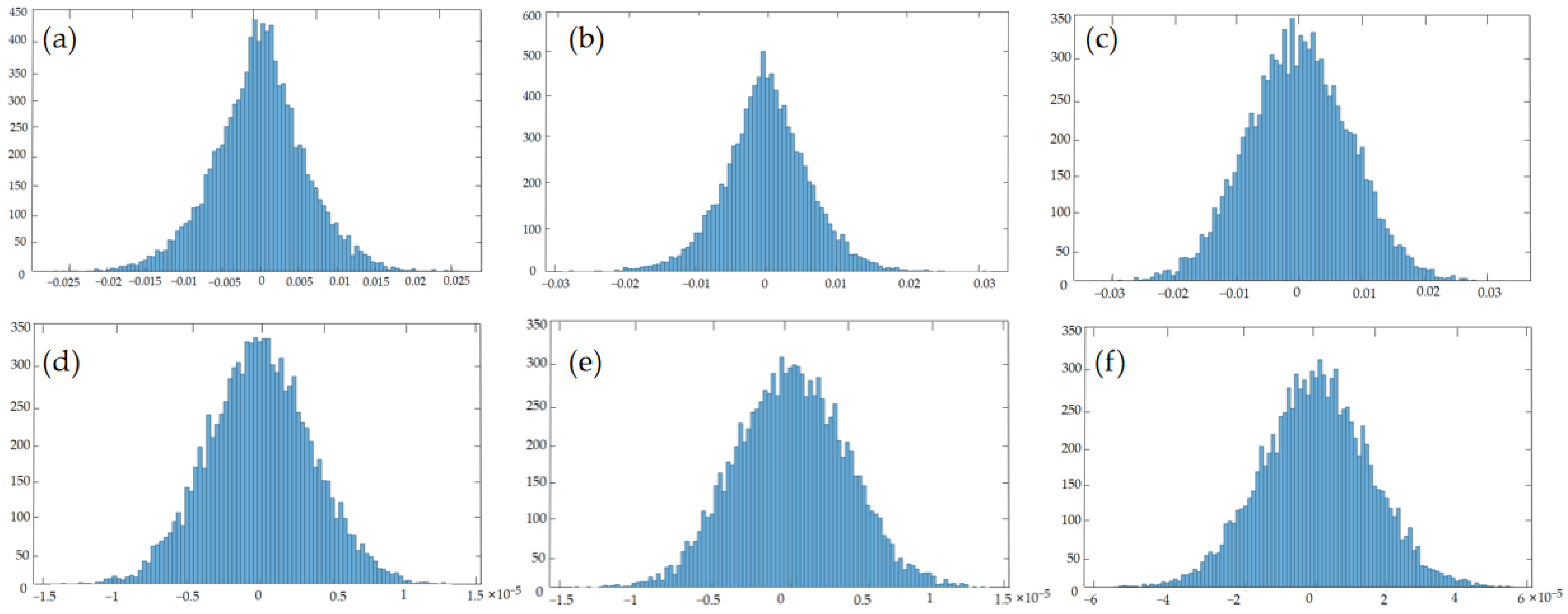
3.2. Optimization of Positioning Error of a Flexible Quick-Change Process System Based on the Monte Carlo Method

The relationship between the flexible quick-change process system and the six components of workpiece posture deviation is analyzed, predicted, and quantitatively described using the Monte Carlo method. Guaranteeing the improvement of the dimensional fit tolerance of each component of the flexible quick-change process system as well as the improvement of the mating type of the positioning elements, enhancing the flexibility of the system’s positioning accuracy.
q w = Δ x Δ y Δ z Δ α Δ β Δ γ = 0.02649 , 0.02559 mm 0.02741 , 0.02479 mm 0.03237 , 0.03225 mm 1.334 × 10 5 , 1.533 × 10 5 rad 1.293 × 10 5 , 1.485 × 10 5 rad 5.489 × 10 5 , 5.381 × 10 5 rad .
The displacement deviations Δx, Δy, and Δz in three directions and the rotation angle deviations Δx, Δy, and Δz around three axes are obtained individually by using the Monte Carlo model to carry out random sampling of the error source parameter variables and substituting them into the MATLAB R 2019 b error model for calculation, as the error distribution is shown in Figure 8.
From the figure, we can observe that the posture deviation distribution of the six components of the workpiece is extremely similar, all of which obey normal distribution in a certain range, whereas the influence degree of each error source on the posture deviation of the workpiece is different. In the deviation of workpiece posture, the rotation errors Δα and Δβ of the workpiece around the X- and Y-axes are relatively close, with a smaller error range, while the rotation angle error ∆γ around the Z-axis is more widely distributed, meaning that the limit error values that occur are greater, but all meet the technical requirements. In the displacement deviation, the distribution range of Δx and Δy errors is similar, while the distribution range of Δz errors is larger because the dowel pins limit the degrees of freedom of motion in the X- and Y-directions.
By analyzing the reasons, we can see that the distance between the installation holes of the inner ring and the outer ring of the fixture plate and the foundation plate is basically the same in the X- and Y-directions, while the positioning block will have a height difference on the Z-axis, so the error distribution on the Z-axis is relatively dispersed and the error distribution is large. In addition, it also shows that each error source has different degrees of influence on the displacement deviation of the workpiece in the three directions, and the Z-axis error is more sensitive.
According to the technical requirements of the flexible quick-change process system, all the error values should not be greater than 0.01 mm; hence, the axial error of the Z-axis failed to meet the technical demands. For that reason, it is necessary to conduct further optimization design for the foundation plate and fixture plate. Generally, the foundation plate is fixed to the machine tool; it does not need to be removed. The fixture plate must regularly be lifted, moved, and subjected to other operations while being directly attached to the fixture and the workpiece, which would reduce its accuracy. As a result, allow the Z-axis axial error of the flexible quick-change process system to be resampled with Monte Carlo sampling while allowing the design tolerance of the flatness of the fixture plate to be decreased to 0.01 mm. The outcomes are displayed in Figure 9.
After the flatness tolerance design of the fixture plate is optimized, the axial error of the Z-axis is [−0.02638 mm, 0.02453 mm]. At this point, the error value meets the technical requirements. Therefore, when designing the positioning element of the fixture, the influence of the deviation of each positioning element on the position error should be considered, and the sensitivity of each error source to the overall position and pose error of the workpiece should be analyzed. For the error source with higher sensitivity, the corresponding lower tolerance level is selected to improve the accuracy, along with the repeated positioning accuracy of the system.

3.3. Finite Element Simulation Analysis of a Flexible Quick-Change Process System

The flexible quick-change process system must be capable of adapting to load-bearing situations under various machining processes and machining settings. The finite element simulation model was established to study the influence law of the deformation error of flexible quick-change process systems under lifting and extreme working conditions.

3.3.1. Flexible Quick-Change Process System Lifting and Changing Process Error Analysis

The fixture plate experiences the combined effects of the tensile tension, workpiece load, etc., during the lifting and transposition processes of the flexible quick-change process system. The positioning pin put at the bottom will shift and produce mistakes because the center portion is not rigid enough and will bend and deform downward with a maximum deformation of 1.97 m. Additionally, the internal and external locating pins are arranged clockwise in accordance with the varied deformation directions of each locating pin, and the simulation outcomes are as follows in Figure 10.
The impact of a little corner deviation is not taken into account because the zero point clamping device has the capability of automatic clamping and centering, and there is a guiding chamfer at the fit. Consequently, the position deviations of the four positioning pins of the outer ring and the three positioning pins of the inner ring are each separately examined. Due to the deformation of the fixture plate, the positioning pins positioned on the bottom outer and inner rings will flex, producing an offset in the X-, Y-, and Z-axes. The errors produced are displayed in Table 1.
In the process of lifting and transposition, the fixture plate deforms downward, which will increase the inaccuracy produced by the outer ring positioning pins in the X- and Y-axes. Ulteriorly, the three locating pins in the inner ring at the bottom of the fixture plate are first fitted with the base of the zero positioning device, and then the four locating pins in the outer ring are fitted. As those inner ring positioning pins interact with the zero point clamping device for a longer period of time and are affected by gravity, a larger Z-axis error is produced with their use. Indicating that the planned foundation plate and the static mechanical properties of the lifting system meet the technical criteria, the deformation amount is within the design requirements, and the error brought on by the lifting transposition process can be disregarded.

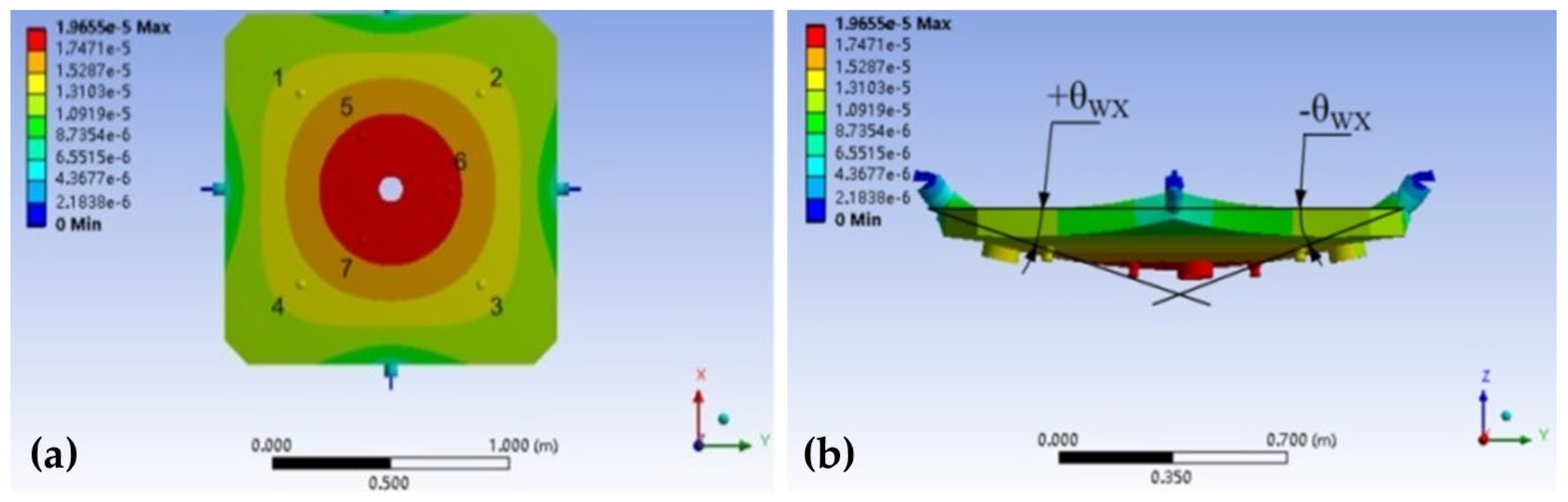
3.3.2. Flexible Quick-Change Process System Extreme Working Condition Error Analysis

In the machining process, the cutting force under difficult working conditions is employed as the applied load, and the coupling simulation of clamping force and cutting force is used to study the deformation and error change. Due to the symmetrical structure of the flexible quick-change process system, 16 constant cutting force load points are determined on the upper end of the workpiece, and the contact surface between the fixture plate and the workpiece is divided into eight areas, as shown in Figure 11a.
When the cutting load is machined at various points, the applied load causes the maximum deformation in the corresponding area of the fixture plate, accompanied by a dip angle of the fixture plate. This will affect the positioning error of the flexible quick-change process system. The adaptable fast change process system’s error flowchart for each load point under challenging circumstances is shown in Figure 11b. The error diagram for each load point can be used to determine the flexible quick-change process system’s error range under extreme operating conditions.
q w = Δ x Δ y Δ z Δ α Δ β Δ γ = 0 mm 0 mm 6.31 × 10 4 mm , 6.47 × 10 4 mm 3.4736 × 10 6 rad , 2.921 × 10 6 rad ± 4.7631 × 10 6 rad 0 rad .
The figure demonstrates the symmetrical distribution of errors at each load point under extreme conditions. The misregistration and deflection angles are both higher in the D and H zones, which are primarily related to the cutting force’s direction and the zero point clamping system’s distribution position. Nevertheless, the adaptable quick-change process system’s maximum error under extreme operating conditions is within the acceptable tolerance range and able to satisfy the technical criteria. The planned adaptable quick-change process system complies with the requirements for error accuracy, according to the finite element simulation analysis.

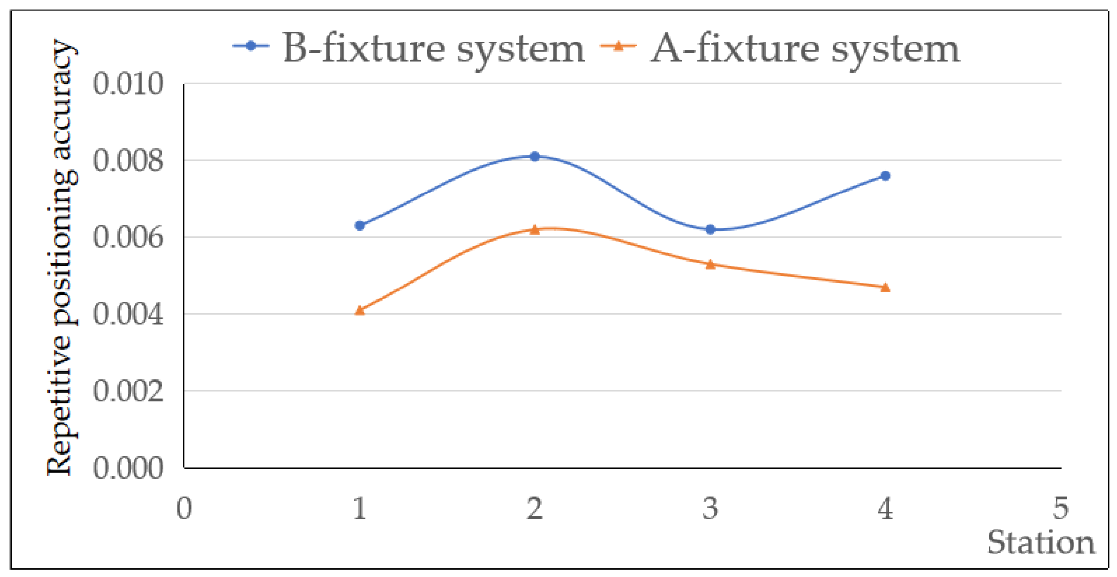
3.4. Functional Verification Experiment Analysis of the Flexible Quick-Change System

The versatile quick-change process system is produced in kind after a series of processing steps. The physical diagram of the developed and produced flexible quick-change process system is shown in Figure 12.
The manufacturing errors of the foundation plate and the two types of fixture plates A and B were measured with a Zeiss Accura CMM, which included the position errors of the two adjacent zero point clamping device mounting holes on the outer ring of the foundation plate, the position errors of the two adjacent positioning pin mounting holes on the outer ring of the fixture plate, and the flatness errors of the surfaces of the foundation plate and the fixture plate. The measurement results are shown in Table 2 below.
Taking the position accuracy of the center hole of the fixture plate as the reference, the fixture plate was repeatedly changed in the same station several times to measure its repetitive positioning accuracy, and the repetitive positioning accuracy of the two types of fixture plates A and B in different stations was measured. The measured results are shown in Figure 13. It is observed that the clamping accuracy meets the required clamping positioning accuracy of 0.01 mm (±5 μm), and its value lies in the prediction interval of the Monte Carlo method.
The quick-change system’s repetitive positioning precision differs between stations because the foundation plate and fixture plate were improperly machined. The repetitive positioning accuracy of fixture plate A in the same station is lower than that of fixture plate B. This is mostly explained by the larger size of fixture plate B, which has a larger position error and flatness error for each unit than fixture plate A. Moreover, fixture plate A deforms less under the load, which has less of an impact on positioning accuracy. It is obvious that flexible quick-change process technology is better suited for large aerospace component machining.

4. Conclusions

In this paper, aiming at the problems of difficult reassembly and low efficiency of large thin-walled cylindrical structural parts in the aerospace manufacturing industry, a design method of genetic algorithm and Monte Carlo method is proposed, and a high-precision and high-quality flexible quick-change process system with excellent performance is designed and developed, which is suitable for multiple varieties and multiple processes. The feasibility of the design research for the flexible quick-change process system is proved through finite element simulation and functional verification experiments:
(1)
The flexible quick-change process system is capable of quickly clamping off-line, moving machined pieces, and aligning them. In contrast to the flexible quick-change process system, which uses zero point clamping technology, each changeover only takes 2 min. This significantly reduces machine downtime by 79% and boosts changeover efficiency by 53%, ultimately increasing machining efficiency. Most importantly, the system provides a high level of repetitive positioning accuracy (0.0041–0.0081 mm);
(2)
The maximum shear force, torsion force, and overturning force that the flexible quick-change system can withstand are the vectorial combinations of the forces on each zero point clamping unit, and they all increase with the increase in the distribution number of zero point clamping units. However, with the same number of positioning units, the repeated positioning accuracy will increase with the increase in distance between the two zero point clamping units, and the applied force and the average strain of the system will be slightly changed. The “dot matrix” zero layout structure is determined through genetic algorithm optimization (four positioning units are squarely distributed in the outer circle and located in the position of the radius of the outer circle, which is 537.67 mm, and three positioning units are regular triangles distributed in the inner circle). By using the optimization algorithm, blind design based on experience can be avoided, and the flexible quick-change system can bear a greater load and have high positioning accuracy;
(3)
The Monte Carlo method was used to analyze the influence of system load and extreme working conditions on six components of workpiece pose deviation in the process of lifting transposition, and it was concluded that the displacement deviation and rotation angle deviation obeyed normal distribution within a certain range. However, each error source has a different sensitivity to the overall pose error of the workpiece. By optimizing the Z-axis flatness with a greater error sensitivity of 0.01 mm, the repetitive positioning accuracy of the system is controlled within 0.01 mm.

Author Contributions

Methodology, writing—review and editing, conceptualization, H.Z.; investigation, validation, Y.Z.; supervision, funding acquisition, C.L. and H.Z.; visualization, project administration, G.W. and Z.Z.; writing—original draft, formal analysis, data curation, J.W. and Y.Z. All authors have read and agreed to the published version of the manuscript.

Funding

This research was funded by the Foundation of Equipment Pre-Research Area, grant number 80923010401; the Research Project Supported by Shanxi Scholarship Council of China, grant numbers 2021109 and 2021118; the Fund Program for the Scientific Activities of Selected Returned Overseas Professionals in Shanxi Province, grant number 20210040; the key core technology and generic technology research of Shanxi, grant number 2020XXX005; and the National Natural Science Foundation of China, grant number 52075503.

Institutional Review Board Statement

Not applicable.

Informed Consent Statement

Not applicable.

Data Availability Statement

The original contributions presented in the study are included in the article; further inquiries can be directed to the corresponding author.

Conflicts of Interest

The authors declare no conflict of interest.

References

  1. Bao, Y.; Wang, B.; He, Z.X.; Kang, R.K.; Guo, J. Recent progress in flexible supporting technology for aerospace thin-walled parts: A review. Acad. J. Second. Mil. Med. Univ. 2022, 35, 10–26. [Google Scholar] [CrossRef]
  2. Yuan, Y.H.; Gu, D.D.; Lin, K.J.; Ge, Q.; Shi, X.Y.; Wang, H.R.; Hu, K.M. Influence of structural features on processability, microstructures, chemical compositions, and hardness of selective laser melted complex thin-walled components. Int. J. Adv. Manuf. Technol. 2020, 109, 1643–1654. [Google Scholar] [CrossRef]
  3. Hao, Q.L.; Yang, Q. A self-adaptive auxiliary fixture for deformation control in blade machining. Int. J. Adv. Manuf. Technol. 2020, 111, 1415–1423. [Google Scholar] [CrossRef]
  4. Ding, G.Z.; Wang, Y.F.; Yuan, S.M.; Lin, L.; Zhao, Z.C. Research on Rapid and Accurate Fixture Design for Non-Intervention Machining of Complex Parts. Metals 2022, 12, 1174. [Google Scholar] [CrossRef]
  5. Li, X.Y.; Yang, Y.F.; Li, L.; Shi, Y.W.; Zhao, G.L.; He, N.; Qian, N.; Mu, Z. An Approach for Optimising the Fixturing Configuration in Flexible Machining Fixtures. Int. J. Prod. Res. 2021, 59, 6223–6240. [Google Scholar] [CrossRef]
  6. Liu, Y.; Guan, S.X.; Zhao, H.; Liu, W.E.; Duan, L.C.; Sha, Y.D. Evolutionary Design of Machining Fixture Layout for Thin-Walled Structure. Math. Probl. Eng. 2022, 2022, 5216966. [Google Scholar] [CrossRef]
  7. Rex, F.M.T.; Hariharasakthisudhan, P.; Andrews, A.; Abraham, B.P. Optimization of flexible fixture layout to improve form quality using parametric finite element model and mixed discrete-integer genetic algorithm. Proc. Inst. Mech. Eng. C J. Mech. Eng. Sci. 2022, 236, 16–29. [Google Scholar]
  8. Aderiani, A.R.; Warmefjord, K.; Soderberg, R.; Lindkvist, L.; Lindau, B. Optimal design of fixture layouts for compliant sheet metal assemblies. Int. J. Adv. Manuf. Technol. 2020, 110, 2181–2201. [Google Scholar] [CrossRef]
  9. Wu, D.B.; Zhao, B.; Wang, H.; Zhang, K.Y.; Yu, J. Investigate on computer-aided fixture design and evaluation algorithm for near-net-shaped jet engine blade. J. Manuf. Process. 2020, 54, 393–412. [Google Scholar] [CrossRef]
  10. Wu, B.H.; Zheng, Z.Y.; Wang, J.; Zhang, Z.; Zhang, Y. Layout optimization of auxiliary support for deflection errors suppression in end milling of flexible blade. Int. J. Adv. Manuf. Technol. 2021, 115, 1889–1905. [Google Scholar] [CrossRef]
  11. Du, J.; Liu, C.H.; Liu, J.F.; Zhang, Y.S.; Shi, J.J. Optimal Design Of Fixture Layout For Compliant Part With Application In Ship Curved Panel Assembly. J. Manuf. Sci. Eng. 2021, 143, 061007. [Google Scholar] [CrossRef]
  12. Vinosh, M.; Raj, T.N.; Prasath, M. Optimization of Sheet Metal Resistance Spot Welding Process Fixture Design. Mater. Today Proc. 2021, 45, 1696–1700. [Google Scholar] [CrossRef]
  13. Ramesh, M.; Sundararaman, K.A. Development of Hybrid Artificial Neural Network–Particle Swarm Optimization Model and Comparison of Genetic and Particle Swarm Algorithms for Optimization of Machining Fixture Layout. Int. J. Precis. Eng. Manuf. 2022, 23, 1411–1430. [Google Scholar] [CrossRef]
  14. Qazani, M.R.C.; Parvaz, H.; Pedrammehr, S. Optimization of fixture locating layout design using comprehensive optimized machine learning. Int. J. Adv. Manuf. Technol. 2022, 122, 2701–2717. [Google Scholar] [CrossRef]
  15. Yu, K.G. Robust fixture design of compliant assembly process based on a support vector regression model. Int. J. Adv. Manuf. Technol. 2019, 103, 111–126. [Google Scholar] [CrossRef]
  16. Dosdoğru, A.T.; Göçken, M.; Geyik, F. Integration of genetic algorithm and Monte Carlo to analyze the effect of routing flexibility. Int. J. Adv. Manuf. Technol. 2015, 81, 1379–1389. [Google Scholar] [CrossRef]
  17. Munavalli, J.R.; Rao, S.V.; Srinivasan, A.; Van Merode, F. Dynamic Layout Design Optimization to Improve Patient Flow in Outpatient Clinics Using Genetic Algorithms. Algorithms 2022, 15, 85. [Google Scholar] [CrossRef]
  18. Liu, Z.; Hong, H.; Gan, Z.; Chen, Y.; Xing, K. Flexible Zoom Telescopic Optical System Design Based on Genetic Algorithm. Photonics 2022, 9, 536. [Google Scholar] [CrossRef]
  19. Zhao, X.S.; Tan, R.K.; Wang, Z.; Zou, X.C.; Hu, Z.J.; Sun, T. The Design and Implementation of a High-Precision Positioner Fixture. Micromachines 2021, 12, 1227. [Google Scholar] [CrossRef]
  20. Liu, Y.X.; Liang, Q.H.; Luo, L. Prediction and Analysis of Fixture Positioning Error Based on Monte Carlo Simulation. Mach. Des. Res. 2019, 35, 104–109+113. [Google Scholar]
  21. Guo, F.Y.; Liu, J.H.; Wang, Z.Q.; Zou, F.; Zhao, X.D. Positioning error guarantee method with two-stage compensation strategy for aircraft flexible assembly tooling. J. Manuf. Syst. 2020, 55, 285–301. [Google Scholar] [CrossRef]
  22. Butt, S.U.; Arshad, M.; Baqai, A.A.; Saeed, H.A.; Din, N.A.; Khan, R.A. Locator Placement Optimization For Minimum Part Positioning Error During Machining Operation Using Genetic Algorithm. Int. J. Precis. Eng. Manuf. 2021, 22, 1169. [Google Scholar] [CrossRef]
  23. Yang, F.Y.; Xing, Y.F.; Li, X.X. A comprehensive error compensation strategy for machining process with general fixture layouts. Int. J. Adv. Manuf. Technol. 2020, 107, 2707–2717. [Google Scholar] [CrossRef]
  24. Peng, D.Q.; Wang, L.M.; Shao, Y.M. Position prediction and error compensation for a large thin-walled box-shaped workpiece in a fixture. Int. J. Adv. Manuf. Technol. 2021, 116, 2633–2649. [Google Scholar] [CrossRef]
Figure 1. Initializing the layout. (a) Layout I (six outside and four inside). (b) Layout II (four outside and four inside). (c) Layout III (four outside and three inside). (d) Layout IV (three outside and three inside).
Applsci 13 06482 g001
Figure 2. Layout polar coordinates.
Applsci 13 06482 g002
Figure 3. Flexible quick-change process system-workpiece and error source. (a) Flexible quick-change process systems and workpieces. (b) The system error source.
Applsci 13 06482 g003
Figure 4. Error model of a flexible quick-change process system.
Applsci 13 06482 g004
Figure 5. Error Schematic. (a) Position error. (b) Posture error.
Applsci 13 06482 g005
Figure 6. Mechanical analysis of a flexible quick-change process system.
Applsci 13 06482 g006
Figure 7. Optimized layout by genetic algorithm.
Applsci 13 06482 g007
Figure 8. Error distribution diagram. (a) X-direction displacement error. (b) Y-direction displacement error. (c) Z-direction displacement error; (d) X-axis rotational error. (e) Y-axis rotational error. (f) Z-axis rotational error.
Applsci 13 06482 g008
Figure 9. Rotation angle error around the Z-axis after optimization.
Applsci 13 06482 g009
Figure 10. Simulation of a flexible quick-change process system for lifting and changing positions. (a) Simulation results of lifting and changing processes. (b) Positioning pin position change.
Applsci 13 06482 g010
Figure 11. (a) The distributions of turning cutting force loads and deformation areas. (b) Error at each load point under extreme operating conditions.
Applsci 13 06482 g011
Figure 12. Structure diagram of a flexible quick-change process system. (a) foundation plate and zero point clamping system. (b) fixture plate. (c) flexible quick-change process system-workpiece.
Applsci 13 06482 g012
Figure 13. Repetitive positioning accuracy measurement results.
Applsci 13 06482 g013
Table 1. Positioning pin error during lifting transposition.
X-Axis (ΔX)Y-Axis (ΔY)Z-Axis (ΔZ)
Outer ring positioning pin3.8 × 10−3 mm3.8 × 10−3 mm1.52 × 10−5 mm
Inner ring positioning pin3.2 × 10−3 mm2 × 10−3 mm1.96 × 10−5 mm
Table 2. Physical error measurement results.
Foundation PlateFixture Plate AFixture Plate B
Position error (mm)0.0026~0.00940.0012~0.01280.0023~0.0098
Flatness error (mm)0.01140.00670.0079
Disclaimer/Publisher’s Note: The statements, opinions and data contained in all publications are solely those of the individual author(s) and contributor(s) and not of MDPI and/or the editor(s). MDPI and/or the editor(s) disclaim responsibility for any injury to people or property resulting from any ideas, methods, instructions or products referred to in the content.

