Abstract
An acoustic black hole (ABH) has been applied in the regulation of structural performance to form the aggregation effect of elastic waves in the local area of the structure, which has been used in energy harvesting in recent years. The piezoelectric vibration energy harvester (VEH) integrated with the beam of a bilateral periodic 1D ABH is proposed in this study. The theoretical model of the proposed VEH is established and analyzed based on the transfer matrix method. The performance of the VEHs is numerically simulated by COMSOL Multiphysics. The simulation results show that the performance of the bilateral ABH beam is higher than its traditional counterpart. Finally, the performance of the proposed VEH is validated in an experimental system. The experimental results show that the peak output voltage of the VEH Model 3 can reach 169.16 V, which is 1.9 times that of the traditional one. In the optimal impedance matching, the output power of the third bilateral VEH is 2.7 times that of the traditional ABH, which can reach 91.52 mW.
1. Introduction
Vibrations can be seen anywhere in industrial production and the surrounding circumstances, especially in structures such as beams or rods in civil engineering and mechanical engineering [1,2,3]. This kind of redundant vibration is usually harmful and severely affects reliability and accuracy in various mechanical and precision equipment [4,5]. However, the health status of the mechanical equipment and engineering structures can be monitored by wireless sensor network (WSN) nodes in real time. Traditional WSN [6] nodes are powered by batteries, which have a limited lifetime and are hard to maintain, especially in harsh environments and remote areas. Therefore, it is extremely important to develop a novel power supply method that can replace batteries with a long lifetime and is easy to maintain.
Harvesting energy from the vibrations in the surrounding environment where the WSN nodes are deployed, which can be converted to electrical energy, should be a possible solution. The device that can harvest vibration energy and convert it to electrical energy is a vibration energy harvester (VEH). VEHs can be divided into piezoelectric, electromagnetic and electrostatic types according to the operation principle. The piezoelectric VEH has wide employment through its simple structure and high electromechanical transfer coefficient [7]. A cantilever is used as the primary structure of a traditional piezoelectric VEH with a narrow operation bandwidth and low harvesting efficiency.
The nonlinear effect can be used to improve the performance of traditional VEHs. Nonlinear structures are widely used due to their simple structure, which can be integrated into the cantilever beam in a VEH. As a nonlinear structure, the ABHs have wide employment in the field of vibrational reduction, noise reduction and energy harvesting due to the unique energy focus effect. ABHs have structures with geometrical or material parameters gradually decreasing t in thin-walled components such as beams and benches, which can focus the elastic wave [8]. Gao et al. [9,10,11] proposed several kinds of one-dimensional double-leaf ABH beams with nested damping units, unit periodic arrays and spatial V-shaped bending. The low-frequency band gap and vibration characteristics of the structure were analyzed. The application of an ABH structure in energy harvesting has gained a lot of attention in recent years. Deng [12] uses the Lagrange equation to derive the combined equation of the bending vibration of the ABH beam with the piezoelectric layer. The influence of the parameters of the ABH and piezoelectric layer on energy harvesting efficiency is analyzed. Zhao et al. [13] established an electromechanical coupling model of an ABH cone structure with a surface-mounted piezoelectric transducer and analyzed the dynamic response with numerical simulation. Simulation results show that the response of the system is better than the traditional structure. Ji et al. [14] proposed an energy harvester integrated with a high-intensity ABH and validated it through experimental tests.
In addition, the characteristic that acoustic black holes can gather energy is also applicable to vibration suppression. Du et al. [15] proposed a new solution to embed 2D ABHs on the support plate to suppress the transmission of compressor vibration to the refrigerator body. Liang et al. [16] focus on the mid- and low-frequency performance of plates embedded with the array of an ABH for energy focalization and vibration and noise suppression. Lyu et al. [17] proposed a type of metamaterial plate enabling in-plane ultra-wide vibration isolation in engineering equipment development and experiments show that the effective attenuation ability is compared with the traditional hexagonal lattice.
A piezoelectric VEH with a bilateral periodic 1D ABH is proposed in this paper. The vibration energy can be accumulated in the center of the ABH due to the focus effect and converted into electrical energy by the piezoelectric plates attached to the ABH surface. The theoretical model of the energy harvester with a bilateral periodic 1D ABH structure is established, and the performance of the above VEH is discussed through numerical simulation in COMSOL and verified by experimental tests.
2. VEH Integrated with Bilateral Periodic 1D ABH
2.1. Structure of VEH
The traditional VEH with an ABH is a cantilever beam with a unilateral ABH embedded. As shown in Figure 1, a VEH with a bilateral 1D ABH structure is proposed, where the piezoelectric plates attached to the ABH are ignored. Three different types of VEHs with an ABH are designed and analyzed.
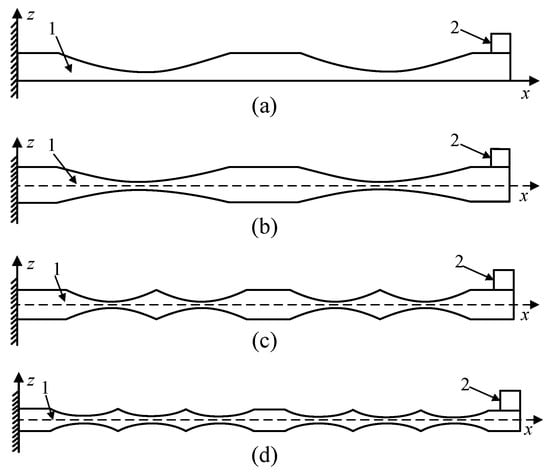
Figure 1.
Structure diagram of ABH beam: (a) traditional 1D ABH beam, (b) bilateral 1D ABH Model 1, (c) bilateral 1D ABH Model 2, (d) bilateral 1D ABH Model 3 (1: major structure; 2: quality mass).
The collection of vibration energy is realized by the ABHs embedded in the cantilever of the VEH. The operation bandwidth can be adjusted by tuning the parameters of ABHs and the attached mass. The mass added to the edge of the beam greatly reduces the natural frequency of the VEH (The VEHs discussed next all contain mass blocks).
2.2. Operation Principle of VEH
As shown in Figure 2, the thickness of the ABH fits the formula h(x) = εxm, where h(x) and represents the thickness variation of the beam; ε is the undetermined coefficient and m is a power exponent. The structural stiffness is ensured by extending the ABH portion to a truncated platform at a minimum thickness, which is determined by the fabrication process. The operation principle of the proposed VEH is as follows: Vibration is generated in the cantilever beam when an external excitation signal is applied on the constrained end. The elastic waves according to the vibration are transmitted in the cantilever beam and concentrated in the center of the ABH zone due to the focus effect. The concentrated vibration energy is converted into electrical energy by the attached piezoelectric plate in the center of the ABHs.
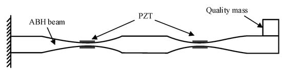
Figure 2.
Structure diagram of piezoelectric energy harvester.
2.3. Dynamic Modeling of ABH Beam
As shown in Figure 3, the left side of the beam is fix constrained and the right side is left free. It is assumed that the external excitation is applied at 0.1 xL from the left end, where Y0 is the amplitude of the external excitation, and P is its frequency. The thickness of the constant thickness part of the beam is hm, xA is the length of a single ABH unit, ht is the truncated thickness of the ABH and xt is the truncated extended platform length. The adverse effects of the truncated platform can be offset to some extent by properly adding damping material to the surface of the curved portion of the ABH. xE is the length of the periodic joint in the middle and xL is the total length of the beam.
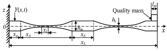
Figure 3.
Bilateral one-dimensional periodic ABH beam Model 1.
The shear deformation of the cantilever beam is neglected because the length of the ABH beam is much larger than its thickness, and the transverse vibration is dominant in practice. The undamped transverse vibration equation of the beam based on the Euler–Bernoulli beam theory is [18]:
where ρ is the material density of the ABH beam, is the cross-section area of the beam and is the bending moment of the beam.
The ABH beam is a variable cross-section beam, which can be approximately equivalent to a linear combination of N equal cross-section beams as shown in Figure 4. When the N is large enough, the ABH beam can be approximated by the equivalent segmented beam, and then the vibration of the equivalent beam is analyzed by the transfer matrix method. The transfer matrix method is that any uniform beam in the segmented beam is analyzed separately to determine its corresponding transfer matrix, and then the whole beam is combined and analyzed according to the continuity between the segmented beams to obtain the whole vibration response of the ABH beam.
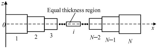
Figure 4.
Sectional diagram of ABH beam.
For the single-section uniform beam after discretization, if the damping layer is neglected, the transverse free vibration equation of the number i uniform beam can be expressed as [19]:
Let and be the components of the beam in the x-axis and z-axis directions, respectively, as shown in Figure 5. The shear and rotation of the beam are ignored since the thickness of the beam is much smaller than its length, where r and θ are the beam’s axial strain and rotation angle after flexural deformation. Then, the length of the deformed element can be expressed as [20]:
and the axial strain of the beam is:
the axial strain of the beam can be neglected when the excitation of the ABH beam is mainly transverse vibration, which means r = 0. At this time, the following can be obtained:
by substituting Equation (5) into Equation (6), the rotation angle θ can be expressed as:
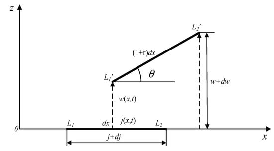
Figure 5.
Geometric relationship of the deformed element.
The Taylor expansion of Equation (7) can be obtained:
the curvature of the beam element after deformation can be expressed as:
it can be obtained that the nonlinear strain generated by the ABH beam during vibration is:
Without considering the damping layer, the bending moment of the uniform beam in the first section number i can be expressed as:
where is the inner stress of the ABH beam, b is the width of the ABH beam, substituting the stress–strain constitutive relation and Equation (10) into Equation (11), the bending moment of the uniform beam number i can be expressed as:
where is the elastic modulus of the beam, and is the section moment of inertia of the number i uniform beam, which is expressed as:
substituting Equation (12) into Equation (2), the vibration equation of the number i uniform beam is written as:
The entire ABH beam is composed of multiple uniform beams after discretization, and the cross-section area and cross-section moment of the inertia of each uniform beam are different. The composite parameters of each node are introduced as follows:
in summary, the transfer matrix method mechanical model of the ABH beam considering the nonlinear strain can be expressed as:
3. Simulation and Analysis
3.1. Structure and Material
The response of the VEH with a bilateral 1D ABH is simulated and compared with a traditional VEH with a traditional 1D ABH. The cutting length of each ABH region is set to 90 mm for simplicity. The geometry parameters of these structures are listed in Table 1.

Table 1.
Parameters of ABH beams.
3.2. Simulation of VEH with ABHs
3.2.1. Natural Frequency of ABH Beams
The grid division in the FEM model of the ABH beam (take bilateral 1D ABH Model 1 as an example) is shown in Figure 6. As shown in Figure 7, the left end of the VEH is fix-constrained (the red arrow indicates the initial stress distribution under the external force at the free end), the right end is attached with a mass block and set free and the natural frequencies are acquired, as shown in Figure 8. The natural frequency of the ABH beams decreases with the increment of the ABH arrays. The specific frequency values in the figure are shown in Table A1 in Appendix A.

Figure 6.
Grid division of beam in COMSOL.
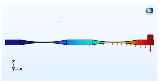
Figure 7.
Simulation diagram of beam in COMSOL.
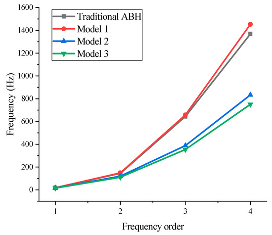
Figure 8.
First four-order natural frequency.
3.2.2. Transient Response under Gaussian Pulse
The characteristic of a Gaussian pulse is energy concentration, which is beneficial to compress the signal spectrum and reduce the adjacent channel interference. The excitation in the actual environment can be better simulated by Gaussian pulses. The broadband Gaussian pulse is used as the excitation signal during the transient simulation of the VEH with ABHs. The formula of the broadband Gaussian pulse is as below:
The Gaussian pulse has a wide frequency band and short excitation time, and its center frequency is set to 3000 Hz. Time domain and frequency domain images of Gaussian pulses are shown in Figure 9 and Figure 10, respectively. In the simulation, a given displacement of 5 × 10⁻⁵ m is loaded in the rightmost boundary of the beam to obtain an ideal excitation effect. The energy focus effect here of the ABH is reflected by the energy density of the ABH region, which can be validated by calculating the focused energy of the ABH zone. The Gaussian impulse response in the time domain is shown in Figure 11. Simulation results show that the energy focus effect of the ABH increased with the number of ABH arrays.
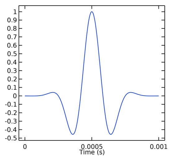
Figure 9.
Normalized time domain for Gaussian pulse.
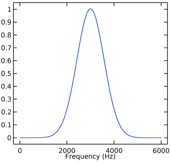
Figure 10.
Normalized frequency domain for Gaussian pulse.
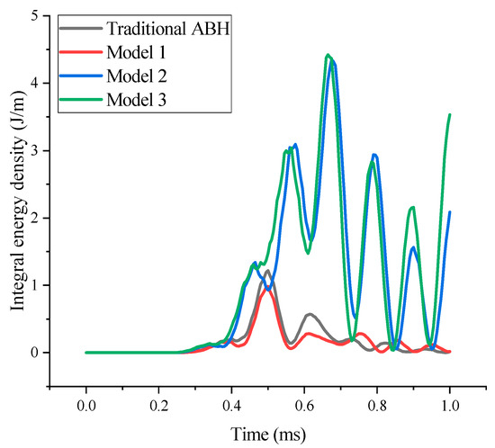
Figure 11.
Integral energy density of ABH region under Gaussian pulse.
The kinetic energy density and strain of ABH Model 1 are shown in Figure 12. It can be seen that the energy is mainly concentrated in the acoustic black hole. The kinetic energy density nephograms of the other three structures are shown in Appendix A.
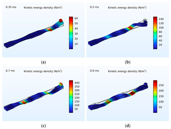
Figure 12.
Kinetic energy density and strain of ABH Model 1: (a) ABH in 0.35 ms, (b) ABH in 0.5 ms, (c) ABH in 0.7 ms, (d) ABH in 0.9 ms.
The response of the VEH with ABHs under Gaussian pulse is transformed by FFT, as shown in Figure 13. The VEH with more ABH periodic arrays can store more vibration energy in a wide frequency range of around 3000 Hz.
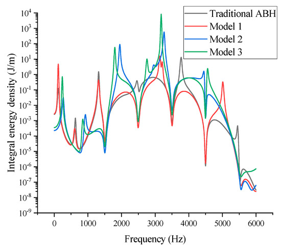
Figure 13.
Integral energy density of ABH region under Gaussian pulse (FFT).
3.2.3. Analysis in Frequency Domain
The analysis of these structures in a frequency domain is implemented under the condition that the rightmost end is applied with a 5 N force. The frequency band is divided into low frequency (0–2000 Hz), intermediate frequency (2000–4000 Hz) and high frequency (4000–6000 Hz). The response of the four VEHs with the ABH is compared with the velocity of the surfaces of the ABH central platform, as shown in Figure 14. Then, the root mean square (RMS) processing is performed on the simulation results, so the overall response of each structure in different frequency bands is observed, as shown in Figure 15.
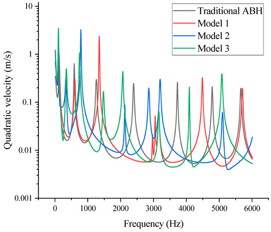
Figure 14.
The quadratic velocity of ABH region.
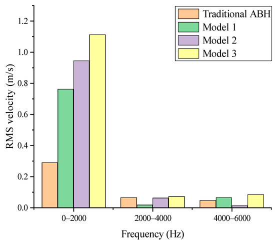
Figure 15.
The RMS velocity of ABH region.
As shown in Figure 14, the VEH with a bilateral ABH can obtain higher vibration energy mainly concentrated in the low-frequency range. Figure 15 shows that the RMS vibration velocity of the bilateral ABH structure is higher than the traditional counterpart, and the vibration velocity of Model 3 is about 3.84 times that of the traditional ABH in the low-frequency range.
4. Experimental Test
4.1. Experimental System
The performance of VEHs with ABHs is tested in an experimental system. The main components of the experimental platform are shown in Figure 16.
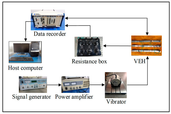
Figure 16.
Experimental system for energy harvesting performance.
The working process of the whole experimental system is as follows: the signal generated by the signal generator will be amplified by the power amplifier to drive the vibrator to vibrate, and the electrical signal generated by VEH will be collected by the data recorder and transmitted to the host computer for display.
The prototype of four different models of VEHs is shown in Figure 17. These beams were fabricated by 3D printing and the piezoelectric plates with a size of 20 × 12 × 0.3 mm were pasted on the ABH part. The specific parameters of each structure are consistent with Table 1.
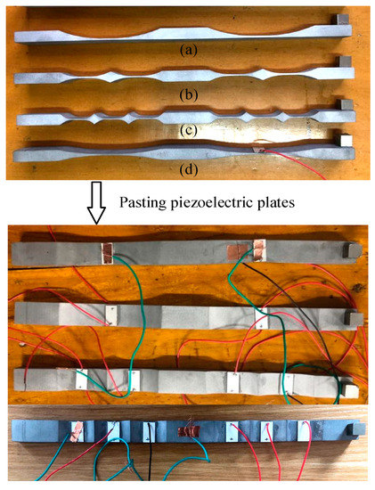
Figure 17.
Energy harvester structure: (a) traditional 1D ABH beam, (b) bilateral 1D ABH Model 2, (c) bilateral 1D ABH Model 3, (d) bilateral 1D ABH Model 1.
These beams are made of AlSi10Mg, the attached mass block is iron and the attached piezoelectric plate is made of PZT-5H with a 0.3 mm thickness truncated platform. The parameters of the material are listed in Table 2.
Table 2.
Parameters of size and material of energy harvester.
4.2. Results and Discussion
4.2.1. Output Voltage of VEH with ABH
The output voltage of VEHs with an ABH in the frequency domain is shown in Figure 18, where the external load resistance is 10 kΩ. The peak output voltage of the VEH with a traditional ABH is 8.5 V at 153 Hz, and the peak output voltage of the VEH with the bilateral ABH Model 1 is 10.5 V at 146 Hz separately. The peak output voltage of the VEH with ABH Model 2 is 22.1 V at 140 Hz, and the peak output voltage of the VEH with ABH Model 3 is 29.2 V at 130 Hz. The peak output voltage of the VEH with the ABH increased with the number of ABH arrays. The peak output voltage of VEH Model 3 is 3.4 times that of the traditional counterpart. The specific natural frequency and output voltage are shown in Table A2 in Appendix A.
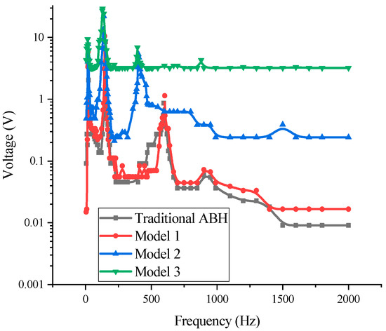
Figure 18.
Voltage frequency response of several beams.
A comparison of the experimental and simulated natural frequencies of the VEHs is shown in Table 3. The deviation between the simulation and experiment is mainly due to the insufficient precision of actual machining and the vibration interference of the vibrator itself cannot be completely eliminated.
Table 3.
Comparison of natural frequency.
4.2.2. Optimal Impedance Matching of VEH with ABH
The second value of the natural frequency of each structure is used as the frequency of the external excitation, and the impedance matching is performed under the sinusoidal excitation with an amplitude of 3 N. The output voltage and power of VEHs with an ABH in the optimal impedance matching are shown in Figure 19 and Figure 20.
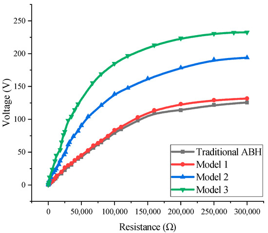
Figure 19.
Output voltage of VEHs with different load resistances.
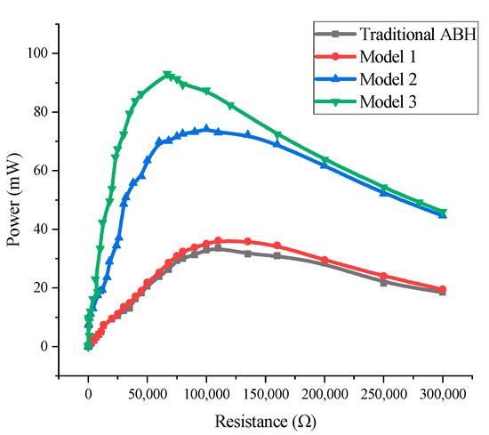
Figure 20.
Output power of VEHs with different load resistances.
The optimal impedance value of the traditional VEH with an ABH is 115 kΩ, the output peak voltage is 84.78 V and the output power reaches 33.63 mW. The optimal value of VEH Model 1 is 110 kΩ, the output peak voltage is 88.36 V and the output power reaches 35.62 mW. The optimal value of VEH Model 2 is 100 kΩ, the output peak voltage is 137.58 V, and the output power reaches 75.01 mW. The optimal value of VEH Model 3 is 67 kΩ, the output peak voltage is 169.16 V, and the output power is 91.52 mW. The peak output voltage of VEH Model 3 is 1.9 times that of the VEH with the traditional ABH, and the peak output power of VEH Model 3 is 2.7 times that of the VEH with a traditional ABH. The harvesting efficiency of the VEH with an ABH can be improved significantly with the number of ABH arrays.
4.2.3. Transient Voltage Response Test of VEH with ABH
Each VEH with an ABH is excited with a sinusoidal signal in its second natural frequency, which is connected with optimal impedance matching. The transient voltage response of each VEH is measured under sinusoidal excitation with an amplitude of 3 N.
Figure 21 shows the time domain response of the transient output voltage of VEHs at optimal impedance. The average output voltage of each VEHs is shown in Figure 22. The average output voltage increases with the number of ABH arrays.
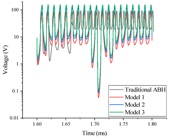
Figure 21.
Transient output voltage of VEHs in optimal impedance.
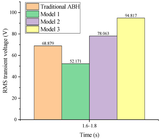
Figure 22.
Transient average output voltage of VEHs with optimal impedance.
5. Conclusions
A piezoelectric VEH with a bilateral periodic one-dimensional ABH is proposed in this paper. First, the energy focus effect of an ABH in the VEH is simulated by COMSOL under a Gaussian pulse excitation. The simulation results show that the beam with a bilateral ABH is easier to generate more energy with than the traditional one. The performance of the VEHs with an ABH is tested in an experiment. The experimental results show that the output voltage and power of the VEH with a bilateral periodic 1D ABH is higher compared with the VEH with a traditional one-dimensional ABH and increased with the number of ABH arrays. The main research results are as follows:
- (1)
- After the best impedance matching is completed: the output power of the traditional VEH reaches 33.63 mW, that of VEH Model 1 can reach 35.62 mW, that of VEH Model 2 can reach 75.01 mW and that of VEH Model 3 can reach 91.52 mW.
- (2)
- Under the same external conditions: the output voltage of the traditional VEH reaches 84.78 V, that of VEH Model 1 can reach 88.36 V, that of VEH Model 2 can reach 137.58 V and that of VEH Model 3 can reach 169.16 V.
The energy harvesting performance of VEH Model 3 is the best. The results show that the energy collection efficiency will increase with the increase in the ABH arrays. It is expected that the proposed VEH with an ABH may provide an effective energy supply option for WSN sensor nodes, help to monitor the life of some equipment and, finally, promote green and sustainable development.
Author Contributions
Conceptualization, Z.Z. and H.W.; methodology, Z.Z. and C.Y.; software, Z.Z.; validation, H.W. and H.S.; formal analysis, Z.Z. and C.Y.; investigation, H.W. and H.S.; resources, C.Y.; data curation, H.W.; writing—original draft preparation, Z.Z. and Y.Y.; writing—review and editing, H.W. and Y.Y.; visualization, Z.Z. and H.W.; supervision, C.Y.; project administration, H.W. and C.Y.; funding acquisition, H.W. All authors have read and agreed to the published version of the manuscript.
Funding
Support was received from the overseas study visit and training program for outstanding young backbone talents of Anhui Province (gxgwfx2021035); the innovation team of Anhui Polytechnic University; the Special Display and Imaging Technology Anhui Technology Innovation Center open project support (2020AJ06001), Anhui Polytechnic University—Jiujiang District Industrial Collaborative Innovation Special Fund Project (2022cyxtb4); the Anhui Provincial Natural Science Foundation (No. 1908085QA13); the National Natural Science Foundation of China (No. 11902001) and the Natural Science Research Project of Institutions of Higher Education in Anhui Province (No. KJ2017A114).
Institutional Review Board Statement
Not applicable.
Informed Consent Statement
Not applicable.
Data Availability Statement
Not applicable.
Conflicts of Interest
The authors declare no conflict of interest.
Appendix A

Figure A1.
Kinetic energy density and strain of traditional ABH: (a) ABH in 0.35 ms, (b) ABH in 0.5 ms, (c) ABH in 0.7 ms, (d) ABH in 0.9 ms.


Figure A2.
Kinetic energy density and strain of ABH model 2: (a) ABH in 0.35 ms, (b) ABH in 0.5 ms, (c) ABH in 0.7 ms, (d) ABH in 0.9 ms.

Figure A3.
Kinetic energy density and strain of ABH Model 3: (a) ABH in 0.35 ms, (b) ABH in 0.5 ms, (c) ABH in 0.7 ms, (d) ABH in 0.9 ms.
Table A1.
First four-order natural frequency in simulation.
Table A1.
First four-order natural frequency in simulation.
| Order Number/Structure | Traditional | Model 1 | Model 2 | Model 3 |
|---|---|---|---|---|
| 1 (Hz) | 18.143 | 18.183 | 16.446 | 15.222 |
| 2 (Hz) | 144.95 | 149.64 | 120.74 | 110.51 |
| 3 (Hz) | 643.7 | 657.18 | 388.83 | 353.96 |
| 4 (Hz) | 1368.3 | 1452.7 | 833.02 | 750.32 |
Table A2.
First four-order natural frequency and output voltage in experiment.
Table A2.
First four-order natural frequency and output voltage in experiment.
| Order Number/Structure | Traditional | Model 1 | Model 2 | Model 3 |
|---|---|---|---|---|
| 1 (Hz) | 20 | 20 | 18 | 17 |
| Output voltage (V) | 4.08 | 5.83 | 7.82 | 9.36 |
| 2 (Hz) | 153 | 146 | 140 | 130 |
| Output voltage (V) | 8.48 | 10.52 | 22.08 | 29.21 |
| 3 (Hz) | 595 | 603 | 403 | 395 |
| Output voltage (V) | 0.86 | 1.14 | 5.34 | 6.89 |
| 4 (Hz) | 900 | 900 | 800 | 780 |
| Output voltage (V) | 0.06 | 0.07 | 0.63 | 4.3 |
References
- Bosso, N.; Magelli, M.; Zampieri, N. Application of low-power energy harvesting solutions in the railway field: A review. Veh. Syst. Dyn. 2021, 59, 841–871. [Google Scholar] [CrossRef]
- Chen, F.; Yang, C.; Guo, Z.; Wang, Y.; Ma, X. A Magnetically Controlled Current Transformer for Stable Energy Harvesting. IEEE Trans. Power Deliv. 2022, 38, 212–221. [Google Scholar] [CrossRef]
- Li, Z.; Yan, Z.; Luo, J.; Yang, Z. Performance comparison of electromagnetic energy harvesters based on magnet arrays of alternating polarity and configuration. Energy Convers. Manag. 2019, 179, 132–140. [Google Scholar] [CrossRef]
- Li, Y. Design and Implementation of Electrostatic Energy Harvesters with Green Nanomaterials. Ph.D. Thesis, University of Guelph, Guelph, ON, Canada, 2018. [Google Scholar]
- Yang, Y.; Wang, S.; Stein, P.; Xu, B.X.; Yang, T. Vibration-based energy harvesting with a clamped piezoelectric circular diaphragm: Analysis and identification of optimal structural parameters. Smart Mater. Struct. 2017, 26, 045011. [Google Scholar] [CrossRef]
- Qi, L.; Pan, H.; Pan, Y.; Luo, D.; Yan, J.; Zhang, Z. A review of vibration energy harvesting in rail transportation field. Iscience 2022, 25, 103849. [Google Scholar] [CrossRef] [PubMed]
- Li, H.; Doaré, O.; Touzé, C.; Pelat, A.; Gautier, F. Energy harvesting efficiency of unimorph piezoelectric acoustic black hole cantilever shunted by resistive and inductive circuits. Int. J. Solids Struct. 2022, 238, 111409. [Google Scholar] [CrossRef]
- Krylov, V.V. New type of vibration dampers utilising the effect of acoustic ‘black holes’. Acta Acust. United Acust. 2004, 90, 830–837. [Google Scholar]
- Gao, N.; Wang, B.; Lu, K.; Hou, H. Complex band structure and evanescent Bloch wave propagation of periodic nested acoustic black hole phononic structure. Appl. Acoust. 2021, 177, 107906. [Google Scholar] [CrossRef]
- Gao, N.; Wei, Z.; Hou, H.; Krushynska, A.O. Design and experimental investigation of V-folded beams with acoustic black hole indentations. J. Acoust. Soc. Am. 2019, 145, EL79–EL83. [Google Scholar] [CrossRef] [PubMed]
- Gao, N.; Wei, Z.; Zhang, R.; Hou, H. Low-frequency elastic wave attenuation in a composite acoustic black hole beam. Appl. Acoust. 2019, 154, 68–76. [Google Scholar] [CrossRef]
- Deng, J.; Guasch, O.; Zheng, L.; Song, T.; Cao, Y. Semi-analytical model of an acoustic black hole piezoelectric bimorph cantilever for energy harvesting. J. Sound Vib. 2021, 494, 115790. [Google Scholar] [CrossRef]
- Zhao, L.; Conlon, S.C.; Semperlotti, F. Broadband energy harvesting using acoustic black hole structural tailoring. Smart Mater. Struct. 2014, 23, 065021. [Google Scholar] [CrossRef]
- Ji, H.; Liang, Y.; Qiu, J.; Cheng, L.; Wu, Y. Enhancement of vibration based energy harvesting using compound acoustic black holes. Mech. Syst. Signal Process. 2019, 132, 441–456. [Google Scholar] [CrossRef]
- Du, X.; Fu, Q.; Zhang, J.; Zong, C. Numerical and Experimental Study on Suppression Effect of Acoustic Black Hole on Vibration Transmission of Refrigerator Compressor. Appl. Sci. 2021, 11, 8622. [Google Scholar] [CrossRef]
- Liang, H.; Liu, X.; Yuan, J.; Bao, Y.; Shan, Y.; He, T. Influence of Acoustic Black Hole Array Embedded in a Plate on Its Energy Propagation and Sound Radiation. Appl. Sci. 2022, 12, 1325. [Google Scholar] [CrossRef]
- Lyu, X.; Ding, Q.; Ma, Z.; Yang, T. Ultra-Wide Bandgap in Two-Dimensional Metamaterial Embedded with Acoustic Black Hole Structures. Appl. Sci. 2021, 11, 11788. [Google Scholar] [CrossRef]
- Sun, J.Q. Vibration and sound radiation of non-uniform beams. J. Sound Vib. 1995, 185, 827–843. [Google Scholar] [CrossRef]
- Wagg, D.; Neild, S. Nonlinear Vibration with Control; Springer: New York, NY, USA, 2010. [Google Scholar]
- Nayfeh, A.H.; Mook, D.T. Nonlinear Oscillations; Wiley: New York, NY, USA, 1995. [Google Scholar]
Disclaimer/Publisher’s Note: The statements, opinions and data contained in all publications are solely those of the individual author(s) and contributor(s) and not of MDPI and/or the editor(s). MDPI and/or the editor(s) disclaim responsibility for any injury to people or property resulting from any ideas, methods, instructions or products referred to in the content. |
© 2023 by the authors. Licensee MDPI, Basel, Switzerland. This article is an open access article distributed under the terms and conditions of the Creative Commons Attribution (CC BY) license (https://creativecommons.org/licenses/by/4.0/).