Abstract
In recent years, more and more attention has been paid to research on variable geometry turbine engines with the increasing requirement of engine performance. Variable geometry turbine technology can significantly improve the operating performance of aero engines. Adjusting the working angle of the turbine guide vane can change the thermodynamic cycle of the engine operation, so that the turbine can respond to different engine operating conditions. Variable geometry turbines work in harsh environments. Therefore, the design of the variable geometry turbine needs to consider the effect of thermal deformations of the mechanism on operational stability. There are few research studies on variable geometry turbine adjusting mechanisms. This paper established the numerical calculation models of two adjusting mechanisms by integrating fluid mechanics, heat transfer, and dynamic theories, which are paddle and push–pull rod mechanisms. The models were applied to study the effects of components’ thermal deformations and flexible bodies on the motion characteristics of the adjusting mechanism. Furthermore, the performance of the two adjusting mechanisms was compared. The calculation results show that the paddle rod adjusting mechanism can accurately adjust the angles of guide vanes. The paddle rod adjusting mechanism has a larger driving stroke and smaller driving force than the push–pull rod adjusting mechanism. The paddle adjustment mechanism was better suited to the operational requirements of the variable geometry turbine. The research results of this paper are relevant to the design of variable geometry turbine regulation structures.
1. Introduction
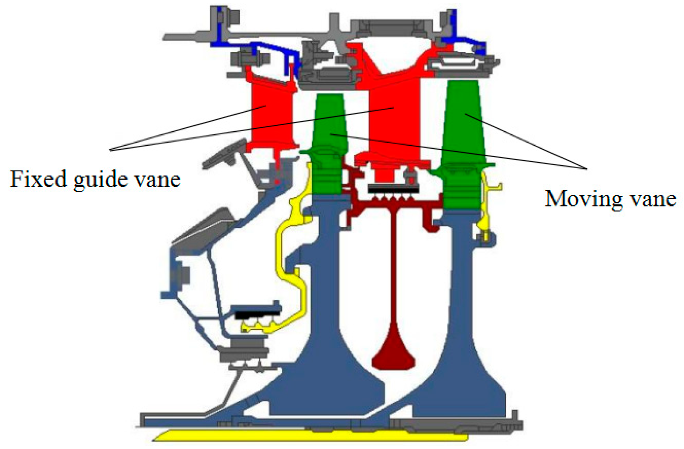
Figure 1 shows the conventional engine turbine structure. The guide vanes of the conventional engine turbine are fixed. They cannot rotate. Figure 2 shows the variable geometry engine turbine structure. The guide vanes of the variable geometry engine turbine are not fixed. They can rotate.

Figure 1.
Turbine structure of conventional engine.

Figure 2.
Turbine structure of variable geometry engine.
The variable geometry turbine is a crucial component of the variable cycle engine. The research on variable geometry turbines has received attention at home and abroad. The adjustable guide vane angle is the leading way to realize the variable geometry turbine. It is also the main research direction of the variable geometry turbine. The design idea is to install a set of mechanical adjustment mechanisms outside the engine casing. The guide vanes are driven to rotate by the adjusting mechanism. Through the rotation of the guide vanes, the working angles of the guide vanes are changed. This changes the exhaust area of the turbine guide structure. It realizes the adjustment of the work distribution between the high-pressure rotor and the low-pressure rotor. Its main feature is to change the flow matching between the moving blade and the guide vane in the turbine. The airflow area in the turbine passage is changed. The overall working performance of the turbine is improved [1,2]. The candidate engine F120 of the American F22 fighter is a variable-cycle engine. The turbine guide vane adjustment of 7° can bring about a 10% flow change in the machine [3].
In recent years, variable cycle engines have been a new development direction for turbines. However, achieving variable geometry functionality required work. It was necessary to consider various factors, such as operating environment, structural space, and functional implementation. The compressor could realize variable geometry functions. Rotating guide vanes and variable geometry structures were the main research directions. Paweł Wirkowski [4] studied the application of mathematical models to analyze the dynamic process in gas turbines. The influence of variable geometry compressors on airflow characteristics was introduced in detail, making it possible to numerically simulate the aerodynamics of variable geometry compressors [5] with rotating guide vanes in the future. Han et al. [6] conducted a numerical study of airflow characteristics in a centrifugal compressor. A comparison was conducted between the nonguide vane scheme and the scheme with guide vanes. At different conditions, the efficiency of the intake chamber of the compressor had increased by 4.97% on average. Wang et al. [7] studied numerical simulation and optimization analysis on the working mechanism of variable guide vanes in transonic compressors. The joint angle of a seven-stage transonic compressor was optimized. A new phenomenon had been discovered where the angle adjustment affected its performance and that of adjacent downstream blades and the performance of upstream blades. At different angle openings, joint adjustment optimization improved efficiency by 0.2–1.93%. A. Romagnoli et al. [8] introduced the experimental research results of turbochargers with different designs. The turbocharger was designed as a single-inlet and dual-inlet turbocharger with a variable geometry structure. A significant depreciation in efficiency was measured between the single- and twin-entry configurations due to the mixing effects. The nozzles unit provided the best compromise in performance at different speeds.
Variable geometry compressors were easier to achieve variable cycle performance compared to turbines. Because compressors did not need to consider the effects of high-temperature thermal deformations and flexible bodies, this was significantly different from variable geometry turbines. The gas turbine blades were scoured by high-temperature gas sustainedly and long term in harsh environments. It was significant to explore effective cooling methods to lower the turbine blade temperature [9] to ensure the gas turbine’s safe and stable operation. Zhang et al. [10] and Xu et al. [11] studied the impact of cooling and heat transfer characteristics in the turbine guide vane cavity. A numerical simulation of multihole impingement cooling of a turbine guide vane cavity [12] with a complex pin fin structure was conducted. Xin et al. [13] carried out a numerical simulation of a radial intake chamber with guide vanes with self-guide grooves. Guide vanes could improve and enhance the flow and efficiency of the airflow within the compressor. José et al. [14] developed a 3D printed model with variable geometry turbine static components, blades, and the volute. Moreover, a numerical simulation study of the model was conducted. The effect of tip clearance on tip leakage flow was also studied. In addition, the increase in the clearance radius led to a disorderly flow in the impeller [15]. The total dissipation rate on the impeller suction side and near the impeller inlet increased with the backflow clearance radius, but that on the impeller [16] suction side decreased with the increase of the backflow clearance radius. The total dissipation rate of the guide vane’s suction side and the outlet passage’s wall decreased with the increased backflow clearance radius. Liang et al. [17] studied the effect of the sealing chamber leakage flow rate on the performance of aviation engines. They found that when the sealing tooth gap span ratio increased by 1%, the total pressure ratio decreased by 2.6%, and the efficiency decreased by 0.6%. The leakage flow rate of the sealing chamber significantly impacted the engine’s overall performance.
Szymon Fulara et al. [18] proposed that variable geometry systems had great potential due to enhanced thermal management and flow control. Variable burner cooling and variable area nozzle (VAN) systems could improve gas turbine performance and reduce pollutant emissions. Dariusz et al. [19] studied three different variable geometric positions and three different turbine speeds of a two-stage system. The result proposed a new idea for turbines with variable blade geometry to solve the problem of low turbine efficiency [20]. Djordje S. Cantrak et al. [21] conducted experimental research on turbulent eddies behind an axial flow fan installed in a pipeline on a test bench with a free inlet and a pipeline outlet. Turbulent vortices in many turbine systems [22] consumed enormous amounts of energy.
The variable guide vane structure was applied in compressors and gas turbines and was widely used in water turbines. Yang et al. [23] found that high-amplitude and high-frequency pressure fluctuations caused by rotor–stator interaction (RSI) had become the primary hydraulic excitation source of the unit structure, which might cause severe vibration and fatigue damage to structural components, seriously affecting the safe operation of the unit. Li et al. [24] studied the effect of eight different inlet slopes of guide vanes on the performance of axial flow pumps. The numerical simulation results were verified through experiments [25]. The numerical simulation results indicated that reducing the height of the guide vane hub could improve the head and efficiency of the axial flow pump. Jesline Joy et al. [26] proved this concept by introducing a variable guide vane system into the draft tube of the high-head Francis turbine. A variable guide vane structure was added to the draft tube of the hydraulic turbine. The guide vane could rotate ±45° around the shaft. This structure could reduce pressure pulsation. In contrast, it had a negligible impact on the hydraulic performance of the hydraulic turbine. Megavath Vijay Kumar et al. [27] studied the performance characteristics of the Francis turbine at different guide vane openings. They found the optimal operating point based on the number of units.
At present, variable geometry turbines are still a new research direction. There is broad research space. It is not easy to achieve variable cycle functions for variable geometry turbines. Because the turbine structure is located behind the combustion chamber, the working environment of turbine guide vanes is very harsh. The guide vanes are subjected to long-term impact from high-temperature and high-pressure gas. There are few studies on the influence of components’ thermal deformations and flexible bodies on the regulating rule of guide vanes. The research of this paper fills this gap.
The paper’s primary goal is to study the angle-regulating rule of guide vanes of the two variable geometry turbine adjusting mechanisms, that is, the relationship between the angle of the guide vane and the driver displacement. The guide vanes of the turbine are enclosed in the inner casing. It is an enclosed space, which is not easy to inspect. For example, the turbine is working. Determining the angle of a circle of guide vanes is difficult. However, with the angle-regulating rule, the angle of the guide vanes can be determined by observing the driver displacement. At the same time, the influence of components’ thermal deformations and flexible bodies on the regulating rule of guide vanes is studied.
2. Rigid–Flexible Coupling Analysis Considering Multiflexible Bodies and Components’ Thermal Deformations
2.1. Computational Model
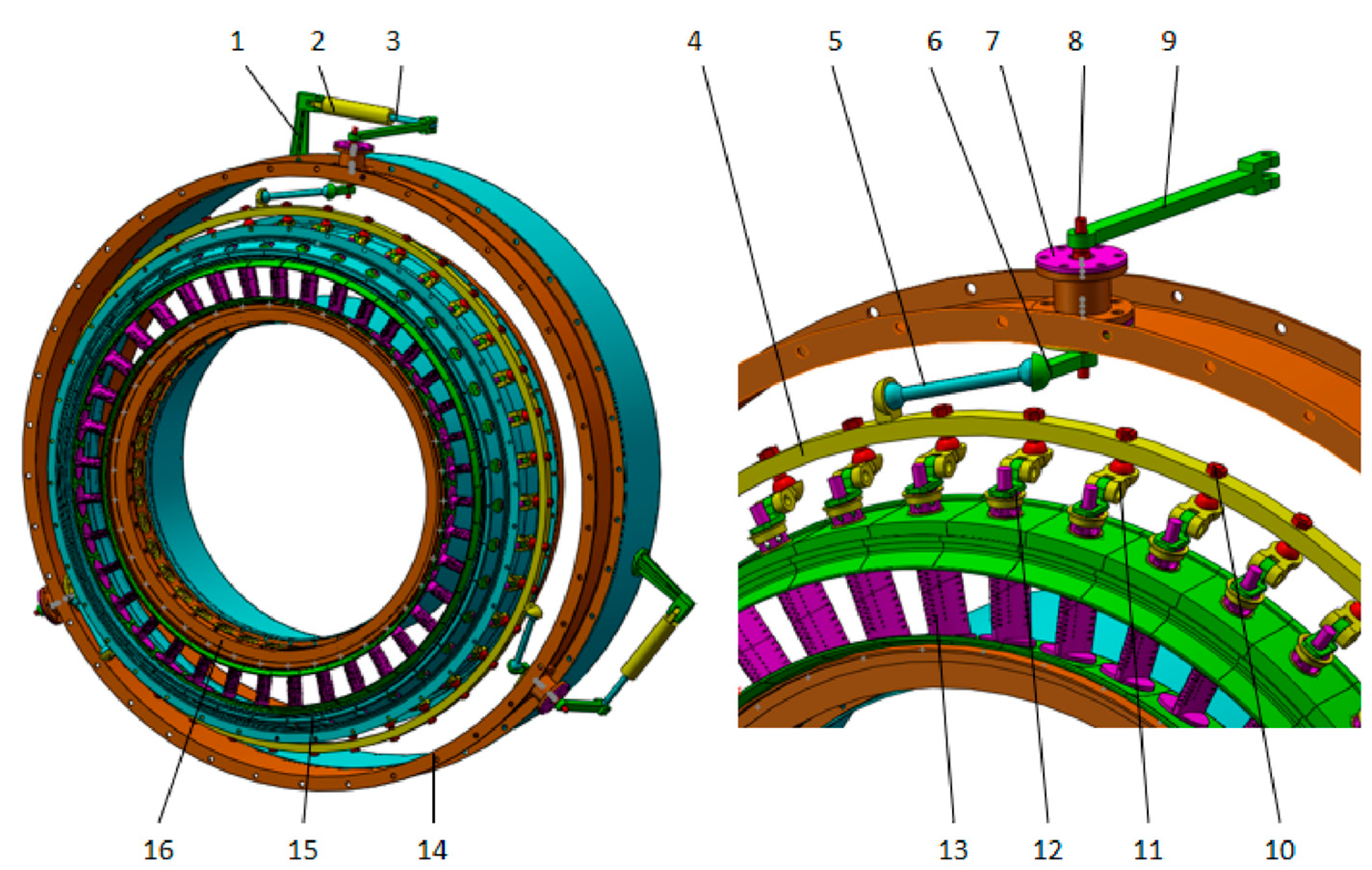
The paper’s primary research is the regulating rule of the deflection angle of guide vanes with driver displacement on the two variable geometry turbine adjusting mechanisms. In another paper, the torque on the shaft of guide vanes was obtained. The paper conducts a torque analysis on guide vanes of the variable geometry turbine adjusting mechanism. The torque of the guide vane is applied to the calculation model. At the same time, multiflexible bodies and components’ thermal deformations of the adjusting mechanism are also applied to the calculation model. Finally, the regulating rule of the deflection angle of guide vanes with driver displacement is obtained. Furthermore, the performance of the two adjusting mechanisms is compared. The calculation model in this paper has two kinds of adjusting mechanisms: a paddle rod adjusting mechanism and a push–pull rod adjusting mechanism. Figure 3 shows the three-dimensional model of the three drivers’ adjusting mechanisms with a paddle rod. Figure 4 shows the three-dimensional model of the three drivers’ adjusting mechanism with a push–pull rod. The diameter of the outer casing is 1048 mm. The diameter of the inner casing is 862.6 mm. The diameter of the inner support ring is 614 mm. The height of the guide vane is 147.8 mm. The width of the guide vane is 58.2 mm. The diameter of the outermost shell is 1248 mm. The diameter of the innermost shell is 444 mm. The length of the airflow stroke of this turbine stage is 253.3 mm.
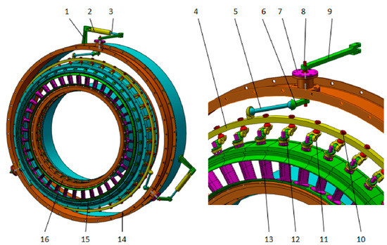
Figure 3.
Three-dimensional model of three drivers’ adjusting mechanism with paddle rod. 1—Base, 2—Hydraulic cylinder, 3—Piston rod, 4—Linkage ring, 5—Pull rod, 6—Paddle, 7—Bearing block, 8—Shaft, 9—Guide rod, 10—Pin, 11—Arm I, 12—Arm II, 13—Guide vane, 14—Outer casing, 15—Inner casing, 16—Inner support ring.
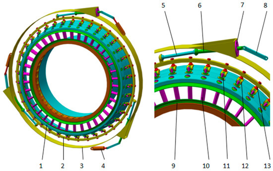
Figure 4.
Three-dimensional model of three drivers’ adjusting mechanism with push–pull rod. 1—Inner casing, 2—Linkage ring, 3—Outer casing, 4—Hydraulic cylinder, 5—Pull rod, 6—Push rod, 7—Linear bearing, 8—Connecting rod, 9—Inner support ring, 10—Guide vane, 11—Arm II, 12—Arm I, 13—Pin.
2.2. Calculation Settings
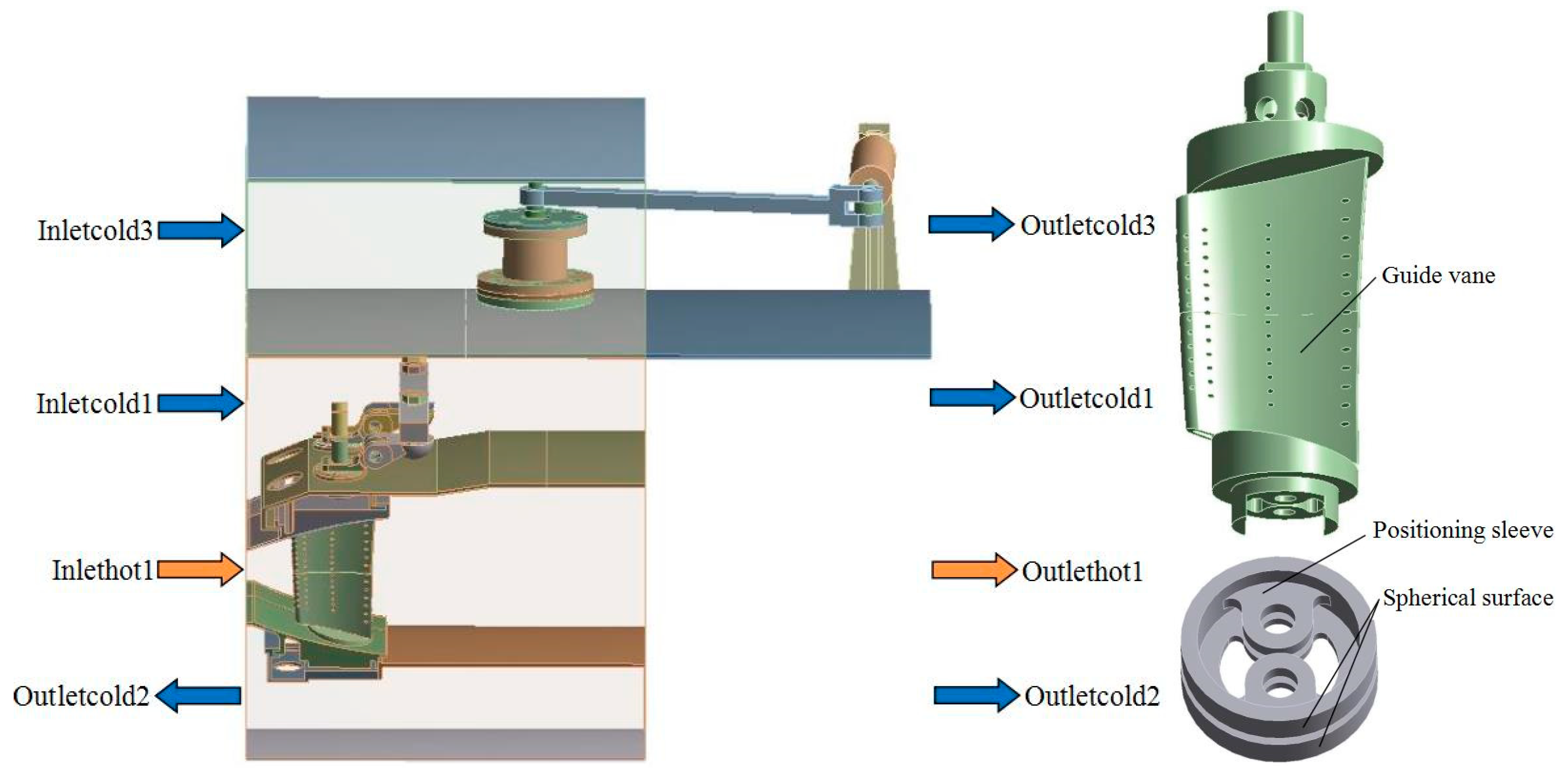
The regulating rule of the deflection angle of guide vanes with driver displacement was solved. First, the heat–fluid–solid coupling calculation was carried out for the calculation model through FLUENT. It obtained the thermal deformations of the two adjusting mechanisms. Second, the flexible bodies of components were obtained through ANSYS. It established a rigid–flexible coupling model of multiflexible bodies with two adjusting mechanisms. Finally, the kinematic and dynamic analysis of the model was carried out through Adams. It is a three-dimensional rigid–flexible coupling calculation model, including thermal deformations of components and multiflexible bodies. The experimental data of the institute provide the boundary conditions. The gas inlet temperature was 1273.15K. The inlet temperatures of cold air were 473.15K, 573.15K, and 673.15K, respectively. Table 1 shows the pressure and temperature boundary conditions at gas and cold air inlet and outlet. Figure 5 shows the inlet and outlet of gas and cold air. The cold air enters the outer channel from the cold air inlet (Inletcold1). Cold air enters the lower chamber through the inner holes of the guide vanes and positioning sleeves. At the same time, another part of cold air enters the main channel through the small holes on the guide vane body. The cold air and hot gas are mixed in the inner channel. The positioning sleeve is fixed at the lower end of the guide vane. The cylindrical surface of the positioning sleeve is designed as a spherical surface to reduce friction. The temperature of the inner channel is very high. The positioning sleeve is prone to jamming due to thermal expansion. Table 2 shows the computation method and model conditions. The computational domain is the entire fluid domain and the solid domain. The fluid type is compressible mixed gas. The turbulence model is k-ε Model. The two cascaded sides are periodic symmetric boundaries. The other walls are nonslip adiabatic walls.

Table 1.
Boundary conditions of gas and cold air inlet and outlet.

Figure 5.
Gas and cold air inlet and outlet.
Table 2.
Computation method and model conditions.
2.3. Meshing
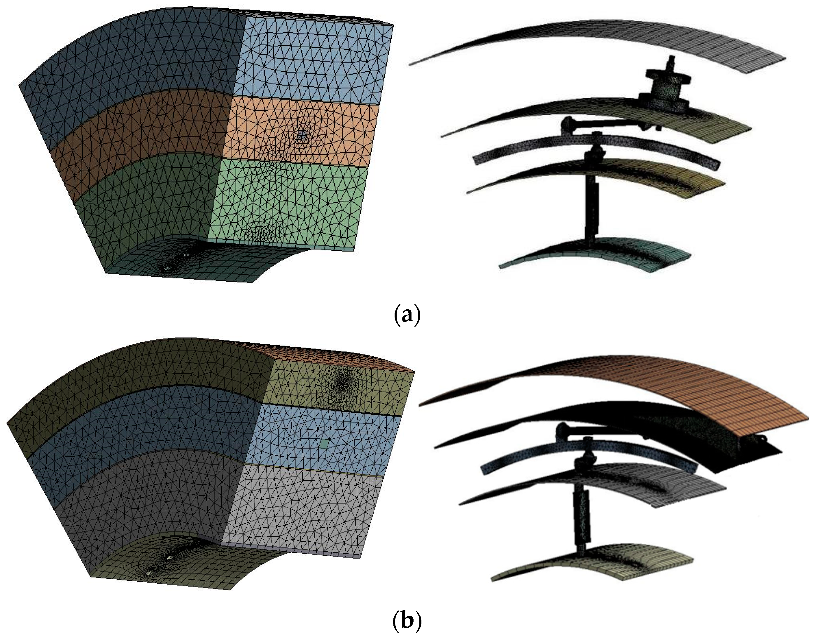
Computational domain meshing is the key to numerical simulation. Figure 6 shows the calculation model grid. The solid domain was enveloped in the fluid domain. The solid domain cannot be seen. The solid domain is displayed separately on the right. The quality of the mesh directly affects the accuracy of numerical results. It also directly affects the convergence of the calculation results. Therefore, proper mesh type selection and maximum mesh quality improvement are crucial to achieving high-precision numerical simulation [28,29].

Figure 6.
Meshing of the two adjusting mechanisms. (a) Fluid domain and solid domain of paddle rod adjusting mechanism; (b) fluid domain and solid domain of push–pull rod adjusting mechanism.
The paper used the particular preprocessing software GAMBIT of FLUENT for mesh generation. It can quickly generate high-quality unstructured meshes. It has certain advantages in dealing with complex geometric models. The main criterion of mesh quality is mesh distortion. The mesh distortion is smaller, and the quality of the generated mesh is higher. Generally speaking, regular objects can be divided into tetrahedral meshes. Its distortion will be relatively smaller.
2.4. Material Settings
Each component material of the two adjusting mechanisms was established. These components are made of titanium alloy TC4. They are pin, arm I, arm II, linkage ring, bushing I, and bushing II. The material of these components is superalloy GH4169. They are positioning sleeve, inner support ring, sealing ring, and inner casing. The material of these components is cast superalloy K417G. They are guide vane, inner ring block, and outer ring block. The transmission shaft is made of stainless steel 0Cr17Ni4Cu4Nb. These components are made of stainless steel 1Cr11Ni2W2MoV. They are paddle, pull rod, bearing block, piston rod, guide rod, and outer casing. Table 3 shows the characteristic parameters of each material.
Table 3.
Material characteristic parameters.
2.5. Calculation Process
The heat–fluid–solid coupling calculation was carried out for three-dimensional models of the two adjusting mechanisms through FLUENT. It can obtain the pressure field and temperature field of the two adjusting mechanisms. The thermal deformations of the two mechanisms were obtained through the static structural module. The thermal deformation models of the two mechanisms were brought into the ANSYS module. The modal neutral files of the two mechanisms were obtained. The multiflexible body models of the two mechanisms were obtained. The kinematic and dynamic analysis of the model was carried out through Adams. It is a three-dimensional rigid–flexible coupling calculation model, including thermal deformations of components and multiflexible bodies. The regulating rule of the deflection angle of guide vanes with driver displacement was obtained. Figure 7 shows the calculation process.
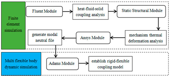
Figure 7.
Calculation process.
3. Results and Discussion
3.1. Temperature Field Analysis
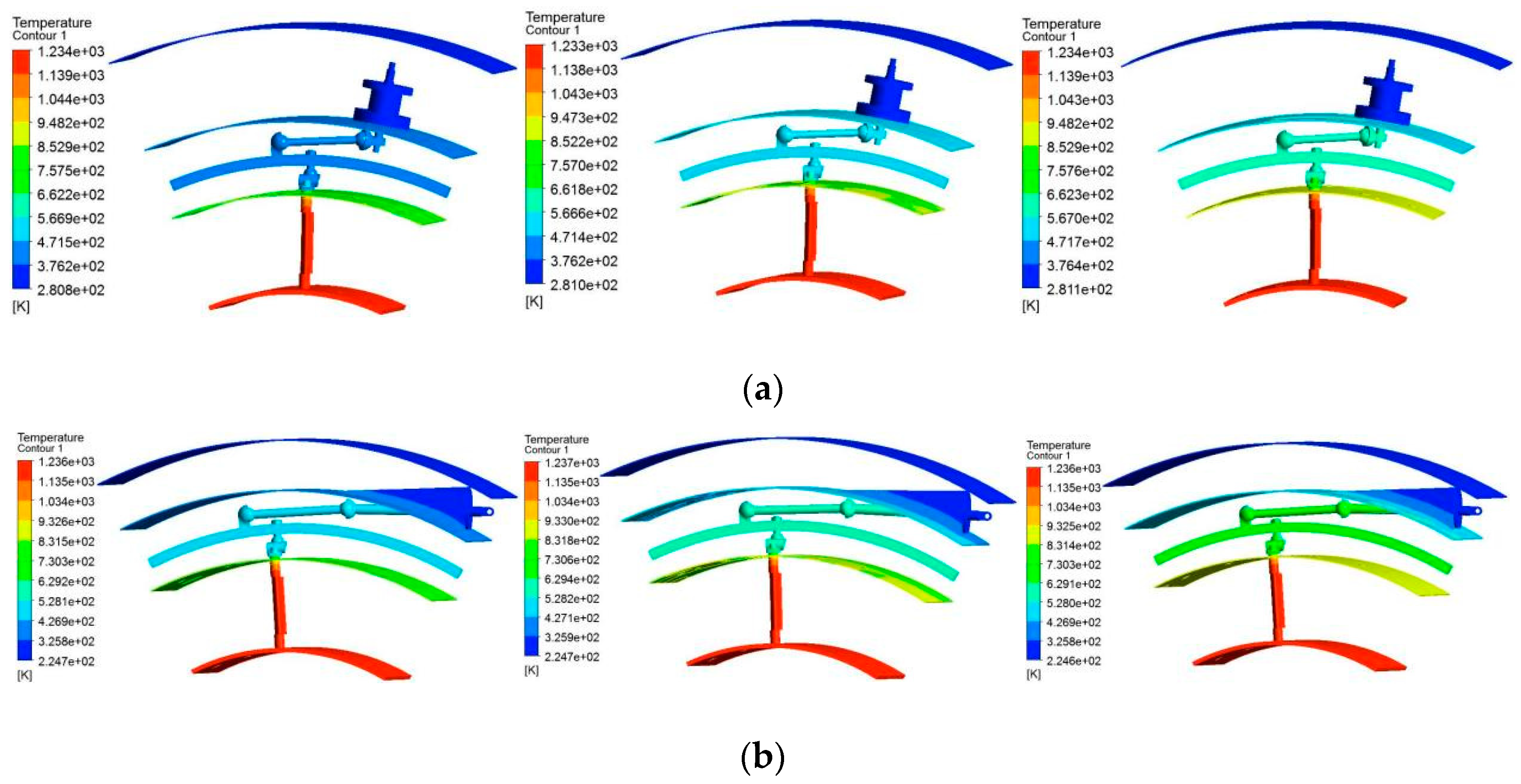
Figure 8 shows the temperature load distribution at the three working conditions. Table 4 shows the operating temperature range of the two adjusting mechanisms. The cold air inlet temperatures of the two adjusting mechanisms are 473.15K, 573.15K, and 673.15K, respectively. It can be seen from Figure 8 that the temperature presents a prominent gradient distribution layer by layer among the inner channel, outer channel, and outer shell. The components of the two adjusting mechanisms mainly work in the outer channel. They are in the middle layer. When the cold air inlet temperatures are 473.15K, 573.15K, and 673.15K, the operating temperature ranges of the paddle rod adjusting mechanism components are 376.2K to 852.9K, 471.4K to 947.3K, and 567K to 1043K. When the cold air inlet temperatures are 473.15K, 573.15K, and 673.15K, the operating temperature ranges of the push–pull rod adjusting mechanism components are 325.8K to 831.5K, 427.1K to 933K, and 528K to 1034K.
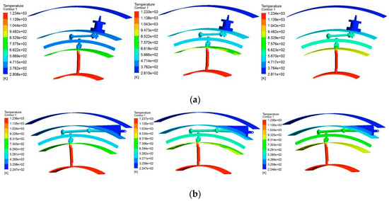
Figure 8.
Temperature distribution of the two adjusting mechanisms. (a) Paddle rod adjusting mechanism at 473.15K, 573.15K, and 673.15K; (b) Push–pull rod adjusting mechanism at 473.15K, 573.15K, and 673.15K.
Table 4.
Operating temperature range of the two adjusting mechanisms.
3.2. Thermal Deformation Analysis
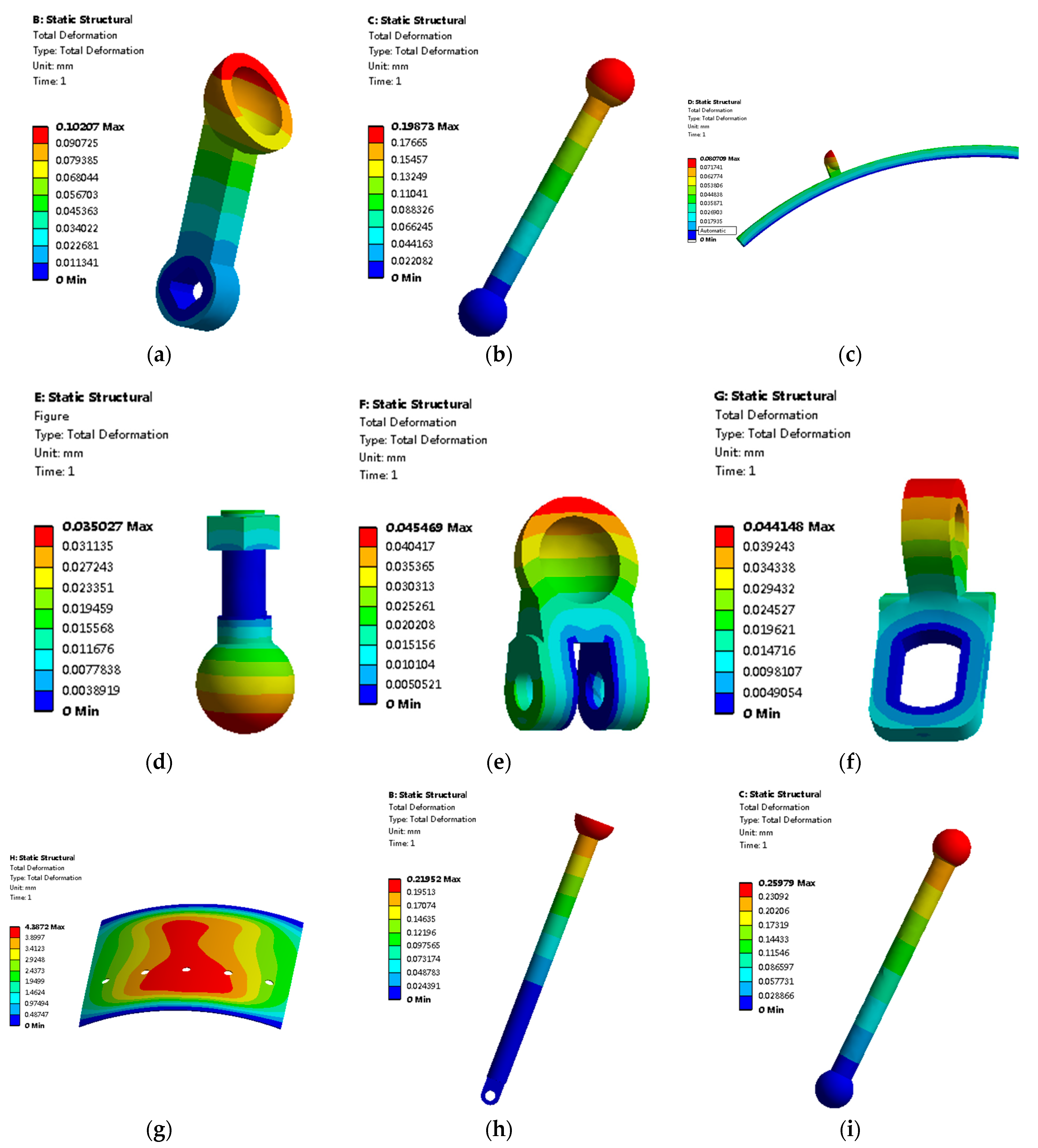
Figure 9 shows the thermal deformation distribution at the working temperature of 473.15K. Table 5 shows the thermal deformation distribution of components at different temperatures. The cold air inlet temperatures of the two adjusting mechanisms are 473.15K, 573.15K, and 673.15K, respectively. It can be seen from Figure 9 that the thermal deformation presents apparent gradient distribution. The adjusting mechanism components expand with heat. The thermal deformation of components will increase. The inlet temperatures of cold air are 473.15K, 573.15K, and 673.15 K. The thermal deformations of the paddle are 0.10207 mm, 0.16592 mm, and 0.23051 mm, respectively. The thermal deformations of pull rod I are 0.19873 mm, 0.31913 mm, and 0.44125 mm, respectively. The thermal deformations of the linkage ring are 0.08071 mm, 0.12971 mm, and 0.17914 mm, respectively. The thermal deformations of the pin are 0.03503 mm, 0.05705 mm, and 0.07918 mm, respectively. The thermal deformations of arm I are 0.04547 mm, 0.07374 mm, and 0.10225 mm, respectively. The thermal deformations of arm II are 0.04415 mm, 0.06949 mm, and 0.09513 mm, respectively. The thermal deformations of the inner casing are 4.3872 mm, 5.0007 mm, and 5.5658 mm, respectively. The thermal deformations of the push rod are 0.21952 mm, 0.36659 mm, and 0.5137 mm, respectively. The thermal deformations of pull rod II are 0.25979 mm, 0.41566 mm, and 0.57294 mm, respectively.

Figure 9.
Thermal deformation distribution of two adjusting mechanisms components. (a) Paddle at 473.15K; (b) Pull rod I at 473.15K; (c) Linkage ring at 473.15K; (d) Pin at 473.15K; (e) Arm I at 473.15K; (f) Arm II at 473.15K; (g) Inner casing at 473.15K; (h) Push rod at 473.15K; (i) Pull rod II at 473.15K.
Table 5.
Thermal deformation distribution of components at different temperatures.
3.3. Rigid–Flexible Coupling Models of Two Adjusting Mechanisms with Multiflexible Bodies
The paper uses CFD, ANSYS, and Adams to establish a joint computing system. The system establishes a rigid–flexible coupling analysis model considering multiflexible bodies and components’ thermal deformations. The torque of the guide vane is applied to the calculation model. At the same time, multiflexible bodies and components’ thermal deformations of the adjusting mechanism are also applied to the calculation model. Figure 10 shows the rigid–flexible coupling calculation models of the two adjusting mechanisms with multiflexible bodies. One is the rigid–flexible coupling calculation model of a paddle rod adjusting mechanism with multiflexible bodies. The other is the rigid–flexible coupling calculation model of a push–pull rod adjusting mechanism with multiflexible bodies.
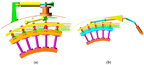
Figure 10.
Rigid–flexible coupling calculation models of two adjusting mechanisms with multiflexible bodies. (a) Paddle rod adjusting mechanism; (b) Push–pull rod adjusting mechanism.
3.4. Influence of Different Driving Modes on Adjusting Mechanism’s Different Guide Vane Angles
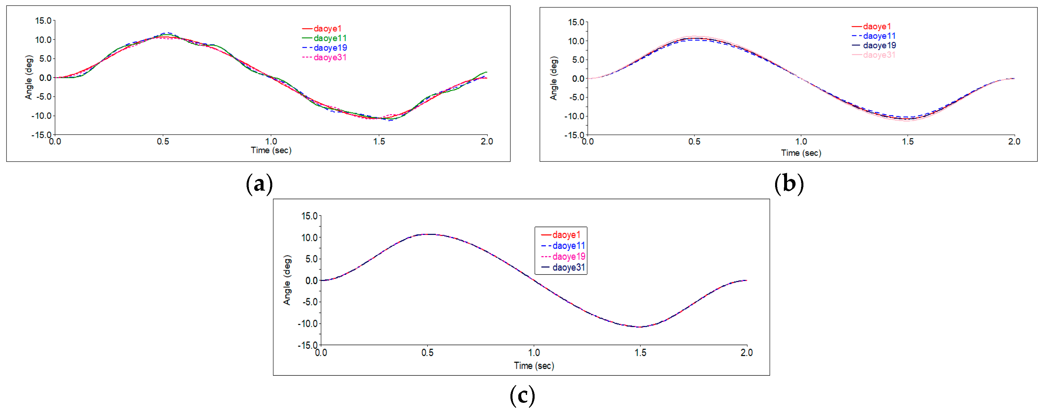
In our research group, another paper studies a rigid body calculation model at room temperature. The paper designs and researches the swing rod guide vane adjusting mechanism [30]. The effects of one driver, two drivers, and three drivers on different guide vanes angles are compared. Figure 11 shows the variation law of different guide vanes angles on variable geometry turbine adjusting mechanisms with three driving modes. It can be seen from Figure 11 that the angles among different guide vanes of the adjusting mechanisms with one driver and two drivers vary greatly. The angle differences can reach 2.3° and 1.9°, respectively. The angle changes among the three drivers’ adjusting mechanism’s different guide vanes are tiny. They are basically a curve track. The guide vanes’ angles are adjusted at the same turbine stage. This ensures the consistency of angle changes among different guide vanes.
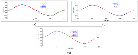
Figure 11.
Variation law of different guide vanes angles on variable geometry turbine adjusting mechanism with three driving modes. (a) One driver; (b) Two drivers; (c) Three drivers.
3.5. Analysis of Angle-Regulating Rule on Five Guide Vanes with Paddle Rod Adjusting Mechanism
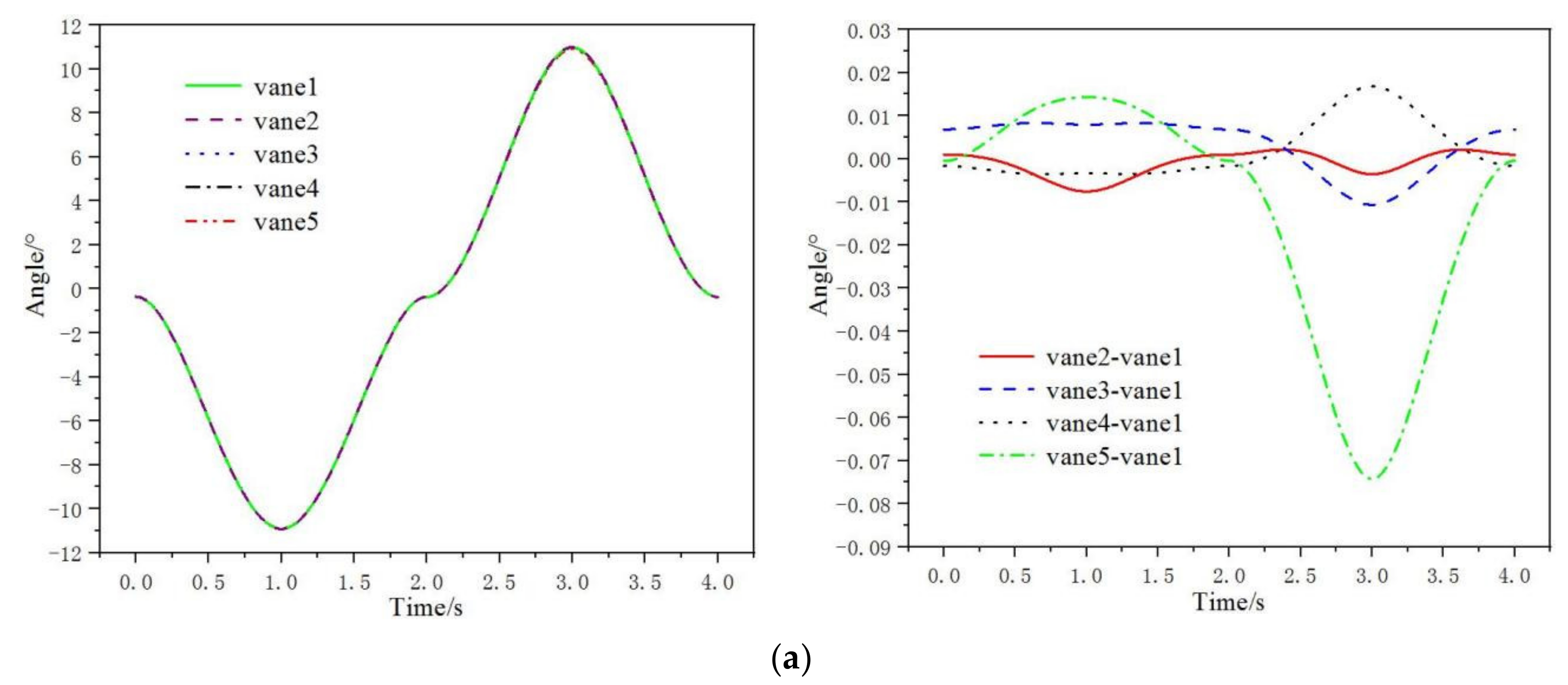
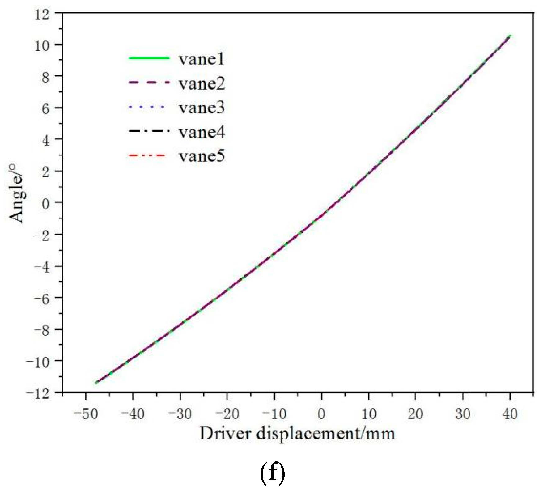
Figure 12 shows the angle-regulating rule of five guide vanes with a paddle rod adjusting mechanism. It can be seen from Figure 12 that the deflection angle ranges of the five guide vanes, respectively, are −10.9112°~+10.9763°, −10.9188°~+10.9799°, −10.9033°~+10.9692°, −10.9146°~+10.9967°, and −10.8969°~+10.9057° at 473.15K. The absolute values of deflection angle differences with the five guide vanes are 0.0036°, 0.0071°, 0.0204°, and 0.0706°, respectively. They are much less than the adjusting mechanism’s accuracy requirement of 0.5°. The deflection angle ranges of the five guide vanes, respectively, are −11.0973°~+10.6014°, −11.0947°~+10.5921°, −11.1128°~+10.612°, −11.0879°~+10.5835°, and −11.0776°~+10.5134° at 573.15K. The absolute values of the deflection angle differences with the five guide vanes are 0.0093°, 0.0106°, 0.0179°, and 0.088°, respectively. They are much less than the adjusting mechanism’s accuracy requirement of 0.5°. The deflection angle ranges of the five guide vanes, respectively, are −11.4003°~+10.5677°, −11.3587°~+10.5685°, −11.3678°~+10.5179°, −11.3728°~+10.5011°, and −11.3883°~+10.4838° at 673.15K. The absolute values of deflection angle differences with the five guide vanes are 0.0008°, 0.0498°, 0.0666°, and 0.0839° respectively. They are much less than the adjusting mechanism’s accuracy requirement of 0.5°. It can be seen from Figure 12d–f that the deflection angles of the five guide vanes are approximately linear with driver displacement, respectively, at 473.15K, 573.15K, and 673.15K. Furthermore, the curves of the five guide vanes are basically a curve track. The guide vanes’ angles are adjusted at the same turbine stage. This ensures the consistency of angle changes among different guide vanes.
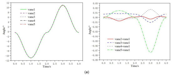
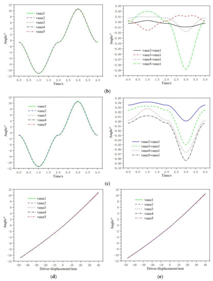
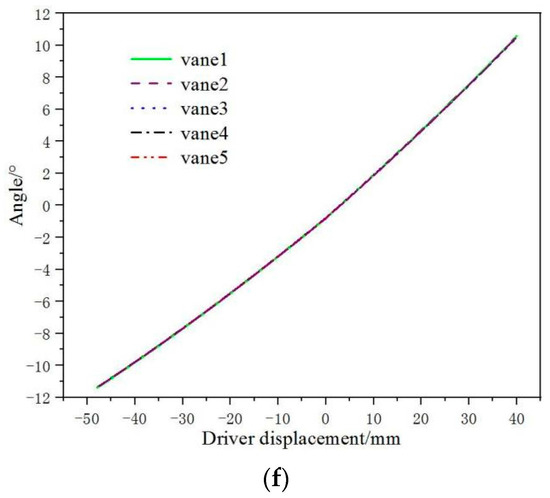
Figure 12.
Angle-regulating rule of five guide vanes with paddle rod adjusting mechanism. (a) Deflection angles and differences of five guide vanes at 473.15K; (b) Deflection angles and differences of five guide vanes at 573.15K; (c) Deflection angles and differences of five guide vanes at 673.15K; (d) Angle-regulating rule at 473.15 K; (e) Angle-regulating rule at 573.15K; (f) Angle-regulating rule at 673.15K.
3.6. Analysis of Angle-Regulating Rule on Five Guide Vanes with Push–Pull Rod Adjusting Mechanism
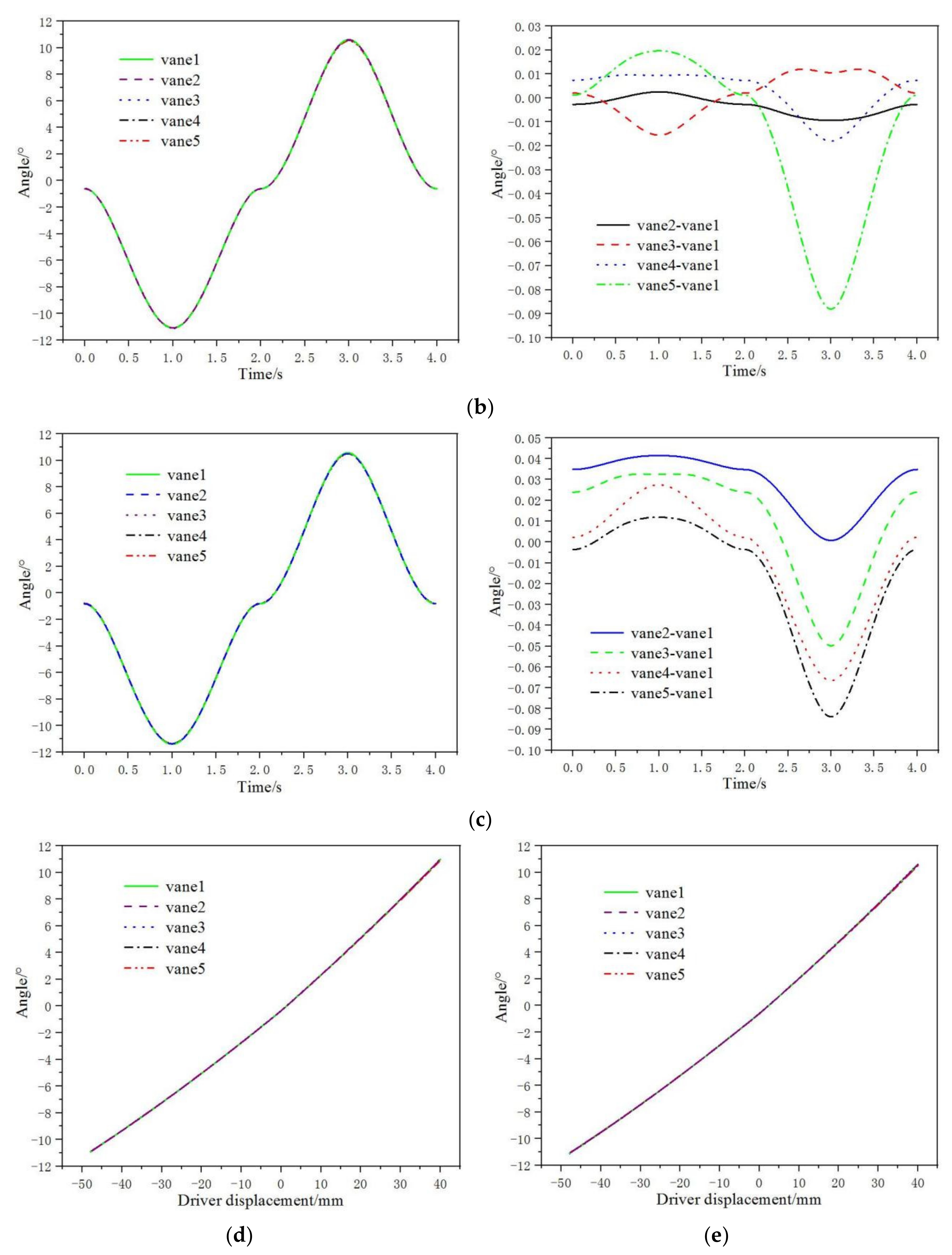
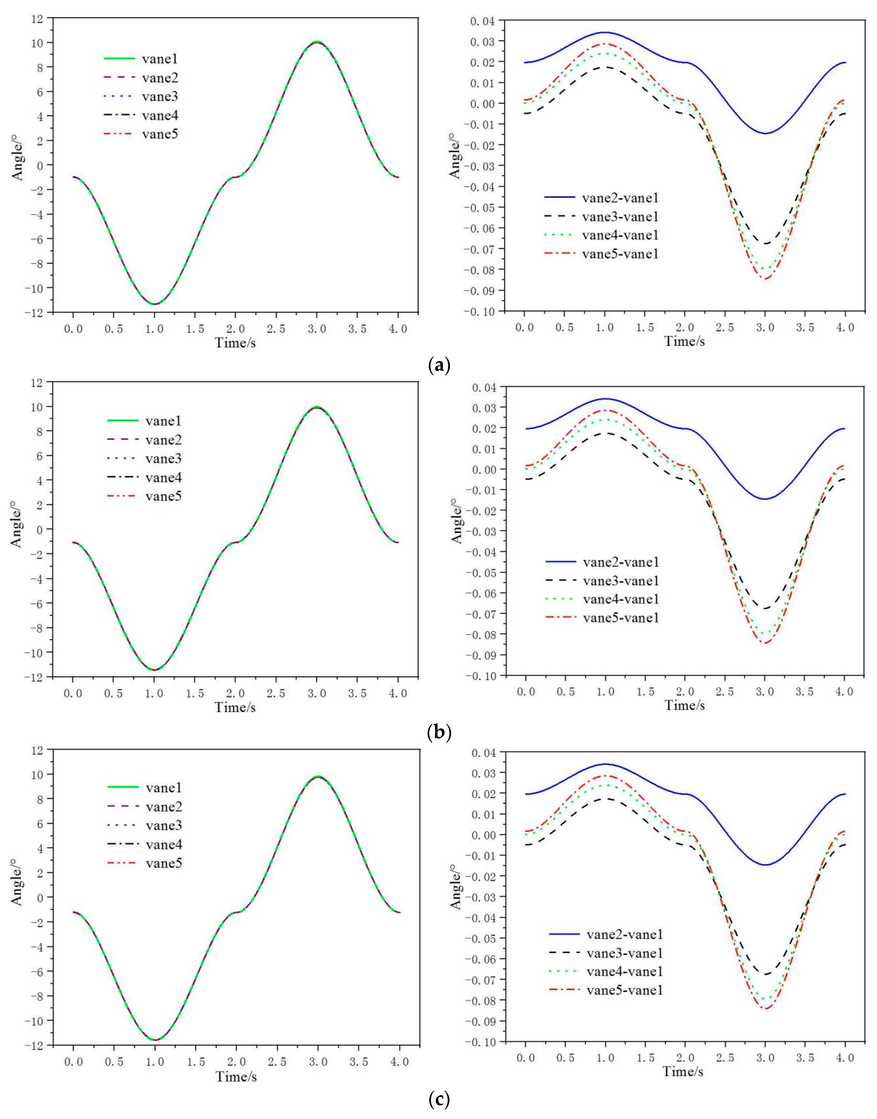
Figure 13 shows the angle-regulating rule of the five guide vanes with a push–pull rod adjusting mechanism. It can be seen from Figure 13 that the deflection angle ranges of the five guide vanes, respectively, are −11.351°~+10.0689°, −11.3169°~+10.0544°, −11.3336°~+10.0014°, −11.327°~+9.9892°, and −11.3224°~+9.9845° at 473.15K. The absolute values of deflection angle differences with the five guide vanes are 0.0145°, 0.0675°, 0.0797°, and 0.0844° respectively. They are much less than the adjusting mechanism’s accuracy requirement of 0.5°. The deflection angle ranges of the five guide vanes, respectively, are −11.4568°~+9.9694°, −11.4227°~+9.9548°, −11.4395°~+9.9019°, −11.4328°~+9.8897°, and −11.42838°~+9.8851° at 573.15K. The absolute values of deflection angle differences with the five guide vanes are 0.0146°, 0.0675°, 0.0797°, and 0.0843° respectively. They are much less than the adjusting mechanism’s accuracy requirement of 0.5°. The deflection angle ranges of the five guide vanes, respectively, are −11.6012°~+9.8234°, −11.5671°~+9.8088°, −11.5838°~+9.756°, −11.5773°~+9.744°, and −11.5727°~+9.7393° at 673.15K. The absolute values of deflection angle differences with the five guide vanes are 0.0146°, 0.0674°, 0.0794°, and 0.0841° respectively. They are much less than the adjusting mechanism’s accuracy requirement of 0.5°. It can be seen from Figure 13d–f that the deflection angles of the five guide vanes are approximately linear with driver displacement, respectively, at 473.15K, 573.15K, and 673.15K. Furthermore, the curves of the five guide vanes are basically a curve track. The guide vanes’ angles are adjusted at the same turbine stage. This ensures the consistency of angle changes among different guide vanes.
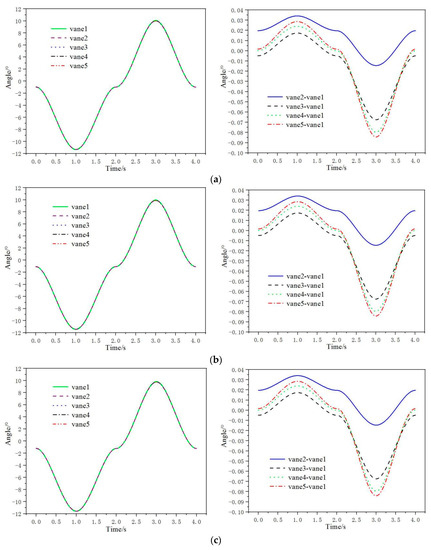
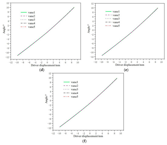
Figure 13.
Angle-regulating rule of five guide vanes with push–pull rod adjusting mechanism. (a) Deflection angles and differences of five guide vanes at 473.15K; (b) Deflection angles and differences of five guide vanes at 573.15K; (c) Deflection angles and differences of five guide vanes at 673.15K; (d) Angle-regulating rule at 473.15 K (e) Angle-regulating rule at 573.15K; (f) Angle-regulating rule at 673.15K.
3.7. Influence of Flexible Bodies and Thermal Deformations at Different Temperatures on the Angle-Regulating Rule of Two Adjusting Mechanisms’ Guide Vanes
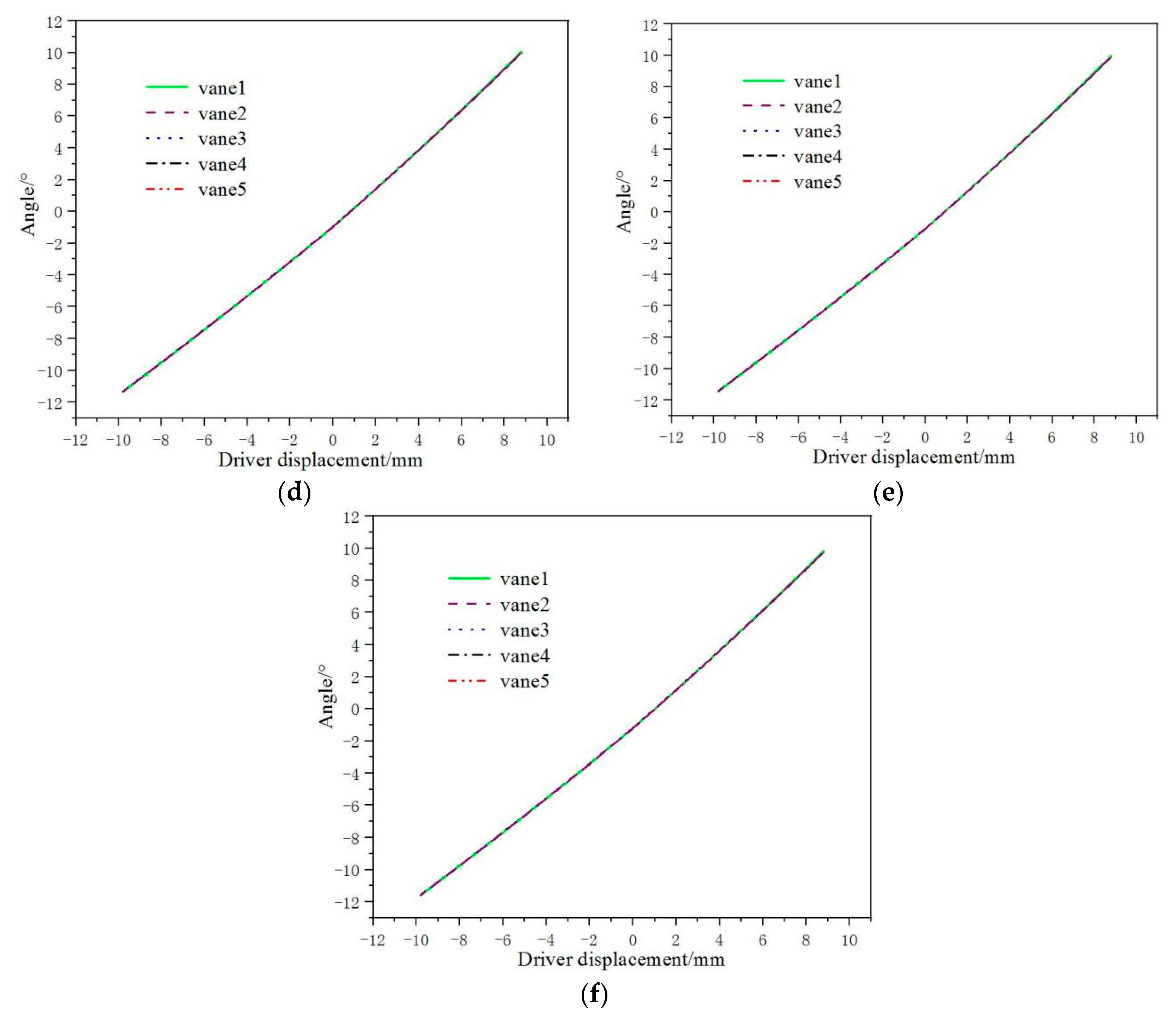
Figure 14 shows the influence of flexible bodies and thermal deformations at different temperatures on the angle-regulating rule of two adjusting mechanisms’ guide vanes. Figure 14a shows the deflection angle and difference of the guide vane of the paddle rod adjusting mechanism. At room temperature, the deflection angle of the guide vane of the rigid body model is 0° at 0 s. Driven by the driving device, the guide vane opening decreases to −10° when it is 1 s. At 2 s, the opening of the guide vane increases back to 0°. The guide vane opening increases to +10° at 3 s. At 4 s, the opening of the guide vane decreases back to 0° again. At the temperature conditions of 473.15K, 573.15K, and 673.15K, each component has high-temperature thermal deformation. The higher the temperature, the greater the thermal deformation displacement. At 473.15K, 573.15K, and 673.15K, the deflection angles of the guide vanes of the multiflexible bodies model deviate from that of the room temperature rigid body model. The higher the temperature, the greater the deviation. When the deflection angle of the guide vane of the room temperature rigid body model is 0°, the deflection angle deviations of the guide vanes of 473.15K, 573.15K, and 673.15K multiflexible bodies model are −0.35°, −0.61°, and −0.79°, respectively, compared with the room temperature rigid body model. When the deflection angle of the guide vane of the room temperature rigid body model is −10°, the deflection angle deviations of the guide vanes of 473.15K, 573.15K, and 673.15K multiflexible bodies model are −0.82°, −1°, and −1.28°, respectively, compared with the room temperature rigid body model. When the deflection angle of the guide vane of the room temperature rigid body model is +10°, the deflection angle deviations of the guide vanes of 473.15K, 573.15K, and 673.15K multiflexible bodies model are +0.97°, +0.6°, and +0.57°, respectively, compared with the room temperature rigid body model.
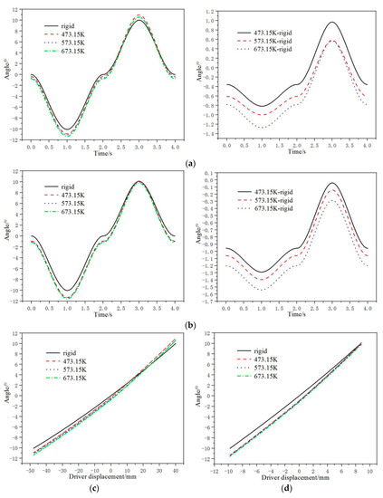
Figure 14.
Influence of flexible bodies and thermal deformations at different temperatures on angle-regulating rule of two adjusting mechanisms’ guide vanes. (a) Deflection angle and difference of guide vane of paddle rod adjusting mechanism; (b) Deflection angle and difference of guide vane of push–pull rod adjusting mechanism; (c) Paddle rod adjusting mechanism (d) Push–pull rod adjusting mechanism.
Figure 14b shows the deflection angle and difference of the guide vane of the push–pull rod adjusting mechanism. At room temperature, the deflection angle of the guide vane of the rigid body model is 0° at 0 s. Driven by the driving device, the guide vane opening decreases to −10° when it is 1 s. At 2 s, the opening of the guide vane increases back to 0°. The guide vane opening increases to +10° at 3 s. At 4 s, the opening of the guide vane decreases back to 0° again. At the temperature conditions of 473.15K, 573.15K, and 673.15K, each component has high-temperature thermal deformation. The higher the temperature, the greater the thermal deformation displacement. At 473.15K, 573.15K, and 673.15K, the deflection angles of the guide vanes of the multiflexible bodies model deviate from that of the room temperature rigid body model. The higher the temperature, the greater the deviation. When the deflection angle of the guide vane of the room temperature rigid body model is 0°, the deflection angle deviations of the guide vane of 473.15K, 573.15K, and 673.15K multiflexible bodies model are −0.95°, −1.06°, and −1.2°, respectively, compared with the room temperature rigid body model. When the deflection angle of the guide vane of the room temperature rigid body model is −10°, the deflection angle deviations of the guide vane of 473.15K, 573.15K, and 673.15K multiflexible bodies model are −1.29°, −1.38°, and −1.54°, respectively, compared with the room temperature rigid body model. When the deflection angle of the guide vane of the room temperature rigid body model is +10°, the deflection angle deviations of the guide vane of 473.15K, 573.15K, and 673.15K multiflexible bodies model are −0.05°, −0.14°, and −0.29°, respectively, compared with the room temperature rigid body model.
Figure 14c shows the relationship between the deflection angle of the guide vane of the paddle rod adjusting mechanism and the driver displacement. The deflection angle of the guide vane of the room temperature rigid body model is approximately linear with the driver displacement. When the driver displacement is −48 mm, the deflection angle of the guide vane is −10°. When the driver displacement is +40 mm, the deflection angle of the guide vane is +10°. The deflection angles of the guide vanes of 473.15K, 573.15K, and 673.15K multiflexible bodies models are also approximately linear with the driver displacement. When the driver displacement is −48 mm, the deflection angles of guide vanes of 473.15K, 573.15K, and 673.15K multiflexible bodies models are −10.82°, −11°, and −11.28° respectively. When the driver displacement is +40 mm, the deflection angles of guide vanes of 473.15K, 573.15K, and 673.15K multiflexible bodies models are +10.97°, +10.6°, and +10.57° respectively.
Figure 14d shows the relationship between the deflection angle of the guide vane of the push–pull rod adjusting mechanism and the driver displacement. The deflection angle of the guide vane of the room temperature rigid body model is approximately linear with the driver displacement. When the driver displacement is −9.8 mm, the deflection angle of the guide vane is −10°. When the driver displacement is +8.8 mm, the deflection angle of the guide vane is +10°. The deflection angles of the guide vanes of 473.15K, 573.15K, and 673.15K multiflexible bodies models are also approximately linear with the driver displacement. When the driver displacement is −9.8 mm, the deflection angles of guide vanes of 473.15K, 573.15K, and 673.15K multiflexible bodies models are −11.29°, −11.38°, and −11.54°, respectively. When the driver displacement is +8.8mm, the deflection angles of guide vanes of 473.15K, 573.15K, and 673.15K multiflexible bodies models are +9.95°, +9.86°, and +9.71°, respectively.
3.8. Evaluation and Comparison of Two Adjusting Mechanisms
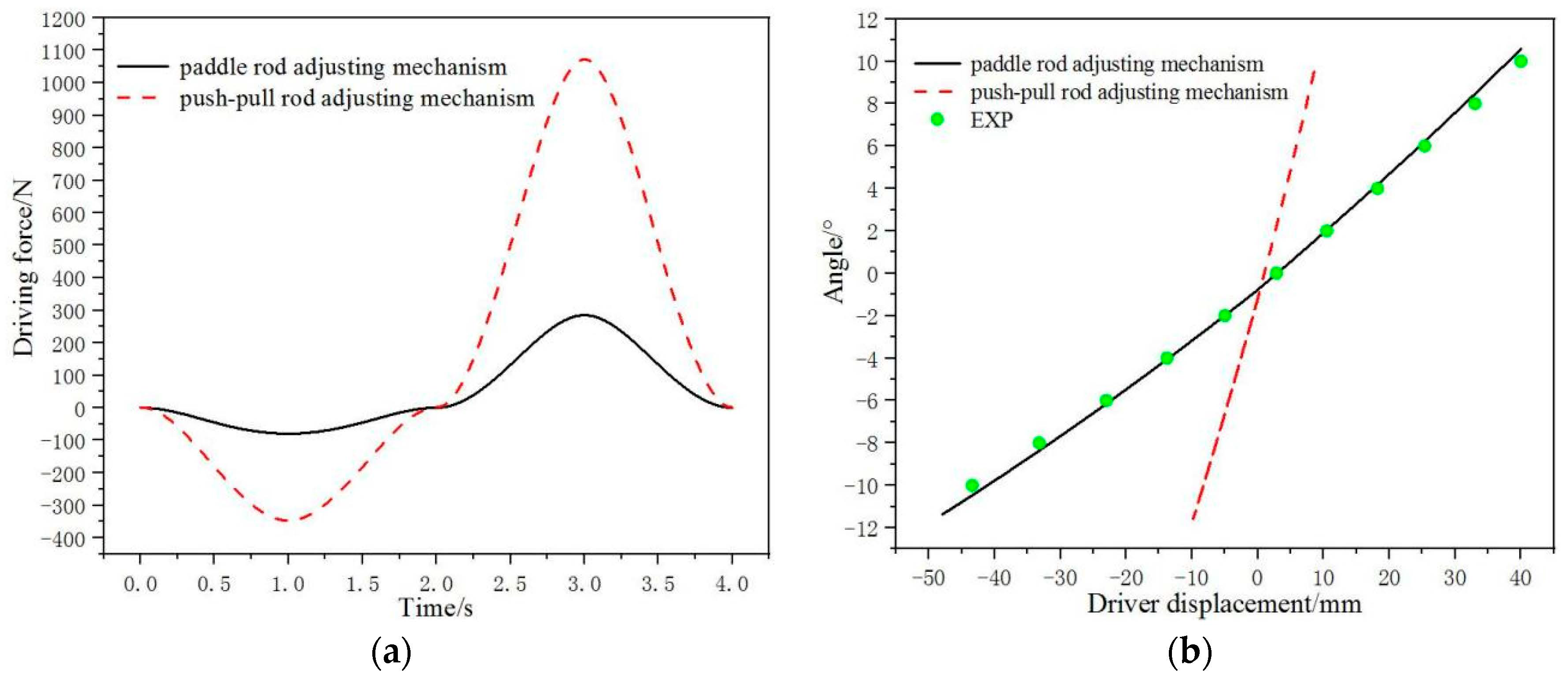
Figure 15 shows the variable geometry turbine of the variable cycle engine. Figure 16 shows the comparison of two adjusting mechanisms at 673.15K. Figure 16a shows the comparison of the driving forces of two adjusting mechanisms. The maximum driving force of the paddle rod adjusting mechanism is 284.88 N. The maximum driving force of the push–pull rod adjusting mechanism is 1072.27 N. In addition, in the whole adjustment process, the driving force of the paddle rod adjusting mechanism is smaller than that of the push–pull rod adjusting mechanism. Because the driving force is small, the deformation of the component is small in the process of movement. It is easier to realize the accurate adjustment of the guide vane angle.
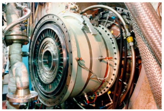
Figure 15.
Variable geometry turbine of variable cycle engine.
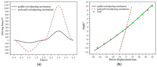
Figure 16.
Comparison of two adjusting mechanisms at 673.15K. (a) Driving force comparison; (b) Adjusting travel comparison.
Figure 16b shows the comparison of the adjustment travels of two adjusting mechanisms. When the deflection angle of the guide vane is −10°, the driver displacement of the paddle rod adjusting mechanism is −41 mm. Furthermore, the driver displacement of the push–pull rod adjusting mechanism is −8 mm. When the deflection angle of the guide vane is +10°, the driver displacement of the paddle rod adjusting mechanism is +38 mm. Furthermore, the driver displacement of the push–pull rod adjusting mechanism is +9 mm. During the adjustment process from −10° to +10°, the driving travel of the paddle rod adjusting mechanism is 79 mm. The driving travel of the push–pull rod adjusting mechanism is 17 mm. The larger the driving travel is, the more favorable it is for the guide vane angle to be accurately adjusted and maintained. At the same time, the institute provides necessary experimental data. The results of the joint computing system are in good agreement with the experimental data. The angle of the guide vane can be accurately adjusted by the paddle rod adjusting mechanism. It is superior to the push–pull rod adjusting mechanism.
4. Conclusions
The variable geometry turbine guide vane adjusting mechanism of a variable cycle engine is studied. CFD, ANSYS, and Adams are used to establish a joint simulation calculation system. The calculated results are compared with the experimental data provided by the institute. The following conclusions are obtained.
- The angles among different guide vanes of adjusting mechanisms with one driver and two drivers vary greatly. The angle differences can reach 2.3° and 1.9°, respectively. The angle changes among the three drivers’ adjusting mechanism’s different guide vanes are tiny. They are basically a curve track. The guide vanes’ angles are adjusted at the same turbine stage, ensuring ensures the consistency of angle changes among different guide vanes. The regulating rules of the five guide vanes angles of two adjusting mechanisms are basically the same curve track. The maximum difference in deflection angles of different guide vanes is 0.088°. It is much less than the adjusting mechanism’s accuracy requirement of 0.5°.
- At the temperature conditions of 473.15K, 573.15K, and 673.15K, each component has high-temperature thermal deformation. The higher the temperature is, the greater the thermal deformation displacement. At 473.15K, 573.15K, and 673.15K, the deflection angle of the guide vane of the multiflexible bodies model deviates from that of the room temperature rigid body model. The higher the temperature is, the greater the deviation. Before making the flexible bodies, the components conduct the thermal deformation analysis. In Figure 9 and Table 5, the higher the temperature, the greater the thermal deformation. The deformed components are made into flexible bodies. The rigid body model is a computational model at room temperature. The components of the rigid body model have no thermal deformations. So there is a deviation in the guide vane angle between the multiflexible bodies model and the rigid body model.
- At 673.15K, the maximum driving force of the paddle rod adjusting mechanism is 284.88N. The maximum driving force of the push–pull rod adjusting mechanism is 1072.27N. In addition, in the whole adjustment process, the driving force of the paddle rod adjusting mechanism is smaller than that of the push–pull rod adjusting mechanism. Because the driving force is small, the deformation of the component is small in the process of movement. It is easier to realize the accurate adjustment of the guide vane angle. During the adjustment process from −10° to +10°, the driving travel of the paddle rod adjusting mechanism is 79 mm. The driving travel of the push–pull rod adjusting mechanism is 17 mm. The larger the driving travel is, the more favorable it is for the guide vane angle to be accurately adjusted and maintained.
- The institute provides the necessary experimental data. The results of the joint computing system are in good agreement with the experimental data. The angle of the guide vane can be accurately adjusted by the paddle rod adjusting mechanism. It is superior to the push–pull rod adjusting mechanism. Furthermore, the production cost of the two adjusting mechanisms is too high. The experimental cycle is also very long. The computational work can result in significant cost savings. The computational work can provide and modify the necessary parameters at the beginning of the design, resulting in much convenience for the design work.
Author Contributions
Conceptualization, Y.Z. and X.W.; methodology, Y.Z. and L.Z.; software, Y.Z., H.B. and B.H.; validation, S.C. and J.L.; formal analysis, X.W. and L.Z.; investigation, H.B. and B.H.; resources, L.C.; data curation, Y.Z., S.C. and J.L.; writing—original draft preparation, Y.Z., X.W. and L.Z.; writing—review and editing, H.B. and B.H.; visualization, S.C. and J.L.; supervision, L.C.; project administration, L.C.; funding acquisition, L.C. All authors have read and agreed to the published version of the manuscript.
Funding
The research received no external funding.
Institutional Review Board Statement
Not applicable.
Informed Consent Statement
Not applicable.
Data Availability Statement
The data presented in this study are available on demand from the first author at (zhongyan524@163.com).
Acknowledgments
The authors gratefully acknowledge the support from the cooperation project between National Key Aero-engine Research Institute and Northeastern University (No. 2018JX03H002).
Conflicts of Interest
The authors declared no potential conflict of interest with respect to the research, authorship and/or publication of this article.
References
- Denton, J.D.; Dawes, W.N. Computational fluid dynamics for turbomachinery design. Proc. Inst. Mech. Eng. Part C J. Mech. Eng. Sci. 1998, 213, 107–124. [Google Scholar] [CrossRef]
- Wei, S.; Kun, Z. Design method for high Ma number counter rotating turbine blades. In Proceedings of the ASME Turbo Expo 2015: Turbine Technical Conference and Exposition, Montreal, QC, Canada, 15–19 June 2015. [Google Scholar]
- Boyce, M.P. Gas Turbine Engineering Handbook; Elsevier: Amsterdam, The Netherlands, 2011; pp. 841–842. [Google Scholar]
- Wirkowski, P. Modelling the characteristics of axial compressor of variable flow passage geometry, working in the gas turbine engine system. Pol. Marit. Res. 2007, 14, 27–32. [Google Scholar] [CrossRef]
- Hong, S.; Mugabi, J.; Jeong, J.-H. Numerical Study on Vortical Flow Structure and Performance Enhancement of Centrifugal Compressor Impeller. Appl. Sci. 2022, 12, 7755. [Google Scholar] [CrossRef]
- Han, F.; Wang, Z.; Mao, Y.; Tan, J.; Li, W. Flow Control of Radial Inlet Chamber and Downstream Effects on a Centrifugal Compressor Stage. Appl. Sci. 2021, 11, 2168. [Google Scholar] [CrossRef]
- Wang, Z.; Ren, X.; Zhu, W.; Li, X.; Gu, C. Numerical Investigation and Optimization of Variable Guide Vanes Adjustment in a Transonic Compressor. Energies 2023, 16, 567. [Google Scholar] [CrossRef]
- Romagnoli, A.; Martinez-Botas, R.; Rajoo, S. Steady state performance evaluation of variable geometry twin-entry turbine. Int. J. Heat Fluid Flow 2011, 32, 477–489. [Google Scholar] [CrossRef]
- Hadi, Y.; Ali, K.; Mohammad, A.; Behrad, K.; Hiwa, K. Aero-thermal redesign of a high pressure turbine nozzle guide vane. Propuls. Power Res. 2019, 8, 310–319. [Google Scholar]
- Zhang, L.; Cao, G.; Feng, K.; Jia, Y.; Zhang, Z. Improvement of Multi-Hole Airflow Impingement on Flow and Heat Transfer Characteristics Inside a Turbine Vane Cavity. Appl. Sci. 2021, 11, 9924. [Google Scholar] [CrossRef]
- Xu, T.; Shi, D.; Zhang, D.; Xie, Y. Flow and Heat Transfer Characteristics of the Turbine Blade Variable Cross-Section Internal Cooling Channel with Turning Vane. Appl. Sci. 2023, 13, 1446. [Google Scholar] [CrossRef]
- Jin, W.; Mao, Z.; Zhou, S.; Zhang, T.; Hu, Y.; Wu, Z. Research on Multi-Optimal Project of Outlet Guide Vanes of Nuclear Grade Axial Flow Fan Based on Sensitivity Analysis. Appl. Sci. 2022, 12, 3029. [Google Scholar] [CrossRef]
- Xin, J.; Liu, X.; Malik, A.; Liu, H.; Zhao, L.; Kong, X. Investigation of the Flow Field and Aerodynamic Load on Impellers under Guide Vanes with a Self-Induced Slot in Compressor Radial Inlet. Appl. Sci. 2022, 12, 5179. [Google Scholar] [CrossRef]
- José, R.S.; Andrés, O.T.; Juan, A.L.; Natalia, H. Numerical evaluation in a scaled rotor-less nozzle vaned radial turbine model under variable geometry conditions. Appl. Sci. 2022, 12, 7254. [Google Scholar]
- Meng, F.; Li, Y.; Pei, J. Energy Characteristics of Full Tubular Pump Device with Different Backflow Clearances Based on Entropy Production. Appl. Sci. 2021, 11, 3376. [Google Scholar] [CrossRef]
- Yi, X.; Wang, Z.; Liu, S.; Hou, X.; Tang, Q. An Accelerated Degradation Durability Evaluation Model for the Turbine Impeller of a Turbine Based on a Genetic Algorithms Back-Propagation Neural Network. Appl. Sci. 2022, 12, 9302. [Google Scholar] [CrossRef]
- Liang, D.; Jin, D.; Gui, X. Investigation of Seal Cavity Leakage Flow Effect on Multistage Axial Compressor Aerodynamic Performance with a Circumferentially Averaged Method. Appl. Sci. 2021, 11, 3937. [Google Scholar] [CrossRef]
- Szymon, F.; Maciej, C.; Marian, G. Variable geometry in miniature gas turbine for improved performance and reduced environmental impact. Energies 2020, 13, 5230. [Google Scholar]
- Dariusz, K.; Paweł, M.; Andrzej, T. Numerical simulation of two-stage variable geometry turbine. Energies 2021, 14, 5349. [Google Scholar]
- Krzysztof, S.; Damian, O.; Piotr, R.; Emil, M. Numerical investigations of the savonius turbine with deformable blades. Energies 2020, 13, 3717. [Google Scholar]
- Čantrak, D.S.; Janković, N.Z. Turbulence structure and dynamics investigation of turbulent swirl flow in pipe using high-speed stereo PIV data. Energies 2022, 15, 5417. [Google Scholar]
- Li, D.; Qiu, L.; Tao, K.; Zhu, J. Artificial intelligence aided design of film cooling scheme on turbine guide vane. Propuls. Power Res. 2020, 9, 344–354. [Google Scholar] [CrossRef]
- Yang, H.; He, Q.; Huang, X.; Yang, M.; Bi, H.; Wang, Z. Experimental and Numerical Investigation of Rotor–Stator Interaction in a Large Prototype Pump–Turbine in Turbine Mode. Energies 2022, 15, 5523. [Google Scholar] [CrossRef]
- Li, Y.; Song, Y.; Xia, S.; Li, Q. Influence of Guide Vane Slope on Axial-Flow Hydraulic Performance and Internal Flow Characteristics. Energies 2022, 15, 6103. [Google Scholar] [CrossRef]
- Yang, F.; Jiang, D.; Wang, T.; Chang, P.; Liu, C.; Liu, D. Investigation into the Influence of Division Pier on the Internal Flow and Pulsation in the Outlet Conduit of an Axial-Flow Pump. Appl. Sci. 2021, 11, 6774. [Google Scholar] [CrossRef]
- Jesline, J.; Mehrdad, R.; Michel, J.C. Hydraulic performance of a francis turbine with a variable draft tube guide vane system to mitigate pressure pulsations. Energies 2022, 15, 6542. [Google Scholar]
- Vijay Kumar, M.; Subba Reddy, T.; Sarala, P.; Varma, P.S.; Chandra Sekhar, O.; Babqi, A.; Alharbi, Y.; Alamri, B.; Reddy, C.R. Experimental investigation and performance characteristics of francis turbine with different guide vane openings in hydro distributed generation power plants. Energies 2022, 15, 6798. [Google Scholar] [CrossRef]
- Kaddour, T.; Adel, G. Simulation and analysis of vane-blade interaction in a two-stage high-pressure axial turbine. Energy 2019, 172, 1291–1311. [Google Scholar]
- Chen, X.; Chu, W.; Wang, G.; Yan, S.; Shen, Z.; Guo, Z. Effect of span range of variable-camber inlet guide vane in an axial compressor. Aerosp. Sci. Technol. 2021, 116, 106836. [Google Scholar] [CrossRef]
- Lv, M.; Chen, L.; Zhong, Y.; Wang, L. Design and research of swing rod guide vane adjusting mechanism. Modul. Mach. Tool Autom. Manuf. Tech. 2020, 4, 28–32. [Google Scholar]


Disclaimer/Publisher’s Note: The statements, opinions and data contained in all publications are solely those of the individual author(s) and contributor(s) and not of MDPI and/or the editor(s). MDPI and/or the editor(s) disclaim responsibility for any injury to people or property resulting from any ideas, methods, instructions or products referred to in the content. |
© 2023 by the authors. Licensee MDPI, Basel, Switzerland. This article is an open access article distributed under the terms and conditions of the Creative Commons Attribution (CC BY) license (https://creativecommons.org/licenses/by/4.0/).