Article

Activity Evaluation Methodology for the Disposed Medical Linear Accelerators

1
Department of Radiation Oncology, Yonsei Cancer Center, Heavy Ion Therapy Research Institute, Yonsei University College of Medicine, Seoul 03722, Republic of Korea
2
Medical Physics and Biomedical Engineering Lab (MPBEL), Yonsei University College of Medicine, Seoul 03722, Republic of Korea
3
Department of Accelerator Science, Korea University, Sejong 30015, Republic of Korea
4
Research Team of Radiological Physics & Engineering, Korea Institute of Radiological & Medical Sciences, Seoul 01812, Republic of Korea
5
Department of Radiation Oncology, Korea Institute of Radiological & Medical Sciences, Seoul 01812, Republic of Korea
6
R&D Institute, Sae-An Enertech Corp, Daejeon 34016, Republic of Korea
7
Oncosoft Inc., Seoul 03787, Republic of Korea
*
Authors to whom correspondence should be addressed.
These authors contributed equally to this work.
Appl. Sci. 2023, 13(1), 528; https://doi.org/10.3390/app13010528
Submission received: 22 November 2022 / Revised: 23 December 2022 / Accepted: 27 December 2022 / Published: 30 December 2022

Abstract

:
For the medical linear accelerators (linac) that utilize more than 10 MV of photon energy, components inside the linac head become radioactivate during the 10–15-year operating cycle. Prior to disposal, radioactive waste must be evaluated for activity, and the same procedure should be followed for medical linacs. In the Republic of Korea, regulation and methodology for the radioactivity evaluation for the medical linac is not established yet. In this study, we employed gamma spectroscopy and a survey meter for evaluating the radioactivity of medical linac components. The components of the Siemens linac considered in this study were classified after decommissioning, and dose rates were measured to up to a 5 cm distance from the component surfaces by using a survey meter. Radionuclides from components were detected using an in situ HPGe detector. Based on the type of radionuclides and dose rate, we estimated the radioactivity of the components. We studied the feasibility of the methodology for disposing of radioactive components by using the in situ HPGe detector.

1. Introduction

Radioactive waste management and disposal are regulated to reduce human exposure to radioactivity [1,2]. The waste is treated and disposed of according to its radioactivity level classifications. In the Republic of Korea, medical linear accelerators (linacs) are decommissioned and disposed of by linac manufacturing agencies [3]. However, as the legal regulations and disposal protocols are not established for the disposal of medical linacs, the agencies do not proceed with the measurement of the radioactivity; they measure the dose rates of the individual components by using a survey meter. The agencies classify the components based on the natural background dose rate; waste with a higher dose rate than that of the background is stored and managed for a certain period. Some hospitals dispose of the radioactive waste as regular scrap metal because of the absence of an established protocol.
Medical linacs are disposed of after an average of 10–15 years of usage. The internal components of the linac head become radioactive through neutron activation. Radionuclide identification and radioactivity evaluation must adhere to the clearance levels stipulated in the Nuclear Safety Act, Article 107, Paragraph 1, prior to the decommissioning of the disposal of linac components [1,4,5]. As the components of the linac head vary in shape and size and are manufactured using manufacture-specific compounds, identifying the component- and manufacturer-specific radionuclide information is important. However, as the majority of the components are composed of scrap metal, either melting or cutting them is impractical. Moreover, certified reference material (CRM) is used to correct the activity; however, its density is similar to that of water (1 g/cm3), and it is limited to correcting the radioactivity of the metal.
Following the work by Amgarou et al., various in situ measurement techniques and detectors have been proposed for radiological characterization in radiological installations under decommissioning and dismantling processes [6]. For waste studies, gamma ( γ )-ray spectrometry is the recommended technique as the non-destructive assay. The NaI(Tl) detector does not require cooling and is more cost effective and easier to handle in small sizes compared to the HPGe detector [7]. However, among the γ -spectrometry detectors, the high-purity germanium (HPGe) detector has the best energy resolution (~0.15% @ 662 keV) compared with other detectors, such as NaI(Tl) detector (~7% @ 662 keV), BGO (Bi4Ge3O12) detector (~10% @ 662 keV), LaBr3(Ce) detector (~3% @ 662 keV), and CZT detector (~2.5% @ 662 keV) [6,7]. For the radioactivity evaluation of each component mixed with various materials, the use of an HPGe detector with high sensitivity and high resolution [8,9,10] is considered appropriate.
In this study, we developed a method for initial radioactivity evaluation by using a portable HPGe detector at the decommissioning site and studied the feasibility of the proposed method. After decommissioning the linac, its components were classified, and the radionuclides were identified using in situ gamma spectroscopy. We conducted the spectroscopy using a portable HPGe detector and an in situ objective counting system (ISOCSTM, Mirion Technologies (Canberra) Inc., Meriden, CT, USA) [11]. After the reference radionuclides were acquired, we estimated the activity (Bq/g) using the dose rate measured by the survey meter.

2. Materials and Methods

2.1. Sourcing a Disposed Medical Linac

A Siemens Oncor Expression medical linac was shut down for disposal in August 2021. The linac was collected following its disposal schedule in collaboration with a medical institution. The linac was installed in 2007 and disposed of after 14 years of operation. It utilized 6 and 15 MV photon energies in a 50:50 ratio and was used in the treatment of approximately 50 patients per day. Further, the average portions of the linac operation for three-dimensional conformal radiotherapy and intensity-modulated radiotherapy techniques were 30–40% and 60–70%, respectively. The primary radiation workload ranged from 343 to 516 Gy/week (average: 394 Gy/week).
Head components of Siemens medical linac are composed of various parts and materials (Figure 1, Table 2). In the order starting from the top, the head of the linac is composed of bending magnet, target, primary collimator, ionization chamber, mirror, Y jaw, and multileaf collimator (MLC). There are also two primary collimators for different energy: 10 and 15 MV photon beam treatment.

2.2. Proposing an Activity Evaluation Methodology for Linac

After the medical Siemens linac was collected from the medical institution for decommissioning, the head part of the linac was dismantled. Its head components were separated and classified for the measurements. Further, the dose rates and gamma spectrum were measured three days after the linac shutdown for decommissioning. The initial radioactivity was measured using a survey meter and evaluated using an in situ HPGe detector at the decommissioning site. Figure 2 depicts the proposed procedure for the activity evaluation methodology for the disposed medical linac.

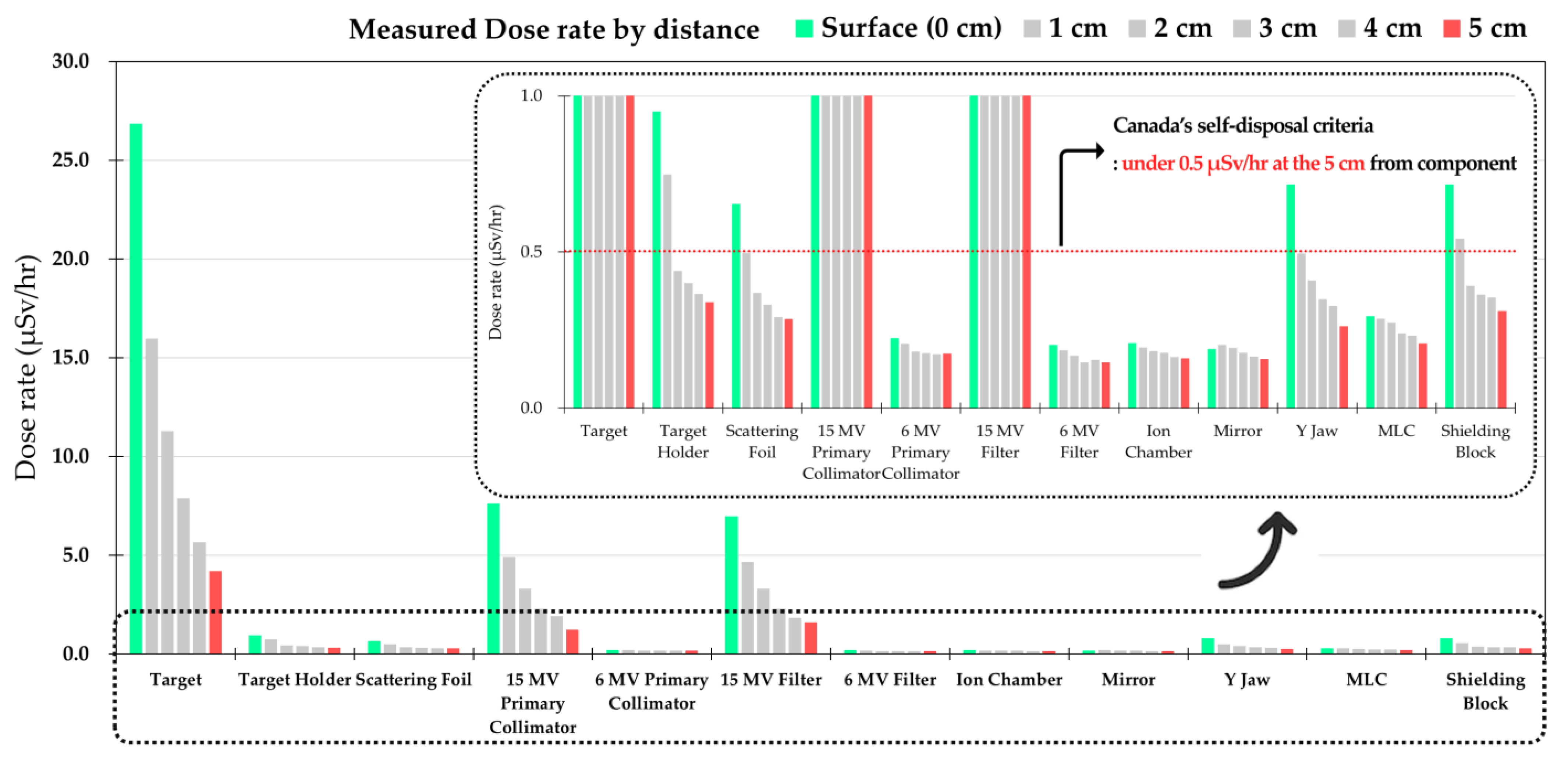
2.2.1. Dose Rate Measurements using a Survey Meter

The head of the decommissioned Siemens linac was disassembled, and the components were classified following the treatment beam line (Figure 3a). After classifying the components, a survey meter (FH-40 G-L10, Thermo Scientific, Waltham, MA, USA) was used to measure the dose rate (Figure 3b). The environmental background dose rate was measured for 5 min. The components exhibiting dose rates greater than those of the background dose rates were primarily classified. The component dose rates were measured by holding a survey meter at distances from 0 to 5 cm, at 1 cm intervals. The dose rates were measured five times, and the average value was calculated. Further, the dose rates after five weeks post-decommissioning were measured.

2.2.2. Gamma Spectroscopy using an In Situ HPGe Detector

The gamma spectra were obtained for the previously classified linac head components using a survey meter. The in situ HPGe detectors (GC2018, Mirion Technologies (Canberra) Inc., Meriden, CT, USA) were linked to the analysis software, and the gamma spectra were obtained after applying a 3000 V high voltage [12]. Table 1 lists the in situ HPGe detector model, detection efficiency, energy resolution, and analysis software.
The energy was calibrated prior to the experiment to match the spectrum channel and gamma energy using 152Eu standard source. The channel energy calibration accuracy was checked using 60Co standard source just before acquiring the spectrum. The distance between the examined components and the detector was adjusted so that the dead time was below 3%. The positions of the components were adjusted to match their centers with the centers of the detectors. The spectra were measured for 1800 s for each component.
The spectra were qualitatively analyzed to identify the nuclides that were activated while excluding naturally occurring radionuclides. The spectra were analyzed using Genie 2000 Gamma analysis software (Mirion Technologies (Canberra), Meriden, CT, USA) [13]. The measured parts were modeled using ISOCSTM software by approximating them as sources. The geometries of the measured targets were simulated considering the shape of the actual components such as a cylinder, box, dotted circle, and plane. The component characteristics were analyzed by inputting their distances from the detector, the primary component materials, their densities, and masses [14,15,16].

3. Results

3.1. Component Dose Rate Measurements

The material, mass, and volume information of the linac components are listed in Table 2. The measured dose rates for the target, 15 MV primary collimator, and 15 MV flattening filter were above 6 µSV/h because of the effect of the frequent collisions with high-energy electrons and photons. Dose rates lower than 1 µSV/h were measured from the lead block, upper Y jaw, scattering foil, ionization chamber, MLC, 6 MV flattening filter, and the mirror components.
The dose rates for each component were measured on the day of disposal (Table 3) and after five weeks (Table 4). The dose rates were measured using a survey meter held at the surface at 5 cm distances with 1 cm intervals. As shown in Figure 4, the dose rate decreased logarithmically with increasing measurement distance. The components that exhibit 0.5 µSV/h or lower dose rates at 5 cm can be disposed of under Canadian law regarding the clearance level for disposal/recycling/reusing the activated medical accelerator components [17]. Following the Canadian guideline, the target, flattening filter, and primary collimator components were not allowed to be discarded on the day of disposal or for five weeks after.

3.2. Gamma Spectroscopy of the Components

The gamma spectra of the Siemens linac components were acquired using the Canberra in situ HPGe detector. As shown in Figure 5, we simulated each component with a geometry that was as reflected the real dimension and shape as possible, considering the design drawing of the linac and the real measured dimensions of the part, and obtained the efficiency coefficient of each component.
Table 5 lists the radionuclides generated from the radioactivity of the components. The naturally occurring radionuclides and the radionuclides that exhibited lower activity than the minimum detectable activity (MDA) were also excluded. Approximately twenty different radionuclides, including 57Co, 51Cr, 54Mn, 57Ni, 58Co, 60Co, 65Zn, 99Mo, 181W, 187W, 196Au, and 198Au, were identified following Siemens linac component gamma spectroscopy. Figure 6 is the spectra of the target and 15 MV primary collimator. For target which composed of gold, copper, and tungsten materials, the energy peaks of 196Au, 198Au, 57Co, 60Co, 54Mn, 99Mo, and 187W were distinguished as shown in Figure 6a. The energy peaks of 57Co, 58Co, 60Co, 54Mn, 99Mo, 57Ni, and 187W were identified for the 15 MV primary collimator, as shown in Figure 6b.

4. Discussion

In this study, we developed an in situ HPGe detector and survey meter-based methodology for medical linac component radionuclide identification and radioactivity level detection. Because of the high cost of the HPGe detector, it is not easy to place an HPGe detector with analyzing software in every medical institution. Moreover, it is remarkably difficult for users to analyze metal-based radioactive waste. However, we can simply estimate the activity (Bq/g) of the component with the information on the radionuclide and the dose rate. In our methodology, we acquired the information on the radionuclides using the ISOCSTM program without considering the uncertainty due to the difference in density. The components in a medical linac head vary in their constituent material, density, size, and shape. The feasibility of the methodology was studied, targeting a discarded medical Siemens linac. The radioactivity-derived radionuclides were identified, and the dose rate-based radioactivity levels were determined.
The efficiency calibration of the HPGe detector generally uses the CRM of the 1 g/cm3 density. As the linac was predominantly composed of metals, the uncertainty can be increased because of the different densities of CRM [18,19]. It is difficult to acquire a metal-based CRM in reality. The components to be measured need to be pre-processed to match their volume and shape to the CRM. Preparing adequate samples was challenging as the preprocessing involved melting and cutting the predominantly metallic components. As a result, in situ HPGe detector-based measurements for medical linac radioactive waste that could not be processed further were feasible. We employed ISOCSTM software for the geometry and density corrections, and the radionuclides were identified for each component.
The Japanese guideline suggests correcting the survey meter-measured dose rates with weight and radioactivity conversion factors for calculating the radioactivity (in Bq) [20]. The dose rate-based radioactivity values were calculated for the Siemens linac components using the Japanese radioactivated material management methodology (Table 6). The radionuclides and radioactivity (Qi = H × Ki × F) were determined using the measured surface dose rate (H), component weight (F), conversion factor per material, and radionuclide (Ki). The radioactivity from the decommissioning day and five weeks post-decommissioning were compared. Most components exhibited radioactivity higher than that of the clearance limit according to the National Nuclear Safety Act. In the case of the 6 MV primary collimator and the ion chamber, the result exceeded the clearance level for self-disposal even though a dose rate of approximately 0.1 uSv/h higher than the background dose rate was measured. When the dose rate is inversely calculated based on the radioactivity value at the clearance allowance limit for self-disposal, self-disposal was judged to be possible only when the dose rate is at the background level. According to the Canadian regulatory limit, all the activities of the components, except the target, 15 MV linear collimator, and 15 MV flattening filter were allowed for disposal as their activities were under the clearance level [17]. The Japanese regulations are more stringent than the Canadian regulations in clearing the radioactivated medical components and require that the component radioactivity be comparable to the natural background radioactivity prior to clearance, despite the material and size-based differences.

5. Conclusions

We proposed a simple methodology for evaluating radioactivity in radioactive materials generated during medical linac disposal. Using an in situ HPGe detector and survey meter, we identified the radionuclides of each component, and radioactivity was calculated. According to Japanese regulations, when the dose rates for the components are similar to the dose rate of the background, it is allowed to be self-disposed. Based on Canadian regulations, we can expect that all the components except the target, 15 MV collimator, and 15 MV filter can be cleared on the decommissioning day.
The proposed method will be potentially beneficial as a general framework for establishing the linac radioactivity evaluation and safety management standards. Furthermore, it is expected that it can also be applied to the radiation evaluation field of linear accelerators and high-energy particle accelerators from other manufacturers.

Author Contributions

Conceptualization, N.H.K. and S.H.C.; Data curation, Y.J.J.; Formal analysis, Y.J.J.; Funding acquisition, D.W.K. and S.H.C.; Investigation, K.B.K.; Methodology, N.H.K. and J.H.Y.; Project administration, S.H.C.; Supervision, J.K. and D.W.K.; Validation, K.B.K. and J.K.; Writing—original draft, N.H.K.; Writing—review and editing, S.H.C. All authors have read and agreed to the published version of the manuscript.

Funding

The Nuclear Safety Research Program supported this work through the Korea Foundation of Nuclear Safety (KoFONS) using financial resources granted by the Nuclear Safety and Security Commission (NSSC) of the Republic of Korea (No. 2003013, No. 2205013) and the National Research Foundation of Korea (NRF) grant funded by the Korean government (No. 2020M2D9A3094170, RS-2022-00144201).

Institutional Review Board Statement

Not applicable.

Informed Consent Statement

Not applicable.

Data Availability Statement

Not applicable.

Conflicts of Interest

The authors declare no conflict of interest.

References

  1. Radioactive Waste Safety Division, Nuclear Safety and Security Commission. Nuclear Safety and Security Commission Notification No. 2020-6, Regulations on Radioactive Waste Classification and Clearance Standards (Implementation and Revision in 2020.05.26); Radioactive Waste Safety Division, Nuclear Safety and Security Commission: Seoul, Republic of Korea, 2020. [Google Scholar]
  2. MOTIE. Radioactive Waste Control Act No. 15082 (Implementation and Revision in 2017.11.28); Ministry of Trade Industry and Energy (MOTIE): Seoul, Republic of Korea, 2017.
  3. Kwon, N.H.; Jang, Y.J.; Kim, D.W.; Shin, D.O.; Kim, K.B.; Kim, J.S.; Choi, S.H. Trend Analysis on Korean and International Management for Activated Material Waste from Medical Linear Accelerator. Prog. Med. Phys. 2020, 31, 194–204. [Google Scholar] [CrossRef]
  4. Hong, Y.; Jang, W.; Kim, J.; Lee, W. A Case Study of Procedures and Methods for Self-Disposal of Radioactive Wastes Generated after Nuclear Research and Development. J. Radiat. Ind. 2021, 15, 85–91. [Google Scholar]
  5. Pérot, B.; Jallu, F.; Passard, C.; Gueton, O.; Allinei, P.-G.; Loubet, L.; Estre, N.; Simon, E.; Carasco, C.; Roure, C.; et al. The characterization of radioactive waste: A critical review of techniques implemented or under development at CEA, France. EPJ Nucl. Sci. Technol. 2018, 4, 2018. [Google Scholar] [CrossRef]
  6. Amgarou, K.; Aspe, F.; Idoeta, R.; Herranz, M. Recommendations for the selection of in situ measurement techniques for radiological characterization in nuclear/radiological installations under decommissioning and dismantling processes. Prog. Nucl. Energy 2021, 137, 103761. [Google Scholar] [CrossRef]
  7. Hossain, I.; Sharip, N.; Viswanathan, K.K. Efficiency and resolution of HPGe and NaI (Tl) detectors using gamma-ray spectroscopy. Sci. Res. Essays 2012, 7, 86–89. [Google Scholar] [CrossRef]
  8. Vichi, S.; Dean, D.; Ricci, S.; Zagni, F.; Berardi, P.; Mostacci, D. Activation study of a 15MeV LINAC via Monte Carlo simulations. Radiat. Phys. Chem. 2020, 172, 108758. [Google Scholar] [CrossRef]
  9. Ajaj, F.A.A.; Ghassal, N.M.H. An MCNP-based model of a medical linear accelerator x-ray photon beam. Australas. Phys. Eng. Sci. Med. 2003, 26, 140–144. [Google Scholar] [CrossRef] [PubMed]
  10. Jang, Y.-J.; Kwon, N.H.; Park, S.H.; Choi, Y.; Yu, H.; Kim, K.B.; Kim, D.W.; Choi, S.H. Activation evaluation of Siemens linear accelerator using Monte Carlo simulation. J. Korean Phys. Soc. 2022, 81, 1107–1114. [Google Scholar] [CrossRef]
  11. Mirion Technologies (Canberra), Inc., ISOCS™ Calibration Software. Available online: https://www.mirion.com/products/s573-isocs-calibration-software (accessed on 10 October 2022).
  12. Mirion Technologies (Canberra), Inc., GC2018 Germanium Detectors Software. Available online: https://www.mirion.com/products/germanium-detectors (accessed on 17 July 2022).
  13. Mirion Technologies (Canberra), Inc., Genie 2000 Software. Available online: https://www.mirion.com/products/genie-2000-basic-spectroscopy-software (accessed on 17 July 2022).
  14. Jäderström, H.; Lester, R.; Bronson, F.; Venkataraman, R.; Atrashkevich, V. Validation of general purpose mathematical efficiency modeling with ISOCS—15579. In Proceedings of the WM2015: Annual Waste Management Symposium, Phoenix, AZ, USA, 15–19 March 2015. [Google Scholar]
  15. Jeong, H.C.; Jeong, S.Y. Assessment of the Radiological Inventory for the Reactor at Kori NPP Using In-Situ Measurement Technology. J. Nucl. Fuel Cycle Waste Technol. 2014, 12, 171–178. [Google Scholar] [CrossRef]
  16. Leong, L.S.; Beaujoin, J.; Tischenbach, E.; Chard, P. Fast, Accurate and Simple Modelling of Complex Objects with Innovative ISOCS-Based Service Tool for Cost-Effective Waste Management (IAEA-CN--294); International Atomic Energy Agency (IAEA): Vienna, Austria, 2021. [Google Scholar]
  17. Canadian Nuclear Safety Commission. Conditional Clearance Levels for the Disposal, Recycling and Reuse of Activated Medical Accelerator Components. 2018. Available online: http://nuclearsafety.gc.ca/eng/nuclear-substances/licensing-class-II-nuclear-facilities-and-prescribed-equipment/information-class-II-licensed-facilities/conditional-clearance-levels-activated-medical-accelerator-components.cfm?pedisable=true (accessed on 15 October 2022).
  18. Seo, B.K.; Lee, K.Y.; Yoon, Y.Y.; Jung, K.J.; Oh, W.Z.; Lee, K.W. Variation of the Detection Efficiency of a HPGe Detector with the Density of the Sample in the Radioactivity Analysis. Anal. Sci. Technol. 2005, 18, 59–65. [Google Scholar]
  19. Barrera, M.; Casas-Ruiz, M.; Alonso, J.J.; Vidal, J. Precise determination of HPGe detector efficiency for gamma spectrometry measurements of environmental samples with variable geometry and density. Nukleonika 2017, 62, 47–59. [Google Scholar] [CrossRef] [Green Version]
  20. Joint Working Group of Medical Societies Related to Clearance and Radiotherapy in Japan. Society Standard for Radiotherapy Management in Radiotherapy Equipment. 2014.
Figure 1. Components of the Siemens linac head.
Applsci 13 00528 g001
Figure 2. Procedure of the activity evaluation methodology for the disposed medical linac.
Applsci 13 00528 g002
Figure 3. (a) Classifying the components of the Siemens linac head and (b) survey meter for measuring the dose rate.
Applsci 13 00528 g003
Figure 4. Dose rate of the component by distance: 0 cm to 5 cm from the surface.
Applsci 13 00528 g004
Figure 5. Two examples of the linac component simulation with ISOCSTM software.
Applsci 13 00528 g005
Figure 6. Two examples of the linac component spectrometry with HPGe detector: (a) Target, (b) 15 MV Primary Collimator. (Blue line: double peak).
Applsci 13 00528 g006
Table 1. Portable HPGe detector for gamma spectroscopy.
Manufacturer (Model)Canberra (GC2018)
Efficiency20%
Gamma energy resolution (Full width at half maximum)122 keV0.850 keV (0.70%)
1332 keV1.8 keV (0.14%)
SoftwareGenie 2000 ver. 3.2
ISOCSTM (Geometry Composer ver. 4.2.1)
Table 2. Classification of the linac head components and characteristic.
ComponentMaterialWeight (g)Volume (cm3)
TargetSST304, Graphite, Au, Fe, Cr, Ni20 g14.84 cm3
Target HolderW3680 g152.0 cm3
Scattering foilBrass, Au, Ag90 g8.06 cm3
15 MV primary collimatorW, Al4720 g343.18 cm3
6 MV primary collimatorW4720 g343.18 cm3
15 MV flattening filterSST304120 g14.84 cm3
6 MV flattening filterSST304100 g13.41 cm3
Ionization chamberAl, Fe, Cr, Mg190 g23.98 cm3
MirrorH, C, O50 g4.77 cm3
Y jawW31250 g1886.5 cm3
Multileaf collimator (MLC)W740 g54.63 cm3
Shielding blockW16,060 g942.48 cm3
Table 3. On the day of disposal: Dose rate according to the distance of components (μSv/h).
Background Dose Rate0.135 μSv/h
Component/Distance0 cm1 cm2 cm3 cm4 cm5 cm
Target26.85615.98411.3007.9025.6744.205 *
Target holder0.9490.7480.4380.4010.3650.339
Scattering foil0.6540.4960.3680.3320.2920.286
15 MV primary collimator7.6504.9183.3302.2821.9301.228 *
6 MV primary collimator0.2230.2060.1810.1760.1730.175
15 MV flattening filter6.9664.6583.3302.2821.8431.613 *
6 MV flattening filter0.2020.1860.1680.1590.1550.147
Ion chamber0.2080.1950.1830.1770.1630.159
Mirror0.1900.2020.1930.1770.1650.158
Y jaw0.7980.4960.4080.3500.3280.262
Multileaf collimator (MLC)0.2940.2870.2730.2390.2310.207
Shielding block0.8220.5430.3920.3640.3550.310
* Dose rate over 0.5 μSv/h at 5 cm distance.
Table 4. Five weeks after disposal: Dose rate according to the distance of components (μSv/h).
Background Dose Rate0.137 μSv/h
Component/Distance0 cm1 cm2 cm3 cm4 cm5 cm
Target7.0494.9903.7222.8842.1671.724 *
Target holder0.5700.3330.2690.2440.2210.208
Scattering foil0.4140.3410.2720.2400.2310.203
15 MV primary collimator7.0025.1802.5702.1061.8651.408 *
6 MV primary collimator0.2620.1310.1220.1120.1100.113
15 MV flattening filter3.6362.4162.2461.5701.2201.030 *
6 MV flattening filter0.1600.1360.1270.1130.1090.104
Ion chamber0.1180.1110.1160.1180.1180.116
Mirror0.1340.1210.1150.1240.1110.109
Y jaw0.3920.3190.2640.2480.2360.221
Multileaf collimator (MLC)0.2020.1850.1840.1740.1630.149
Shielding block0.4830.3680.2710.2570.2400.212
* Dose rate over 0.5 μSv/h at 5 cm distance.
Table 5. Radionuclides per components detected by spectroscopy.
ComponentTarget15 MV
Primary
Collimator
6 MV
Primary
Collimator
15 MV Filter6 MV FilterIon ChamberMLCMirrorY Jaw
NuclideHalf-Life
22Na2.605 y O
51Cr27.70 dOOOOOO
54Mn312.2 dOOOOOOOOO
57Co270.9 dOOOO O O
57Ni35.65 hOO O OO O
58Co70.80 dOOOOOOO O
59Fe44.63 d OO O
60Co5.271 yOOOOOOO O
64Cu12.70 hO
65Zn64.02 d O OO
82Br35.30 h O
99Mo66.02 hOO O
122Sb2.700 d OO
124Sb60.208 d OO
181W121.2 dOOO O O
184Re38.00 dO
187W23.83 h OO O O
110mAg249.8 d OO
196Au6.183 dO
198Au64.80 dO OO
Table 6. Radioactivity calculated using the Japanese radioactive waste management methodology.
ComponentSelf-DisposalOn the Day of DisposalFive Weeks after Disposal
Reference NuclideCriteria (Bq/g)Surface Dose Rate
(μSv/h)
Activity
(Bq/g)
Surface Dose Rate
(μSv/h)
Activity
(Bq/g)
Target196Au0.126.8561471.587.049382.20
Target holder60Co0.10.9498.770.574.85
Scattering foil60Co0.10.654381.640.414216.31
15 MV primary collimator60Co0.17.6560.787.00255.57
6 MV primary collimator60Co0.10.2230.990.2621.30
15 MV flattening filter60Co0.16.966743.823.636383.07
6 MV flattening filter60Co0.10.202132.600.1678.00
Ion chamber60Co0.10.2087.730.1181.29
Y jaw60Co0.10.2083.400.1181.42
MLC60Co0.10.199.960.1345.24
Shielding block124Sb0.10.7983.420.3921.81
Disclaimer/Publisher’s Note: The statements, opinions and data contained in all publications are solely those of the individual author(s) and contributor(s) and not of MDPI and/or the editor(s). MDPI and/or the editor(s) disclaim responsibility for any injury to people or property resulting from any ideas, methods, instructions or products referred to in the content.

